

Page 1

RIGID MOUNTED INDU STRIAL WA SHER
EXTRA CTORS
6kg
7kg
10kg
13kg
18kg
22kg
27kg
35kg
INSTALLATION, MAINTENANCE AND USER'S MANUAL
504615 I
Publication date: 28 Aug 2009
Page 2

Page 3

USER'S MANUAL
1. TABLE OF CONTENTS
1. TABLE OF CONTENTS..................................................................................................1
2. WARNINGS AND LABELS.............................................................................................2
2.1. INSTRUCTIO NS FOR MAI NTENA NCE, A DJ USTMENT AND SAFETY OF PEOPLE..........................3
3. SYMBOLS ON THE MACHINE.......................................................................................4
4. OPERATION INSTRUCTIONS .......................................................................................6
4.1. BEFORE WASHING...........................................................................................................................6
4.2. OPEN TH E D O OR............................................................................................................. .................6
4.3. LOADING THE WASHER...................................................................................................................6
4.4. CLOSE THE DOOR............................................................................................................................6
4.5. PROGRAM SELECTIONS..................................................................................................................6
4.6. WASH PROGR AMS OVERVI E W .......................................................................................................7
4.7. ADD DETERGENTS...........................................................................................................................7
4.8. START THE WASHER.......................................................................................................................8
4.9. END OF WASH CYCLE......................................................................................................................8
4.10. HOW TO OPEN THE DOOR BY FAILURE.......................................................................................9
5. FIRST SERVICE AT TECHNICAL PROBLEM.............................................................10
504615_I_PUB_DATE_28_AUG_2009.DOC USER'S MANUAL 1
Page 4
2. W A RNINGS AND LABELS
TO MINIMIZE THE RISK OF FIRE, INJURY BY ELECTRIC SHOCK OR SERIOUS INJURIES TO PEOPLE
OR PROPERTY DAMAGE, PLEASE READ AND FOLLOW THE FOLLOWING INSTRUCTIONS:
♦ This Eng lish version is original language version. Without this original version, these instructions are incomplete.
♦ Before installation, operation and m aintenance of the machine read carefully the complete instructi ons,
i.e. this „Installation, maintenanc e and user' s manual“, „Programming manual“ and „Spare parts manual“ .
The Programming m anual and S par e par ts manual are not delivered with a machi ne by default. You shall
ask the supplier / manufac turer to obtain Programmi ng m anual and S par e par ts manual.
♦ Follow the instruction written in manuals and keep the manuals in a proper place by the machine for later use.
♦ The washer extractor is des igned for fabrics washing only, other objects can da mage the mach ine and can ca us e
damage or injuries.
♦ The manufact ur er i s not responsible for the damage to the fabrics that ar e washed by an inappr opr iate
washing method.
♦ Always foll ow the instruc tions and/or warnings that ar e stated on t he fabrics, washing products or cleaning
products menti oned by the manufacturer.
♦ If the machine i s used for speci al applications follow the instructions and warning to av oid per son i njury.
♦ Keep the washer ext r actor surf ac e and surr ounding clean and free of fl ammable materials.
♦ Do not put fabrics in the washer extractor treated with flammable products. Such fabrics must first be washed
by hand and air dried.
♦ Store laundry aids, dry-cleaning solvents and disinfectants out of the reach of children, preferably in a locked cabinet.
♦ Do not tamper the washer-ext r ac tor controls and do not bypass the safety instructions and the warnings.
♦ Do not remove warning signs pl ac ed on the machine. Observe signs and label s to av oid personal injuries.
♦ Do not put some part on the soap dispenser lid to held it open by filling or when the machine operates.
♦ Do not open the soap dispenser l id after the machine is started. The discharge or splashing of hazardous
liquid can cause seriou s scalding and burning.
♦ The us e of hyp o c hlorite will c a use corr osion which ma y cause component failure under certain circumstances.
♦ The warranty of t he machine cannot be accepted in case corrosion was caused by chlorine and chlorine
compounds impac t.
♦ Do not operate the washer extractor when parts are broken or missing or when covers are open.
The machine shall not be operated until the fixed guards are put cor r ec tly in place.
♦ The washer extractor is not designed for work which may create an explosive atmosphere inside the machine
and will not be used for this purpose.
♦ Do not expose the washer ext r ac tor to the weather, extreme low or high temperature and humidity.
♦ Under certain conditions, hydrogen gas may be created in the hot water system that has not been used for two
or more weeks. Hydrogen gas is explosive. If the hot water system has not been used for such period open all
hot w ater taps and let the water run o ut for few minutes. This will release a ny accumula ted gas. As this gas is
flammable, do not smoke or use open flam es during this time.
♦ By danger turn off the main switc h or other emergency disconnection dev ices.
♦ Check the functioning of the door lock mechanism on regular base.
♦ Turn off the main water supply at the end of each operating day.
♦ Only qualifi ed service personnel may open the washing washer extractor to carry out servicing.
♦ Follow all vali d basic safety rules and laws.
♦ It is obvious that it is imposs ib le to men tion each possible r isk in this manua l. I t is up to the user to pro cee d
as careful as possibl e.
♦ The manufact ur er reserves the right to change the manuals without pr ev ious notice.
♦ If a problem should ari se, c ontact your dealer for assistance.
♦ Norm IEC335 is applied for machines with a net usable cage volume between 60 and 150 l. Norm EN60204-1
is used for a net usable cage volume above 150 l.
♦ The washer extractor produces equivalent continuous (A-weighted) sound power level which doesn't exceed 70 dB (A).
WARNING!
!
IF THE INSTALLED APPLIANCE OPERATE WITH COIN, TOKEN OR SIMILAR OPERAT ION FOR USE
IN SELF-SERVICE SITUATIONS, THEN THE OWNER-INSTALLER MUST PROVIDE A REMOTE-LOCATED
EMERGENCY STOP DEVICE. THIS DEVICE MUST BE PLACED IN SUCH A WAY THAT IT IS EASY
AND SAFELY ACCESSIBLE FOR THE USERS. THE EMERGENCY STOP DEVICE TAKES CARE
THAT AT LEAST THE CONTROL CIRCUIT OF THE APPLIANCE IS INTERRUPTED.
WARNING!
!
DO NOT TOUCH THE DOORGLASS UNTIL CYCLE HAS BEEN COMPLETED. DO NOT OPEN DOOR
UNTIL CYLINDER REMAINS STOPPED AND WATER HAS BEEN DRAINED FROM CYLINDER.
DO NOT PUT ARTICLES SOILED WITH EXPLOSIF SOLVENTS AND/OR DANGEROUS CHEMICAL
PRODUCTS IN THE MACHINE. THIS MACHINE SHOULD NOT BE USED BY CHILDREN.
DO NOT LET CHILDREN PLAY IN, ON, OR AROUND THE MACHINE. BEFORE TURNING THE MACHINE
„ON“, MAKE SURE THAT THERE ARE NO PEOPLE OR A NIMALS PRESENT IN OR AROUND THE MA CHINE.
2 USER'S MANUAL 504615_I_PUB_DATE_28_AUG_2009.DOC
Page 5
WARNING!
Always dis connect the washer from th e electrical supply before attempting any service. The washer
extractor is out of t ensi on if t he m ain pl ug is tak en out or when the main supply is disconnected.
When the main switch is turned off the inlet terminals of the machine main switch are still under current!
CAUTION!
Extreme hot condit ions can arise in the surroundings of this air.
Watch out for vapor t hat escapes f r om the washer extractor venti ng!
CAUTION!
Do not cover the washer extractor venting. It serv es as a vapor outlet
to prevent pressure building in the washer ext r actor .
!
WARNING!
ORIGINAL OR IDENTICAL PARTS MUST BE USED FOR REPLACEMENT IN THIS MACHINE.
AFTER SERVICING REPLACE AND SECURE ALL PANELS IN THE ORIGINAL WAY. TAKE THESE MEASURES
FOR CON TINUED P RO TECTION A GAIN ST ELEC TRICA L SH OCK, INJ URY, FIRE A ND/OR P ROPER TY DA MAGE .
!
WARNING!
LOOKING AT THE MACHINE FROM THE FRONT VIEW THE DRUM ROTATION DURING EXTRACTION
MUST BE CLOCKWISE.
WARNING!
!
SAFETY LAB ELS AP PEAR A T CRUCIA L LOCATIONS ON THE MA CHIN E. FAILURE TO MAIN TAIN LEGIBLE
SAFETY LABELS COULD RESULT IN INJURY TO THE OPERA TOR OR SERVICE TECHNIC IAN.
2.1. INSTRUCTIONS FOR MAINTENANCE, ADJUSTMENT AND SAFETY
OF PEOPLE
Some important information for the usage of the machine are not ( or only partly) mentioned in this User's
Manual. Missing information is possible to find in Installation and maintenanc e m anual, which is delivered
with the machine.
References to „Installation and Maint enanc e Manual" according to norm EN ISO 10472-1:
1. Description of t he safe work system when maintenance is perf ormed
/ adjustment / and when eliminating defects. - chapter 5 / 5 / 6
2. Description of qualities for ventilation - chapter 4
3. Procedures on searching for defects / cleaning / maintenance - chapter 6 / 5 / 5
4. Heat risks - chapter 3
5. Safety procedur e on m anipulation, install ation and dismantling - chapter 4
References to „Installation and Maintenance Manual" according to norm EN ISO 10472-2:
6. Maintenance of door blocking - chapter 5
7. Electric risks - chapter 2
8. Heat energy - chapter 3
9. Sight holes - chapter 3
10. Appropri ate processes - chapter 2
11. Explosiv e atm osphere - chapter 2
12. Biologi c al or chemical pollution of water - chapter 2
13. Maxim al possible overspeed - chapter 3
504615_I_PUB_DATE_28_AUG_2009.DOC USER'S MANUAL 3
Page 6
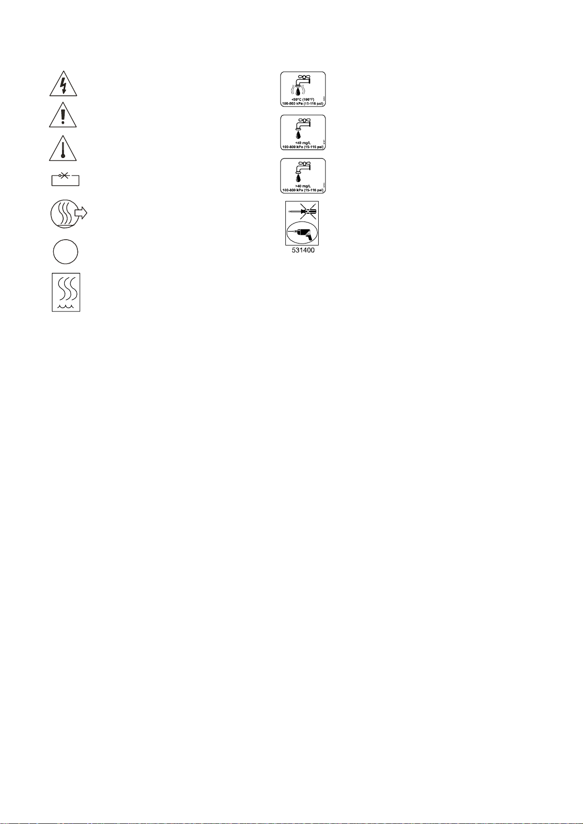
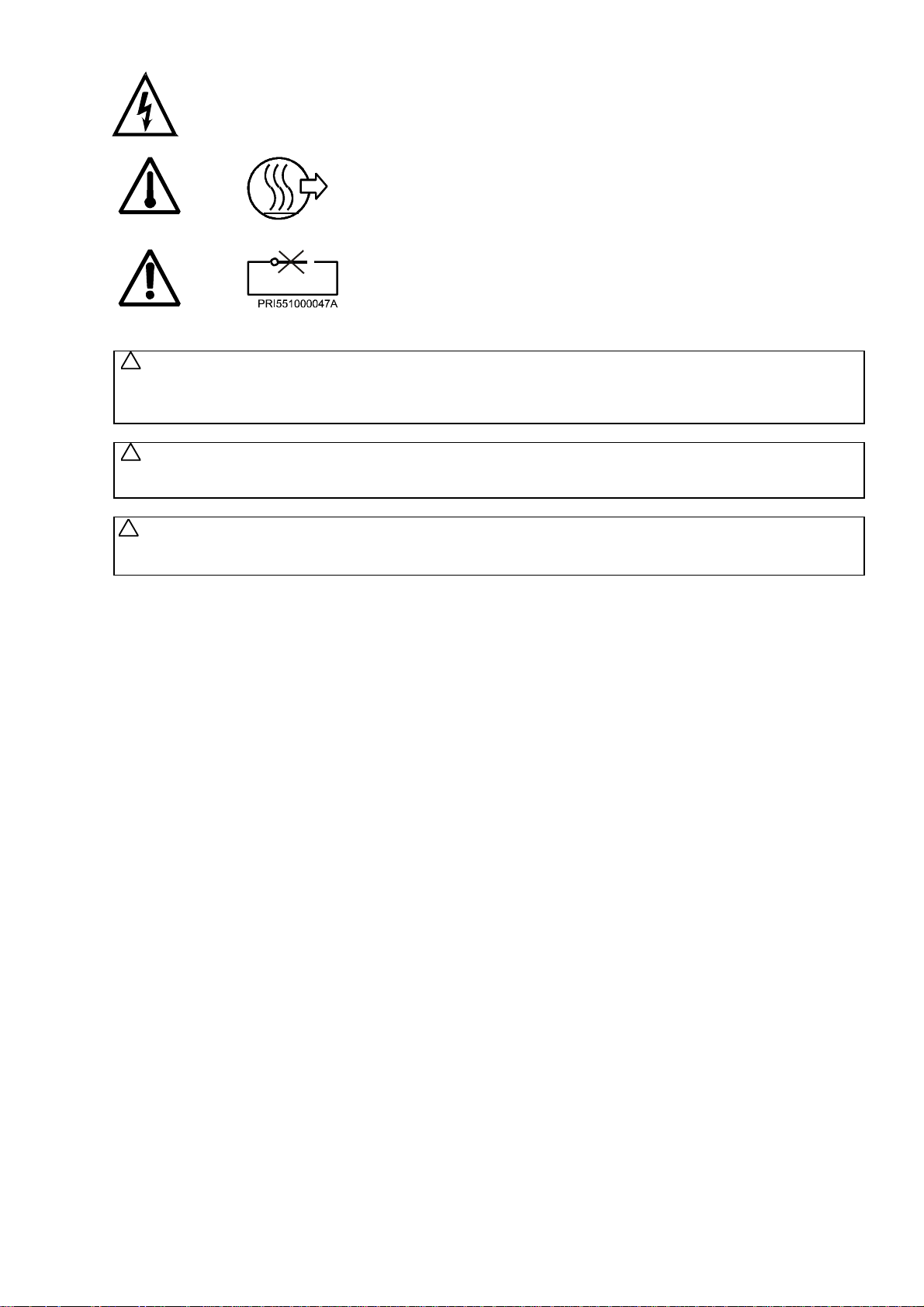
3. SYMBOLS ON THE MACHINE
Caution, dangerous electrical tension,
electric al dev ic es
Caution, other danger , read and follow
written i nstr uc tions
Caution - Increased temperature
Do not close or cover
Warm water inlet
(red color of the l abel)
Soft cold water inlet
(light blue color of t he label)
Hard cold water inlet
(dark blue of the label)
The machine hot air outlet
In case of emergency pr ess the emergency
button to stop t he machine
Steam
The holes to be drilled not punched
4 USER'S MANUAL 504615_I_PUB_DATE_28_AUG_2009.DOC
Page 7
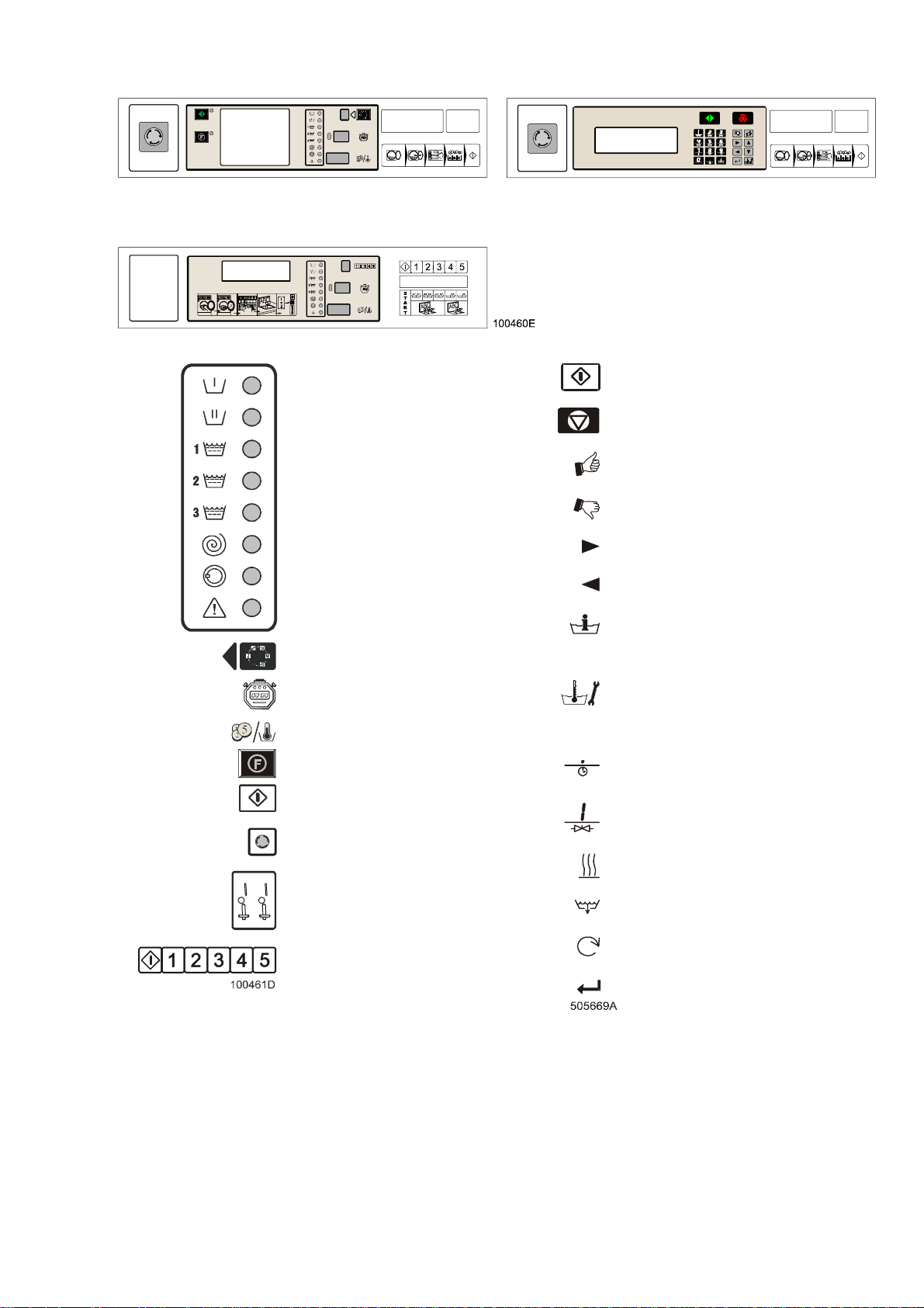
EASY CONTROL MICROPROCESSO R GRAPHITRONIC MICROPROCES SOR
EASY CONTROL MICROPROCESSO R
WITH MECHANICAL BUTTONS
PREWASH
START (advancing program)
MAIN WASH
RINSE 1
RINSE 2
RINSE 3
EXTRACT
DOOR RELEASE
FAULT
PROGRAM SELECT
CYCLE TIME
COIN/TEMPERATURE
FUNCTION BUTTON
START
EMERGENCY STOP KNOB
(O nly us ed by not coin w asher extr acto r s)
COIN SYSTEM
STOP (interupting program)
YES SELECTION
NO SELECTION
INCREASING SEQUENCE TIME
DECREASING SEQUENCE TIME
INFO ( overview available wash programs and
wash sequence functions)
SERVICE (s hows a ctual water temperature
and level, number of fullfilled cycles and
actual state)
ACTIVATES THE TIME DELAY FUNCTION
(delay time will be started by pressing start)
OPENING THE INLET VALVES
ACTIVATE HEATING
OPEN DRAIN VALVE
SPEED ADJUST
PROGRAM SELECT
ENTER – SELECTION OR CONFIRMATION
504615_I_PUB_DATE_28_AUG_2009.DOC USER'S MANUAL 5
Page 8
4. OPERATION INSTRUCTIONS
4.1. BEFORE WASHING
Sort the linen acc or ding on the temperature and the instruc tions of the manufacturer of t he fabrics. Check
if there aren‘t any strange objects between the linen li ke nai ls, screws, needles, etc. in order not t o dam age
the washer-ext r ac tor or the linen. Turn sleeves of shirts, blouses, etc. inside out. To get a better washing
result, you hav e to unf old the fabrics and mix the bigger and smaller pieces of fabrics.
4.2. OPEN THE DOOR
Open the door by pulling on the door handle.
4.3. LOADING THE WASHER
!
CAUTION!
The optimal washing load is determined by the filling f actor . The proper filling fact or is determined by the type
of linen and other factors. Cotton textiles normally require a filling factor of 1:10-1:13, which is a full drum load.
Put the linen in the dru m de pend ing on the maximu m capacity of the w as her. Do not overload the was her e xtracto r.
Overloading the machine can lead to a bad wash result. Half washing l oads can obstruc t a proper function.
Synthetics and blended fabrics usually require a filling factor of 1:18-1:20, which is half drum load. Loading more
will reduce the wash result and can damage the linen.
4.4. CLOSE THE DOOR
Close the door with t he door handle, making sure the door is properly latched before operating the washer.
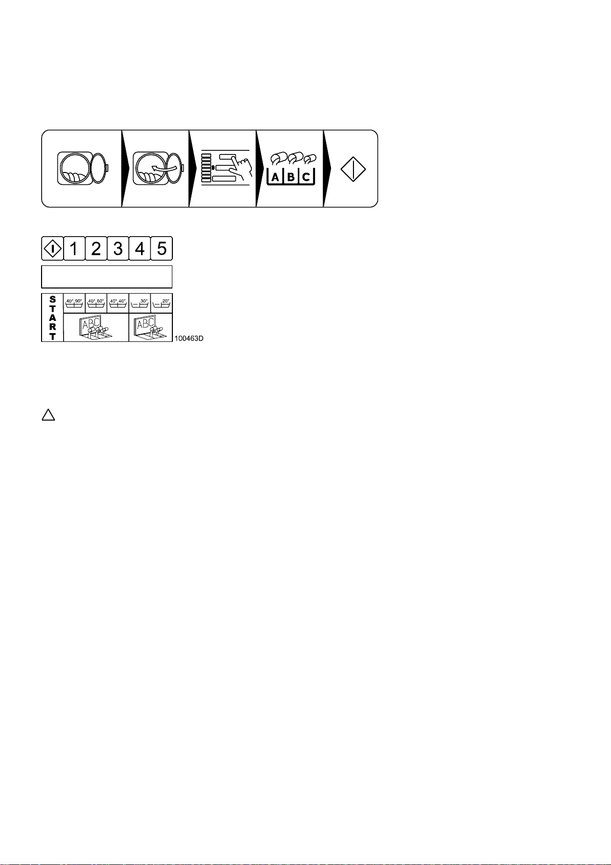
4.5. PROGRAM SELECTIONS
Choose one of the available wash programs, best correspondi ng to the quality of the garments and all owed
wash temperature in the wash load. Insert the wash program number. The different washing programs are indicated
on the operator panel. The selection of the program determines the temperature and the time for washing
and rinsing, the wash action and the spin speed and time.
Note: For locking a program mode, changing factory settings and possibiliti es of pr ogr am c hanges
and setup - see Programming m anual.
6 USER'S MANUAL 504615_I_PUB_DATE_28_AUG_2009.DOC
Page 9
4.6. WASH PROGRAMS OVERVIEW
Wash program 1: Hot wash 90°C
Wash program 2: Warm wash 60°C
Wash program 3: Coloured wash 40°C
Wash program 4: Bright col our ed wash 30°C
Wash program 5: Woollens 15°C
Wash program 6: Hot wash 90°C ECONOMY level
Wash program 7: Warm wash 60°C ECONOMY level
Wash program 8: Coloured wash 40°C ECONOMY level
Wash program 9: Bright col our ed wash 30°C ECONOMY level
EASY CONTROL: Wash program A:
GRAPHITRONIC: Wash program 10:
EASY CONTROL: Wash program B:
GRAPHITRONIC: Wash program 11:
EASY CONTROL: Wash program C:
GRAPHITRONIC: Wash program 12:
EASY CONTROL: Wash program D:
GRAPHITRONIC: Wash program 13:
EASY CONTROL: Wash program E:
GRAPHITRONIC: Wash program 14:
EASY CONTROL: Wash program F:
GRAPHITRONIC: Wash program 15:
Hot wash 90°C SUPER ECONOMY level
Warm wash 60°C SUPER ECONOMY level
Coloured wash 40°C SUPER ECONOMY level
Bright col our ed wash 30°C SUPER ECONOMY level
Extraction low speed
Extraction high speed
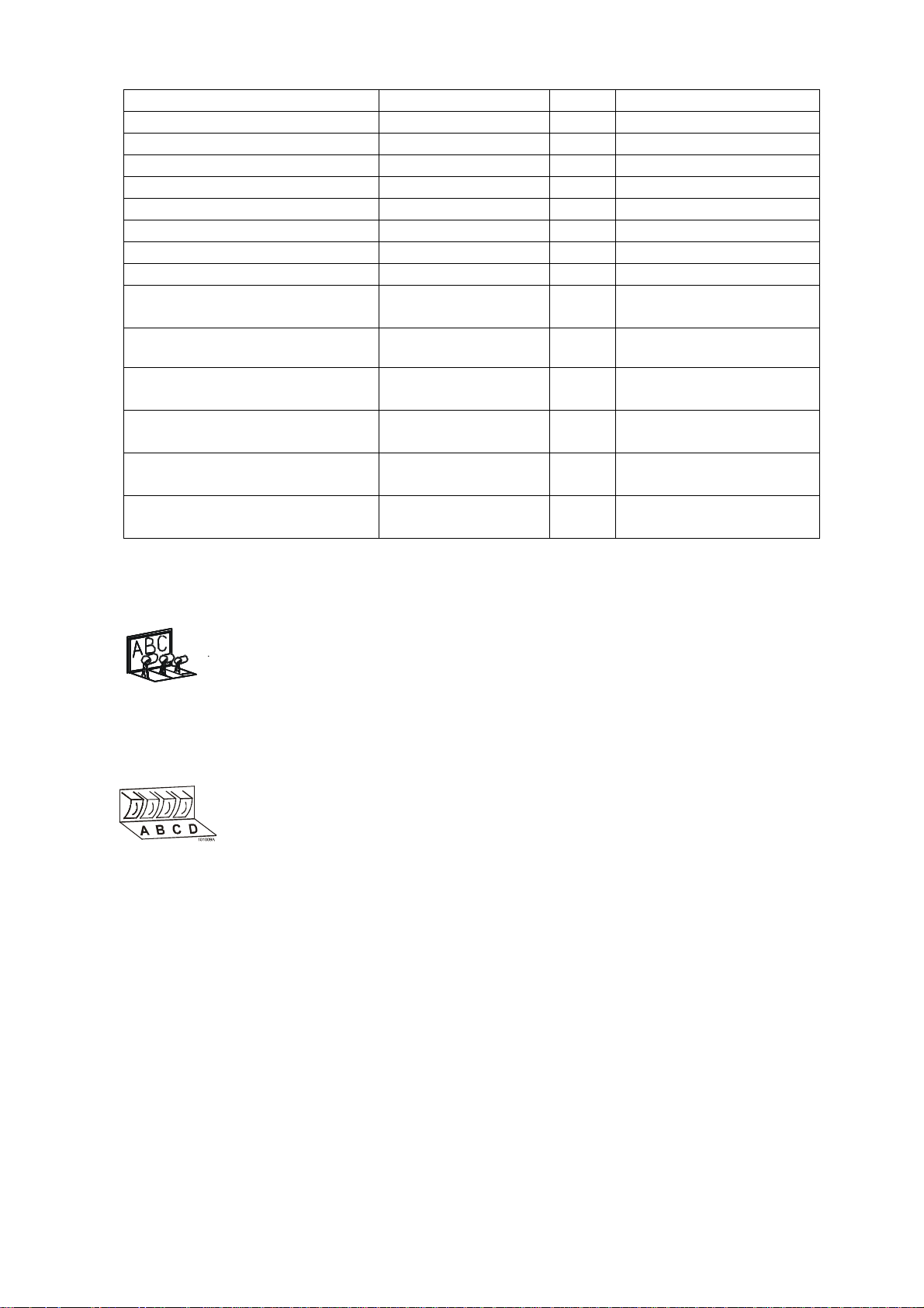
4.7. ADD DETERGENTS
Fill the soap dispenser on the top of the washer extractor dependi ng of the chosen program.
Dispenser A: Prewash (add the detergent at t he beginning of the wash cycle)
Dispenser B: Wash (add powder detergent or bleach detergent at the beginning
of the cycle, you may add liquid detergent or liquid bl each during the wash cycle.
If added at the start of the cycle, it will run in the washer prematurely)
101008
Fill the soap dispenser at the front or side of the washer extr actor depending of the chosen program.
Add the detergents before the start of the wash cycle.
R Standard wash programs versu s custom made wash programs.
This explanation is only valid f or standard wash prog rams. For custom made programs, it’s possible that
other dispensers have been selected. (See programming manual)
R Remark
- It is advisable to use onl y deter gents with „foam breaker“ which c an easi ly be found in retail shops.
The dosage of soap to use is generall y menti oned on the packing. An overdose of detergent can lead
to poor wash results and „suds“ ov erflow which can damage the machi ne.
- Take care that the lid of the soap di spenser is closed if the machine star ts.
Dispenser C: Final Rinse (Add f abr ic softener at the beginning of the cycle or before
the final rinse)
Dispenser A: 1 st Wash
Dispenser B: 2 nd Wash
Dispenser D: Last Rinse
:
504615_I_PUB_DATE_28_AUG_2009.DOC USER'S MANUAL 7
Page 10
4.8. START THE WASHER
4.8.1. EA SY CO NTRO L MIC ROPRO CESSOR WI TH KEYPAD AND MECHA NICA L BU TTONS
COIN OPERATED MODELS
A. After choosing the pr ogr am with the PROGRAM SELECT button,
throw the right am ount of coins in the slot indicated on the lower
display The displ ay shows the remaining amount that has to be
thrown in. If the di spl ay shows 00, the washer extractor can be
started. The little light by the start button will be flashing.
B. Push the START butt on to start t he washer ex tractor. When you
have select ed a wrong washing progr am, you can change it
during the fi r st 150 seconds of the program by pushing the
SELECT button. When a mor e expensive washing program was
chosen, the value will be shown to add. When you don‘t add more
coins, the chosen program at the start will be executed.
C. During the washing cycle you can follow the actual washing
sequence and the remaining time on the displays.
NON-COIN OPERATED MODELS
A. After choosing the pr ogr am with the PROGRAM SELECT button,
push the START button to start the washer extractor.When you
have select ed a wrong washing progr am, you can change it
during the fi r st washing step by pushing the SELECT button.
B. During the washing cycle you follow the actual washing sequence,
the remaining t ime and if been set the temperature on the displays.
C. If the advance function has been set by the installator, you c an go
on to the next step by pushing t he STA RT but ton.
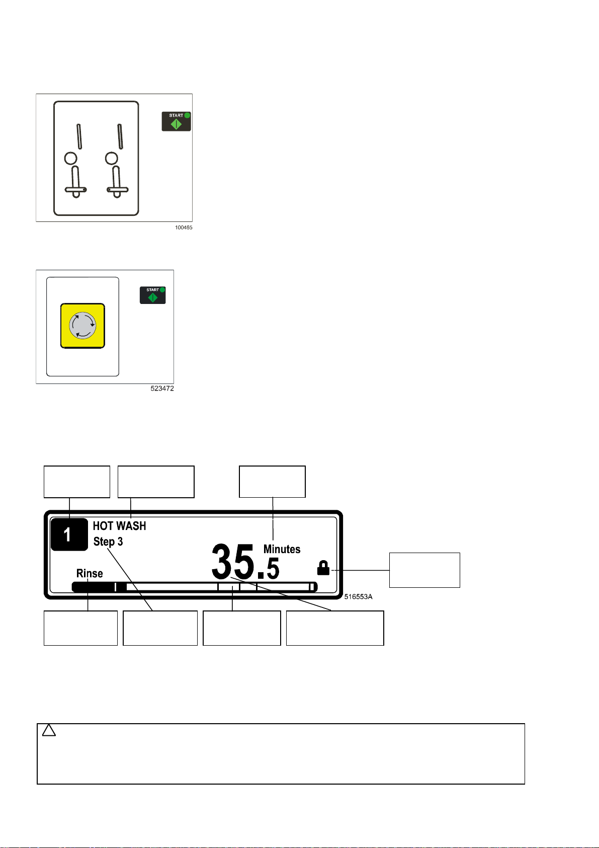
4.8.2. GRAPHITRONIC MICROPROCESSOR
After selecting the desired wash program number, by press ing the START button the wash cycle w ill be started.
If there is no washing program available for the selected pr ogr am num ber, „INVALID will be displayed“.
Program
Number
Wash/Spin
Sequence
Wa sh Cycle
Name
Wa sh Cycle
Step
Progression
Bar
Units
Door State
Remaining Time
Wa sh Cycle
4.9. END OF WASH CYCLE
4.9.1. EASY CON TROL MI CROP ROCESS OR WI TH KEYPA D A ND M ECHANI CA L BUTTON S
You can see clear ly the end of the wash ing cyc le on th e oper ator panel when the ligh t next to the door symbol
lights up and the tim e displ ay indicates „0“. Open the door with the door handle and take out the fabrics
of the washer extrac tor.
WARNING!
!
IF YOU CAN’T OPEN THE DOOR, FOR EXAMPLE BY A POWER FAILURE, WAIT A CERTAIN TIME
UNTIL THE SECURITY SWITCH IS COOLED DOWN. THIS IS A SAFETY! THE DOOR CAN BE OPENED
AFTER A COUPLE OF MINUTES. MAKE SURE THAT THE DRUM HAS COMPLETELY STOPPED
AND DRAINED BEFORE OPENING THE DOOR.
8 USER'S MANUAL 504615_I_PUB_DATE_28_AUG_2009.DOC
Page 11

When a power failure occ ur s for a short time, the wash program will conti nue when the power comes back
on. When the fail ur e occurs for a longer time and the door is still closed the display and the light next to the
start button starts flashing when power is restored. If the door is still locked the timer will continue the program.
For machines initi alised as coin operated models, the door will be locked immediately . Press the start button
to continue the pr ogr am . If the door was opened, the program will be resetted.
4.9.2. GRAPHITRONIC MICROPROCESSOR
WARNING!
!
IF YOU CAN’T OPEN THE DOOR, FOR EXAMPLE BY A POWER FAILURE, WAIT A CERTAIN TIME
UNTIL THE SECURITY SWITCH IS COOLED DOWN. THIS IS A SAFETY! THE DOOR CAN BE OPENED
AFTER A COUPLE OF MINUTES. MAKE SURE THAT THE DRUM HAS COMPLETELY STOPPED AND
DRAINED BEFORE OPENING THE DOOR. AT THE END OF THE THE WASH CYCLE, WHEN THE
REMA IN IN G PR OGR AM TIME REACHES 0 , P R OGR A M E N D IS D IS PLAYED. WHEN U N LOA D A PP EA R S
ON THE DISPLAY, OPEN THE DOOR BY THE DOOR HANDLE AND TAKE OUT THE GARMENTS
OF THE WASHER EXTRACTOR. (ONLY FOR MACHINES WIT H „GRAPHITRONIC“)
4.10. HOW TO OPEN THE DOOR BY FAILURE
See Installation and maintenance manual.
504615_I_PUB_DATE_28_AUG_2009.DOC USER'S MANUAL 9
Page 12

5. FIRST SERVICE AT TECHNICAL PROBLEM
N° Failure message Failure Action Fault occurrence
E1
E2
E3
E4
E5
E6
E7
E8
E9
E10
E11
E12
E13
E14
E15
E21
E22
E24
E25
E26
E27
E28
No Drain Co
No Drain
Tilt Faul t
Imbalance
Tilt High Sp
Door Coil
Door Switch
Door Start
Door Unload
Bimetal/Spring
No Fill
Overfill
No Heating
Heat Time
Too Hot
Overflow
Flush fault
Level Sens
Temp Sensor
Mitsub code
Comm fault
THT time / E.OL
E29 OV3 time /
E.OP
E31
E32
E33
Load Parr
Verify Parr
Stall prev
E35 Wrong Softw
E37 No Drain Sp
E38 No Recycle
Drain failure
Cooldown
Drain failure Full Stop + tumble Draining sequence
Out of balance :
Before spin
Out of balance :
Normal spin
Out of balance : high
spin
Door switch failure Full stop + safety time Whole cycle
Door solenoid switch
failure
Door lock check at
start failure
Door lock switch
closed failure
Bimetal/Spring Continue 2 min 30 sec after start
Fill failure Full stop + reque st for
Overfill fa ilu re Full stop + tumble While filling
Heating failure Full stop + tumble While heating
Heating time failure Full stop + request for
Too Hot Full stop + tumble While heating
Overflo w fa ilure Full stop + tu mble Wash ste p
Flush failure Full stop + tumble Flush step
Defec tive level
sensor
Defec tive
temperature sensor
Undefined frequency
inverter error code
Communication fault
inve rter
THT T ime o u t / E.OL Full s to p + safety time At s p in s e q uence
OV3 Time o u t /
E.OP
Initializ a tio n fa u lt
inve rter
Verificatio n fa u lt
inve rter
Stall prevention
function active
Wrong software
version
Drain failure at the
Spray Sequence
The Tank with
recycle water is
empty
E39 Out of Soap The Soap Supplies
are running Out of
Soap
E40 No Fill Rec Fill failure d u e to an
empty water recycle
Tank
E41 Service Due Service Due
Warning
E42 Connection No Network
Connection
Full Stop + tumble Draining sequence
Cooldown
Full stop + tumble Start sp in
Skip + c o n t in ue After 1 0 x tilt
Full stop + safety time >500 or 750 RPM
Full stop + safety time Whole cycle
Don’t sta rt At start up
Don’t start End cycle
cycle
While filling
Continue
While heating
Continue
Contin ue + Don’t sta rt Before sta rt up
Contin ue + Don’t sta rt Before sta rt up
Full stop + tumble Whole cycle
Full stop + safety time Whole cycle
Full stop + s a fety time At spin s e q uence
Don’t st a rt At initialization
Don’t start At loading parameters
Continue At spin sequence
Don’t sta rt New s o ftwa re version
Full sto p + tu mble Spray Sequence
Warning at the End.
Front soap dispenser
Mach. only
For Info o n ly Wash s tep
Full stop + Request for
Continue
Top soap dispenser
Mach. only
For Info o n ly
Open d oo r = re set
For Info o n ly Data Tra nsfer Networking
Wash step
Wash step
End cycle
10 USER'S MANUAL 504615_I_PUB_DATE_28_AUG_2009.DOC
Page 13

E43 Voltage Par Wrong Voltage
Range Selection
E44 Model type Wrong Inve rte r
Model Type
E45 No Speed
Sensor Signal
No Speed pulses
when drum tur ns.
Make correct selection Configuration menu
Make correct selection Configuration menu
Continue + Warning At spin sequence
(FS120 only)
E46 Brake Closed Brake Stays Closed Full stop + safety time At spin sequence
(FS120 only)
E47 Brake Wear Out Friction blocks
brake are wear-out
Full stop + s a fety time Any time
(FS120 only)
E48 Brake Open Brake Stays Open Continue + Warning At spin sequence
(FS120 only)
E49 UnBalance
Switch At Wash
E50 No Second
Acceleration
Ramp
E51 No Third
Acceleration
Ramp
E52 Board Memory PCB-EEPRROM
E53 Board Data PCB-EE PR OM Data
E57 Lock System Door Lock Switch
E58
E59
E60
E61
E62
E63-
No Free Run
Run Free Run
No reset Drive
Continue spin
Extended speed
Motor Drive
E67
E68
E69
E70
E71
E72
E73
E74
E75
E78
E79
No Sign Spin
RS Unbalance
RS7 Select
RS10 Select
KEB ST LOW
KEB ST HIGH
CFIStuck
KEB code
Lock Active
Lock Start
Air suspension
without compressed
air
Missing wire bridge
inverter / wrong
inverter parameters
Missing wire bridge
inverter / wrong
inverter parameters
CRC failure
out of range failure
stays closed when
the outer door is
open.
Deceleration end of
spin w h ile brake is
closed.
Run Status inverter
=1 while brake is
closed.
No detection motor
speed signal at
wash
Motor doesn't stop
spinning anymore
Motor sp ins too fa st Full stop + sa fe ty ti me
Reset M oto r Drive fo r
E60, E61 & E62
No detection motor
speed signal at spin
Unbalance input
should not be high on
R machines
RS7 selected in case
of RS10
RS10 selected in
case of RS7
No wire bridge
terminals 16-20
No KEB parameters
loaded in inverter
Inverte r n o t sw itc hed
off at end of cycle.
Undefined frequency
inverter error code
At standby door lock
is locked nevertheless
door is open.
After pressing Start
door lock is locked
nevertheless door is
open.
Full stop + s a fety time Wash action
Continue At spin sequence
Continue At spin sequence
Don't start At Power Up
Don't Start At Power Up
Don’t Start At locking sequence
Full stop + s a fety time At spin s e q uence
Full stop + s a fety time At spin s e q uence
Full stop + s a fety time
Full stop + sa fe ty ti me
Reset Motor Drive Wash Se q uen ce
Full stop + tumble Spin Sequence
Don't Start
Full stop + tumble
Don't Start Start Cycle
Don't Start Start Cycle
Don't Start Start cycle
Full st op + sa fety time Start cycle
For Info only End of cycle
Full stop + tumble Whole cycle
Don't Start At Standby
Don't Start At Start Cycle
(FS120 only)
(FS120 only)
(FS120 only)
(MB70-90-110-140-180
only)
(FS120 only)
(FS120 only)
Wash Sequence
Whole cycle
Whole cycle
Sta r t Spin sequence
Whole cycle
504615_I_PUB_DATE_28_AUG_2009.DOC USER'S MANUAL 11
Page 14

E80
Time Out
Input16
E81
E82
E83
E84
E85
E86
E100
No Reheat Heating F a ilure Full stop + tumble.
No Refill
Cycle Fail No successful wash
No Store PC Communication
RTC Low Batt Real Time Clock, No
No RTC Comm Real Time C lock is
Weigh No
Comm
E101
E102
E103
E104
E105
E300
Weigh Low
Weigh High
Weigh Balance
Weigh Overload
Weigh Airbags No functional air
Mits Err Specific Mitsu b is h i
-
On Hold Signal
Failure S oap
Dispensing System
Refill failure Full stop + request for
cycle termination
failure with P C
Batte ry or b attery low
power
not available
Communication fault
weighing system
Weight machine is too
low
Weight mach ine is
too high
Weight is not
balanced over 4 load
cell's.
Weight on individual
load cell exceeds
max.
pressure system
Inverte r A la rm
Full stop + tumble. Whole cycle
Continue
Info that the wash cycle
has to be repeated .
For Info only. End cycle
For Info only. End cycle
For Info only. End cycle
Full Stop Tumble Before Start (MB16-MB180)
Don't Start Before S ta rt
Don't Start Before S ta rt
Don't Start Before Start
Full Stop Tumble Whole Cycle
Don't Start Before S ta rt
Full stop + safety time Whole cycle
Wash Step
(MB only)
Wash Step
(MB only)
Abnormal Cycle
Termination (MB only)
(MB only)
(MB only)
(MB only)
Whole Cycle (MB16-MB66)
(MB & FS23-55 only)
(MB & FS23-55 only)
(MB & FS23-55 only)
(MB & FS23-55 only)
(MB16-66 & FS23-55 only)
(MB70-180 only)
E353
E400
-
E441
E500
KEB Err Specific KEB
Inverte r A la rm
Full stop + safety time Whole cycle
Memory Err Memory E rro r Full stop + safety time Any time
-
E515
E550 DAQ Version
Err
E551 DAQ Write Err Problem writing
E552 DAQ Full Err DAQ Tra ceability
E553 Store DAQ>PC DAQ Traceab ility
E600
Softw Err Software Error Full stop + s a fety time Any time
Wrong DAQ
Memory ve rs ion
DAQ Me mory
Memory is F u ll
Memory is al most
Full
For Info o n ly Insta lla tio n n ew softw
For Info o n ly Tra ceability function, w h o le
cycle
For Info o n ly Tra ceability function, w h o le
cycle
For Info o n ly Tra ceability function, w h o le
cycle
-
E628
12 USER'S MANUAL 504615_I_PUB_DATE_28_AUG_2009.DOC
Page 15

INSTALLATION AND MAINTENANCE MANUAL
1. CONTENTS
1. CONTENTS.....................................................................................................................1
2. IMPORTANT SAFETY INSTRUCTIONS ........................................................................2
2.1. SYMBOLS ON THE MACHINE...........................................................................................................4
2.2. IMPORTANT INFORMATION BEFORE INSTALLATION....................................................................4
3. TECHNICAL SPECIFICATION .......................................................................................5
3.1. MACHINES 6 kg / 15 lb, 7 kg / 18 l b, 10 kg / 25lb, 13 kg / 30 lb CAPACITY..........................................5
3.2. MACHINES 18 kg / 40 lb, 22 kg / 50 lb, 27 kg / 60 lb, 35 kg / 80 lb.......................................................7
3.3. DIMENSI ONS AND COMPON E T S OF T H E MA C HINE...........................................................................9
4. INSTALLATION OF THE MACHINE.............................................................................11
4.1. HANDLING, TRANSPORT, STORAGE, UNPACKING.......................................................................11
4.2. F O UND A T I ON....................................................................................................................................11
4.3. PREPARING FOUNDATION BASE ......................................................................................................11
4.4. DIMENSIONS FOR FOUNDATION BASE.............................................................................................12
4.5. DIMENSIONS AND POSITIONING OF THE ANCHORING......................................................................13
4.6. D IMENSIONS A N D PO S I TIONIN G RIS E R S..........................................................................................14
4.7. HO W TO IN STA L L A WASHER........................................................................................................15
4.8. CONNECTIONS...............................................................................................................................15
4.9. PUTTING INTO SERVICE................................................................................................................22
5. MAINTENANCE............................................................................................................23
5.1. INTRODUCTION..............................................................................................................................23
5.2. DAILY...............................................................................................................................................23
5.3. EVER Y TH R E E M ONTHS ................................................................................................................23
5.4. EVERY SIX MONTHS ......................................................................................................................23
5.5. STEAM OR WATER FILTER............................................................................................................24
5.6. TIGHTENING OF BOLTS.................................................................................................................24
5.7. DOOR SEAL.....................................................................................................................................25
5.8. ADJUSTMENT GEAR BELTS...........................................................................................................25
5.9. REPLACEMENT WASHER FUSES..................................................................................................26
6. TROUBLE SHOOTING AIDS ........................................................................................27
6.1. EMERGENCY DOOR OPENING......................................................................................................27
6.2. ERROR INDICATION SHOWN ON DISPLAY...................................................................................27
7. LIST OF RECOMMENDED SPARE PARTS.................................................................28
8. PUTTING THE MACHINE OUT OF SERVICE..............................................................29
8.1. DISCONNECTING THE MACHINE...................................................................................................29
8.2. MACHINE DISPOSAL ......................................................................................................................29
504615 _I _P UB_DAT E_ 28 _A U G_2009.D O C INSTALLATIO N A N D MA IN T EN A NCE MANUAL 1
Page 16

2. IMPORTANT SAFETY INSTRUCTIONS
WARNING - SAVE T HESE INSTRUCTIONS FOR LATER USE.
Failure to compl y with the instructions may lead to incorrect use o f the appli ance, and may
result in r is k of fir e , bodily injuries or death and/or dam a ge to t he la undry and/or the appliance.
WARNING - Read the IMPORTANT SAFETY INSTRUCTIONS in this manual carefully before
operating th e appliance. Improper use of the appliance may cause risk of fire, electrical
♦ This English version is the original version of this manual. Without this version, the instructions are incomplete.
♦ Before installation, operation and maintenance of the machine read carefully the complete instructions, i.e.
this „Installation, maintenance and user's manual“, „Programming manual“ and „Spare parts manual“.
The Programming manual and Spare parts manual are not delivered with a machine by default. You shall ask the
supplier / manufacturer to obtain Programming manual and Spare parts manual.
♦ Follow the instruction written in manuals and keep the manuals in a proper place by the machine for later use.
♦ Safety instructions included in manuals for personnel operating the appliance must be printed and posted on a visible
place near the machine in the laundry room.
♦ The washer extractor is designed for fabrics washing only, other objects can damage the washer and can cause
damage or injuries.
♦ The manufacturer is not responsible for the damage to the fabrics that are washed by an inappropriate washing method.
♦ Always follow the instructions and/or warnings that are stated on the fabrics, washing products or cleaning products
mentioned by the manufacturer.
♦ The washer must be set up in accordance with the instructions. All drain, inlet, electrical connections, ventilation,
groundings and other connections must be done in according to the installation manual,
in compliance with the local standards done by qualified technicians with proper authorization.
♦ The valid standards for connecting to the local power network (TT,TN,IT,…) must be followed.
In the standard execution, the appliance may not be suitable for connecting to an IT supply syste m. Contact your
commercial distributor for assistance.
♦ All appliances are produced according the EMC-directive (Electro-Magnetic-Compatibility). They can be used
in restricted surroundings only (comply minimally with class A requir ements). For safety reasons there must
be kept the necessary precaution distances with sensitive electrical or electronic device(s).
♦ Do not change the parameters of the frequency inverter. This can cause serious injury, fire, washer damage, etc.
♦ During transportation and storage never use excessive forces on the packing because components can be
damaged protruding the contour line of the appliance.
♦ Use copper conductors on ly. Th is app liance must be connecte d to a supp ly circuit to which no ligh t ing un its
or general-purpose receptacles are connected.
♦ Any changes concerning the installa tion which are not des cribed in this Installa tion Ma nual must be appro ved
by the supplier or manufacturer. Otherwise, the supplier and manufacturer are not responsible for potential injuries to
operators or for any damages. Interventions in the appliance execution or functions are not allowed, and the
manufacturer refuses any responsibility in such cases.
♦ The washer extractor must be installed on level. If not, the washer may become unbalanced during extraction
and, although fitted with an unbalance safety, the washer may become seriously dam aged what may result
in bo d i ly in jur ie s .
♦ Never put the was her in operation when the transporting braces are not removed. The washer should always be tested
before use.
♦ It is possible that there are residues of products used during the production proces in the new washer. These residues
could cause stains on your laundry. Therefore, you must first run at least 1 hot wash with old rags before using for your
normal laundry.
♦ Keep the appliance top and surface and the area around clean and clear of co mbustible or flammable products.
♦ Do not store flammable materials around the appliances. Define the dangerous areas in the laundry room and obstruct
an admission to them during appliances operating.
♦ Do not wash articles that have been previously cleaned in, wash in soaked in, or spotted with gasoline,
dry-cleaning solvents, or other flammable or explosive substances as they give off vapors that could ignite or explode.
♦ Do not add gasoline, dry-cleaning solvents, or other flammable or explosive substances to the wash water. These
substances give off vapors that could ignite or explode.
♦ Under certain conditions, hydrogen gas may be created in the hot water system that has not been used for two or more
weeks. HYDROGEN GAS IS EXPLOSIVE. If the hot water system has not been used for such period open all hot water
taps and let the water run out for few minutes. This will release any accumulated gas. As this gas is flammable, do not
smoke or use open flames during this time.
♦ TEMPERATURE IN WASHING MACHINE TUB: The electronic controller uses the temperature sensor in the tub to control
the temperature of the washing bath. There are a lot of things that have influence on the temperature measurement.
Therefore the temperature control of the washing bath is not very precise.
♦ Always strictly comply with the instructions that are written on the laundry chemicals-, laundry aids-,dry-cleaning
solvents- and disinfectants packaging to avoid personal injury. Keep these agents out of the reach o f c hildren,
preferably in a locked cabinet.
shock or serious body injuries or death as well as serious damage to the appliance.
2 INSTALLA T I ON A ND MAI NTENANCE MANUA L 504615 _I _P UB_DAT E_ 28 _A U G_2009.D O C
Page 17

♦ Do not tamper the washer-extractor controls and do not bypass the safety instructions and the warnings.
♦ Do not use some means on the soap dispenser lid to hold it open by filling or when the machine operates. The discharge
or splashing of hazardous liquid can cause serious scalding and burning.
♦ Do not operate the appliance when parts are broken or missing or when covers are open. The appliance may not be
operated until the fixed guards are put correctly in place.
♦ The appliance must not be stored, installed or exposed to the weather, extreme low or high temperature and humidity
levels. Do no t hos e dow n the wa she r. NEVER a llow the app lian ce to g et we t.
♦ Check the functioning of the door lock mechanism on regular base. NEVER bypass the doorlock mechanism.
♦ Disconnect the power and clos e all water and steam supply before cleaning, se rvicing and at the end of each
operating day.
♦ Out of the venting at the back of the w asher can escape warm vapor or and hot air. Do not co ver the vent but protect it
sufficiently. It serves air gap and as a vapor outlet to prevent pressure building in the washer.
♦ Do not repair or replace any part of the appliance or attempt any servicing unless specifically recommended in
the service manual or published user-repair instructions that you understand and have the skills to c a r r y out.
Only qualified service personnel may open the appliance to carry out servicing.
♦ Information contained in this manual is intended for use by a qualified service technician familiar with proper
and safe procedures to be followed when repairing an electrical appliance. All tests and repairs should be performed by
a qualified service technician equipped with proper tools and measuring devices. All component replacements
should be made by a qualified service technician using only factory approved replacement parts.
♦ Improper assembly or ad jus tmen t may occur if service or repa ir is attemp t ed by persons other then qualified
service technicians or if parts other then app ro ved rep lace ment pa rts a re us ed. I mproper as s embly o r ad justment
can create hazardous conditions.
♦ There can be a risk of injury or electrical shock while perf or ming s ervi c es or repairs . Injur y or elec tric al shoc k
can be serious or even fatal. Consequently, extreme caution should be taken while performing voltage checks
on individual componen ts or a product. PLEASE N O TE: E xcept as ne ces sary to per form a particular in ser vicing
a product, the electrical power supply should ALWAYS be disconnected when servicing a product.
♦ All in dustr ial (OPL - On Premise Laund ry) washe rs are designed for use in Laun dry with p rofessiona lly trained attendan ts.
♦ Before the appliance is removed from service or discarded, remove the door.
♦ Any Water or Steam Leaks Must Be Repaired Immediately. Closed supply immediately.
♦ If any problems or failures should arise, immediately contact your dealer, serviceman or manufacturer.
♦ The manufacturer reserves the right to change the manuals without previous notice.
!
WARNING -- CAUTION
This appliance must be connected to a grounded metal, permanent wiring system, and additionally an
equipment-grounding conductor must be run with the circuit conductors and connected to the equipmentgrounding terminal or lead on the appliance.
!
WARNING -- CAUTION
In order to minimize the risk of fire, electrical shock and injury, THIS WASHER MUST BE PROPERLY GROUNDED
.
Never plug in or direct-wire an appliance unless it is properly grounded in accordance with all local and national
codes .
If more appliances in the same location, mutual grounding must be applied where possible.
!
WARNING -- CAUTION
The washer extractor is intended to be permanently connected, it MUST be secured mounted to a NON-COMBUSTIBLE,
adequate floor structure. A concrete foundation is required. Metal reinforced w o od f loors are NOT al l owed
due to the risk of fire and excessive vibrations.
NEVER install the washer on an upper floor or over a basement without a load sup port designed by a structural
engineer.
!
WARNING -- CAUTION
Looking at the machine f rom the f ron t view th e drum ro t at io n durin g ext ract ion must be clockwise.
WARNING - Although t he appliance may be in the „off“ position, there is still electric al power to the switch
!
supply terminals.
!
WARNING - When power supply has been switched off wait for at least 10 minutes before starting inspection
or servicing the was her . Be fore sta rting inspe c t ion o f fre quen cy in verter, che ck fo r residual voltage across ma in
circuit terminals + and -. This voltage must be below 30 VDC before you can access the inverter for inspection.
!
WARNING - Do not allow children to play on, in or around the applianc e at any tim e. Close supervision
of children is necess ary w hen the app liance is used near children. Never permit ch ildren to opera te the app liance .
!
WARNING - Do not open door until c yli nder r em ains stopped and wat er has been drained completely.
If the door safety loc k does not work, do not use washer until the door lock mechanism is repaired.
504615 _I _P UB_DAT E_ 28 _A U G_2009.D O C INSTALLATIO N A N D MA IN T EN A NCE MANUAL 3
Page 18

CAUTION! - Follow all valid basic safety rules and laws. The instructions in this manual cannot ac c ount
!
for every possibl e danger ous sit uation. They must be generally understood. Caution and c ar e ar e factors
which can not incl uded in the design of the appliance and all persons who install, operate or maintain
the applianc e must be qualif ied and familiar with the operati ng inst r uc tions. It is up to the user to take proper
care when operating the appliance.
!
CAUTION! - Do not remove warning signs placed on the applianc e. Observe signs and labels to avoid
personal inj uri es. S afety labels appear at crucial loc ations on the appliance. F ailure to maintain legible safety
labels coul d result in injury to the operator or service technician.
CAUTION! - If the installed appliance operat e with coi n, token or similar operation f or use in self-service
!
situati ons, then the owner-installer m ust pr ov ide a remote-located emergency stop devi c e. T his device must
be placed in such a way that it is easy and safely accessible for the users. The em er genc y stop dev ice
takes care that at least t he c ontrol circuit of the appliance i s inter rupted.
2.1. SYMBOLS ON THE MACHINE
See - User's manual.
2.2. IMPORTANT INFORMATION BEFORE INSTALLATION
FOR TRANSPORTATION AND STORAGE
IN CASE OF TRANSPORTATION AND STORAGE, WATCH COMPO NE NTS PROTRUDI NG
FROM THE CONTOUR LINE OF MACHINE (DOOR LOCKS ETC.), TO AVOID INJURIES .
– Never push, pull or exert pressure on components protruding fr om the m ac hine c ontour line (controls,
door locks etc.).
– Make sure that these components are secured so as to avoid damages during m ac hine manipulation
and installation.
– In case of the machine transportation by the customer, follow the manufacturer's instructions for transportation,
handling and storage of the product. In case of transportation of machine by the customer the manufacturer
is not responsible f or possible damage of machine in the course of transport ation. In case of storage
the machine in a free area it must be protected against mechanical damage and weather condition factors.
FOR INSTALLATION
ALL CONNECTION, AND IN SPECIAL PROTECT ING EARTH, MUST BE PERFORMED BY QUALIFIED
PERSONNEL WITH A PROPER AUTHORIZATION ACCORDING THE INSTALLATION MANUAL IN COMPLIANCE
WITH LOCAL STANDARDS.
– The washer must not be installed or stored in an area where it will be exposed to water and/ or weather.
Avoid damp conditions where water or moisture could run down the walls and covers of the washer or cover
the floor around t he washer. Do not install the washer above an open gut ter. Close any nearby gutters
so that waste water steam cannot collect near/insi de the washer.
– Any changes in the machine install ations must be approved by dealer or manufac turer. Otherwise the
dealer/manufacturer is not responsibl e for possible injuries or damages. Int erference and changes in the
machine construc tion are not allowed and the manufacturer r efuses any responsibilities in such cases.
– Define dangerous areas in the laundry room and do not allow people to enter if the machine is in operation.
MACH IN E INFORMAT IO N
– This manual comprises inf ormation for the whole series of rigi d - mount m ac hine series with a load of dry
linen 6, 7, 10, 13, 18, 22, 27 and 35 kg (15, 18, 25, 30, 40, 50, 60 and 80 lb) . V erify the machine model
according t o your order and the data plate located on back of washing mac hine, fig.3.3., pos.6 and find
corresponding information in the manual.
– The machines are controlled by e lectron ic pro gra mmer. F ind the programming instructions in the programming
manual.
– Additional heating can be provided by electrical heating elements or by steam from an external steam supply.
– Water inlets can use warm, cold soft and possibly also cold hard water.
– Electrical setup of the m ac hine is indicated on data plate, (see data plate, fig.3.3., pos.6) .
4 INSTALLA T I ON A ND MAI NTENANCE MANUA L 504615 _I _P UB_DAT E_ 28 _A U G_2009.D O C
Page 19

3. TECHNICAL SPECIFICATION
3.1. MAC HI NES 6 kg / 1 5 lb, 7 kg / 18 lb , 1 0 kg / 25 lb , 13 kg / 30 lb CA PAC ITY
DRY LOAD CAPACITY
(1/10)
PACKING DIMENSIONS
width
depth
height
transportation capacity
MACHINE DIMENSIONS
width
depth
height
INNER DRUM DIMENSIONS
diameter
depth
drum capacity
door opening
Netto
Brutto
Permitted dev iations
of feeding voltage
Permitted dev iations
of frequence
Electrical system
of the machine
Minimal power supply
voltage
NOMINAL OUTPUT
OF THE MOTOR A T RPM
INPUT PROTECTION
FOR ONE MACHINE
Electri c al heating
Without electrical heating
Overload pr otection
of the motor
maximum dim ensi ons i ncl uding protruding part s
*
*
6 kg / 15 lb 7 kg / 18 lb 10 kg / 25 lb 13 kg / 30 lb
DIMENSIONS
carton box
700 mm / 27.6“
730 mm / 28.7“
1180 mm / 46.5“
3
0.6m
/ 21.2 ft3
660 mm / 26“
710 mm / 28“
1045 mm / 41.1“
530 mm / 21“
270 mm / 10.6“
3
60 dm
/ 15.8 gal
290 mm / 11.4“
carton box
700 mm / 27.6“
730 mm / 28.7“
1180 mm / 46.5“
3
0.6m
/ 21.2 ft3
660 mm / 26“
710 mm / 28“
1045 mm / 41.1“
530 mm / 21“
330 mm / 13“
73 dm3 / 19.3 gal
290 mm / 11.4“
carton box
700 mm / 27.6 „
880 mm / 34.6“
1280 mm / 50.4“
3
0.79m
1140 mm / 44.9“
/ 27.9 ft3
660 mm / 26“
865 mm / 34“
530 mm / 21“
420 mm / 16.5“
95 dm3 / 25 gal
290 mm / 11.4“
carton box
810 mm / 31.9“
850 mm / 33.5“
1380 mm / 54.3“
3
0.95m
750 mm / 29.5“
820 mm / 32.3“
1225 mm / 48.2“
650 mm / 25.6“
395 mm / 15.6“
131 dm3 / 34.6 gal
410 mm / 16.1“
WEIGHT
140 kg / 309 lb
145 kg / 320 lb
140 kg / 309 lb
145 kg / 320 lb
185 kg / 408 lb
195 kg / 430 lb
195 kg / 430 lb
205 kg / 452 lb
ELETRICAL DATA
-6% to +10%V
±1% Hz
1x220-240V 50/60Hz - not applicable for electri c al heating
1x208-240V 50/60Hz - not applicable for electri c al heating
1x220V 50/60Hz - not appli c able for electrical heating
3x220-240V 50/60Hz
3x208-240V 50/60Hz
3x200V 50/60Hz
3x380-415V+ N 50/60Hz
3x380-480V 50/60Hz
342V / 180V 342V / 180V 345V / 180V 342V / 190V
0.6 kW
6kW / 3x220-240V /
20A
6kW / 3x400V / 16A
9kW / 3x220-240V /
32A
9kW / 3x400V / 20A
9kW / 3x440V / 16A
1x220-240V / 10A
3x220-240V / 10A
3x400V / 10A
3x440V / 10A
6kW / 3x220-240V /
6kW / 3x400V /
9kW / 3x220-240V /
9kW / 3x400V /
9kW / 3x440V /
1x220-240V / 10A
3x220-240V / 10A
electronic protection by the frequency inverter
Tab.3.1.
0.6 kW
20A
16A
32A
20A
16A
3x400V / 10A
3x440V / 10A
0.6 kW
6kW / 3x220-240V /
20A
6kW / 3x400V/16A
9kW / 3x220-240V /
32A
9kW / 3x400V/20A
9kW / 3x440V/16A
12kW / 3x220-240V /
40A
12kW / 3x400V /
25A
12kW / 3x440V /
25A
1x220-240V / 10A
3x220-240V / 10A
3x400V / 10A
3x440V / 10A
0,75 kW
6kW/3x220-240V/
20A
6kW/3x400V/16A
9kW/3x220-240V/
32A
9kW/3x400V/20A
9kW/3x440V/20A
12kW/3x220-240V/
40A
12kW/3x400V/25A
12kW/3x440V/25A
1x220-240V / 10A
3x220-240V / 10A
3x400V / 10A
3x440V / 10A
/ 33.6 ft3
504615 _I _P UB_DAT E_ 28 _A U G_2009.D O C INSTALLATIO N A N D MA IN T EN A NCE MANUAL 5
Page 20

DRY LOAD CAPACITY
(1/10)
6 kg / 15 lb 7 kg / 18 lb 10 kg / 25 lb 13 kg / 30 lb
WASHING FUNCTION
RPM OF THE DRUM:
washing
extracting
G - factor of spinning
48 rpm
580 rpm
100
CONNECTIONS
WATER CONNECTION
Water pressure
0.1 - 0.8 MPa / 1 - 8 bar / 14.5 -116 PSI
Recommended water
pressure
Water inlet
0.3 - 0.5 MPa / 3 - 5 bar / 43 - 73 PSI
BSP 3/4“
Maximal water
temperature
90°C / 194°F
DRAIN CONNECTION
Dimension
Capacity
Ø 76 mm / 3“
3.5 l / s
MACHINE VENTING
Venting connection
Ø 75 mm / 3“
of outer drum
STEAM C ONNECTION
Steam connection
Steam pressure low
Steam pressure high
Connections to external
liquid soap supply
1 - 3 bar / 14.5 - 44 PSI
3 - 8 bar / 44 - 116 PSI
standard 6 pcs,
(see electrical scheme)
G1/2“
Soap hoppers 3
CONSUMPTION
STEAM
Average steam
consumption (depends
on selected programme)
Maximum steam
consumption
6 kg. cycle
13.2 lb. cycle
0.01 kg.s
0.02 lb.sec
-1
/
-1
-1
/ 36 kg.h-1
-1
/ 79 lb.h-1
15.4 lb. cycle
0.01 kg.s
0.02 lb.sec
7 kg. cycle
-1
/ 36 kg .h-1
-1
/ 79 lb.h-1
-1
/
-1
WORKING CONDITIONS
Ambient temper ature
Relative humidity
Height abov e sea level
Storage temper ature
+ 5°C (41°F) to + 35°C (95°F)
30% to 90% without condensation
up 1000 m / 3280 ft
0°C (32°F) to +55°C (131°F)
ANCHORING
Bolt
FLOOR DATA
Max. static floor load
Max. dynamic floor load
Frequency of dy nami c
load
1.7 kN / 370 lb
3.6 kN / 801 lb
9.67 Hz
1.7 kN / 370 lb
3.6 kN / 801 lb
6 pcs M16 x 160
9.67 Hz
NOISE
Sound level
Leq (dB(A))
Tab.3.1. conti nuation
< 70 dB(A)
10 kg. cycle
22 lb. cycle
0.011 kg.s
-1
0.024 lb .sec
2.1 kN / 474 lb
4.5 kN / 1020 lb
9.67 Hz
-1
/
-1
/ 40 kg .h-1
-1
/ 88 lb.h-1
45 rpm
525 rpm
13 kg. cycle
-1
28.7 lb. cycle
-1
0.016kg.s
0.031lb.sec
/ 57.6kg.h-1
-1
/ 111 .6lb.h
2.6 kN / 577 lb
6.5 kN / 1450 lb
8.75 Hz
/
-1
-1
6 INSTALLA T I ON A ND MAI NTENANCE MANUA L 504615 _I _P UB_DAT E_ 28 _A U G_2009.D O C
Page 21

3.2. MACHINES 18 kg / 40 lb, 22 kg / 50 lb, 27 kg / 60 lb, 35 kg / 80 lb CAPACITY
DRY LOAD CAPACITY
(1/10)
18 kg / 40 lb 22 kg / 50 lb 27 kg / 60 lb 35 kg / 80 lb
DIMENSIONS
PACKING DIMENSIONS
width
depth
height
transportation capacity
MACHINE DIMENSIONS
width
depth
height
INNER DRUM DIMENSIONS
diameter
depth
drum capacity
door opening
Netto
Brutto
*
carton box
935 mm / 36.8“
955 mm / 37.6“
1530 mm / 60.2“
1.37 m3 / 48.4 ft3
855 mm / 33.7“
900 mm / 35.43“
1315 mm / 51.8“
700 mm / 27.6“
470 mm / 18.5“
3
181 dm
410 mm / 16.1“
280 kg / 617 lb
290 kg / 639 lb
/ 47.8 gal
ELETRICAL DATA
Permitted dev iations
of feeding voltage
Permitted dev iations
of frequence
Electrical system
of the machine
Minimal power supply
voltage
NOMINAL OUTPUT
OF THE M OTOR A T RPM
INPUT PROTECTION
FOR ONE MACHINE
Electri c al heating
Without electrical heating
Overload pr otection
of the motor
maximum dim ensi ons i ncl uding protruding part s
342V / 190V 342V / 190V 342V / 190V 342V / 190V
1.5 kW
1x220-240V 50/60Hz - not applicable for electri c al heating
12kW / 3x220-240V / 50A
12kW / 3x 400V+N / 32A
12kW / 3x400V / 25A
12kW / 3x440V / 25A
18kW / 3x220-240V / 63A
18kW / 3x 400V+N / 40A
18kW / 3x400V / 32A
18kW / 3x440V / 32A
1/3x220-240V / 16A
3x400V+N / 16A
3x400V / 10A
3x440V / 10A
electronic protection by the frequency inverter
*
carton box
935 mm / 36.8“
1050 mm / 41.3“
1530 mm / 60.2“
1.5 m3 / 53 ft3
855 mm / 33.7“
1000 mm / 39.37“
1315 mm / 51.8“
700 mm / 27.6“
565 mm / 22.4“
217 dm3 / 57.3 gal
410 mm / 16.1“
WEIGHT
280 kg / 617 lb
300 kg / 661 lb
-6% to +10%V
±1% Hz
3x220-240V 50/60Hz
3x380-415V+ N 50/60Hz
3x380-480V 50/60Hz
1.5 kW
Tab.3.2.
wooden crate
950 mm / 37.4“
1220 mm / 48“
1570 mm / 61.8“
1.82 m3 / 64.3 ft3
870 mm / 34.3“
1140 mm / 44.9“
1380 mm / 54.3“
750 mm / 29.5“
610 mm / 24“
269 dm3 / 71 gal
504 mm / 19.8“
410 kg / 904 lb
470 kg / 1036 lb
2.2 kW
18kW / 3x220-240V / 63A
18kW / 3x 400V+N / 40A
18kW / 3x400V / 40A
18kW / 3x440V / 32A
24kW / 3x220-240V / 80A
24kW / 3x 400V+N / 50A
24kW / 3x400V / 50A
24kW / 3x440V / 50A
1/3x220-240V / 20A
wooden crate
1150 mm / 45.3“
1200 mm / 47.2“
1630 mm / 64.2“
2.25 m3 / 79.4 ft3
1100 mm / 43.7“
1140 mm / 44.9“
1460 mm / 57.5“
914 mm / 36“
505 mm / 19.9“
355 dm3 / 93.7 gal
504 mm / 19.8“
710 kg / 1565 lb
740 kg / 1631 lb
3 kW
3x400V+N / 20A
3x400V / 16A
3x440V / 16A
504615 _I _P UB_DAT E_ 28 _A U G_2009.D O C INSTALLATIO N A N D MA IN T EN A NCE MANUAL 7
Page 22

DRY LOAD CAPACITY
(1/10)
18 kg / 40 lb 22 kg / 50 lb 27 kg / 60 lb 35 kg / 80 lb
WASHING FUNCTION
RPM OF THE DRUM:
washing
extracting
G - factor of spinning 100 90 100 133
44 rpm
505 rpm
44 rpm
480 rpm
42 rpm
490 rpm
38 rpm
510 rpm
CONNECTIONS
WATER CONNECTION
Water pressure
0.1 - 0.8 MPa / 1 - 8 bar / 14.5 -116 PSI
Recommended water
pressure
0.3 - 0.5 MPa / 3 - 5 bar / 43 - 73 PSI
Water inlet
Maximal water
temperature
DRAIN CONNECTION
Dimension
Capacity
Ø 76 mm / 3“
3.5 l / s
MACHINE VENTING
Venting connection
of outer drum
STEAM CONNECTION
Steam connection
Steam pressure low
Steam pressure high
Connections to external
liquid soap supply
1 - 3 bar / 14.5 - 44 PSI
3 - 8 bar / 44 - 116 PSI
G1/2“
standard 6 pcs,
(see electrical scheme)
Soap hoppers 3
BSP 3/4“
90°C / 194°F
2 x Ø 76 mm / 2x3“
2 x 3.5 l / s
Ø 75 mm / 3“
G3/4“
1 - 3 bar / 14.5 - 44 PSI
3 - 8 bar / 44 - 116 PSI
CONSUMPTION
STEAM
Average steam
consumption (depends
on selected programme)
Maximum steam
consumption
18 kg. cycle
40 lb. cycle
0.021 kg.s
0.038 lb.sec
-1
/
-1
-1
/ 76 kg.h-1
-1
/ 137 lb.h-1
22 kg. cycle
49 lb. cycle
0.025 kg.s
0.055 lb.sec
-1
-1
/ 90 k g.h
-1
/ 199 lb.h-1
/
-1
27 kg. cycle
60 lb. cycle
-1
/
-1
35 kg. cycle
-1
0.032 kg.s
0.071 lb.sec
-1
/ 115 kg.h-1
-1
/ 256 lb.h-1
0.039 kg .s
0.086 lb.sec
77 lb. cycle
-1
/ 140 kg.h-1
-1
WORKING CONDITIONS
Ambient temper ature
Relative humidity
Height above sea level
Storage temper ature
+ 5°C (41°F) to + 35°C (95°F)
30% to 90% without condensation
up 1000 m / 3280 ft
0°C (32°F) to +55°C (131°F)
ANCHORING
Bolt
FLOOR DATA
Max. static floor load
Max. dynamic floor load
Frequency of dy nami c
load
3.1 kN / 675 lb
8.9 kN / 1994 lb
8.42 Hz
6 pcs M16 x 160 6 pcs M20 x 320
3.2 kN / 698 lb
9.6 kN / 2165 lb
8 Hz
4.5 kN / 985 lb
13.3 kN / 2996 lb
8.17 Hz
7.2 kN / 1598 lb
21.6 kN / 4863 lb
8.5 Hz
NOISE
Sound level
Leq (dB(A))
Tab.3.2. conti nuation
< 70 dB(A)
-1
/
-1
/ 309 lb.h-1
8 INSTALLA T I ON A ND MAI NTENANCE MANUA L 504615 _I _P UB_DAT E_ 28 _A U G_2009.D O C
Page 23

3.3. DIMENSIONS AND COMPONETS OF THE MACHINE
18/22/27 kg - 40/ 50/60 lb
only for
27 kg / 60 lb
6/7/10/13 kg - 15/18/25/30 lb 35 kg / 80 lb
Fig.3.3.
504615 _I _P UB_DAT E_ 28 _A U G_2009.D O C INSTALLATIO N A N D MA IN T EN A NCE MANUAL 9
Page 24

1. Control panel
2. Door handle
3. Service panel
4. Tub ventilation
5. Liquid soap hose connecti ons
6. Name plate
7. Steam connection
8. Drain connection
9. Earthing connection
10. Hot water connecti on
Machine
capacity
A
B
C
D
E
F
G
H
J
K
L
M
N
O
P
Q
R
S
T
U
V
W
Y
Z
6 kg
15 lb
660 mm
26“
1045 mm
41.1“
420 mm
16.5“
710 mm
28“
620 mm
24.4“
100 mm
3,9“
86 mm
3.4“
90 mm
3.5“
190 mm
7.5“
75 mm
3“
- - - - - - -
270 mm
10.6“
60 mm
2.4“
- - - - - - -
970 mm
38.2“
133 mm
5.2“
875 mm
34.4“
55 mm
2.2“
395 mm
15.6“
92 mm
3.6“
330 mm
13“
- - - - - - -
415 mm
16.3“
350 mm
13,8“
7 kg
18 lb
660 mm
26“
1045 mm
41.1“
420 mm
16.5“
710 mm
28“
620 mm
24.4“
100 mm
3,9“
86 mm
3.4“
90 mm
3.5“
190 mm
7.5“
75 mm
3“
270 mm
10.6
60 mm
2.4“
970 mm
38.2“
133 mm
5.2“
875mm
34.4
55 mm
2.2“
395 mm
15.6“
92 mm
3.6“
330 mm
13“
415 mm
16.3“
350 mm
13,8“
10 kg
25 lb
660 mm
26“
1140 mm
44.9“
460 mm
18.1“
865 mm
34“
780 mm
30.7“
100 mm
3,9“
86 mm
3.4“
90 mm
3.5“
190 mm
7.5“
75 mm
3“
270 mm
10.6
60 mm
2.4“
1062 mm
41.8“
133 mm
5.2“
962 mm
37.9“
55 mm
2.2“
395 mm
15.6
92 mm
3.6“
330 mm
13“
415 mm
16.3“
390 mm
15,4“
13 kg
30 lb
750 mm
29.5“
1225 mm
48.2“
420 mm
16.5“
820 mm
32.3“
740 mm
29.1“
100 mm
3,9“
86 mm
3.4“
90 mm
3.5“
190 mm
7.5“
75 mm
3“
270 mm
10.6
60 mm
2.4“
1145 mm
45.1“
182 mm
7.2“
1025 mm
40.4“
53 mm
2.1“
333 mm
13.1“
86 mm
3.4“
375 mm
14.8“
530 mm
20.8“
355 mm
13,98“
Tab.3.3.
11. Cold soft water connect ion
12. Cold hard water connection
13. Fuses
14. M a in switch
15. Switch: elect ri c al heating / steam heating
16. Electrical connection of machine
17. Plastic box for el ectri c al c onnec tion to liquid
soap pumps
18. Soap hoppers
18 kg
40 lb
855 mm
33.7“
1315 mm
51.8“
515 mm
20.3“
900 mm
35.43“
810 mm
31.9“
125 mm
4.9“
90 mm
3.5“
100 mm
3.9“
190 mm
7.5“
75 mm
3“
305 mm
12“
75 mm
3“
1215 mm
47,8"
205 mm
8.1“
1110 mm
43.7"
100 mm
3.9"
435 mm
17.1"
135 mm
5.3“
427,5 mm
16.8“
530 mm
20.8“
450 mm
17,7“
22 kg
50 lb
855 mm
33.7“
1315 mm
51.8“
515 mm
20.3“
1000 mm
39.37“
905 mm
35.6“
125 mm
4.9“
90 mm
3.5“
100 mm
3.9“
190 mm
7.5“
75 mm
3“
305 mm
12“
75 mm
3“
1215 mm
47,8"
205 mm
8.1“
1110 mm
43.7"
100 mm
3.9"
435 mm
17.1"
135 mm
5.3“
427,5 mm
16.8“
530 mm
20.8“
450 mm
17,7“
27 kg
60 lb
870 mm
34.3“
1380 mm
54.3“
455 mm
17,9“
1140 mm
44.9“
1043 mm
41.1“
160 mm
6.3“
85 mm
3.3“
90 mm
3.5“
190 mm
7.5“
70 mm
2.8“
260 mm
10.2“
170 mm
6.7“
1245 mm
49“
120 mm
4.7“
1135 mm
44.7"
135 mm
5.3"
470 mm
18.5"
90 mm
3.5“
435 mm
17.1“
630 mm
24.8“
380 mm
14,96“
35 kg
80 lb
1100 mm
43.3“
1460 mm
57.5“
510 mm
20.1“
1140 mm
44.9“
1041 mm
41“
125 mm
4.9“
85 mm
3.3“
100 mm
3.9“
195 mm
7.7“
124 mm
4.9“
360 mm
14.2“
305 mm
12“
355 mm
14“
84 mm
3.3“
1320 mm
51,9"
250 mm
9.8“
1220 mm
48.3"
100 mm
3.9"
972 mm
38.3"
90 mm
3.5“
400 mm
15.7"
300 mm
11.8“
630 mm
24.8“
430 mm
16,9“
10 INSTALLA T I ON A ND MAI NTENANCE MANUA L 504615 _I _P UB_DAT E_ 28 _A U G_2009.D O C
Page 25

4. INSTALLATION OF THE MACHINE
4.1. HANDLING, TRANSPORT, STORAGE, UNPACKING
For safety reasons, be sure that the persons that transport , handles and store the machines are i nformed
about the machines specif ications and information’s. Read and respect also the „IM PORTANT SAFETY
INSTRUCTIONS“.
The machines with capacity 6-22 kg / 15-50 lbs is delivered to the customer in a cardboard packing and crating
packing. Under the outside packing is the machine additionally protected by pol y ethylene foil.
Do not store or install the machine where it can be exposed to envi r onm ental conditions (rain, wind)
or extreme humidity.
The machines are fixed to the wooden palette by four bolt s M12x60.
Before moving the machine into its final location, follow the following precautions:
– Check all passages and spaces where the mac hine has to be tr ansport ed through, they must have
sufficient dim ensi ons to m eet the height and width of the machine including the package.
– Lift the machine up by lift truck or hand-operated pallet truck usi ng a transport skid to which the machine
has been attached.
Just before y ou install the machine in its final position, remove the packing, release four bolts of the pallet
and lift up the machi ne and r em ov e the wooden pallet.
It is possible to handle the machine by the fork lift or the manual truck if the forks supporting the sides of the frame.
If not, it can damage t he component s l oc ated in its lower part.
After unpacking , chec k if the machine has not been dam aged and if a ll the accessor ies are inc luded ac cor d ing
to your order. Verify the information of your machine at the name plate located on the machine rear and note
corresponding information in the information sheet at the back side of the manual.
The accessories and the m anual are placed inside the drum.
When moving the un-pac k ed m ac hine:
– Never p ush, pull or press the components pro t rud in g f rom the contour line of machine (front part ,
filling door, cont rol elements, belt cover, water inlet and outlet pipes etc.).
– Make sure that the filling door are secured t o av oid its opening during the handling.
4.2. FO UN DATIO N
GENERAL
For safety reasons, be sure that the persons that install ar e informed about the machines specifications
and informati on’s. Read and r espect also the „IMPORTANT SAFETY INSTRUCTIO NS “.
The washer is a rigid-m ount model, it MUST be securely fixed mounted to a foundation to work properly
and in a safe way.
Note: It is strongl y recomm ended that the 35 kg / 80 lb and 27 kg / 60 lb machines be mounted onto a not
elevated concrete base only. We also recommend it for the 18 kg / 40 lb, 22 kg / 50 lb.
CAUTION: - Putting machines on an elevation or riser creates a higher distance to reach the soap dispenser.
- Never put a riser on raised foundation.
- The washer needs to i nstalled always level or very sligh tly t ipped with front higher,
for sure not opposite. Therefore the foundation surface has to be made with these conditions.
NEVER install the washer on an upper floor or over a basement without a load support designed by a structural
engineer. It is required the installation be on a concr ete foundation. Metal-rei nforced wood floors and all not
concrete foundations are NOT allowed due to a potential for excessive vibrations and fire.
Improper installation will void the warranty. Manufacturer is not responsible for damage or injury
caused by improper installation.
4.3. PREPARING FOUNDATION BASE
Check the thickness of the existing floor and verify the quality of the concrete. The foundation MUST be always
been engineered to be able to co mp ly with the s tatic and dyna mic floor data. If necessar y con ta ct you r building
engineer.
Use 1360 kg / 3000 lb test concret e for the floor and foundation. For max. str ength, allow concrete to cur e
for min. of 72 hours in dry weather.
Layout and mark the area of the enti r e washer base tak e into account and respect the dist anc es to si des,
ceiling and r ear, see tab.4.4. Add also minimum 10 cm / 4“ on all sides of the entire washer base
for the foundat ion re-enforcement if it concerns a raised foundation, riser founda tion or a floor re-enfo rcement.
504615 _I _P UB_DAT E_ 28 _A U G_2009.D O C INSTALLATIO N A ND MAI NTENANCE MANUAL 11
Page 26

Break up the floor to a depth mention in the tab.4.4., accordance the machine model, inclu ding the min 10 cm / 4“
around all si des. If a higher capacity model stands on the right or left hands side, select the depth of the higher
capacity mode l for the co nce rne d mode l. Under cu t the s ides of the ho le to create an invert „mushroom“ effec t.
It is essential t o hav e a real good connection between the new foundati on and the existing floor, theref or e it
is necessary to place rebar that are well (chemical) anchored in the existing floor or other types of reinforcement
rods throughout the floor. Wet the hole well and brush the bottom and all sides with cement grout before pouring
in the new concrete. T his i s required for a solid foundation and joint.
If a raised foundation is used for some models, never make it higher then 30,5 cm / 12“. The overall dimensions
must also be equal with the total washer footprint plus the requi r ed 10 cm / 4“ on all sides.
4.4. D I MEN SION S F O R FO UN DA TI O N BASE
Fig.4.4.
12 INSTALLA T I ON A ND MAI NTENANCE MANUA L 504615 _I _P UB_DAT E_ 28 _A U G_2009.D O C
Page 27

Machine
capacity
A
B
C
D
E
F
G
H
I min.
J min.
K
L
M
N
O
P
Q min.
R max.
S min.
7 kg
18 lbs
530 mm
20.9 “
65 mm
2.6 “
100 mm
4 “
20 mm
0.79 “
48 mm
1.9 “
275 mm
10.83 “
90 mm
3.5 “
169 mm
6.7 “
600 mm
23.6 “
700 mm
27.6“
560 mm
22.1“
38 mm
1.5“
605 mm
23.82 “
300 mm
11.8“
120 mm
4.7“
40 mm
1.5“
7 mm
0.276“
300 mm
11.81“
M16
5/8“
10 kg
25 lbs
530 mm
20.9 “
65 mm
2.6 “
100 mm
4 “
20 mm
0.79 “
48 mm
1.9 “
365 mm
14.37 “
295 mm
11.6 “
34 mm
1.3 “
600 mm
23.6 “
700 mm
27.6 “
725 mm
28.54 “
38 mm
1.5“
605 mm
23.82 “
300 mm
11.8“
120 mm
4.7“
40 mm
1.5“
7 mm
0.276“
300 mm
11.81“
M16
5/8“
13 kg
30 lbs
594 mm
23.39“
78 mm
3.07“
100 mm
4 “
20 mm
0.79 “
43 mm
1.7 “
400 mm
15.75“
232 mm
9.13“
40 mm
1.6“
600 mm
23.6 “
700 mm
27.6 “
690 mm
27.2“
25 mm
1.0“
744 mm
29.3“
400 mm
15.7“
120 mm
4.7“
40 mm
1.5“
7 mm
0.276“
240 mm
9.45“
M16
5/8“
18 kg
40 lbs
700 mm
27.6 “
77.5 mm
3.1 “
100 mm
4 “
20 mm
0.79 “
75 mm
2.95“
360 mm
14.17 “
295 mm
11.61“
90 mm
3.5“
600 mm
23.6 “
700 mm
27.6 “
725 mm
28.54 “
35 mm
1.4“
804 mm
31.6“
400 mm
15.7““
120 mm
4.7“
40 mm
1.5“
7 mm
0.276“
160 mm
6.3“
M16
5/8“
22 kg
50 lbs
700 mm
27.6 “
77.5 mm
3.1 “
100 mm
4 “
20 mm
0.79 “
75 mm
2.95“
500 mm
19.68 “
251 mm
9.88“
90 mm
3.5“
600 mm
23.6 “
700 mm
27.6 “
821 mm
32.3“
35 mm
1.4“
804 mm
31.6“
400 mm
15.7“
120 mm
4.7“
40 mm
1.5“
7 mm
0.276“
160 mm
6.3“
M16
5/8“
Tab.4.4. Table m atching with fig.4.4., 4.5. A ., 4.5. B ., 4.6.
27 kg
60 lbs
636 mm
25.04“
117 mm
4.61“
100 mm
4 “
20 mm
0.79 “
46 mm
1.81“
675 mm
26.57“
230 mm
9.06“
47 mm
1.9“
600 mm
23.6 “
1000 mm
“
39.4
995 mm
39.17“
45 mm
1.77“
864 mm
34.02“
500 mm
19.7“
240 mm
9.4“
80 mm
3.15“
7 mm
0.276“
80 mm
3.15
M20
3/4“
35 kg
80 lbs
820 mm
32.6 “
140 mm
5.51 “
100 mm
4 “
20 mm
0.79 “
71 mm
2.8“
295 mm
11.61 “
565 mm
22.2 “
52 mm
2.1“
600 mm
23.6 “
1000 mm
39.4 “
963 mm
37.91“
57 mm
2.24“
1095 mm
43.11“
500 mm
19.7“
240 mm
9.4“
80 mm
3.15““
0 mm
M20
3/4“
4.5. DI MENSIONS AND POSITION ING OF THE ANCHO RING
Lay out and mark the total washer footprint and the fixation points of the washers. Bond j-bolts with diameter
„S“ x (P+O) (see for dimensions tab.4.4.) into the con crete or drill into the cured con cre te and install chemical
anchoring bolts with respect to the dimensions indicated in the table, according to the washer model. Expansion
bolts can be used but are not pr eferred. Mounting bolts must be designed t o withstand 1134 kg / 2500lbs.
Always use the indicated bolt diameter and quality. The indicated depth (O) of the anchoring bolt must be firmly
anchored into the concrete, and a min. dimension „P“ must be protruding for proper attachment of the machine.
For max. strength, allow concrete to cure for min. of 72 hours in dry weather. After curing check for J-bolt
alignment, or install chemical anchoring bolts, or expansion bolts.
1. Foundation bolt 6. Rebar
2. Nut 7. Floor
3. Machine Fram e 8. Washer
4. Machine grout or shim 9. Fixation Bolt
5. Foundation base
504615 _I _P UB_DAT E_ 28 _A U G_2009.D O C INSTALLATIO N A ND MAI NTENANCE MANUAL 13
Page 28

Fig.4.5.A Fig.4.5.B
4.6. DI MENSIONS AND POSITION ING RI SERS
When a riser is used, use a U-profi le, respecting always the max. hei ght and min. thickness given for eac h
model in the tab.4.4. The width and the depth should be, as a minimum, the sam e as the washer footprint
dimension. It is recommended to add 6 mm / 1/4“ to all dimensions. For 18 kg / 40 lb, 22 kg / 50 lb, 27 kg / 60 lb
when the highest riser is used, it is highly recommended to add a U-profile reinforcement between left and right
U-profile at t he distanc e of the mid hole fixation.
The horizontal member of the U-profile needs to have a width equal with the touching frame profile, at least
10 mm / 0,4“ over the fixi ng hole of t he fr am e pr ofile.
Before fixing the riser, please read again the paragr aph „ GENERAL“, in chapter 4.2.
The fixation of t he ri ser t o the conc rete floor needs to be the exact same way and condition of the washer
as described abov e, chapter 4.5. This also means that the riser needs to be fixed to the floor with the same
quantity of anchor ing bolts as the washer is fixed to the r ise r and in th e sa me loca tions . Add itiona l anch or ing
bolts are allowed on plac es where it does not reduce the strength of the riser or concrete pad.
CAUTION: Be aware that some floor data given in the tab.4.4., will change when the risers are being used.
Contact your structural engineer for floor and foundation conditions and adapted floor data
in accordance with the riser being used.
Do not use risers higher then indi c ated in t he tab. 4.4
Fig.4.6.
14 INSTALLA T I ON A ND MAI NTENANCE MANUA L 504615 _I _P UB_DAT E_ 28 _A U G_2009.D O C
Page 29

4.7. HOW TO INSTALL A WASHER
First check if the c onc r ete pad and/ or riser conforms to the requir em ents.
4.7.1. WASHERS O R RISER INSTALLATION ON A CONCRETE PAD
The washer or riser is positioned on the pad over the bolts and spaced above the pad approximately
10 mm / 3/8“ to 13 mm / ½“ us ing wooden wedges. The machine always needs to be ins talled level or very
slightly tipped, with front higher (not more then 3,5 mm / 1/8“ front to back), and resting on the wedges .
Completely fill t h e space b e tween the mac hine base frame or Ris er and the pa d with ma c h inery grout under all
frame surfaces. Most machinery grout will begin to set in about 20 minutes to ½ hour. When the grout is hardened
to the touch, remove the wedges and fill in the gaps with additional grout. Be sure to leave a gap under the middle
frame member and an opening in the per ime ter gr ou t for wat er to dra in out in case f a leak . At this po int „snug“
the washer, lock-washer and nut on each of the anchoring bolts to make sure the washer or riser is level or very
slightly tipped, with front higher, (do not over-tighten the nuts at this tim e) .
Allow at least t wo hours (ov er night is preferred) before final tightening of the hold down nuts.
4.7.2. WASHER INSTALLATION ON A STEEL BASE (RISER)
If the base profile is such that the bolt surfaces are tapered, we recommend the use of special tapered washers
against the base to avoid bending stress on the hold-down bolt s. The steel base should be supported
by machinery grout between the base and the floor. (see installation procedure, chapter 4.7.1.)
When the base is installed (level or very slightly tipped with front higher) and t he grout is cured, the washer
can then be positioned on the base and bolted in place. Use Bolt-Nut accordingly in the tab.4.4., given with
quality 8,8 for the bolt and 8 for the nut minimum. With the washer sitting firmly (bolts not tightened) on the base
there may still be s o me slight „rock“ in the w as her. Us e s hims to e limina te an y mo vement BE FORE the hold-down
bolts are tigh tened. Simply pulling any rock ou t of a w asher frame u sing the h old-down bo lt s will stress th e frame
and could lead to prem ature bearing and or frame failures.
4.7.3. SECURELY FASTEN THE WASHER
Securely fasten t he washer (and r iser) to the mounting base or foundat ion with washers and double nuts
to assure safety. RETIGHTEN these nuts AFTER THE WASHER HAS BEEN OPERATEING for a few days.
Recheck at six month intervals.
DO NOT FORGET to release the counter nut before checking otherwise it is not possible to verify the right
tightness of the washer (and riser).
DO NOT FORGET to retighten the counter nut after the check.
4.8. CONNECTIONS
ELECTRICAL CONNECT ION
The machine has been designed for connecting to the power network according the specification of your order.
Before connecti on c hec k the voltage values and the frequency stated i n the machine label (fig.3.3. ,pos.6),
if they correspond to your power network. An individual br anc h c ir c uit needs to be used for each machine.
The way of the connection is described in fig.4.8.A. For electrical protection, there must be installed a residual
current device ( RCD) and a ci rcuit br eak er in the electrical installation of the building (laundry switchboard) .
For correct selec tion see below.
IMPORTANT:
- If the machine is not equipped with a main switch then supply disconnecting devices need to be provi ded
in the installation for all electrical supplies connected to the machine, in accordance with EN 60204-1 standard,
point 5.3.
- Make sure the supply voltage is always within the limits specified in the „3. Technical specification“ table
in all circumstances . When you ha ve long dis tances in the electr ica l ins tallat ion , it may be nec es s ary to use
bigger cables to reduce the voltage drop.
- When the machine is connected near a large capacity power supply transformer (500kVA or more, wir ing
length shorter than 10m) or ther e is a power capacitor switch-over, a power suppl y im pr ov ing reactor must
be installed. If you do not install this, the inverter may get damaged. Contact your sales office for more info.
504615 _I _P UB_DAT E_ 28 _A U G_2009.D O C INSTALLATIO N A ND MAI NTENANCE MANUAL 15
Page 30

!
WARNING!
GROUNDING: IN EVENT OF MALFUNCTION OR BREAKDOWN OR LEAKAGE CURRENT,
THE GROUNDING WILL REDUCE THE RISK OF ELECTRICAL SHOCK AND SERVE AS A PROTECTING
DEVICE, BY PROVIDING A PATH OF LEAST RESISTANCE OF ELECTRI CAL CURRENT.
THEREFORE IT IS VERY IMPORTANT AND THE RESPONSIBILITY OF THE INSTALLER T O ASSURE
THE WASHER IS ADEQUATELY GROUNDED AT THE POINT OF INSTALLATION T AKING
INTO CONSIDERATIONS THE NATIONAL AND LOCAL CONDITIONS AND REQUIREMENTS.
1. Earth leakage trip
2. Laundry electri c al switc hboar d
3. Power supply protection
4. Washing machine
5. Phase conductors
6. Protective conductor
7. Main switch inlet t erminal switchboard
8. Neutral conductor
Fig.4.8. A Machine c onnec tion to electrical network (with a residual current devic e)
RESIDUAL CURRENT DEVICE (RCD)
In some countri es an RCD is known as an „earth leakage trip“ or „Ground Fault Ci rcuit Interrupter“ (GFCI)
or an „Appliance Leak age Cur r ent Interrupter“ (ALCI ) or „earth ( ground) leakage current break er “.
Specifications:
– Tripping current: 100m A (if locally not available/ allowed use a 30mA trip current, pref er abl y sel ective type
with small time delay set)
– Install max. 2 machines on each RCD (for 30mA, only 1 machine)
– Type B. There are co mpon ents inside the mac h ine wh ic h ma ke use of DC - voltages and there for a „typ e B “
RCD is necessary. For information only: Type B is better pref ormance than type A, and type A is better
than type AC.
– When locally allowed, there must always be installed an RCD. In some power network eart hing systems
(IT, TN-C,…), an RCD mi ght not be all owed (see also IE C 60364) .
– The machine control circ uits are mostly supplied by a separating transformer. Theref or e the RCD may not
detect fault s in t he c ontrol ci r c uits (but the fuse(s) of the separating tr ansformer will).
SUPPLY PROTECTION DEVICE
A supply protection device basically prot ec ts the machine and wiring against over loads and short circuits.
As supply protec tion device, you can use either (gl ow-wire) fuses or (automatic) circ uit breakers.
See the table „Technical specifications“ for the rating of the nominal curr ent and other specifications of the
supply protect ion device. In this table there is specified that the protecti on m ust be the „sl ow“ ty pe, for circuit
breakers this m eans curve D. Although not recommended, if for some reason you can not use a slow type,
select the protection device with 1 step higher nomi nal current rating to avoid disconnect ing during start-up.
16 INSTALLA T I ON A ND MAI NTENANCE MANUA L 504615 _I _P UB_DAT E_ 28 _A U G_2009.D O C
Page 31

SUPPLY CABLE
The supply cabl e is not delivered with the machine.
Specifications:
– Conductors with copper cor es.
– Stranded conductors are strongly recommended (fl exi ble wiri ng) to avoid conductor breaking because
of vibration.
– THE CROSS SECTION DEPENDS ON THE USED SUPPLY PRO T ECTION DEVICE. SEE TABLE 4.8.A,
FOR THE MINIMAL CROSS SECTION.
– As short as possible, directly from the supply protection device to the machine without branc hing off.
– No plug or extens ion cor ds: The ma ch ine is intended to be perma nently connec ted to the elec tr ica l netw or k.
Connection:
– Insert the cable through t he hole in the on the rear panel, insure a strain relief (turnbuckle) is used so that
the supply cabl e can not m ov e.
– Strip the conductor ends according fig.4.8.B.
– The protective conductor m ust be longer so t hat when the cable is pulled out acci dentally, this conductor
is disconnected t he last one!
– With stranded conductors, use „wir e end tubes“ with an insulated sleeve (6) for L1/U, (L2/V), ( L3/W ) , (N)
conductors. Make sure t her e c an not be accidental contact, sinc e the supply cable stays under voltage
even when the main switch i s off.
– Crimp a ring terminal (eyelet ) to t he protec tion conductor for good fix ation to the PE terminal.
– Connect the supply cable conductors to the terminals (main switch (1)) marked with L1/U, (L2/V), (L3/W), (N),
and the terminal (c opper screw) marked with PE, see fig 4.8.C.
– Provide a sag in the cable, in front of the cable strain relief. This wil l av oid ingress of condensed water
into the machine, see fig 4.8.C.
Power supply protection device
nominal current (US)
Min phase conductor
section in mm2 (AWG)
Min Protection conductor
section in mm2 (AWG)
Aut omatic ci rcuit breakers Fuses
16A (15A) 10A (10A) 1.5 mm² (AWG 15) 1.5 mm² (AWG 15)
20A (20A) 16A (15A) 2.5 mm² (AWG 13) 2.5 mm² (AWG 13)
25A (-) 20 A (20A) 4 mm² (AWG 11) 4 mm² (AWG 11)
40A (40A) 32A (30A) 6 mm² (AWG 9) 6 mm² (AWG 9)
63A(-) 50A (50A) 10 mm² (AWG 7) 10 mm² (AWG 7)
80A 63A 16 mm² 16 mm²
100A 80A 25 mm² 16 mm²
125A 100A 35 mm² 25 mm²
Tab.4.8.A Manufacturer’s recommended minim al conductor section
1. Protection conductor
2. Phase conductor
3. Phase conductor
4. Phase conductor
5. Neutral conductor
6. Molded tube
7. The stripped length of conductors
Fig.4.8. B Adapt ation of conductor ends of supply cable
504615 _I _P UB_DAT E_ 28 _A U G_2009.D O C INSTALLATIO N A ND MAI NTENANCE MANUAL 17
Page 32

1. Ma in s witch
2. Turnbuckle
3. -
4. Sag of inlet cable
Fig.4.8.C Connection of main power inlet
WASHER PROTECTIVE EARTH CONNECTION AND EQUIPOTENTIAL BONDING
Independent of the suppl y c able, the washer must be connected to the laundr y pr otective earth system
with a separate condu c tor. The pro te c tion con ductor, enabling th is conne c t ion, is not inc luded with th e was her .
If there are other washers/appliances with ex posed conductive parts, which can be t ouc hed simultaneously,
make sure to make equi potential bonding between all these applianc es. The external protective terminal for
this purpose is located on the rear panel of the machine fram e, (fig.4.8.D., pos.3). The minimum protection
conductor’s cross sect ion depends on the supply cable cross section and can be found in table 4.8.A.
However, for the protection purposes with the suppl y cabl e sect ion of min. 4 mm
a larger conductor section, i.e. 6 mm
2
.
2
we recommend to select
1. Washing machine (rear view)
2. Laundry protective earth connection
3. Washing machine external protective
terminal
4. Protective c onduc tor - washing
machi ne connection
5. Earth mark
Fig.4.8.D
18 INSTALLA T I ON A ND MAI NTENANCE MANUA L 504615 _I _P UB_DAT E_ 28 _A U G_2009.D O C
Page 33

WATER CONNECTION
The washer is equipped with 3/4“ BSP (British Standard Pipe Thread) hot and cold water inlet valves, indicated
by a sticker next to the i nlet. Use the water inlet hoses that accompany t he washer as they are proper ly
adapted to the water valves and appliance. NEVER use a rigid c onnec tion to the water supply.
There are 2 kinds of water inlet hoses, water inlet hoses with at bot h sides BSP threaded nuts or at one side
a BSP nut and a NPT nut on the other end. The NPT Nut is marked with groove.
For best operation of the washer, water pressure must between 43 - 73P S I (pound per square inch)
or 0.3 - 0.5 MPa. Water pressure that is below minimum requirements can lengthen the wash cycle
or/and not allow proper function of the washer.
It is also necessary to c onnec t ALL available water inlets to a water supply. If a hard water supply is not
present, connect it with soft cold water. If no hot water supply is present, contact your dealer for the proper
required acti on.
TO INSTALL
Flush the water system in order to remove any particles that may be in the water system.
Insert a screenseal hose washer into the faucet connection end of the inlet hose and the standard hose seal washer
at the opposite end of the inlet hose - applicable for export USA.
When connecting inlet hoses, be sure hose connections are not c r oss-threaded on the water valves. Tighten
securely by hand plus 1/4 turn with pliers. DO NOT over tighten as this will strip threads on the water valve(s).
The water hardness can have an influence on the wash results. The soap supplier can help you with making
the right decisions concerning hard water, soft water, washi ng pr ograms, type of soap and other related
items to have the best wash result s.
HOT WATER
The hot water supply needs to be large enough to provide the requi r ed hot water f or the installed washers.
For good wash results we advise a hot water supply that is set between 140 - 160°F / 70 - 80°C.
WATER CONSUMPTION
The water consumption depends on the programmed values in the controller. These default values can be found
in the program manual. For a pr e- wash and wash the low water level (LL) is used. The high water level (HL)
is used for rinsing. The programmed units correspond to an average amount of water. You can calculate
the total water consumption in one washing program by counting up the amount of water by each washing
step. Be aware of the fact that these are only indicative values. The values received from this calculation is only
an estimation of the real water c onsumption. The deviation depends on many circumstances. In the wash
cycle for example there will be taken a mix of warm water and cold water. The mix of the water depends
on the temperature of both. The total amount of water consumed depends also on the loadi ng, type of linen
and the the drum rotati on.
WATER DRAIN CONNECTION
The machine is equi pped with a drain valve of O.D. 76 mm (3“), (35 kg / 80 lb type 2 x 76 mm / 2 x 3“).
The drain outl et is situated on the rear of the machine. The drain has to be connected to the waste channel.
You can use the elbow, which i s a part of the delivery. Secure the elbow with a clamp.
THE WASTE CHANNEL MUST BE LOCATED LOWER THAN THE DRAIN PIPES BECAUSE THE WATER
DISCHAR GES FROM THE MACH INE S BY GR AVI TY. D O NOT REDUC E TH E DIAM ETER OF TH E MACH INE
DRAIN PIPES.
The main drain pipe m ust hav e the capaci ty to be able to handle the total output of all c onnec ted machines.
There must also be a hol e every twenty meter in the drainpipe, fi g.4. 8.E.,pos.1 to assure the good working
of the drain. This allows air in the ma in dra in and fa c ilitat es dra inage of the wate r flow. E ver y time a ma ch ine
is coupled on the dr ainpipe, the diameter of the tube or the width of the waste channel must be more.
See, fig.4. 8.E ., D1, D2, D3.
The recommended drain pipes diameter are:
D1 = 75 mm / 3“ for one machine
D2 = 100 mm / 4“ for two machines
D3 = 125 mm / 5“ for three machines
If the main drai n cannot be sufficiently deodori z ed, install a deodorizer per machine.
504615 _I _P UB_DAT E_ 28 _A U G_2009.D O C INS T A LLATION AND MA INTENANCE MANUAL 19
Page 34

STEAM CONNECTION
Fig.4.8. E. Rec ommended drain pipe diameter s
!
WARNING!
INSTALL A STEAM SUPPLY DISCONNECTING DEVICE IN THE VICINITY OF EACH WASHER.
DISCONNECT THE ST EAM SUPPLY ALWAYS BEFORE ANY SERVICE OR INTERVENTION, GIVING
SUFFICIE NT TIME TO COOL DOWN TH E P ARTS TO AVOID INJUIRES.
!
WARNING!
BEFORE EVERY STEAM VALVE IT IS NECESSARY TO INSERT THE F ILTER WITH PERMEABILITY
UP TO 300 MICROMETERS. POSSIBLE DIRT BIGGER THAN 300 MICROMETERS MIGHT DAMAGE
THE STEAM VALVE AND CAUSE ITS LEAKAGE.
For dimensions of steam connection information, see fig.3.3 and technical information table. Use an inlet steam
pressure hoses only, adapted to the steam valve with appropriate seal that is suitable for the applied working
pressure. Take car e that by the installation and c onnection of the steam supply the necessary measure
are taken that accidental contact is prevent ed, t his for all per sons. Due to the high temperature, direct injury
will appear.
VENTING
!
WARNING!
VAPOURS ESCAPE FROM THE MA C HINE THROUG H THE AIR VEN T OPENING!
(FIGURE 3.3., POSITION 4) DO NOT COVER.
The vent air opening is part of the back flow prevention water system. It also takes care that the tub can not be
pressurized by water intake and vapor of the hot water. It all ows also proper measuring of the water level.
For the safety of ev eryone mak e sure t hat unauthorized persons cannot reach t he backside of the machine.
Notwithstanding the fact that it is not advised and if measures were taken, you can connect the machine venting
pipe to the laundry central duct for exhausting the v apor out of t he building. For placing of connection points
see fig.3.3. The piping material must withstand a temperature of 80°C / 176°F and generated machine vibrations.
The central duct for multiple venting must be dimensioned for the total cross section of venting pipes of all machines.
Take care that thi s i nstallation can not create any inj ur y at any way.
20 INSTALLA T I ON A ND MAI NTENANCE MANUA L 504615 _I _P UB_DAT E_ 28 _A U G_2009.D O C
Page 35

LIQUID SOAP CONNECTION
WARNING!
!
DISCONNECT THE MACHINE POWER INLET BEFORE INST ALLATIO N.
THE INLET TERMINALS ARE UNDER CURRENT EVEN WHEN THE MAIN SWITCH IS OFF.
WARNING!
!
ELECTRICAL CONNECTION AND MACHINE INL ETS MUST BE CARRIED OUT BY AUT HORIZE D
WORKERS ACCORDING TO INSTALLATION MANUAL INST RUCTI ONS AND IN ACCORDANCE
WITH VALID LOCAL STANDARDS.
WARNING!
!
AFTER THE HOSE IS CONNECTED, PUT ALL MACHINE COVERS BACK TO THEIR PLACES
OTHERWISE YOU JEOPARDIZE INJURI E S.
General : Always use liquid soap pumps with a flow rate that can bring the requested quantity in less
than 30sec.
Important : Start pumping immediately after the water valves are open. The incoming water dilutes the liquid
soap and brings it into the tub assembly.
Caution : The machi nes are produces in two versions:
Without liquid soap (stand ard version)
With liquid soap (according to the requ est )
Secure the location of the w iring and hose s in such a way that they can not be pinched, damaged
or rubbed. Before you start t o use li quid soap, c hec k with your liquid soap supplier whether
the liquid soap is har mles s and ine r t to HD-P E and PV C material in order to avoid a problem
that manufactur er is not responsi ble for.
To rebuild the machine from the version „ Withou t liqu id s oap“ to the vers ion „With liquid soap “
follow the service instruction no. 529621.
The washer has provisions for c onnecting external dosing of liquid soaps. On the back side, a plastic hose
connection part is present, fig.4.8.F to connect the liquid soap hoses. Depending of the number of liquid soap pumps
that will be used, dril l holes (max. 5) of Ø 8 mm / 0.315“ in the plastic hose connection part for each pump.
On the plastic hose connection part is also a nipple of Ø 12 mm / ½“. Use this nippl e ONLY
for entering
diluted soap. Drill with Ø 11.5 mm / 0.45“. By default, these nipples are closed. Dr ill only the ones that will
be used. Take care that the drill particles are carefully removed so that they can not clog up the hoses
and openi ngs.
Fig.4.8.F Pl astic hose connection part
!
WARNING!
CHECK THAT THE HOSE CONNECTIONS ARE TIGHT (CHECK THE CLAMPS)! ANY LEAKAGE OF CHEMICALS
MAY CAUSE SERIOUS BODY INJURIES AS WELL AS SERIOUS DAMAGE TO THE WA SHER . IF ONE
OF THE NIPPLES ARE OPE N, CLOSE AND SECURE THE OPENING WITH AN APPROPRIAT E COVER.
ELECTRICAL CONNECT ION
The power supply of the liquid soap supply system has to be connected to an external electrical source. Only
auth orized workers with a valid qua lification must e xecut e the electrical connec t ion on the machine according
to the valid local standards. The correct connection way can be found on the wiring diagram that is located inside
the cabinet in a plastic bag. Do not connect the liqui d soap pump system in the washer.
504615 _I _P UB_DAT E_ 28 _A U G_2009.D O C INS T A LLATION AND MA INTENANCE MANUAL 21
Page 36

ELECTRONIC CONTROLLER WITH BLUE PCB AND GRAPHICAL DISPLAY
For electric connect ion of supply control signals a pl astic box i s available on the back side of the machi ne
(see fig.4.8.G., pos.60) w ith the termina l box with LED s ignalization o f ac t ivation o f the respec t ive pu mp, ( pos .54).
Under the terminal box there is a label for electric connect ion, fig.4.8.G. Detail c onnec tion of signals could
be also found on the electric scheme of the machine. Signals for supply pumps control are 24V AC. Maximum
current for con trol c ircuits of pu mps must be limited to 10mA. Lead the cab le for conne c tion of pumps contro l
signals through the plastic cable bushing, position 45. After connection of conductors to the respective positions
of the connect or „P“ (screw clamps), fix up the cable by tightening t he c able bushi ng) against disconnection
and close the box w ith the co ver . For de ta ils abou t liqu id soap supp ly system programmin g, see Pr ogr a mmin g
manual.
Electrical connection label
Fig.4.8.G
4.9. PUTTING INTO SERVICE
CHECKING BEFORE PUTTING INTO SERVICE
1. Put out all items from wash drum.
2. Check the machine horizontal position.
3. Check connecti on and cl ear anc e of your dr ain, channel or central drainage.
4. Check protectiv e c onnec tion (earth) and electrical supp ly connection.
5. Open water valves to mac hine and c hec k hose and connect ions for leaks.
6. Read carefully the „User's manual“.
7. Check the emergency function.
22 INSTALLA T I ON A ND MAI NTENANCE MANUA L 504615 _I _P UB_DAT E_ 28 _A U G_2009.D O C
Page 37

5. MAINTENANCE
WARNING!
!
ALWAYS FOLLOW SAFETY INSTRUCTIONS! DO NOT BYPASS ANY SAFETY DEVICES OR T HEIR
PARTS. ANY INTERFERENCE TO THE MACHINE FUNCTIONS AND CONSTRUCTION ARE PROHIBITED!
USE TH E PROPER C HEMICAL AGENTS W H ICH AVOID C ALCIUM S EDIMENTS ON HEATIN G ELEMEN TS
AND OTHER MAC HINE PA R TS. DISCU SS THIS ISSUE WI TH YOUR SUPP LIER OF WA SHIN G PR ODUC TS.
THE MANUFACTURER OF THE MACHINE IS NOT RESPONSIBLE FOR THE DAMAG E OF HEATING
ELEMENTS AND OTHER MACHINE PARTS DUE TO CALCIUM SEDIMENTS.
DO NOT OPERATE THE MACHINE WITH BROKEN / MISSING PARTS OR OPENED COVERS!
BEFORE MAINTENANCE WORK DISCONNECT T HE MACHINE POWER SUPPLY!
WHEN THE MAIN SWITCH IS TURNED OFF THE INLET TERMINALS OF THE MACHINE MAIN SWITCH
ARE STILL UNDER CURRENT! THAT IS THE WAY TO AVOID INJURIES.
When replacing any pa rts o f th e mach ine, exchange them w ith original par ts ob ta ined from your dea ler or orde red
through the spare parts manual!
5.1. INTRODUCTION
Preventive maintenance has been reduced to a minimum by the careful design of the machine, and the choice
of reliable components and materials.
5.2. DAILY
CHECK:
1. Water (steam ) inlets for leaks
2. Check that the drain valve is not leaking during the washing process, and that it opens properly afterwards
(valve is open without electrical power).
3. The machine should always be clean.
4. Clean upper side and body regularly in order to remove all soap trac es.
5. The soap hopper should be cl eaned at the end of each working day. Scrap sediment s which may have
set inside the soap hopper wit h a plastic spatula and flush them with warm water.
6. Clean the sediment s fr om the door seal (mainly bottom part).
7. After cleaning t he m ac hine, at the end of a working day , open the door of the machine to enable ai ri ng
the machine.
At the end of the day it is recomm ended to shut off all main water (steam) and electrical supply.
However, we don't m ean the individual faucets of the machines that may not be touched once adjusted,
but only the main valv es.
5.3. EVERY THREE MONTHS
1. Make sure that the mach ine is switched o ff by the ma in s witch when maintenance work is being per fo r med
and that the other workers are informed about it.
2. Dismantle the rear m ac hine panel and c hec k if t he belt of wash motor is not damaged and if it has
the correct tension (see chapter 5.8.).
3. Check visually that all tubing, piping and connections inside machine are free from leaks.
4. Wipe and clean the inside of the machine, making sure that the cont r ol c om ponents are protected
from moisture and dust, during the cleaning oper ation.
5. On machines with electric heating check the tightening of the contacts of heating elements terminals and
other power terminals (main switch, f use di sconnectors, contactor s).
6. Put on the cover panels and tur n on the power suppl y .
5.4. EVERY SIX MONTHS
1. Regularly clean the filters of the water inlet and the steam pipes.
2. Check the tightness of the bolt s accor ding to chapter 5.6.
3. For serious defects, the technical servic e of your deal er i s always available.
WARNING!
!
BEFORE REMOVING TOP OR BACK PANEL OF THE MACHINE, SWITCH POWER OFF AND WAIT
FOR AT LEAST 10 MINUTES. BEFORE STARTING INSPECTION OF FREQUENCY INVERTER,
CHECK FOR RESIDUAL VOLTAGE ACROSS MAIN CIRCUIT TERMINALS + AND -. THIS VOLTAGE
MUST BE BELOW 30VDC BEFORE YOU CAN ACCESS THE INVERTER FOR INSPECTION.
4. Clean and remove dirt and dust fr om :
– the cooling fin of the inverter
– the motor cooling fins
– the internal ventilator of the inverter (if present)
– the external ventilator (if present)
– the external air reli ev es of the mac hine
504615 _I _P UB_DAT E_ 28 _A U G_2009.D O C INS T A LLATION AND MA INTENANCE MANUAL 23
Page 38

– check if ventilator i n coolfins of inverter (if present) i s functional
– check if external ventilator (if present) is functi onal
5.5. STEAM OR WATER FILTER
CLEANING OF FILTER
Close the main steam (water) suppl y .
IF MACHINE STEAM (HOT WATER) SUPPLY LINE IS TOO HOT, DO NOT CONTINUE!
DANGER OF INJURY!
If machine steam ( hot water) suppl y line is cold and closed,
remove the plug (see fig.5.5.,pos.4) and screen (2) from filter.
Water filter is accessible after disconnecting the supply hose.
Clean up the filter and put it back.
1. Filter body
2. Filter screen
3. Seal
4. Plug
Fig.5.5. Steam filter
5.6. TIGHTENING OF BOLTS
Check protective connection of the machines and fix ation by bolts in terminals.
Disconnect the mach in e power sup ply in laundry electrical box! Oth erwi se the sup pl y t erminal box
of the machine is still under electricity!
If the machine is not warm, dismantle the rear panel and tighten bolts of terminal electric al wires.
Check properly att ac hm ents of power electrical conductors in t erminals (i.e.main supply t erminal or switch,
contactors, m otor, heating unites). After that install the panel back on the machine.
FOR MACHINE 13 kg / 30 lb
Check the tightness of the bolts M16x80 (DIN 933) which fix the trunnion to the frame. Use a torque wrench
to tighten t he bolts at the value of 200 Nm.
FOR MACHINE 27 kg / 60 lb, 35 kg / 80 lb VERSION
Check the tightnes s of the bolts M16 x50 DI N 933 , app licab le for 27 kg / 60 lb, M16x80 DIN 912, applicable
for 35 kg / 80 lb, (see fig. 5.6. ,pos.1) which hold the trunnion. Using a torque wrench to tighten t he bolts
at the value of 150 Nm, applicable for 27 kg / 60 lb, 320 Nm, applicable for 35 kg / 80 lb 320 Nm.
Fig.5.6. Bolts of trunnion holding for 27 kg / 60 lb, 35 kg / 80 lb
24 INSTALLA T I ON A ND MAI NTENANCE MANUA L 504615 _I _P UB_DAT E_ 28 _A U G_2009.D O C
Page 39

5.7. DOOR SEAL
ADJUSTMENT OF DOOR GASKET PRESSURE
Marking the part s during the disassembly can simplify the assembly procedure aft er wards.
FOR MACHINES WITH CAPACITY 6 to 10kg / 15 to 25 lb
1. Remove the lower servic e panel whic h is fixed by 2 bolts.
2. Unsrew 4 bolts which fix the front panel to the machine frame.
3. Unscrew 4 bolts on the front side of the front panel, which fix the f r ont panel to the side panels.
4. Unscrew 2 bolts inside t he m ac hine, whic h fix the front panel to the control panel.
5. Remove the front panel from the machine by pulling over the door frame.
6. Loosen 6 bolts fasteni ng the stainless steel foil and rem ove the foil from the machine.
7. To remove the door lock, di sconnect the lock electrical connection (white terminal ).
8. Under the door lock there are shims which can be removed to increase the pressure from the door on the tub.
After removing the shims, the pressure increases.
9. To remove the loading door loosen the bolts which fasten the door to the hinge.
10. There are similar shim s under the hinge which can be also used for adjusting the door pressure.
After removing the shims, the pressure increases.
11. Assembly of the front panel, door and door lock is done in the reverse order of the assembly.
The door is cent er ed towards the lock, by means of an alignment pin which i s mounted on the door.
FOR MACHINES WITH CAPACITY 13 to 35 kg / 30 to 80 lb
In course of the years or by replacement, is it sometimes necessary to adjust the door seal pressure, in the case
that the door seal pr essure is too high or too low. Before disassembl e, mark the position of the parts, it will
simplify the assembly and have the parts back in correct positi on.
A detailed way to adjus t the door press ure can be found in the se r vice pro ced ure „52 6174 Se r vice procedu re
door MFR30-40-50-60- 70- 80“ . If not available, please contact your dealer.
Importa nt no t e : High door seal pressure can be a cause of leaking due to bending the door in the middle.
REPLACEMENT OF DOOR GASKET
FOR MACHINES WITH CAPACITY 6 to 22 kg / 15 to 50 lb
1. Open the door. Pulling the rubber from the stainless door casting towards inside the drum remove the door
glass with rubber. Do it carefully not to damage the glass.
2. Remove the gasket from the glass.
3. Place a new rubber gasket with wider groove on the glass with the edge up.
4. Moisten the seal groov e for door with soap water. Place a smooth c or d in the gr oov e all ar ound. Tighten
up the margin by cord and fit the unit to the door opening. Hol d one end of the cord firmly on the door.
Pull the other cord end towards the centre of the glass f or the rubber edge properly fit in.
FOR MACHINES WITH CAPACITY 27 kg / 60 lb, 35 kg / 80 lb
1. Open the door and dismantl e the door seal from the stainless door casting.
2. Put new seal on the stainl ess door casti ng and seal with silicone.
5.8. ADJUSTMENT GEAR BELTS
The belt tension does not need to be adjusted, it is a self-adjusti ng system. Nevertheless, belts are m ov ing
parts and are li able to wear. F or r epl ac em ent, see service instructi ons.
REPLACEMENT OF THE FLAT BELTS FOR THE MACHINE WITH CAPACITY 10 kg / 25 lb
The 10 kg / 25 lb washer has a two belt system that is self adjusting. Due to the different l engths, the wear
behaviour of both belts, are different. Therefore, it may be necessary to adjust the belt tension, over the course
of time. If the long belt is to loose, loosen the motor (16) fixation point (11), but do not remove the bolt (5/16“x11/4“) .
This allows spring (7) tension on the long belt. If necessary add spring force by tightening t he M 8 nut
and counter nut (9) to the max of t he allowed belt tension (± 230N). Then put the necessary belt tension
on the short belt by pushing the motor down and fix the motor position by fixi ng the bolt (5/16“x11/4“) (11).
Importa nt no t e : Tighten the securing bolt ( 11) carefully so that it would not deform the plastic washers
(14, 15). The motor is (and must stay) electrically isolated from the frame.
504615 _I _P UB_DAT E_ 28 _A U G_2009.D O C INS T A LLATION AND MA INTENANCE MANUAL 25
Page 40

1. Drum pulley
2. Belt PJ1473
3. Pulley complete
4. Securing ring
5. Bolt M6x6
6. Belt PJ559
7. Spring
8. Bolt with eye M8x50
9. Nut M8
10. Pin
11. Bolt 5/16“x11/4“
12. Spring washer 8
13. Washer 8
14. Plastic washer 8,4x25x2
15. Plastic washer 8,2x12x3
16. Motor
Fig.5.8.A. Flat belt, valid for 10 kg / 25 lb
5.9. REPLACEMENT WA SHER FUSES
FUSE VALUES
The correct values of fuses can be found in the vicinity of the f use hol der s and on t he elec trical scheme
and d elivered wi th the ma c hine. When a fus e is blown, you can re place it with the same v alue but in NO case
a higher value. If the f use bl ows again, do not change it, but find the cause of t he failure.
Contact your c ommerci al distributor for hel p if necessary .
26 INSTALLA T I ON A ND MAI NTENANCE MANUA L 504615 _I _P UB_DAT E_ 28 _A U G_2009.D O C
Page 41

6. TROUBLE SHOOTING AIDS
6.1. UNBLOCKING OF THE DOOR LOCK IN CASE OF EMERGENCY
If the power blackout takes too long, you can make an emergency unblocking of the door lock.
The emergency door opening has been described as follows:
WARNING!
!
BEFORE THE EMERGENCY DOOR OPENING TURN OFF THE MACHINE MAIN SWITCH!
NEVER OPEN THE DOOR WHILE DRUM IS STILL RUNNING!
NEVER OPEN THE DOOR IF „TOO HOT“ IS INDICATED! RISK OF BURN OR SCALD INJURIES!
NEVER OPEN THE DOOR IF THE MACH INE PAR TS FEELS TOO WA RM!
NEVER OPEN THE DOOR, UNTIL THERE IS NO WATER IN THE DRUM! IN THE OPPOSITE CASE,
IT WILL FLOW OUT AFTER OPENING THE DOOR.
1. Verify if all condition are present to safely open the door.
2. Remove service panel .
3. Find the cord of emergency door opening on the left side. Pull on it gently but fi rm.
4. If a light click is heard, t he loc k went to open position.
5. Open the door if all safet y condit ions are fulfilled.
6. Put the service panel bac k on hi s place and secure it again.
6.2. ERROR INDICATION SHOWN ON DISPLAY
See User's manual, c hapter 5.
See Programming manual, chapter „Troubl eshooting“.
504615 _I _P UB_DAT E_ 28 _A U G_2009.D O C INS T A LLATION AND MA INTENANCE MANUAL 27
Page 42

7. LIST OF RECOMMENDED SPARE PARTS
– drain valve
– 2-way inlet valve
– 3-way inlet valve
– steam valve
– door lock microswitch
– door lock coil
– fuses
– thermostat sensor
– motor contactor
– heating contactor
– heating element
– V-belts
– door seal
Find more detailed informa tion and o rder c odes in the s par e par ts c atalogue for individual mach ines at your dealer.
28 INSTALLA T I ON A ND MAI NTENANCE MANUA L 504615 _I _P UB_DAT E_ 28 _A U G_2009.D O C
Page 43

8. PUTTING THE MACHINE OUT OF SERVICE
8.1. DISCONNECTING THE MACHINE
1. Switch off the external electric power inlet to the m ac hine.
2. Turn off the main switch on the mac hi ne.
3. Shut the external water or steam inl et to the machine.
4. Make sure that the external electric power and steam inlets are shut off. Disconnect all elect ri c , water
or steam i nlets.
5. Insulate the external electric power inlet conduc tors.
6. Equip the machine with a sign „OUT OF SERVICE“.
7. Unscrew nuts (bolts) fixing the machine to the floor.
8. During transportation follow the instruct ions stated in chapters:
„2.2. IMPORTANT INFORMATION BEFORE INSTALLATION“, paragraph „For transportation and storage“,
„4.1. HANDLING, TRANSPORT, STORAGE, UNPACKING“.
In case the machine will never be used again, secure it so that injury of persons, damage to hea lth, prope r ty,
and nature is av oided. Make sure enclosing of persons or animals i nsi de the machine cannot occur, injur y
of persons by movi ng or sharp parts of the machine, possibly oper ating fills, (e.g. remove the door, secure
the drum against turning, … and similar.)
BE CAREFUL, FALLING DOOR AND GLASS CAN CAUSE INJURIES!
8.2. MACHINE DISPOSAL
WARNING!
!
TAKE ALL NECESSARY ACTION AND PRECAUTIONS WHEN DOING DISASSEMBLY OF THE WASHER
TO AV OID INJU R IE S BY G LA SS OR SH A RP M ETA L ED GES .
8.2.1. POSSIBILITY OF THE MACHI NE DISPOSAL BY THE SPECIALIZED COMPANY
Informati on c onc er ning the WEEE-directiv e (Waste El ectr ic al and El ec tronic Equipment, for European
Union member stat es onl y ):
– For the production of the machine that you have purchased, natural resources are being reclaimed and used.
The machine can cont ain substances which are dangerous for health and environment.
– When you dispose of your machine, to avoid spreading of these substances in our environment and to reduce
the pressure on our natural resources, we encourage you to use the collecti on, reuse and recycle system
of your region or country. These systems reuse or recycle most of the components.
– The symbol „crossed out bin on wheels ( )“ invites you to make use of these system s.
– If you wish more information concerning the systems for collection, reuse or recycling of disposed machines,
you can take cont act with the competent administration of your region or country (waste managem ent).
– You can also take contact with us for more information concerning the environmental performances of our products.
– Please, co nsider that th e WEEE di rective i s ge ne rally only valid for household machines. In some coun tr ies
professional m ac hines are added, in others not. Therefore t he symbol ( ) may not be present.
– Info for dealers : Due to the di versity of the national legislations, manu fa c ture r ca n no t take a ll the measur es
to be in accordance w ith a ll na t ional legislations o f each member state. We expect that e ach dea ler w ho imports
our appliances into a member state (and puts it on the market) takes the necessar y steps to be in rule
with the national legislation (as the direct ive requires).
8.2.2. POSSIBILITY OF THE MACHINE DISPOS AL BY OWN POTENTIAL
It is necessary to s ort out the parts for metal, non-m etal, glass, plastics etc, and bring t hem to rec ycle place s.
The sorted out materials has to be classified in waste groups. These gr oups can be found on www.euwas.org
Offer the sorted waste to t he c om pany whi c h is competent for further treatment.
504615 _I _P UB_DAT E_ 28 _A U G_2009.D O C INS T A LLATION AND MA INTENANCE MANUAL 29
Page 44

REMARKS
30 INSTALLA T I ON A ND MAI NTENANCE MANUA L 504615 _I _P UB_DAT E_ 28 _A U G_2009.D O C
Page 45

Page 46

IMPORTANT!
MACHINE TYPE:
PROGRAMMER:
-ELECTRONIC TIMER
INSTALLATION DATE:
INSTALLATION
CARRIED OUT BY:
SERIAL NUMBER:
ELECTRICAL DETAILS:
.............VOLT...............PHASE............Hz
NOTE:
ANY CONTACTS WITH YOUR DEALER REGARDING
MACHINE SAFETY, OR SPARE PARTS, MUST INCLUDE
THE ABOVE IDENTIFICATION.
MAKE CERTAIN TO KEEP THIS MANUAL IN A SECURE
PLACE FOR FUTURE REFERENCE.
DEALER:
 Loading...