

Page 1
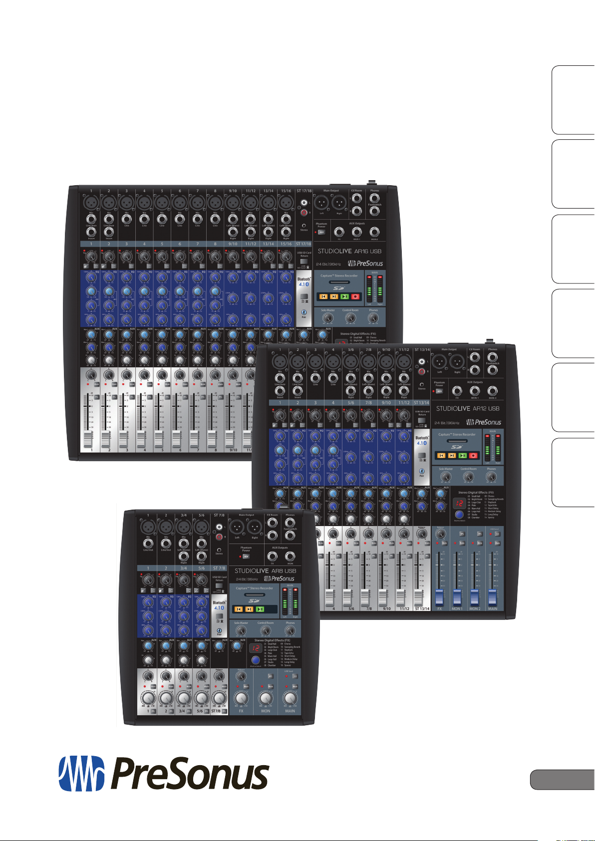
StudioLive™ AR-Series
Hybrid Digital/Analog Production Mixers
Owner’s Manual
OverviewSD Recording
Getting StartedResources
HookupTroubleshooting
and Playback
®
www.presonus.com
and Warranty
English
Page 2

Table of Contents
4 SD Recording and Playback — 18
1 Overview — 1
1.1 Introduction — 1
1.2 About This Manual — 1
1.3 Summary of Features — 2
1.3.1 Hardware Features — 2
1.4 What is in the Box — 3
1.5 What is in your My PreSonus Account — 3
2 Getting Started — 4
2.1 Level-Setting Procedure — 4
3 Hookup — 6
3.1 Connections and Controls — 6
3.1.1 Inputs — 6
3.1.2 Outputs — 7
3.1.3 Rear Panel Connections — 8
4.1 SD Recording — 18
4.2 SD Playback — 19
5 Resources — 20
5.1 EQ Frequency Guides — 20
5.2 Block Diagrams — 22
5.2.1 StudioLive AR12 and AR16 Block
Diagram — 22
5.2.2 StudioLive AR8 Block Diagram — 24
5.3 Recall Sheets — 26
5.3.1 AR16 and AR12 Track Sheet — 26
5.3.2 AR8 Recall Sheet — 28
5.4 Technical Specifications — 29
6 Troubleshooting
and Warranty — 32
6.1 Troubleshooting — 32
3.2 Channel Controls — 8
3.2.1 Digital Returns — 9
3.3 The Super Channel — 9
3.3.1 Pairing a Bluetooth Device — 10
3.4 Monitor Buses — 10
3.4.1 Monitor Bus Controls — 10
3.4.2 Creating Monitor Mixes — 11
3.5 Internal FX Bus — 12
3.5.1 Effects Presets — 12
3.5.2 Internal FX Bus Return — 13
3.5.3 Creating Internal Effects Mixes — 13
3.5.4 Using an External Effects Processor — 14
3.6 Master Section Controls — 15
3.7 Typical Band Setup Diagram — 16
3.8 Typical Home Studio Setup Diagram — 17
6.2 Warranty Information — 33
6.2.1 How Consumer Law Relates To This
Warranty — 33
Page 3
1 Overview
StudioLive™ AR Series Owner’s Manual
1.1 Introduction
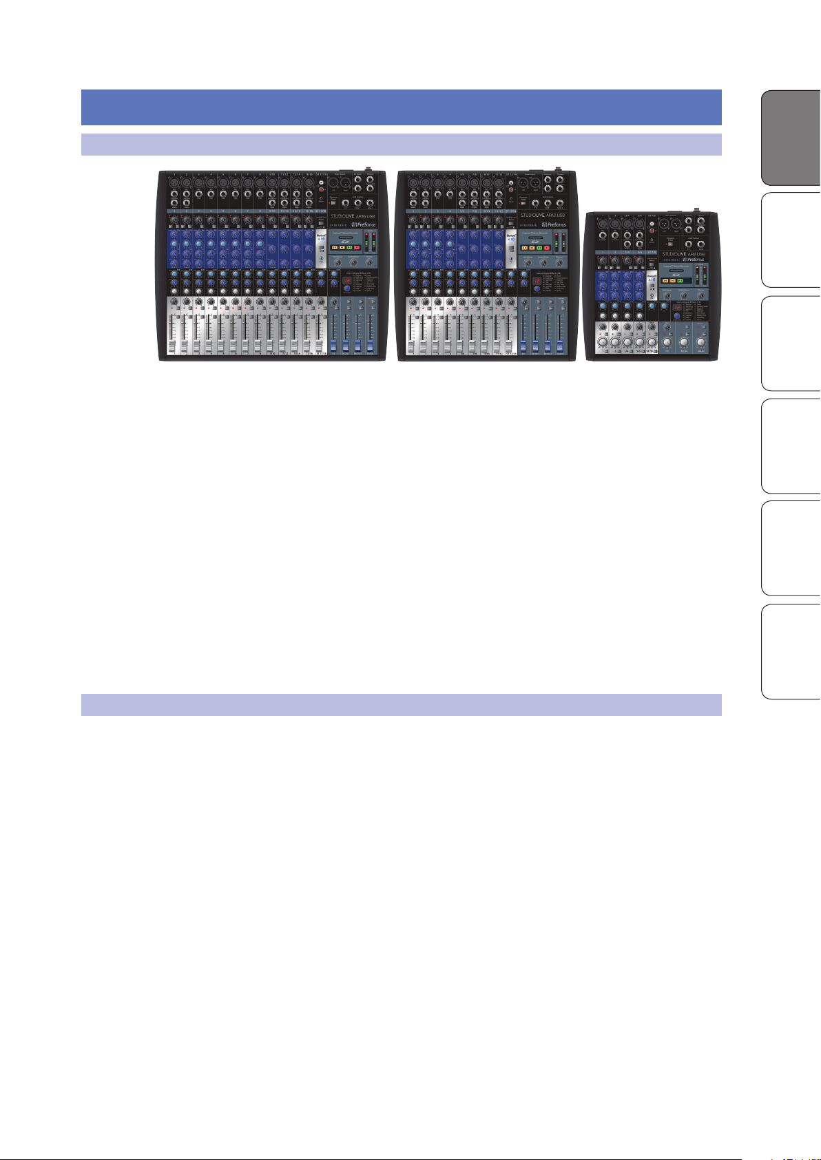
Thank you for purchasing a PreSonus® StudioLive™ AR-series mixer, the world’s
most advanced hybrid digital/analog production mixer. PreSonus Audio
Electronics has designed the StudioLive AR-series mixers utilizing high-grade
components to ensure optimum performance. Loaded with high-headroom
microphone preamplifiers; a built-in USB 2.0 recording and playback engine;
parametric EQ on every channel; onboard Bluetooth™ playback; integrated
stereo SD recording and playback; a multi-effects processor with a dedicated
mix bus; monitor mixes; extensive LED metering; and more, StudioLive AR
breaks new boundaries for live and studio performance and production. All you
need are a few microphones and cables, speakers, and your instruments, and
you are ready to mix and record in the studio or in front of a live audience!
We encourage you to contact us with questions or comments regarding
this product. PreSonus Audio Electronics is committed to constant
product improvement, and we value your suggestions highly. We believe
the best way to achieve our goal of constant product improvement is by
listening to the real experts: our valued customers. We appreciate the
support you have shown us through the purchase of this product.
For technical support, please see Section 6.1: Troubleshooting.
OverviewSD Recording
Getting StartedResources Overview
HookupTroubleshooting
and Playback
and Warranty
1.2 About This Manual
We suggest that you use this manual to familiarize yourself with the features,
applications, and connection procedures before using your StudioLive ARseries mixer. This will help you avoid problems during installation and setup.
This manual covers the hardware functions and features of all three StudioLive
AR-series mixers. When functional differences are called out, the AR16 USB
will be mentioned first, followed by the AR12 USB, and then the AR8 USB.
Information on using your StudioLive AR mixer as an audio interface,
as well as your licenses and installers for Capture™ and Studio One®
Artist, can be found in your My PreSonus user account.
Throughout this manual you will find Power User Tips. These tips provide
mixing tricks, some of which are unique to the StudioLive AR mixers,
as well as explanations of various audio terms. In addition, you will
find an assortment of audio tutorials throughout this manual.
Thank you, once again, for buying our product. We are confident
that you will enjoy your StudioLive AR mixer!
1
Page 4

1.3 Summary of Features
Overview
Overview SD Recording
Getting Started Resources
Hookup Troubleshooting
and Playback
and Warranty
1.3 Summary of Features
1.3.1 Hardware Features
• 18/14/8-channel mixer with 8/4/2 mono, 4/4/2
stereo, and one super stereo channel
• 12/8/4 high-quality microphone preamps with global 48V
• 2 instrument inputs
• 16/12/6 balanced line inputs
• 2 unbalanced inserts (AR16 USB and AR12 USB)
• 2 (L/R) RCA inputs
• 1/8-inch stereo input
• Highpass filter on every channel
• 3-band semi-parametric EQ
• 18/14/8x4 USB 2.0 audio interface
• Bluetooth playback
• 2x2 SD recorder
• Internal power supply
• Pan, mute, and PFL soloing on every channel
• XLR Main outputs
• Control Room outputs (stereo TRS, plus headphone)
• 2/2/1 Auxiliary monitor buses with TRS outputs and AFL soloing
• Dedicated effects bus with TRS output
• Onboard effects processor with 16 presets
• Stereo effects return
• Footswitch effects bypass
• 19-inch rack-mount kit (optional for AR16 USB and AR12 USB)
• Capture multitrack-recording application included
• Studio One Artist DAW included
2
Page 5
1.4 What is in the Box
Front Cover »»»
OverviewGetting Started
StudioLive™ AR-Series
Hybrid Digital/Analog Production Mixers
Quick Start Guide
StudioLive™ serie AR
Consolas híbridas digitales/analógicas para producción
Manual de usuario
StudioLive
™
AR-Series
Hybrider Digital/Analog-Produktionsmixer
Kurzanleitung
StudioLive
™
AR
Mélangeurs de production hybrides
numériques/analogiques
Guide de prise en main
www.presonus.com
English
Français
Español
Deutsch
R
®
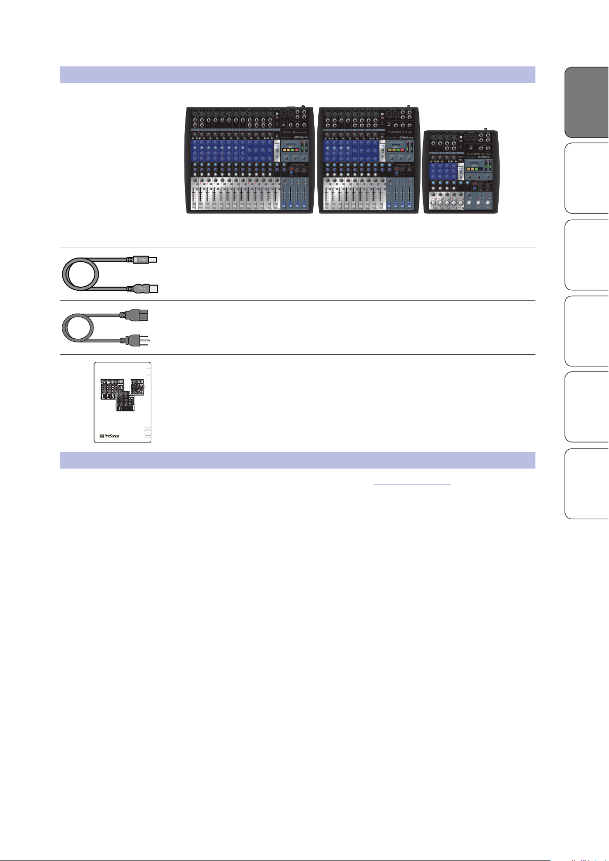
In addition to this manual, your StudioLive package contains the following:
• PreSonus StudioLive AR16 USB, AR12 USB, or AR8 USB
• 6-foot (1.8-meter), USB cable
• IEC power cord
• StudioLive AR-Series Quick Start Guide
hybrid digital/analog performance mixer
StudioLive™ AR Series Owner’s Manual
OverviewSD Recording
Getting StartedResources Overview
HookupTroubleshooting
and Playback
1.5 What is in your My PreSonus Account
Once you register your StudioLive AR mixer at My.PreSonus.com, you will
find the following software available for download in your user account:
• StudioLive AR-Series Owners Manual
• StudioLive AR-Series Software Reference Manual
• Capture multitrack-recording software
• Studio One Artist DAW software and bundled content
• ASIO drivers for Windows systems (Mac OS X users do not require a driver)
and Warranty
3
Page 6
2.1 Level-Setting Procedure
Overview SD Recording
Getting Started
Getting Started Resources
Hookup Troubleshooting
and Playback
2 Getting Started
Before you begin, here are a few general rules of thumb:
• Always turn down the Main, Control Room, and Phones
level controls before making connections.
• Before plugging or unplugging a microphone while other channels
are active, mute the channel to which you are connecting.
• Channel levels should be set on or near the “U” mark whenever possible. The
“U” indicates unity gain, meaning the signal is neither boosted nor attenuated.
• Do not allow your inputs to clip. Watch the signal indicators and make sure
the red Clip indication illuminates rarely, if ever. Clipping (overloading)
the inputs can result in digital distortion, which sounds terrible.
Warning: Engaging phantom power or connecting sources without muting the channels
can result in a very loud pop that can potentially damage your sound equipment.
Always mute your channels before engaging Phantom power or connecting sources.
P.A. and studio equipment should be powered on in the following order:
• Sound sources (keyboards, direct boxes, microphones,
etc.) connected to the StudioLive AR inputs
• StudioLive AR mixer
• Computer (if applicable)
• Power amplifiers or powered monitors
When it’s time to power down, your system should be turned off in the reverse
order. Now that you know what not to do, let’s get some audio going!
2.1 Level-Setting Procedure
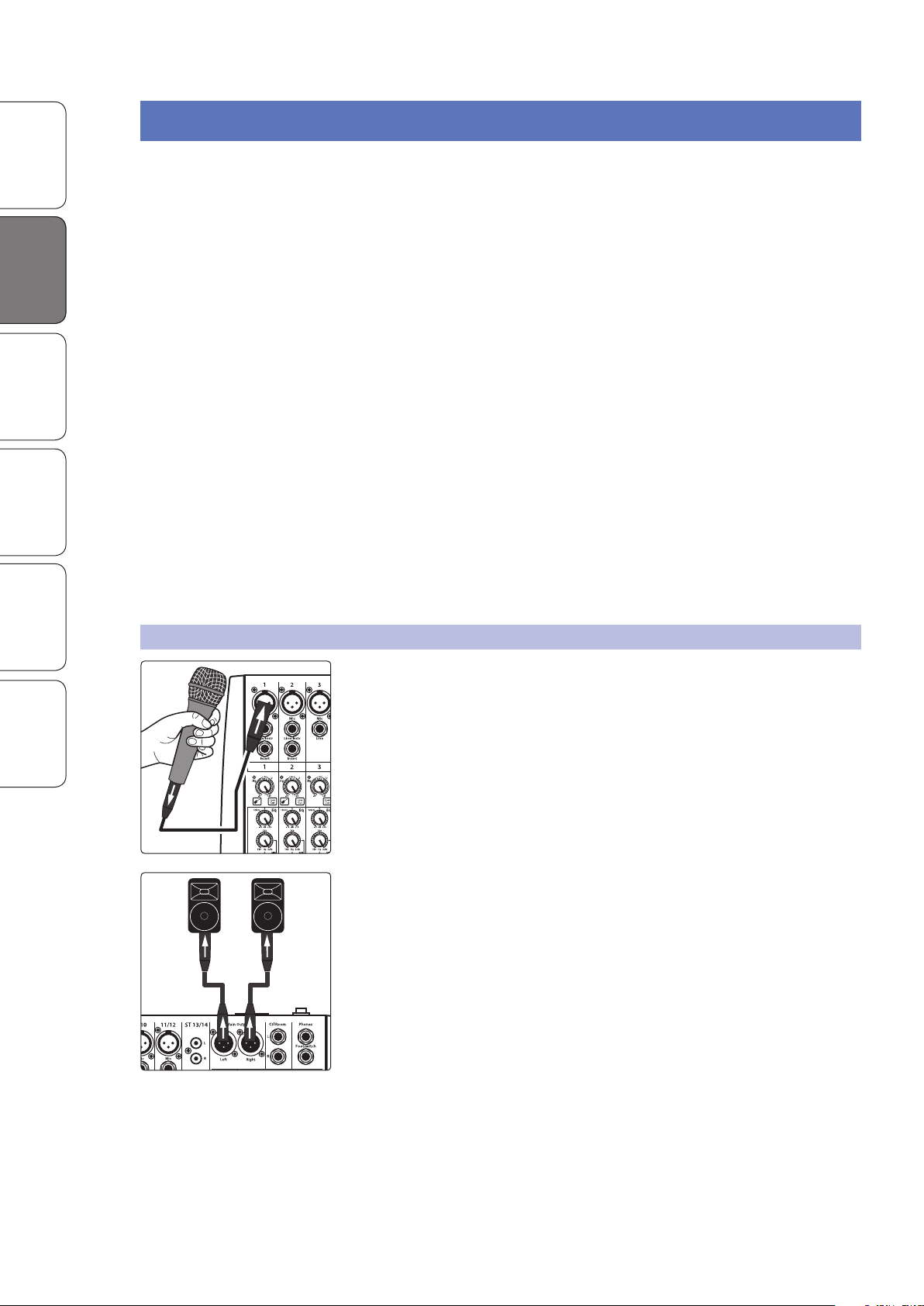
1. Grab a microphone and a mic cable and plug them into the
and Warranty
Channel 1 mic input.
2. Connect the Main outputs of your StudioLive AR to your power amplifier or
powered monitors.
3. Bring down all the level controls on your StudioLive AR to the lowest setting.
4. Make sure that the Mic/Line knob on Channel 1 is
turned all the way counter-clockwise.
5. Plug your StudioLive AR-series mixer into a power outlet and turn it on.
4
Page 7
StudioLive™ AR Series Owner’s Manual
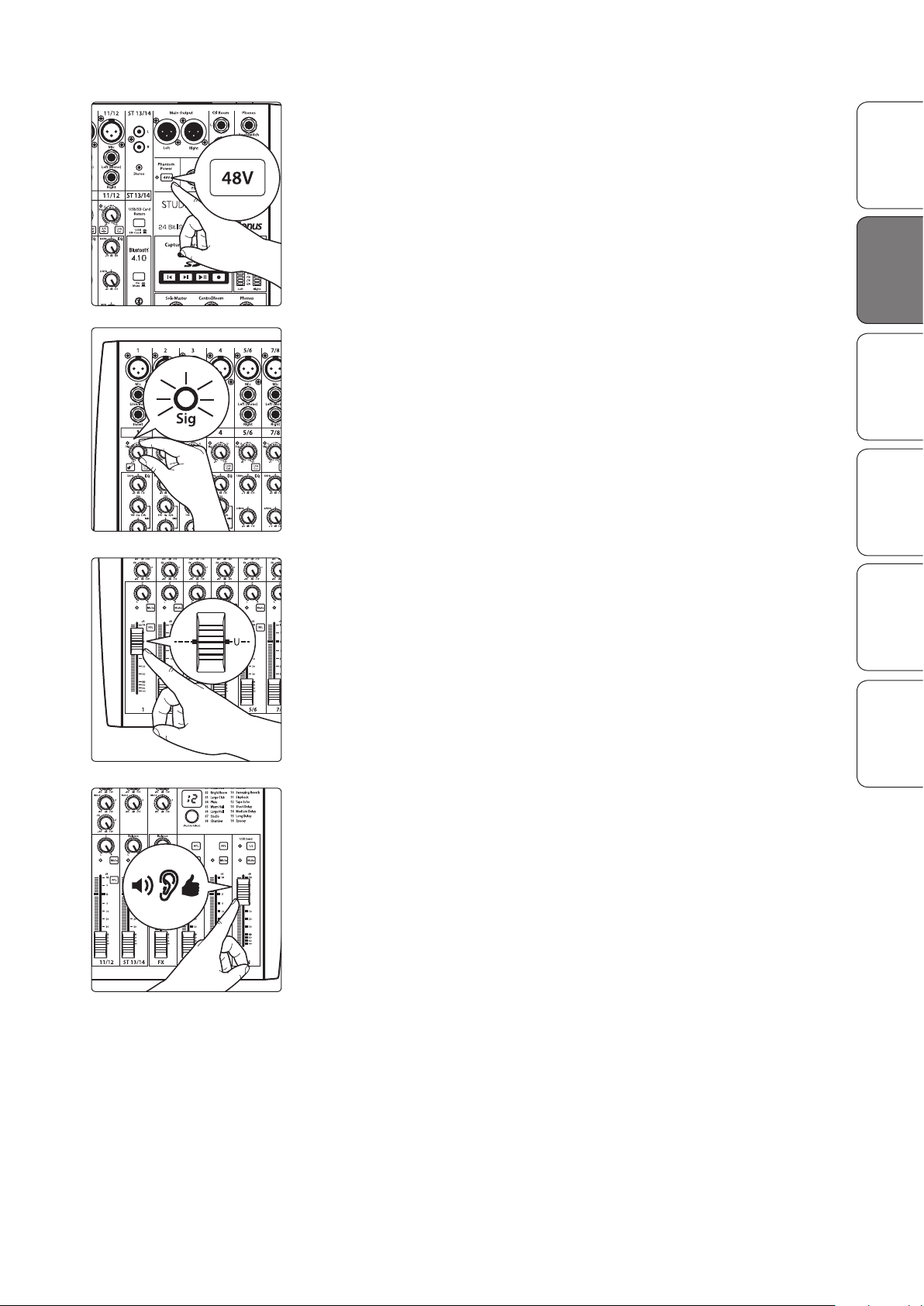
6. If your microphone requires phantom power, engage the 48V button on
your StudioLive AR mixer.
7. Turn on your amplifier or powered monitors.
8. Speak or sing into your microphone at approximately the same volume you
expect during the performance.
9. Turn the trim knob on Channel 1 clockwise while watching the signal
indicator. Adjust the Channel 1 trim knob until the signal/clip indicator is
red, then back down until it is green and just below clipping at the loudest
input level.
OverviewSD Recording
Getting StartedResources Getting Started
HookupTroubleshooting
and Playback
10. Raise the Channel 1 level control to unity gain (denoted with a “U”).
11. Bring up the Main level until you can comfortably listen to your microphone
through your speakers.
12. Sculpt the sound by adding EQ to taste.
and Warranty
5
Page 8
3.1 Connections and Controls
Overview SD Recording
Getting Started Resources
Hookup Troubleshooting
HookupHookup
and Playback
and Warranty
3 Hookup
3.1 Connections and Controls
3.1.1 Inputs
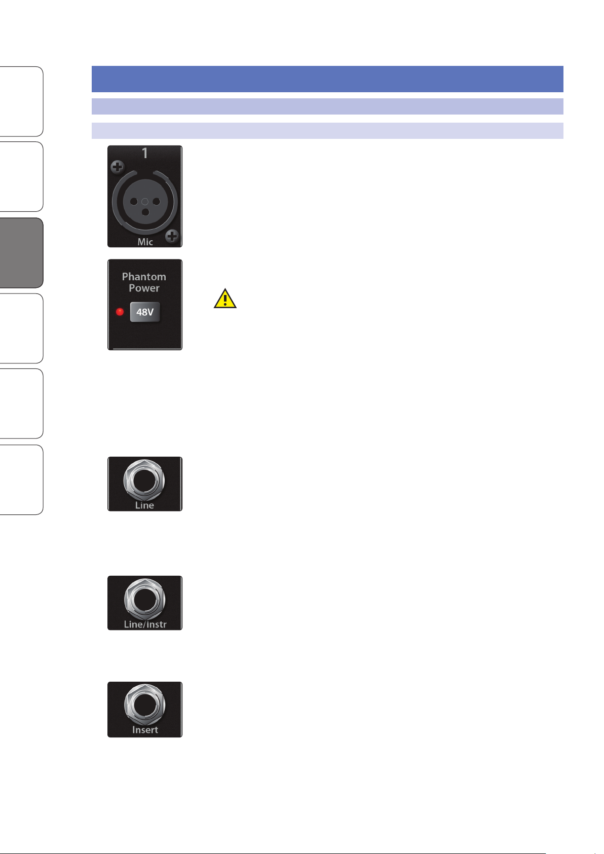
Microphone Inputs. Your StudioLive AR-series mixer is equipped with high-quality
microphone preamplifiers for use with all types of microphones.
48-volt Phantom Power. The StudioLive AR mixers provide global 48V phantom
power for all microphone inputs.
WARNING: Phantom power is required for condenser microphones but can
severely damage some dynamic mics, especially ribbon mics. Therefore, unless
the manufacturer of your dynamic mics clearly states that phantom power will not
damage them, you should use condenser mics only, with phantom power on, or
dynamic mics only, with phantom power off.
Power User Tip: Dynamic microphones and ribbon microphones are generally
lower-output devices and require no external power source. The most important
thing to note about ribbon microphones is that they very rarely require phantom
power. In fact, unless a ribbon microphone calls specifically for phantom power,
sending phantom power to it can cause severe damage. Condenser microphones
are generally more sensitive than dynamic and ribbon microphones and typically
require external +48V phantom power. Always review your microphone’s
documentation to ascertain the manufacturer’s recommended operating practices.
Line-level Inputs. Each channel of your StudioLive AR-series mixer has a ¼-inch,
balanced TRS connection for line-level input. Typical examples of line-level
connections are synthesizer outputs, CD/DVD-player outputs, and (with exceptions)
signal-processor inputs and outputs.
Note: As with any mixer, plugging in a microphone or a line-level input device, or
turning phantom power on or off, will create a momentary spike in the audio output
of your StudioLive AR mixer. Because of this, it is highly recommended that you mute
or turn down the channel trim before changing connections or turning phantom
power on or off. This simple step will add years to life of your audio equipment.
Instrument Inputs. Channels 1 and 2 are equipped with an input that can be
switched between line and instrument. Use these ¼-inch connections for
instruments that don’t have internal preamps (guitar, bass, etc.). See Input Source
button in Section 3.2 for more information.
Power User Tip: Active instruments have an internal preamp and a line-level
output. This type of instrument should be plugged into a line input, rather than
an instrument input. Plugging a line-level source into an instrument input risks
damage to the input and results in a very loud and often distorted audio signal.
Insert (AR16 USB and AR12.USB). Channels 1 and 2 on the StudioLive AR16 USB
and AR12 USB are equipped with a direct-insert point. These unbalanced, ¼-inch
connectors can be used to connect external processors (such as compressors, EQs,
de-essers, and filters) to the channel inputs.
6
Page 9
3.1.2 Outputs
Tip
(Return)
Tip
(Send)
To mixer
channel
insert
From
processor
output
To
processor
input
Tip
(Out)
Ring (In)
Ring
(Return)
Tip
(Send)
StudioLive™ AR Series Owner’s Manual
Insert-connector wiring:
Tip = send (output to inserted device)
Ring = return (input from inserted device)
Sleeve = common ground
OverviewSD Recording
Getting StartedResources HookupHookup
1 2
3
4
5
6
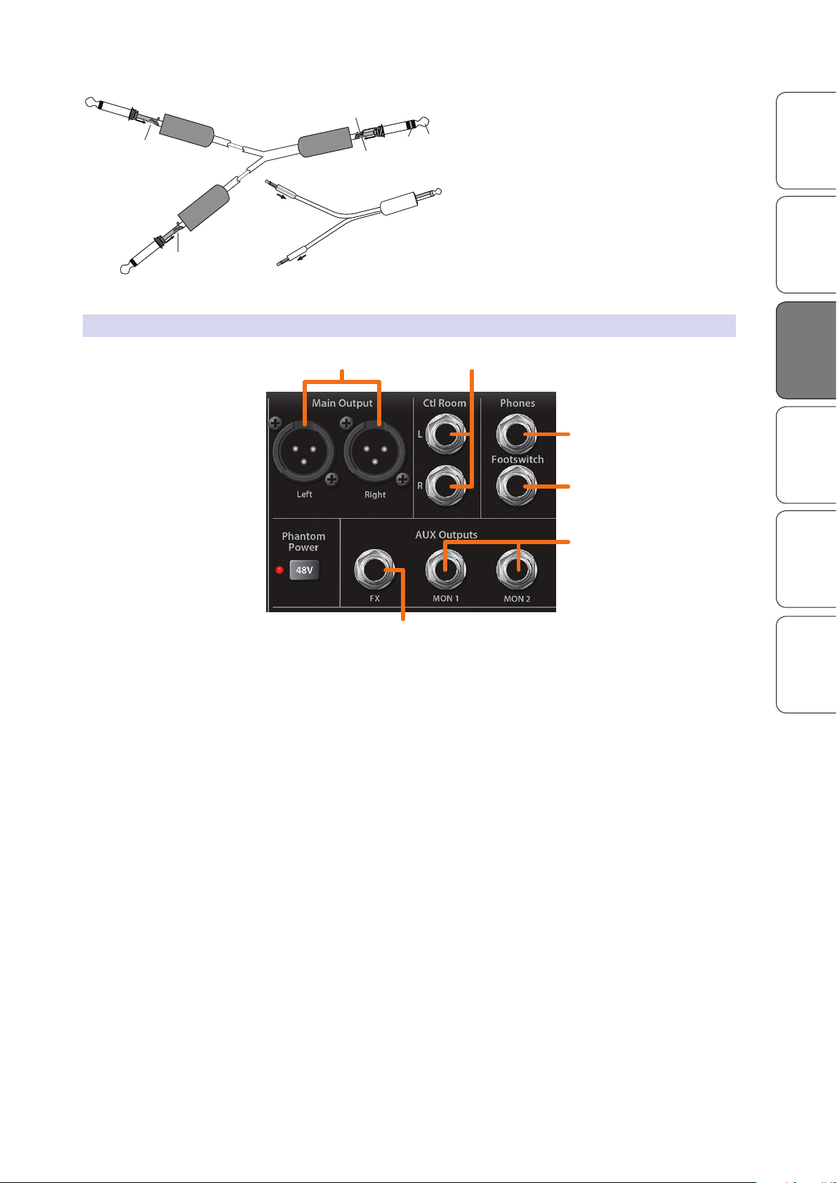
1. Main. The StudioLive AR-series mixers feature with XLR main outputs.
2. Control Room. These are the balanced control-room outputs.
The Control Room knob on the top panel controls the level.
3. Phones. This ¼-inch TRS connection is for use with headphones.
The Phones knob on the top panel controls the level.
HookupTroubleshooting
and Playback
and Warranty
4. Footswitch. Your StudioLive will follow the behavior
of the type of footswitch you use.
5. Monitor. The StudioLive AR-series mixers are equipped with 2/2/1 monitor
mix (Mon) outputs. Monitor mixes are routed to these outputs. See Section
3.4 for more information on creating monitor mixes for monitoring.
6. FX. The FX send mix is routed to this output, allowing you to create
an additional monitor mix. When this output is engaged, the internal
effects processor is bypassed. More information about creating effects
mixes and the effects processor can be found in Section 3.5.
7
Page 10
3.2 Channel Controls
1
3 4
2
5
6
7
8
9
10
11
12
13
14
Overview SD Recording
Getting Started Resources
Hookup Troubleshooting
HookupHookup
and Playback
3.1.3 Rear Panel Connections
USB 2.0 port. Use this port to connect your StudioLive AR-series mixer to a USB port
on your computer when using the mixer as an audio interface. See your StudioLive
AR-series Software Reference Manual for further information.
Power-input. Plug in the provided IEC power cable here.
Power switch. Push the top part of the switch ( | ) to turn on your StudioLive AR
mixer. Push the bottom part of the switch ( O ) to turn it off.
3.2 Channel Controls
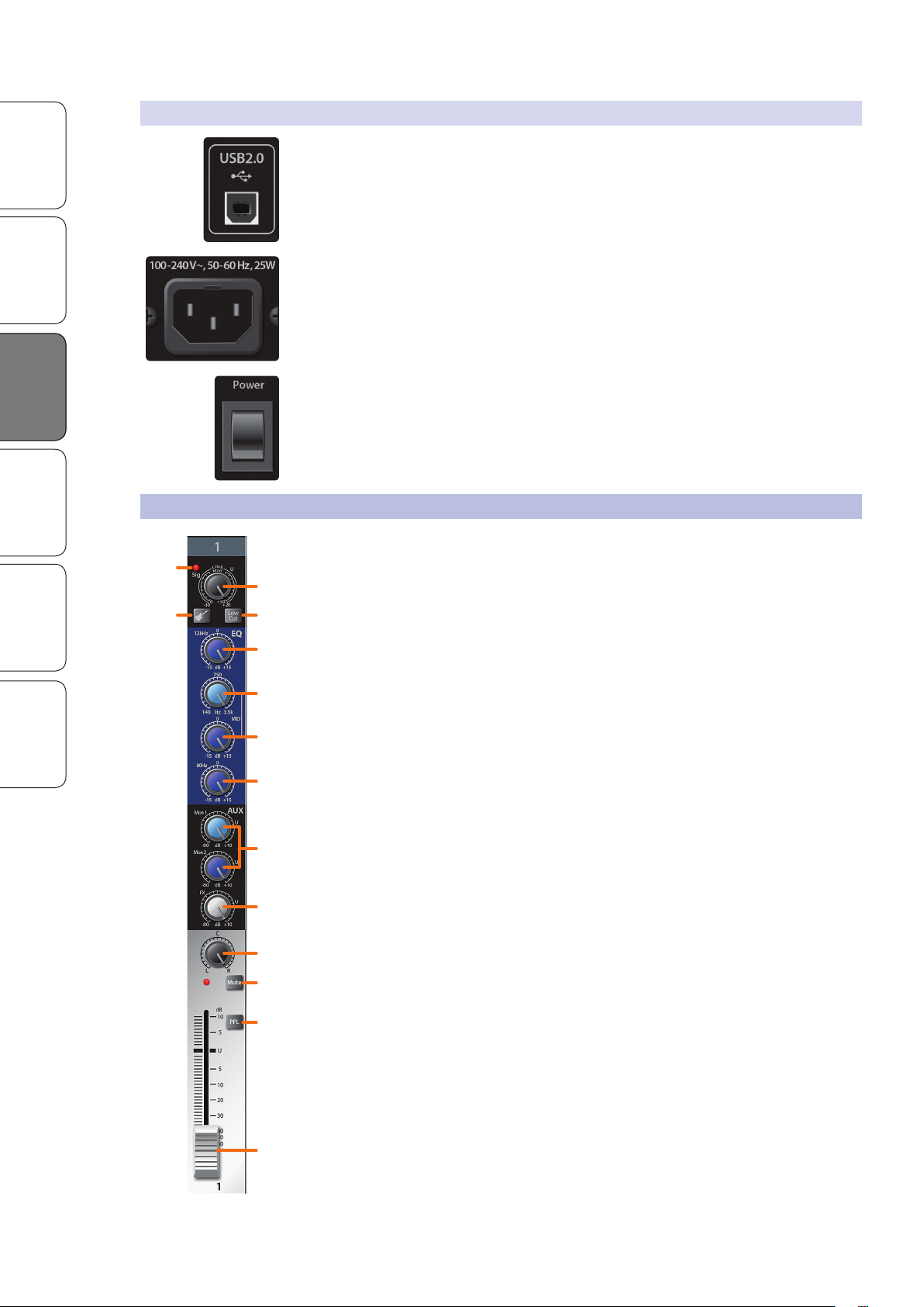
1. Input-signal indicator. Each channel features an LED next to the trim control that
illuminates green whenever an input signal is present. The LED color will change to
red if the signal (pre- or post-EQ) reaches -3 dB.
and Warranty
2. Input Gain control. These knobs provide 50 dB of variable gain for mono
channels (0 to +50 dB mic/instrument, -20 to +30 dB line) and 40 dB of variable
gain for stereo channels (+5 to +45 dB mic/instrument, -15 to +25 dB line).
3. Input Source button. Channels 1 and 2 offer an Input Source button
that lets you select instrument- or line-level for the ¼-inch inputs
on these channels. Press this button to engage the instrument
preamp when connecting guitars or a passive bass.
Note: Engaging the Instrument preamp will disable the
microphone preamp on the XLR connection.
4. Low Cut filter. When engaged, all frequencies below 100 Hz
will be attenuated (cut) at a slope of -18 dB/octave.
Power User Tip: Use the Low Cut filter to remove unwanted low-frequencies
from your source signal, rather than trying to EQ them out.
5. High shelving EQ Gain control. Sets the level of the high-
band center frequency (12 kHz) from -15 to +15 dB.
Power User Tip: A high shelving EQ is like a treble-control knob on a stereo. In
this mode, the Center Frequency control selects the shelving frequency.
6. Mid peaking EQ frequency control (AR16 USB and AR12 USB). Sets the
center frequency of the Mid EQ. You can adjust the center frequency from
140 Hz to 3.5 kHz. This control is available on the Mono input channels only.
7. Mid peaking EQ gain control. Sets the level of the mid-band
center frequency from -15 to +15 dB. The center frequency can
be adjusted on the mono inputs of the AR16 USB and AR12 USB.
All other inputs have fixed center frequency at 2.5 kHz.
8. Low shelving EQ gain control. Sets the level of the low-
band center frequency (80 Hz) from -15 to +15 dB.
Power User Tip: A low shelving EQ is like a bass-control knob on a stereo. In
this mode, the Center Frequency control selects the shelving frequency.
8
Page 11
StudioLive™ AR Series Owner’s Manual
1
2
3
4
5
9. Monitor sends. These are the level controls for each channel to the
corresponding monitor mix. The AR16 USB and AR12 USB provide
two monitor mixes, and the AR8 USB provides one monitor mix.
See Section 3.4 for more information on creating monitor mixes.
10. FX send. This is the level control for each channel for the effects mix.
See Section 3.5 for more information on creating effects mixes.
11. Pan. This sets the channels position in the Main stereo mix.
Power User Tip: Panning can be a great way to achieve better separation
in your main mix. Using pan in conjunction with level will allow you to
create more definition and space between each channel’s signal.
12. Mute button and indicator. This button mutes its channel in all outputs.
The LED to the left of it will illuminate red when the channel is muted.
OverviewSD Recording
Getting StartedResources HookupHookup
13. PFL (Pre-Fader Listen) button. This button will solo its channel to
the Control Room and Headphone outputs, pre-fader. When no PFL
button is engaged, the Main mix is routed to these outputs.
Power User Tip: If you can’t hear the main mix or a channel in your
headphones, make sure that PFL is not engaged on an unused channel.
14. Channel level. Controls the overall level of the channel.
3.2.1 Digital Returns
The last stereo channel (15/16, 11/12, 5/6) provides a digital playback streaming
option. The Digital Return button routes playback streams 3 and 4 from your audio
software to this channel. When engaged, the analog source will be bypassed;
however, the signal will still be routed to the digital send so that it can be recorded or
processed by a plug-in. For more information, see your StudioLive AR-series Software
Reference Manual in your My PreSonus account.
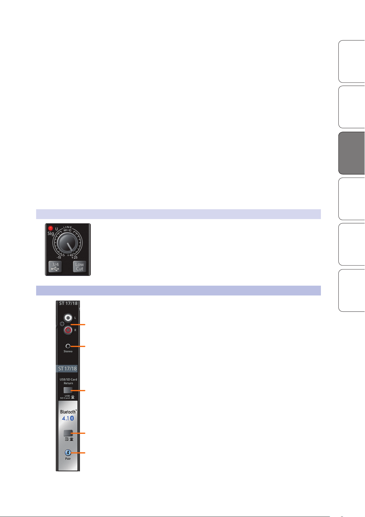
3.3 The Super Channel
Each StudioLive AR-series mixer features a unique Super Channel that allows you to
connect several analog and digital sources at once so you can get the most out of
your mixer.
1. RCA inputs. These unbalanced inputs allow you to connect a stereo
line-level device, such as a Blu-ray player or karaoke machine.
HookupTroubleshooting
and Playback
and Warranty
2. 1/8-inch stereo input. This is an unbalanced, stereo, 1/8-inch
connection for line-level devices such as smartphones and tablets.
3. USB / SD Card Return. By default, playback for the onboard SD recorder is
routed to the Super Channel. Engaging this button will route USB playback
streams 1-2 to the Super Channel instead. More information on using
your StudioLive AR-series mixer as an audio interface can be found in the
StudioLive AR-series Software Guide in your My PreSonus user account.
4. Bluetooth On/Off. By default, Bluetooth playback is muted. Engaging this
button will allow you to play audio through the Super Channel wirelessly.
5. Bluetooth pairing. Use this button to pair your Bluetooth device with
your AR-series mixer. See Section 3.3.1 for pairing instructions.
Power User Tip: All available sources are summed into the Super Channel. Because this
channel only selects line-level devices, the majority of which have onboard level controls,
you can use this channel to expand the input flexibility of your StudioLive AR-series mixer.
9
Page 12
3.4 Monitor Buses
Hold 3 sec
3
2
1
Overview SD Recording
Getting Started Resources
Hookup Troubleshooting
HookupHookup
and Playback
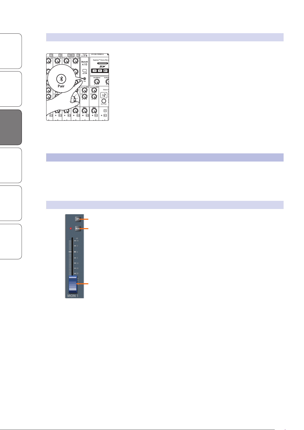
3.3.1 Pairing a Bluetooth Device
To pair a new device to your StudioLive AR-series mixer:
1. Press and hold the Bluetooth pairing button for three seconds.
2. The Bluetooth button will flash once every second.
3. Search for new Bluetooth devices from the device to
which you’d like to pair (smartphone, tablet, etc).
4. Select “StudioLive AR16/12/8 USB” from the available
Bluetooth devices list on the pairing device.
5. The Bluetooth button will illuminate solid when paired successfully.
Note: If previously paired, your StudioLive AR mixer will connect
automatically. The Bluetooth pairing button will flash rapidly (two to
three times per second) while the Bluetooth module detects connected
devices and will illuminate solid when it is successfully paired.
3.4 Monitor Buses
The monitor bus provides outputs to route auxiliary mixes that are separate
from the main mix. StudioLive AR-series mixers are equipped with 2/2/1 monitor
buses, which have physical output jacks, and one internal effects bus.
Monitor buses can be used for many applications, the two most common of which
are creating monitor mixes and inserting external effects processors into the mix.
3.4.1 Monitor Bus Controls
1. AFL button. This button will solo the aux bus to the monitor outputs after the
fader.
and Warranty
Power User Tip: Using this control to listen in on a performer’s monitor
mix can be a great way to quickly dial in just the right amount of
each signal and get to a great monitor mix more quickly.
2. Mute button. This button will mute or unmute its monitor bus. The LED
to the left of it will illuminate red when the monitor output is muted.
Power User Tip: Muting a monitor mix output during performance breaks is
a quick and easy way to prevent accidental signal spikes or feedback.
3. Output level. Adjusts the master level of the Monitor output.
10
Page 13
3.4.2 Creating Monitor Mixes
Creating custom monitor mixes is critical. If musicians can’t hear themselves or their
bandmates, their performances will suffer. A monitor mix can be mono or stereo.
Most often, an individual live monitor mix is mono and is sent to a floor-wedge or
sidefill monitor. (The obvious exception is in-ear monitor systems.) A studio monitor
mix is usually stereo because it is sent to a headphone amplifier that requires both a
left- and a right-channel input. In both cases, the function of the aux bus is the same.
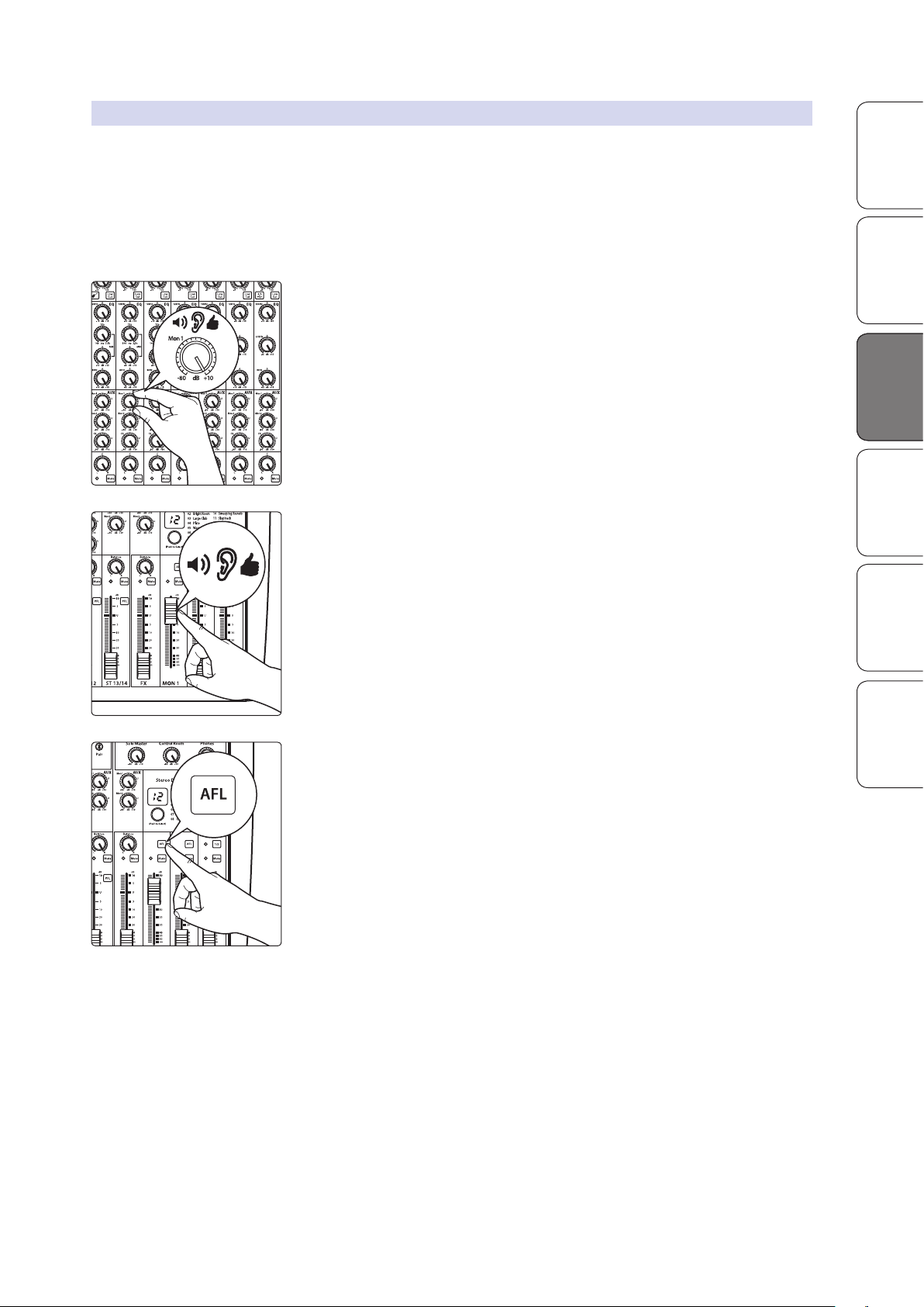
As an example, let’s create a mono mix for Monitor Bus 1:
1. The Mon 1 send control for each channel sets the send level in the Mon 1
StudioLive™ AR Series Owner’s Manual
mix. Use these knobs the same way that you use the output level controls to
dial in your main mix. Ask your musicians what they would like in their
monitor mix and use their requests as a starting point.
OverviewSD Recording
Getting StartedResources HookupHookup
HookupTroubleshooting
2. Use the Mon 1 Output control to adjust the overall output level.
3. Press the Mon 1 AFL button to listen to the mix through the headphone or
control room outputs as you make final adjustments to the mix.
and Playback
and Warranty
11
Page 14

3.5 Internal FX Bus
Overview SD Recording
Getting Started Resources
Hookup Troubleshooting
HookupHookup
and Playback
and Warranty
3.5 Internal FX Bus
Each StudioLive AR-series mixer is equipped with an internal effects
processor with 16 effects presets. This section will cover each
preset, as well as how to add and use effects in your mix.
3.5.1 Effects Presets
To select an effects preset, simply turn the encoder until the
desired preset number is displayed and press the encoder.
Preset Descriptions and Uses
No. Name Description When to Use
1 Small Hall
2 Bright Room
3 Large Club
4 Plate Reverb
5 Warm Hall
6 Large Hall Provides long pre-delay and reverb time
7 Studio
8 Chamber
9 Chorus
Adds a medium reverb time to emulate a
small concert hall
Emulates the sound of large room with hard
surfaces to provide many early reflections
Warm and full reverb to emulate the sound of
a large acoustic venue
Emulates a vintage plate reverb by providing
many early reflections without pre-delay
Emulates a large concert hall with
softer surfaces
Emulates an acoustically treated studio room
to provide a more intimate and warmer tone
Emulates a large cathedral by adding long
pre-delays and reflections
Plays with the phase of the signal to create a
modulated, sweeping effect
• Gives vocals and instruments a “big” vibe
• Adds a greater sense of space
• Adds life to a flat room
• Helps a vocal or instrument stand out in
a mix
• All purpose reverb for overall mixes
• Fattens up percussion and backing vocals
• Adds rich fullness to acoustic instruments
and solo vocals
• Gives acoustics instruments and vocals a
“larger than life” feel
• Soften harsh instruments
• Gives vocals a lush vibe
• Adds subtle ambience to a mix
• Adds a rich, ethereal feel to any instrument
• Good effect for electric guitar and keyboards for a vintage vibe
10 Sweeping Reverb Adds a rich reverb to a chorus effect • Thickens and enhances instruments
Adds a single, relatively quick delay of the
11 Slapback
12 Tape Echo
13 Short Delay Provides 300 ms delay • Helps a vocal or guitar cut through a mix
14 Medium Delay Provides 380 ms delay • Adds drama to a vocal or sample
15 Long Delay Provides 480 ms delay
16 Spacey
original signal to emulate vintage tape-
based delay units
This medium-length, clean delay emulates
the traditional tape echo
Combines a large room reverb with
a long delay
• Vintage sound for guitars
• Fun effect for vocals
• Great for vocals and guitars for a retro vibe
• Subtle, dreamy effect for vocals and
instruments
• Because Purple Rain
12
Page 15
3.5.2 Internal FX Bus Return
4
3
2
1
TURN, THEN PRESS
TO SELECT
The internal FX return allows you to adjust the amount of the effects
output you would like in your main and monitor mixes.
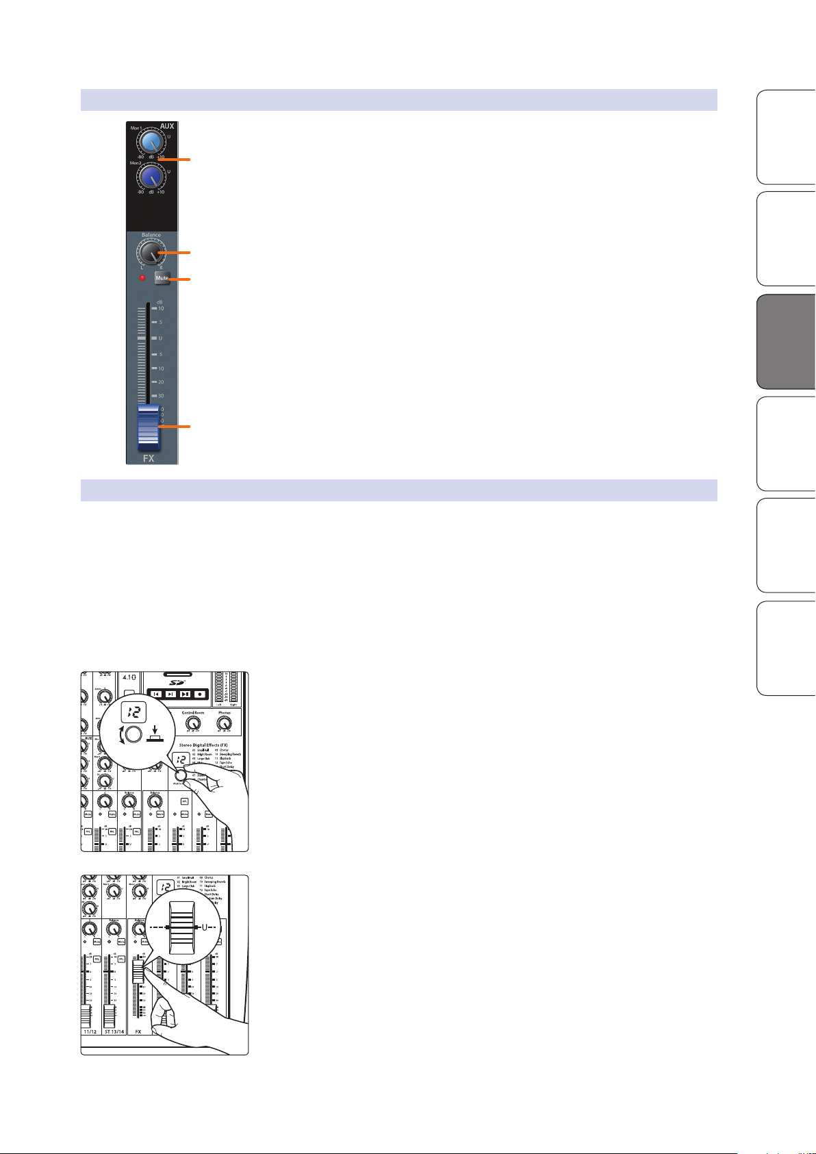
1. Monitor sends. These are the level controls for the effects output in each monitor
mix. The AR16 USB and AR12 USB provide two monitor mixes; the AR8 USB
provides one monitor mix. See Section 3.4.2 for more information on creating
monitor mixes.
2. Balance. This sets the FX return’s position in the main stereo mix.
3. Mute button. This button will mute or unmute the FX return. The LED to
the left of it will illuminate red when the monitor output is muted.
Power User Tip: Mute the FX return during performance breaks while the
band is speaking to the audience to create a more professional show.
4. FX level. Adjusts the master level of the effects output in your main mix.
StudioLive™ AR Series Owner’s Manual
OverviewSD Recording
Getting StartedResources HookupHookup
HookupTroubleshooting
3.5.3 Creating Internal Effects Mixes
There are at least two main advantages to creating an effects mix, rather than
inserting an effect in a channel. First, several channels can be sent to a single
processor. In addition to greatly simplifying the number of parameters you
have to control, this can create a cohesive sound in your mix. The second
advantage of creating an effects mix is that you can vary the level sent from
each channel to the processor, rather than patching the output directly into the
effect. This allows you to add a lot or a little of an effect to any given channel.
Your StudioLive AR-series mixer’s internal effects bus is used much in
the same way the monitor buses are used to create monitor mixes.
1. To begin, select the effects preset you would like to use by turning the
and Playback
and Warranty
Effects encoder to the desired number and pressing the encoder.
2. Raise the FX return output level to unity.
13
Page 16
Overview SD Recording
Getting Started Resources
Hookup Troubleshooting
HookupHookup
3.5 Internal FX Bus
3. Use the FX send controls on each channel the same way that you use the
faders to set the output level to your main mix. The higher a channel’s level
is in the effects mix, the more processed (“wetter”) it will sound.
Let’s say that you are using reverb to liven up a relatively dead room.
You might send a little bit of each input to the reverb, but you probably
will not want much of the drums and bass to be processed, as too
much reverb could reduce their impact and leave your mix without
a sturdy foundation. So rather than turning the FX-send level for the
kick drum channel all the way up, turn it to the 8 or 9 o’clock position,
so that its saturation is between 20% and 30%. This way, only a small
portion of the kick-drum input will be affected by the reverb.
4. Use the FX return level fader to increase or decrease
the overall effects mix in the Mains to taste.
5. To send the FX return mix to a monitor mix, adjust the
FX return’s monitor send control to taste.
3.5.4 Using an External Effects Processor
and Playback
and Warranty
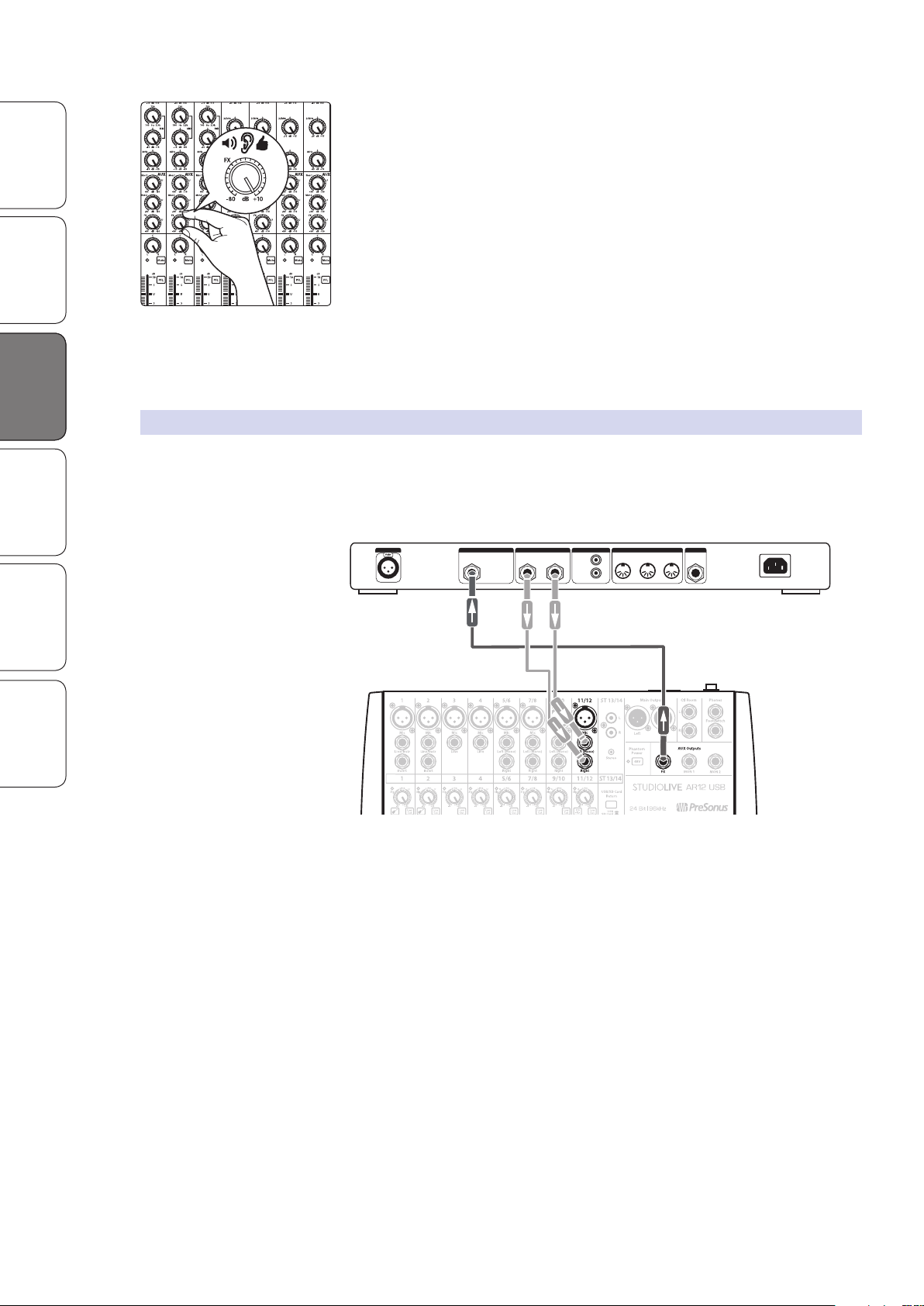
This section will detail how to use an external effects processor,
bypassing your StudioLive AR mixer’s internal processor.
1. To begin, connect the FX output to the input of your external effects processor and
connect the outputs of your processor to a stereo channel on your StudioLive AR.
LINE INPUTMIC INPUT BALANCED OUTPUTS MIDI PEDALDIGITAL I/O
MONO
Balanced Input
LEFT RIGHT
IN INTHRU OUT
DI
S/PDIF
DO
2. Turn up the output level of the stereo channel to unity.
3. Use the FX send controls on each channel the same way that you use the
faders to set the output level to your main mix. The higher a channel’s
level is in the effects mix, the more processed (“wetter”) it will sound.
4. Use the stereo channel’s Level control to increase or decrease
the overall effects mix in the Mains to taste.
5. To send the FX return mix to a monitor mix, adjust the
stereo channel’s monitor send control to taste.
Power User Tip: You can also use the FX output to create an additional monitor mix
when multiple monitor mixes are of greater importance than adding effects.
14
Page 17
3.6 Master Section Controls
3
2
1
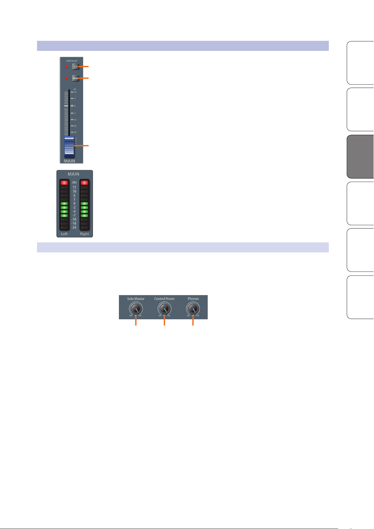
1. USB 1-2 Send. By default, the main mix can be recorded to your computer on the
last USB send pair (15-16/13-14/7-8). If you are only recording the main mix on
your computer, engaging the USB 1-2 Send button will simplify setup in most
situations.
Note: When this button is enabled, Channels 1 and 2 cannot be recorded
individually, although they will still be a part of the Main mix.
2. Main Mute button. This button will mute or unmute the Main bus. The LED
to the left of it will illuminate red when the main outputs are muted.
Power User Tip: Muting the main mix during performance breaks is a
quick and easy way to prevent accidental signal spikes or feedback.
3. Output-level control. Adjusts the master level of the Main output.
4. Main output meters. These peak meters display the output levels of the main
stereo bus. These meters are scaled from -24 to +15 dBu. For best performance, the
highest level of your mix should stay between the “0” and “+6” indicators.
StudioLive™ AR Series Owner’s Manual
OverviewSD Recording
Getting StartedResources HookupHookup
HookupTroubleshooting
and Playback
3.6.1 Control Room Levels
StudioLive AR-series mixers feature a headphone output and controlroom outputs, allowing you to listen to the main mix and the Solo
bus. Whenever a channel is soloed, it will automatically be routed
to the control room and headphone outputs. When no channel is
soloed, the main mix will be heard through these outputs.
1. Solo Master knob. Adjusts the overall level of the Solo bus.
2. Control Room knob. Adjusts the overall level of
the control-room monitor outputs.
3. Phones knob. Adjusts the overall level of the headphone output.
and Warranty
1 2 3
15
Page 18
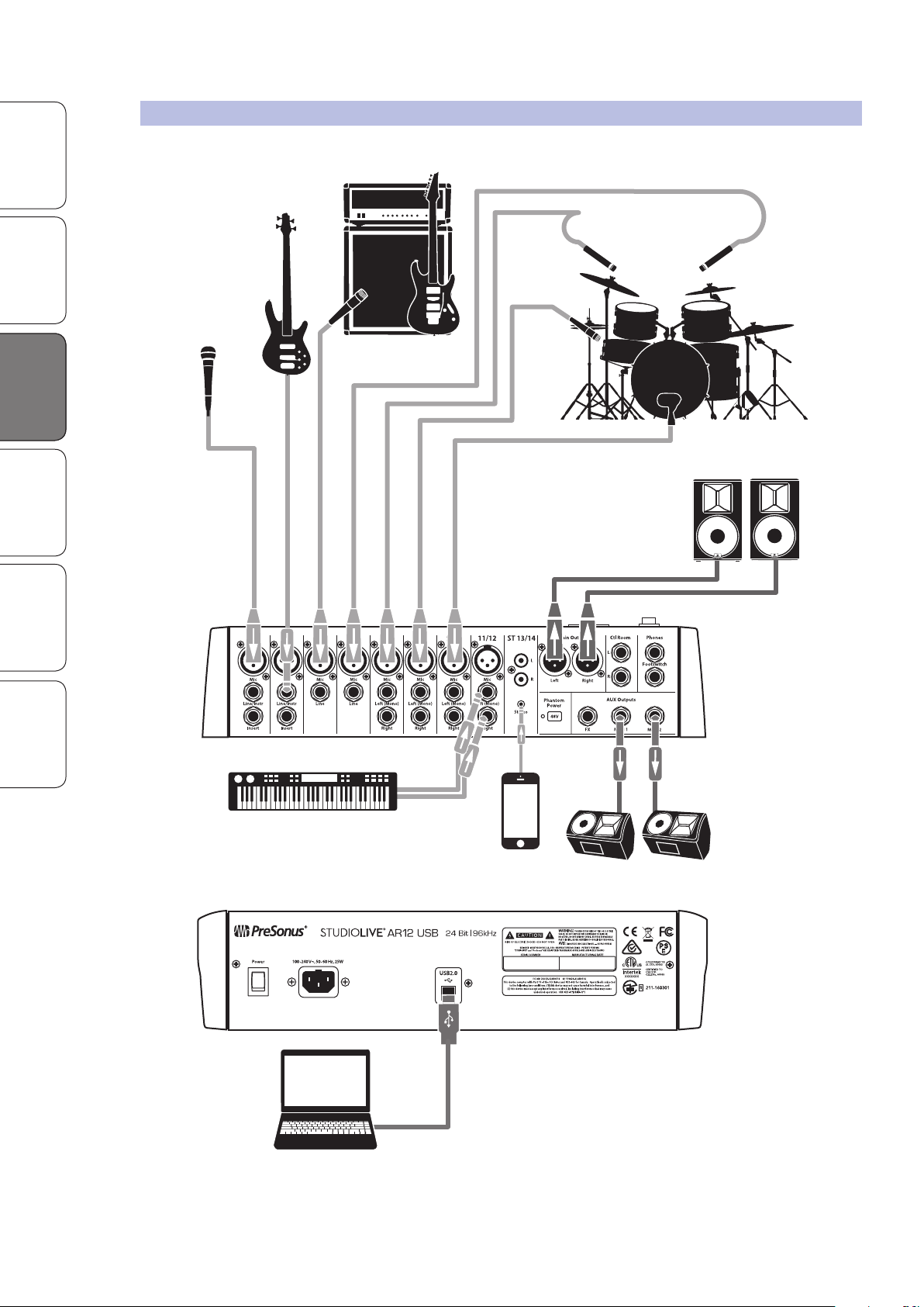
3.7 Typical Band Setup Diagram
Front of house
speakers
Floor wedges
Keyboard
Lead vocal
Drum kit
Bass
Electric guitar amp
Music
Playback
Laptop running Capture
Overview SD Recording
Getting Started Resources
Hookup Troubleshooting
HookupHookup
and Playback
3.7 Typical Band Setup Diagram
and Warranty
16
Page 19
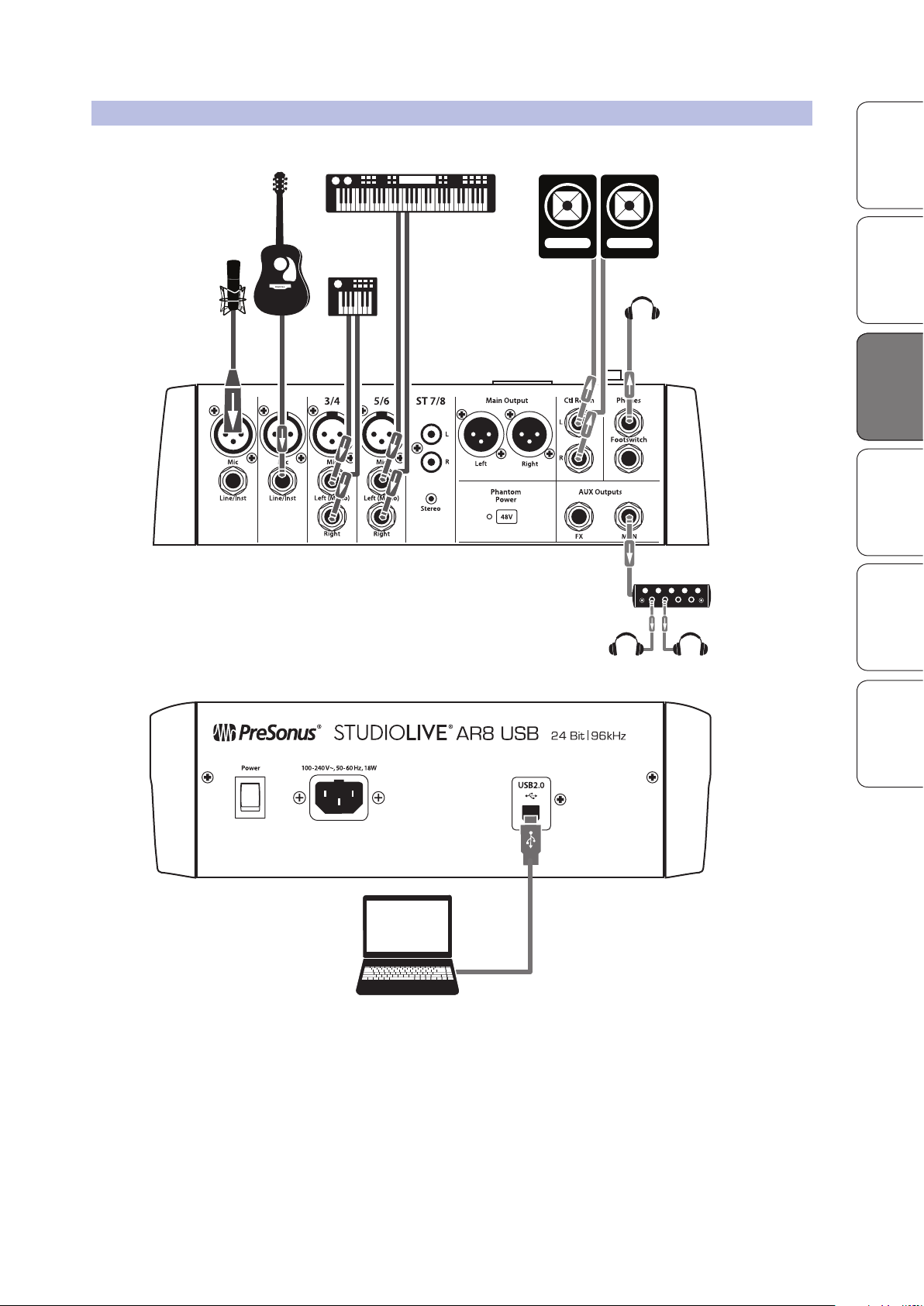
3.8 Typical Home Studio Setup Diagram
Laptop running Studio One
or 3rd party DAW
Mic
Guitar
Micro-synth
Keyboard Main reference
Phones
Phones
Headphone amp
StudioLive™ AR Series Owner’s Manual
OverviewSD Recording
Getting StartedResources HookupHookup
HookupTroubleshooting
and Playback
and Warranty
17
Page 20
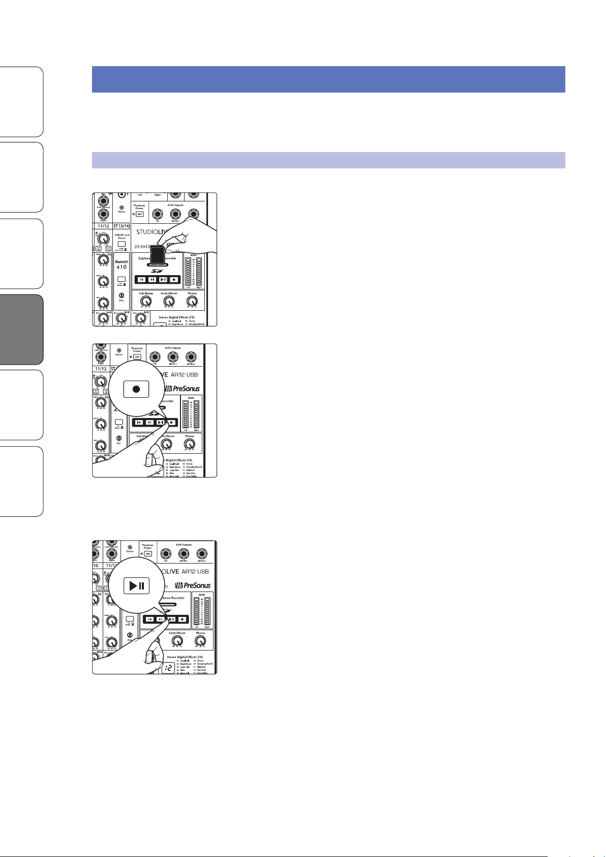
4.1 SD Recording
SD Card
Overview SD Recording
Getting Started Resources
Hookup Troubleshooting
and Playback
SD Recording
and Playback
and Warranty
4 SD Recording and Playback
StudioLive AR-series mixers are equipped with an onboard stereo SD recorder
that allows you to record the main mix as a stereo WAV file to any FAT16formatted SD card or FAT32-formatted SDHC card. You can also load stereo
WAV and MP3 files onto an SD or SDHC card to play audio during a show.
4.1 SD Recording
This section explains on how to record the main mix as a stereo WAV file:
1. Insert a FAT16-formatted SD card or FAT32-formatted SDHC card into your
StudioLive AR mixer. An SD card will provide up to 2 GB of storage space. An
SDHC card will provide up to 32 GB.
2. Press the Record button.
3. Recording will begin when the Play/Pause and
Record buttons are both illuminated.
If no SD card is recognized, the Record button will flash three times.
4. Press the Play/Pause button to stop the recording.
Once complete, you can transfer your recordings onto your computer by
inserting the SD card into your computer’s SD card reader and copying the
files to your computer’s hard drive. Each file will be labeled with an “SL-AR”
heading, followed by a number.
18
Page 21
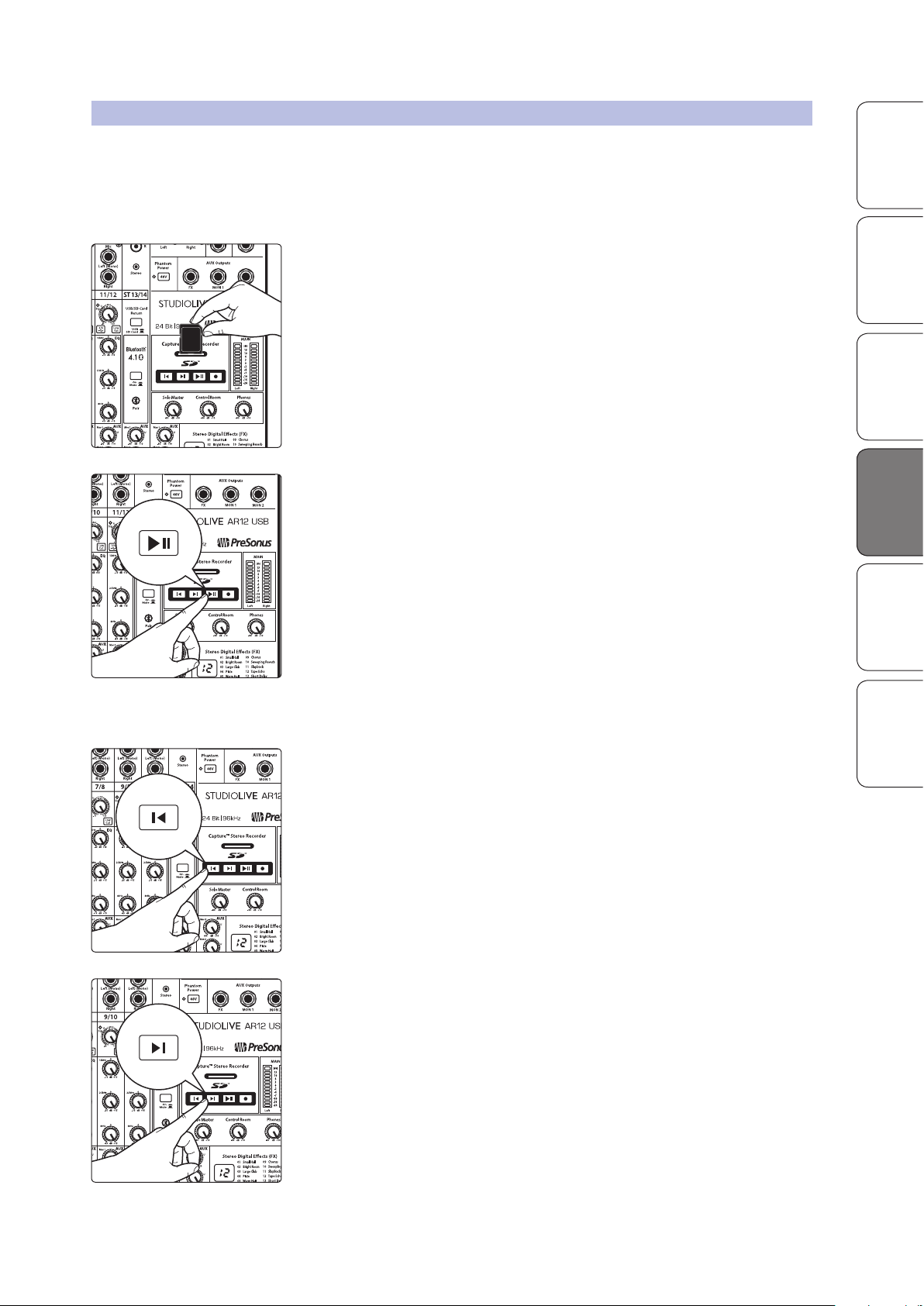
4.2 SD Playback
SD Card
StudioLive™ AR Series Owner’s Manual
Playing files from the SD card is a great way to listen to a performance right
away, and it can be useful during a performance. SD cards can be preloaded with
backing tracks for performance or rehearsal. Or load an SD card with your favorite
break music and never be caught without the right adapter or cable again.
To play audio from your SD recorder:
1. Insert into your StudioLive AR mixer a FAT16-formatted SD card or FAT32formatted SDHC card that has been pre-loaded with WAV or MP3 files or
that you have recorded to using your StudioLive AR mixer.
2. Press the Play/Pause button. The current stereo audio file will begin to play
at the last position. Playback will continue through all files, in alphanumeric
order, until the end of the last file has been reached; then playback will stop
automatically.
OverviewSD Recording
Getting StartedResources SD Recording
HookupTroubleshooting
and Playback
and Playback
3. Press the Play/Pause button again to pause
playback at the current file position.
4. Press the Return to Zero button to restart the current audio file. Press again
to move to the beginning of the previous file.
5. Press the Go to End button to advance playback to the end of the current
audio file. Press again to move to the end of the next file.
and Warranty
19
Page 22
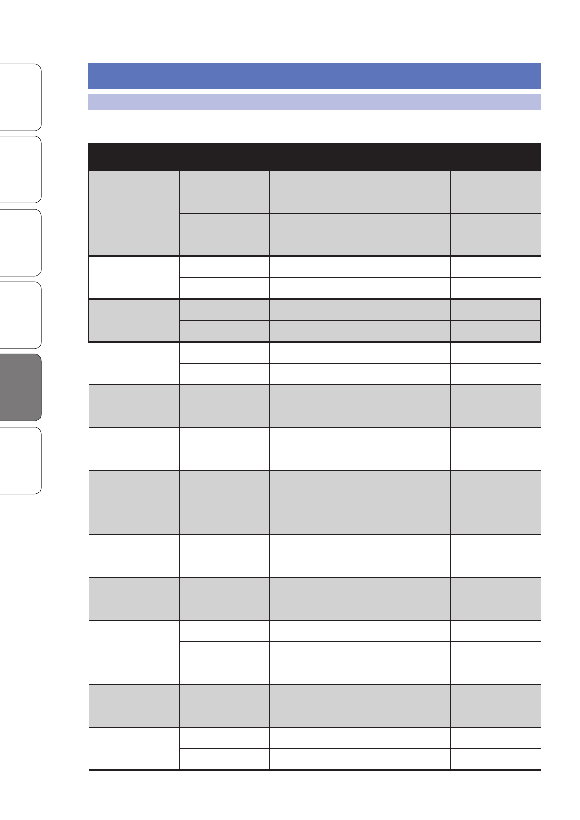
5.1 EQ Frequency Guides
Overview SD Recording
Getting Started Resources
Hookup Troubleshooting
and Playback
5 Resources
5.1 EQ Frequency Guides
Table 1
Instrument What to Cut Why to Cut What to Boost Why to Boost
Human Voice
Piano
Electric Guitar
Acoustic Guitar
7 kHz Sibilance 8 kHz Big sound
2 kHz Shrill 3 kHz and above Clarity
1 kHz Nasal 200-400 Hz Body
80 Hz and below Popping P’s
1-2 kHz Tinny 5 kHz More presence
300 Hz Boomy 100 Hz Bottom end
1-2 kHz Shrill 3 kHz Clarity
80 Hz and below Muddy 125 Hz Bottom end
2-3 kHz Tinny 5 kHz and above Sparkle
Resources
Electric Bass
and Warranty
String Bass
Snare Drum
Kick Drum
Toms
Cymbals
200 Hz Boomy 125 Hz Full
1 kHz Thin 600 Hz Growl
125 Hz Boomy 80 Hz and below Bottom end
600 Hz Hollow 2-5 kHz Sharp attack
200 Hz Boomy 125 Hz and below Bottom end
1 kHz Annoying 2 kHz Crisp
150-200 Hz Full
80 Hz Deep
400 Hz Muddy 2-5 kHz Sharp attack
80 Hz and below Boomy 60-125 Hz Bottom end
300 Hz Boomy 2-5 kHz Sharp attack
80-200 Hz Bottom end
1 kHz Annoying 7-8 kHz Sizzle
8-12 kHz Brilliance
Horns
String section
15 kHz Air
1 kHz Honky 8-12 kHz Big sound
120 Hz and below Muddy 2 kHz Clarity
3 kHz Shrill 2 kHz Clarity
120 Hz and below Muddy 400-600 Hz Lush and full
20
Page 23
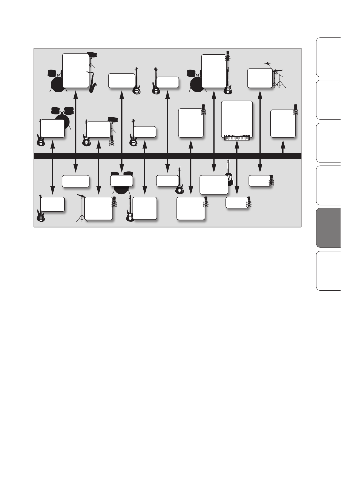
Table 2
•
bass “pluck”
•
acoustic/electric
guitar attack
•
lower piano register
attack
•
vocal clarity
•
decrease muddiness in
vocals and mid-range
instruments
•
decrease long bass
overtones in cymbals
•
enhance background
vocal breathiness
•
disguise vocals and
guitars that are slightly
out of tune
•
adds distance to
background
instruments
•
softens a “thin” guitar
•
breathier vocals
•
brighten cymbals,
string instruments,
flutes
•
more realistic
samples and synths
•
brighten vocals,
acoustic guitar,
piano
•
harder cymbals
•
vocal presence
•
kick & tom attack
•
more finger sound
on bass
•
piano and acoustic
guitar attack
•
brighter rock guitar
•
kick & tom attack
•
percussion attack
•
reduce vocal dullness
•
more finger sound on bass
•
sharpness to:
synths, rock guitars,
acoustic guitars, piano
•
bass line clarity
and punch
•
decrease kick and
tom dullness
•
decrease dullness
in guitars
•
vocals: reduce
“s” sound
•
vocals: reduce
“s” sound
•
bass line clarity
and punch
•
bass line clarity
(especially for softer
playback levels)
•
vocal fullness
•
hard hitting snare
and guitar
•
fullness to low
frequency
instruments
(kick, tom, bass)
•
decrease bass
“boom” to increase
clarity in the mix
•
decrease guitar
thinness
•
lessen overly
bright guitar
overtones
•
increase guitar clarity
•
lessen guitar “boom”
•
harder bass to low
frequency
instruments (kick,
tom, bass)
•
guitar and snare
fullness
•
piano and horns
warmth
50 Hz 100 Hz 200 Hz 400 Hz 800 Hz 1.5 kHz
BOOST
CUT
3 kHz 5 kHz 7 kHz 10 kHz 15 kHz
StudioLive™ AR Series Owner’s Manual
OverviewSD Recording
Getting StartedResourcesResources
HookupTroubleshooting
and Playback
and Warranty
21
Page 24
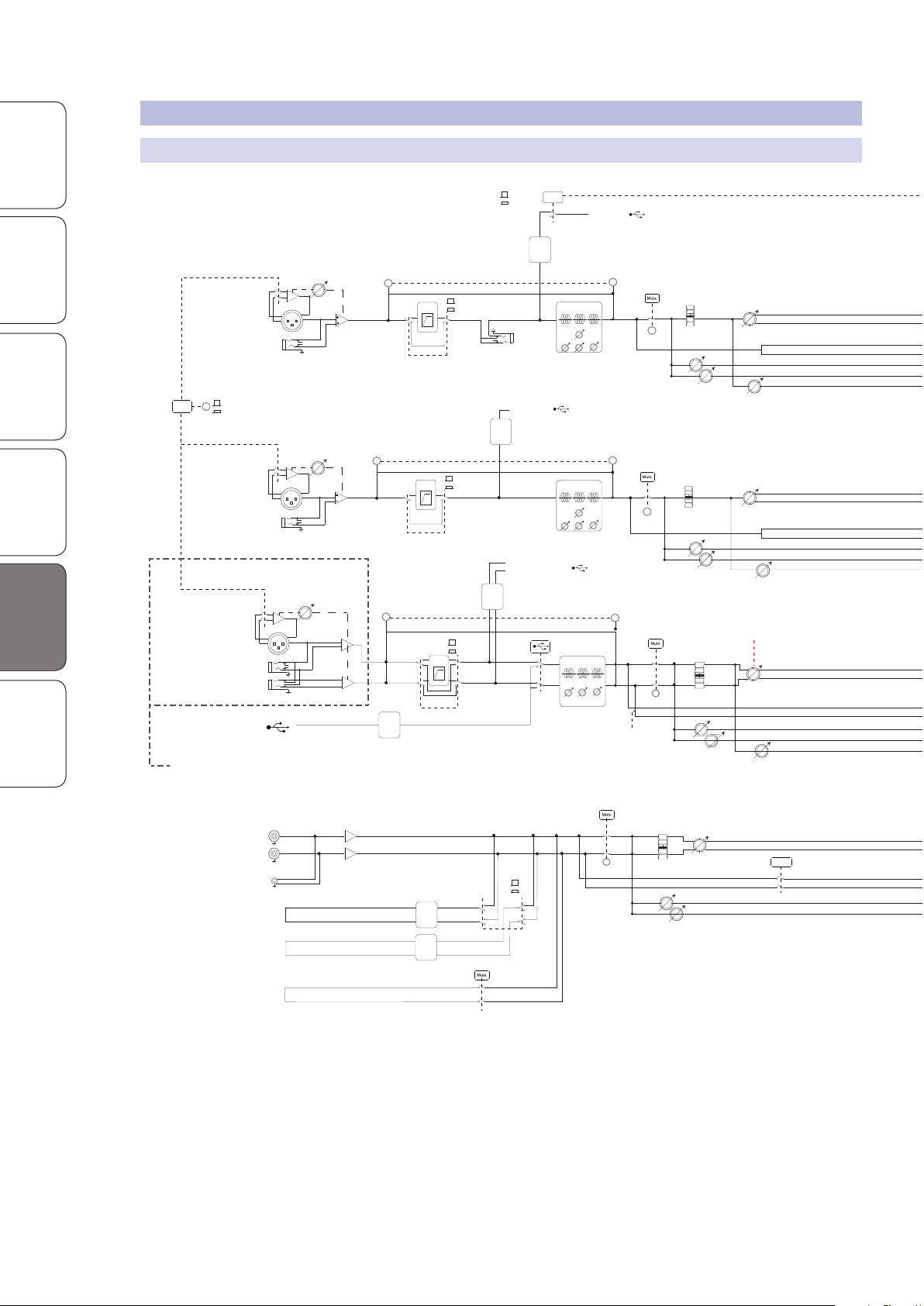
5.2 Block Diagrams
Main Mix L
Main Mix R
Solo Bus L
Mic Input
Line/Instrument Input
Input Channels 1&2
Channel Insert
USB Send 1&2
PFL
Pan
Main Mix L
Main Mix R
Gain
Instrument U +50 dB
Mic Pre
+
-
48V
Line -20 +30 dB
Mic U +50 dB
Level
Mon 1
Mon 2
FX
-120 - +10 dB
RCA Left
RCA RIGHT
Left (Mono)
Right
Equalizer
80 Hz 140 - 3500 Hz 12 kHz
-15 to +15 dB -15 to +15 dB -15 to +15 dB
Main Mix L
Main Mix R
Solo Bus L
Mic Input
Line Input
Mono Input Channels
USB Send 3-8
PFL
Pan
Main Mix L
Main Mix R
Gain
Mic Pre
+
-
Line -20 +30 dB
Mic U +50 dB
Level
-120 - +10 dB
Mon 1
Mon 2
FX
PFL
Solo
USB Return 3/4
PFL
Pan
Main Mix L
Main Mix R
Level
-120 - +10 dB
Mon 1
Mon 2
FX
PFL
Stereo Input Channels
(identical except
for USB Return on
last channel)
1/2
Main L/R USB SEND
STEREO 1/8”
PFL
BALANCE
Main Mix L
Main Mix R
Level
-120 - +10 dB
Mon 1
Mon 2
PFL
USB Return 1&2
SD Playback 1&2
ADC
ADC
DAC
DAC
DAC
Gain
Mic +5 +45
Mic Pre
Line -15 +25
Bluetooth
Level
Level
Level
Level
Main L/R
USB Send 9/10 - 15/16
ADC
ADC
(Channel 15/16 Only)
[if Mono: PFL send Splits to Left/Right. See ch 1-8]
PFL
PFL
USB / SD Toggle
USB 1&2
SD 1&2
[if Mono: Mains Splits to Left/Right. See ch 1-8]
If Left/Mono only is connected, signal is sent to both Left/Right on Main Bus and Solo Bus
If Right only is connected, signal is sent to the Right side only on the Main Bus or Solo Bus
Low Cut
On/Off
Low Cut In
Low Cut Out
Main L/R Send
Channel 1/2 Send
Signal
(green)
Equalizer
80 Hz 2.5 kHz 12 kHz
-15 to +15 dB -15 to +15 dB -15 to +15 dB
Equalizer
80 Hz 140 - 3500 Hz 12 kHz
-15 to +15 dB -15 to +15 dB -15 to +15 dB
48V On
48V Off
NOTE: All switches are shown in the default (up) position
Clip
(red)
Low Cut
On/Off
Low Cut In
Low Cut Out
Signal
(green)
Clip
(red)
Signal
(green)
Clip
(red)
Low Cut
On/Off
Low Cut In
Low Cut Out
Send Level
Send Level
Send Level
Send Level
Send Level
Send Level
Send Level
Super Channel
Overview SD Recording
5.2.1 StudioLive AR12 USB and AR16 USB Block Diagram
Getting Started Resources
5.2 Block Diagrams
Hookup Troubleshooting
and Playback
Resources
and Warranty
22
Page 25
Main Mix L
Main Mix R
Solo Bus L
Solo Bus R
Mon 1
Mon 2
FX
PFL
Main Mix L
Main Mix R
Main Output
Left
Right
+
-
+
-
+
-
+
-
BALANCE LINE DRIVERS
Solo Bus L
Solo Bus R
Cue Level
(PFL/AFL Master)
-120 - +10 dB
Master Bus USB Send 17/18
Main Meters
+
-
+
-
Mon 1
Mon 2
Mon Out 1
Mon Out 2
Main Mix L
Main Mix R
Solo Bus L
Solo Bus R
Mon 1
Mon2
FX
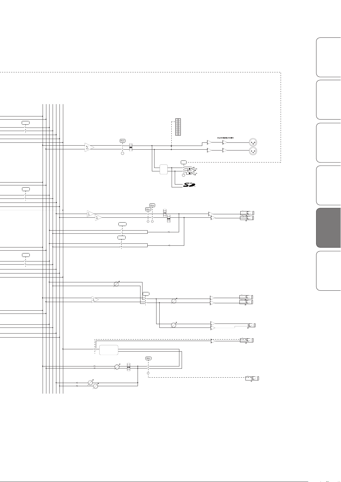
StudioLive™ AR12 USB & AR16 USB
BLOCK DIAGRAM
Rev Number 12/4/2015
PFL
Main Mix L
Main Mix R
PFL
Main Mix L
Main Mix R
Master Bus USB Send 1/2
1/2
USB Send
Mon 1
Mon 2
Main Left
Main Right
AFL
AFL
Control Room Bus L
Control Room Bus R
Monitor Level
-120 - +10 dB
PFL/AFL
Global
(any solo)
+
-
+
-
Control Room L
Control Room R
Control Room Out L
Control Room Out R
Phones Output
+
-
+
-
Phones Level
-120 - +10 dB
ADC
+
-
FX Out
FX Out
FX Bus Send
FX Engine
BALANCE
FX Bus Return L
FX Bus Return R
Footswitch
(FX Mute)
Send Level
Level
Level
Level
Master Bus Send to SD Recorder
Mon1
Mon 2
StudioLive™ AR Series Owner’s Manual
OverviewSD Recording
Getting StartedResourcesResources
HookupTroubleshooting
and Playback
and Warranty
23
Page 26
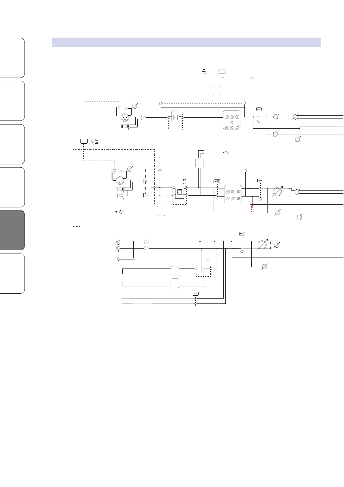
5.2 Block Diagrams
Mic Input
Line/Instrument Input
Input Channels 1&2
USB Send 1&2
PFL
Pan
Main Mix L
Main Mix R
Gain
Mic U + 50 dB
Instrument U +50 dB
Mic Pre
+
-
48V
Line -20 +30 dB
Level
Mon
FX
-120 - +10 dB
RCA Left
RCA RIGHT
Left (Mono)
Right
Equalizer
80 Hz 140 - 3500 Hz 12 kHz
-15 to +15 dB -15 to +15 dB -15 to +15 dB
Solo
USB Return 3/4
PFL
Pan
Main Mix L
Main Mix R
Level
-120 - +10 dB
Mon
FX
PFL
Stereo Input Channels
3/4-5/6
(identical except
for USB Return on
5/6)
1/2
Main L/R USB SEND
STEREO 1/8”
PFL
BALANCE
Main Mix L
Main Mix R
Level
-120 - +10 dB
Mon
PFL
USB Return 1&2
SD Playback 1&2
ADC
DAC
DAC
DAC
Gain
Mic +5 +45
Mic Pre
Line -15 +25
Bluetooth
Main L/R
USB Send 3/4-5/6
ADC
ADC
(Channel 5/6 Only)
[if Mono: PFL send Splits to Left/Right. See ch 1-2]
PFL
PFL
USB / SD Toggle
USB 1&2
SD 1&2
[if Mono: Mains Splits to Left/Right. See ch 1-2]
If Left/Mono only is connected, signal is sent to both Left/Right on Main Bus and Solo Bus
If Right only is connected, signal is sent to the Right side only on the Main Bus or Solo Bus
Low Cut
On/Off
Low Cut In
Low Cut Out
Main L/R Send
Channel 1/2 Send
Signal
(green)
Equalizer
80 Hz 2.5 kHz 12 kHz
-15 to +15 dB -15 to +15 dB -15 to +15 dB
48V On
48V Off
NOTE: All switches are shown in the default (up) position
Clip
(red)
Signal
(green)
Clip
(red)
Low Cut
On/Off
Low Cut In
Low Cut Out
Send Level
Send Level
Send Level
Send Level
Send Level
LEVEL
LEVEL
LEVEL
Super Channel
Overview SD Recording
Getting Started Resources
Hookup Troubleshooting
and Playback
Resources
and Warranty
5.2.2 StudioLive AR8 USB Block Diagram
24
Page 27
Main Mix L
Main Mix R
Solo Bus L
Solo Bus R
Mon
FX
PFL
Main Mix L
Main Mix R
Main Output
Left
Right
+
-
+
-
+
-
+
-
BALANCE LINE DRIVERS
Solo Bus L
Solo Bus R
Cue Level
(PFL/AFL Master)
-120 - +10 dB
Master Bus USB Send 7/8
Main Meters
+
-
Mon
Mon Out
Main Mix L
Main Mix R
Solo Bus L
Solo Bus R
Mon
FX
PFL
Main Mix L
Main Mix R
PFL
Main Mix L
Main Mix R
Master Bus USB Send 1/2
1/2
USB Send
Mon
Main Left
Main Right
AFL
Control Room Bus L
Control Room Bus R
Monitor Level
-120 - +10 dB
PFL/AFL
Global
(any solo)
+
-
+
-
Control Room L
Control Room R
Control Room Out L
Control Room Out R
Phones Output
+
-
+
-
Phones Level
-120 - +10 dB
ADC
+
-
FX Out
FX Out
FX Bus Send
FX Engine
BALANCE
FX Bus Return L
FX Bus Return R
Footswitch
(FX Mute)
Send Level
Master Bus Send to SD Recorder
Mon
LEVEL
LEVEL
LEVEL
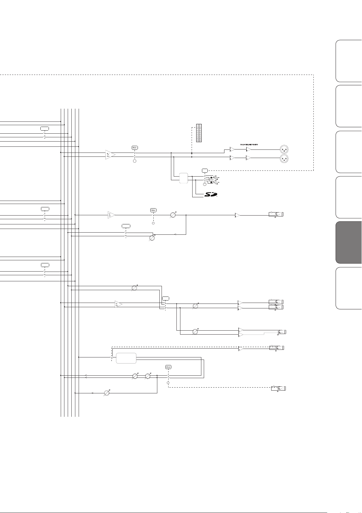
StudioLive™ AR8 USB
BLOCK DIAGRAM
Rev Number 12/4/2015
StudioLive™ AR Series Owner’s Manual
OverviewSD Recording
Getting StartedResourcesResources
HookupTroubleshooting
and Playback
and Warranty
25
Page 28
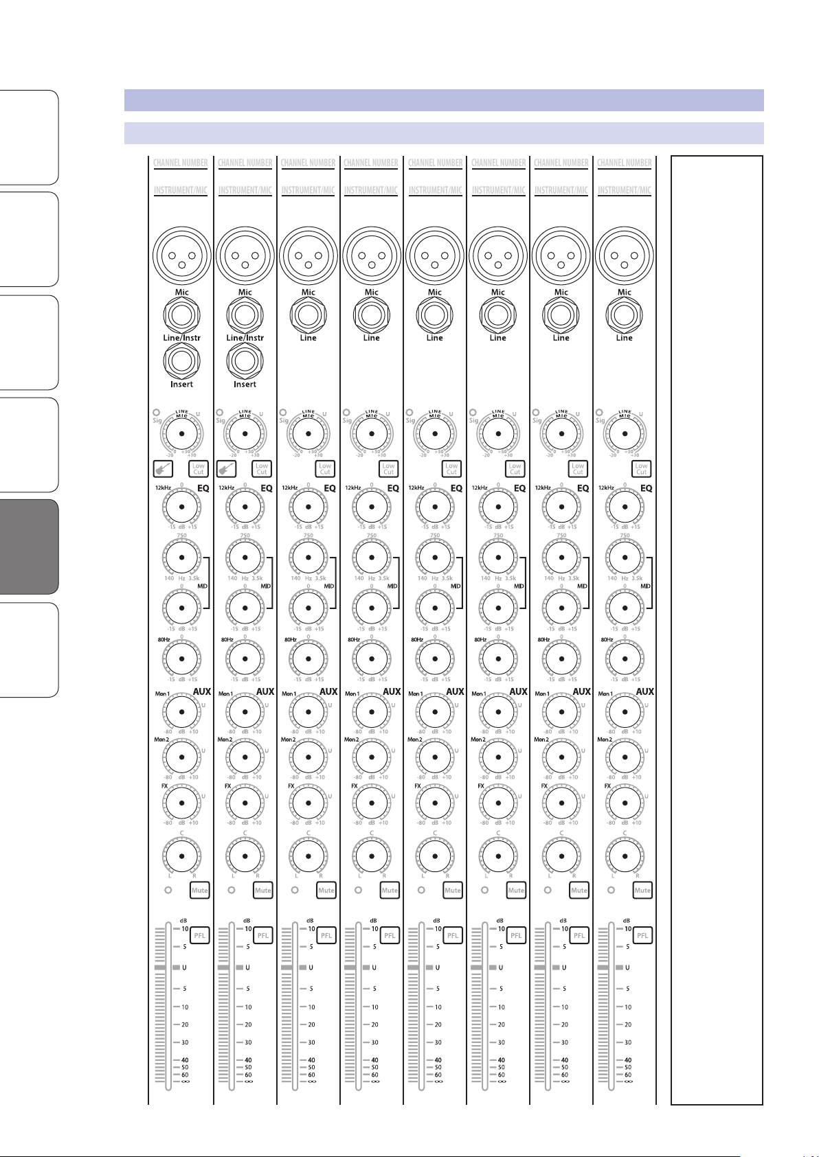
5.3 Recall Sheets
Stereo
Mono
INSTRUMENT/MIC
NOTE
NOTE
CHANNEL NUMBER
INSTRUMENT/MIC
CHANNEL NUMBER
ADDITIONAL NOTES
INSTRUMENT/MIC
CHANNEL NUMBER
INSTRUMENT/MIC
CHANNEL NUMBER
INSTRUMENT/MIC
CHANNEL NUMBER
INSTRUMENT/MIC
CHANNEL NUMBER
INSTRUMENT/MIC
CHANNEL NUMBER
INSTRUMENT/MIC
CHANNEL NUMBER
INSTRUMENT/MIC
CHANNEL NUMBER
INSTRUMENT/MIC
CHANNEL NUMBER
INSTRUMENT/MIC
CHANNEL NUMBER
INSTRUMENT/MIC
CHANNEL NUMBER
SOURCE
CARD NAME
NOTE
NOTE
NOTE
NOTE
NOTE
NOTE
Overview SD Recording
Getting Started Resources
Hookup Troubleshooting
and Playback
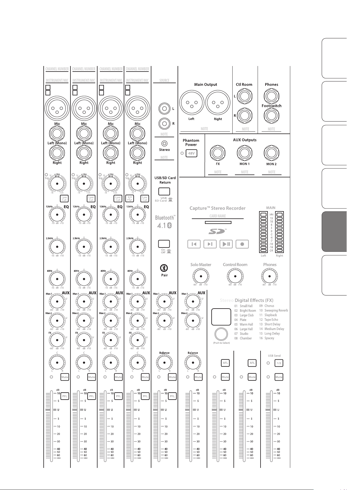
5.3 Recall Sheets
5.3.1 AR16 USB and AR12 USB Recall Sheet
Resources
and Warranty
26
Page 29
StudioLive™ AR Series Owner’s Manual
Stereo
Mono
Stereo
Mono
Stereo
Mono
Stereo
Mono
INSTRUMENT/MIC
NOTE
NOTE
CHANNEL NUMBER
INSTRUMENT/MIC
CHANNEL NUMBER
INSTRUMENT/MIC
CHANNEL NUMBER
INSTRUMENT/MIC
CHANNEL NUMBER
SOURCE
CARD NAME
NOTE
NOTE
NOTE
NOTE
NOTE
NOTE
ENTER
PRESET NUMBER
OverviewSD Recording
Getting StartedResourcesResources
HookupTroubleshooting
and Playback
and Warranty
27
Page 30
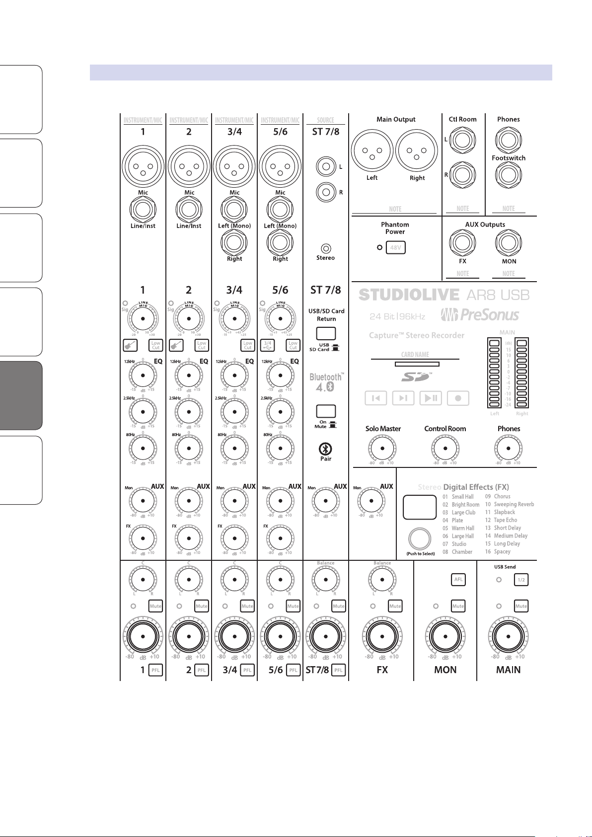
5.3 Recall Sheets
CARD NAME
INSTRUMENT/MIC
SOURCE
INSTRUMENT/MIC
INSTRUMENT/MIC
INSTRUMENT/MIC
NOTE
NOTE
NOTE
NOTE
NOTE
ENTER
PRESET NUMBER
Overview SD Recording
Getting Started Resources
Hookup Troubleshooting
and Playback
5.3.2 AR8 USB Recall Sheet
Resources
and Warranty
28
Page 31
StudioLive™ AR Series Owner’s Manual
5.4 Technical Specifications
Microphone Preamp
Type XLR Female, Class A
Maximum Input level (unity gain) +18 dBu (Mono Channels), -5 dBu (Stereo Channels) +/- 1.0 dB
Gain Control Range Mono Channels: 50 dB, ±1 dB (Unity to +50 dB),
Stereo Channels: 40 dB +/- 1 dB (+4 to +45 dB)
Frequency Response to Analog Outputs 20 Hz to 20 kHz, +0.5/-1.5 dB
Frequency Response to USB (Direct) 20 Hz to 40 kHz, +0.5/- 1.5 dB
S/N Ratio to Outputs (+4 dBu) 94 dB
THD+N (min. gain, A-wtd) < 0.01%
Input Impedance 1 kΩ
EIN (+55 dB gain, 150Ω input, 20 Hz-22 kHz, A-wtd) < 128 dBu
Common Mode Rejection Ratio (1 kHz, +55 dB gain) 65 dB
Phantom Power +48 V, ±3V, Global
*Note: All channel inputs sum through mic preamp.
Instrument Inputs
Type ¼” TS Female, Unbalanced, Hi-Z
Maximum Input Level (min. gain, 1 [email protected]% THD+N) +18 dBu ±1.0 dB
Gain Control Range 50 dB, ±1 dB (Unity to +50 dB)
Frequency Response to Analog Outputs 20 Hz to 20 kHz, +0.5/-1.5 dB
Frequency Response to USB (Direct) 20 Hz to 40 kHz, +0.5/-1.5 dB
Dynamic Range (min. gain, A-wtd) > 105 dB
Dynamic Range (mid. Gain, unwtd) > 100 dB
THD+N (1 kHz, -1 dBFS, A-wtd) < 0.01%
THD+N (1 kHz, -1 dBFS, unwtd) < 0.01%
Input Impedance > 1 MΩ
*Note: All Channel Inputs sum through Mic preamp.
OverviewSD Recording
Getting StartedResourcesResources
HookupTroubleshooting
and Playback
and Warranty
Line Inputs
Type ¼” TRS Female, Balanced
Maximum Input Level (min. gain, 1 [email protected]% THD+N) +22 dBu, ±1.0 dB
Gain Control Range Mono Channels: 50 dB, +/- 1 dB (-30 to +20 dB),
Stereo Channels: 40 dB, +/- 1 dB (-15 to +25 dB)
Frequency Response to Analog Outputs 20 Hz to 20 kHz, +0.5/-1.5 dB
Frequency Response to USB (Direct) 10 Hz to 40 kHz, +0.5/-1.5 dB
S/N Ratio to Analog Outputs (+4 dBu) 94 dB
THD+N (1 kHz, -1 dBFS, A-wtd) < 0.01%
Input Impedance (Balanced) 10 kΩ
*Note: All Channel Inputs sum through Mic preamp.
29
Page 32
Overview SD Recording
Getting Started Resources
Hookup Troubleshooting
and Playback
5.4 Technical Specifications
Main, Control Room, Monitor, and FX Outputs
Type (Main Outputs) XLR Male, Impedance Balanced
Type (Control Room, Monitor, FX Outputs) ¼” TRS Female, Balanced
Rated Output Level (Main Outputs) +24 dBu, ±1.0 dB
Rated Output Level (Control Room, Monitor, FX Outputs) +18 dBu
Frequency Response 20 Hz to 20 kHz, +0.5/-1.5 dB
Dynamic Range (A-wtd) > 108 dB
THD+N (Bandwidth 20~20 kHz, -1 dBFS, unwtd) < 0.01%
Output Impedance 100 Ω
Headphone Output
Type ¼” TRS Female, Stereo, Unbalanced
Maximum Output Level 150 mW/channel @ 60Ω
Frequency Response 20 Hz to 20 kHz, +0.5/-1.5 dB
Dynamic Range (a-wtd) > 103 dB
THD+N (Bandwidth 20~20 kHz, -1 dBFS, unwtd) < 0.01%
System Crosstalk
Input to Output (Ref = +4 dBu, 20 Hz to 20 kHz, unwtd) -85 dBu
Adjacent Channels (Ref = +4 dBu, 20 Hz to 20 kHz, unwtd) -80 dBu
Resources
Signal Level LED
Signal -50 dBFS (pre-EQ)
Clip -3.0 dB before clip (pre- or post-EQ)
Channel EQ
and Warranty
Low Cut 100 Hz, -18 dB/octave
High Shelving ±15 dB @ 12 kHz
Mid Peaking (Mono Channels: AR16 USB, AR12 USB) ±15 dB @ 140 Hz to 3.5 kHz (variable)
Mid Peaking (Stereo Channels: AR16 USB, AR12 USB, All: AR8 USB) ±15 dB @ 2.5 kHz
Mid-Band Q Fixed, 0.55
Low Shelving ±15 dB @ 80 Hz
Digital Audio
Host Interface USB 2.0
ADC Dynamic Range (Component) 114 dB
ADC Dynamic Range (Measured: A-wtd, 48 kHz) 105 dB
DAC Dynamic Range (Component) 114 dB
DAC Dynamic Range (Measured: A-wtd, 48 kHz) 105 dB
Bit Depth 24-bit
Internally Supported Sample Rates 44.1, 48, 88.2, 96 kHz
Jitter <80 ps RMS (20 Hz – 20 kHz)
Jitter Attenuation >60 dB (1 ns in => 1 ps out)
30
Page 33
StudioLive™ AR Series Owner’s Manual
SD Recorder
Supported Media Format FAT16-formatted SD Card, FAT32-formatted SDHC Card
Media Storage Capacity SD Card: 2 GB, SDHC Card: 32 GB
Recording File Format Stereo WAV
Playback File Formats Stereo WAV, MP3
Sampling Rate (WAV) 44.1 kHz
Bit Depth (Recorded WAV) 24-bit
OverviewSD Recording
Power
Connector IEC
Input Voltage Range 90 to 240 VAC
Physical AR16 USB AR12 USB AR8 USB
Length 15.6” (397 mm) 15.6” (397 mm) 12.3” (313 mm)
Width (chassis only) 18.9” (480 mm) 15” (381 mm) 11” (284 mm)
Maximum Height 3.5” (89 mm) 3.5” (89 mm) 3.5” (89mm)
Weight 14.1 lbs (6.4 kg) 11.9 lbs (5.4 kg) 7.1 lbs (3.2 kg)
Global Warming
Recommended Ambient Operating Temperature 0˚ to 40˚ Celsius / 32˚ to 104˚ Fahrenheit
Getting StartedResourcesResources
HookupTroubleshooting
and Playback
and Warranty
31
Page 34

6.1 Troubleshooting
Overview SD Recording
Getting Started Resources
Hookup Troubleshooting
and Playback
6 Troubleshooting and Warranty
6.1 Troubleshooting
Please check the PreSonus Web site (www.presonus.com) regularly
for software information and updates, firmware updates, and support
documentation, including frequently asked questions.
Online technical support is available from within your My PreSonus account.
PreSonus telephone technical support is available to customers in the USA on
Monday through Friday from 9 a.m. to 5 p.m. Central Time by calling 1-225216-7887. Customers outside of the USA should contact their national or
regional distributor for telephone technical support. A list of international
distributors is provided at www.presonus.com/buy/international_distributors.
No Output on a Channel
Check the signal-present LED and verify that there is signal on that channel. If no
signal is present, check the cable and the input source. Verify that the trim control
is set at an appropriate level. Make sure the channel is not muted. Make sure that if
your device requires phantom power, phantom power is engaged for the channel.
No Output on the Solo Bus While Monitoring
Verify that both the Cue volume and the headphone, or monitor,
volume is at a reasonable level for comfortable listening and that
the PFL button is engaged on the desired channels..
Can’t Hear Main Mix in Headphones
Verify the headphone output control is at a sufficient level.
Make sure that no PFL or AFL buttons are engaged.
Troubleshooting
and Warranty
and Warranty
Control Room Level Not Affecting Volume
Verify that your monitors are connected to the Control Room
outputs of your StudioLive AR, not the Main outputs.
Main Fader Doesn’t Control Mix Level
Verify that your monitors are connected to the Main
outputs, not the Control Room outputs.
Microphone Preamp 1 or 2 Doesn’t Pass Audio
First, verify that the Instrument input button is not engaged. This disables
the microphone preamp. Next, verify that your microphone cable is
operational and that the trim control is set at an appropriate level.
32
Page 35
6.2 Warranty Information
PreSonus’ warranty obligations for this hardware product
are limited to the terms set forth below:
6.2.1 How Consumer Law Relates To This Warranty
THIS WARRANTY GIVES YOU SPECIFIC LEGAL RIGHTS, AND YOU MAY HAVE OTHER
RIGHTS THAT VARY FROM STATE TO STATE (OR BY COUNTRY OR PROVINCE). OTHER
THAN AS PERMITTED BY LAW, PRESONUS DOES NOT EXCLUDE, LIMIT OR SUSPEND
OTHER RIGHTS YOU MAY HAVE, INCLUDING THOSE THAT MAY ARISE FROM THE
NONCONFORMITY OF A SALES CONTRACT. FOR A FULL UNDERSTANDING OF YOUR
RIGHTS YOU SHOULD CONSULT THE LAWS OF YOUR COUNTRY PROVINCE OR STATE.
PreSonus Products And EU Statutory Warranty
When you purchase PreSonus products, European Union consumer
law provides statutory warranty rights in addition to the coverage
you receive from the PreSonus limited warranty. A summary of the EU
Statutory Warranty and the PreSonus Limited Warranty is below:
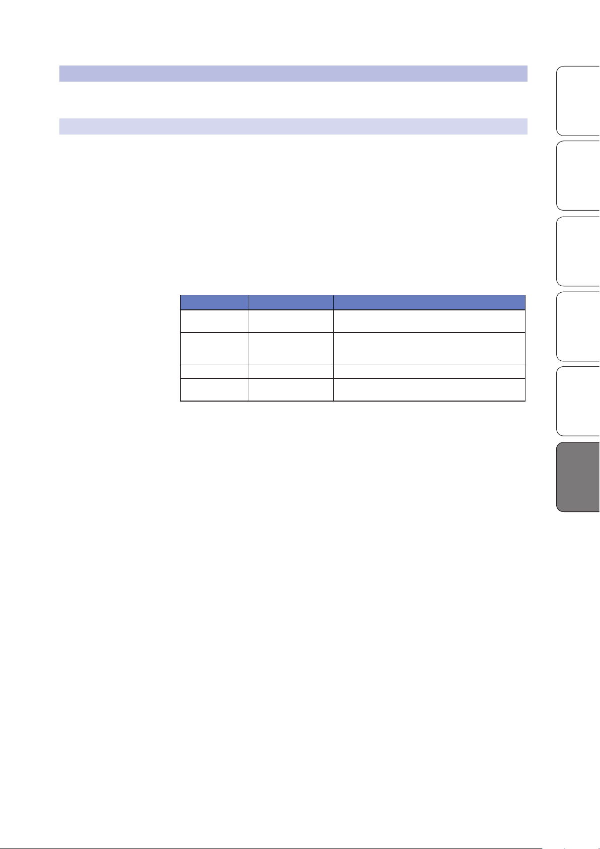
EU Consumer Law PreSonus Limited Warranty
Repair or Replacement
Coverage For
Warranty Period
Cost of Coverage Provided at no additional cost Included at no additional cost
Who to contact to make
a claim
Defects present when customer
takes delivery
2 years (minimum) from
original date of purchase (unless
superseded by PreSonus)
The seller PreSonus technical support for your region
StudioLive™ AR Series Owner’s Manual
Defects arising after customer takes delivery
1 year from original date of purchase (unless superseded by PreSonus)
OverviewSD Recording
Getting StartedResourcesTroubleshooting
HookupTroubleshooting
and Playback
What This Warranty Covers
PreSonus Audio Electronics, Inc., (“PreSonus”) warrants defects in material and
workmanship in PreSonus-branded products under normal use. This Limited
Warranty applies only to hardware products manufactured by or for PreSonus that
can be identified by the PreSonus trademark, trade name, or logo affixed to them.
Exclusions and Limitations
This warranty does not cover the following:
1. Damage caused by accident, abuse, improper installation, failure to
2. Damage from improper grounding, faulty wiring (AC and signal),
3. Damage to drivers or diaphragm assemblies found to have burnt voice
4. Damage occurring during shipment or improper handling.
5. Damage caused by repair or service performed by
6. Products on which the serial number has been altered, defaced, or removed.
7. Products purchased from an unauthorized PreSonus dealer (products
follow instructions in the applicable owner’s manual or improper
operation, rental, product modification, alteration, or neglect.
faulty equipment, or connection to a voltage range outside
published specifications (see applicable owner’s manual).
coils from over/under driving or signal surge from another device.
persons not authorized by PreSonus.
that have transferable warranties are excluded from this provision
provided the customer and the product are registered with PreSonus).
and Warranty
and Warranty
33
Page 36

Overview SD Recording
Getting Started Resources
Hookup Troubleshooting
and Playback
Troubleshooting
and Warranty
and Warranty
6.2 Warranty Information
Who This Warranty Protects
This Warranty protects only the original retail purchaser of the product
(products that have transferable warranties are excluded from this provision
provided the customer and the product are registered with PreSonus)
How Long This Warranty Lasts
A 1-Year Limited Warranty begins on the original date
of purchase from the retail purchaser.
What PreSonus Will Do
PreSonus will repair or replace, at our sole and absolute option, products
covered by this warranty at no charge for labor or materials. If the product
must be shipped to PreSonus for warranty service, the customer must pay the
initial shipping charges. PreSonus will pay the return shipping charges.
How to Get Warranty Service (USA)
1. You must have an active user account with PreSonus and your hardware
must be on file with your account. If you do not have an account, please
go to https://my.presonus.com and complete the registration process.
2. Contact our Technical Support Department at (225) 216-7887 or log a support
ticket at: http://support.presonus.com. TO AVOID THE POSSIBILITY OF
SENDING IN A PRODUCT THAT DOES NOT HAVE A PROBLEM, ALL SERVICE
REQUESTS SHALL BE CONFIRMED BY OUR TECH SUPPORT DEPARTMENT.
3. The return authorization number, as well as shipping instructions, shall
be provided after your service request is reviewed and confirmed.
4. The product should be returned for service in the original product
packaging. Products may be shipped in a manufactured “flight” or “road”
style cases but PreSonus will NOT cover any shipping damage to these
cases. Products that are not shipped in the original product package or
a manufactured case may not receive a warranty repair, at PreSonus’ sole
discretion. Depending on the product model and the condition of your
original packaging, your product may not be returned to you in the original
packaging. The return shipping box may be a generic box that has been
fitted for that model tested if the original gift box is not available.
How to Get Warranty Service (outside of USA)
1. You must have an active user account with PreSonus and your hardware
must be on file with your account. If you do not have an account, please
go to: https://my.presonus.com and complete the registration process.
2. Contact the Technical Support/Service Department for your
region at www.presonus.com/buy/international_distributors
and follow procedures provided by your PreSonus contact.
34
Page 37

Limitation of Implied Warranties
ANY IMPLIED WARRANTIES, INCLUDING WARRANTIES OF
MERCHANTABILITY AND FITNESS FOR A PARTICULAR PURPOSE, ARE
LIMITED IN DURATION TO THE LENGTH OF THIS WARRANTY.
Some states, countries, or provinces do not allow limitations on how long
an implied warranty lasts, so the above limitation may not apply to you.
Exclusion of Damages
PRESONUS’S LIABILITY FOR ANY DEFECTIVE PRODUCT IS LIMITED TO THE
REPAIR OR REPLACEMENT OF THE PRODUCT, AT PRESONUS’S SOLE OPTION. IF
PRESONUS ELECTS TO REPLACE THE PRODUCT, THE REPLACEMENT MAY BE A
RECONDITIONED UNIT. IN NO EVENT WILL PRESONUS BE LIABLE FOR DAMAGES
BASED ON INCONVENIENCE, LOSS OF USE, LOST PROFITS, LOST SAVINGS, DAMAGE
TO ANY OTHER EQUIPMENT OR OTHER ITEMS AT THE SITE OF USE, AND, TO THE
EXTENT PERMITTED BY LAW, DAMAGES FOR PERSONAL INJURY, OR ANY OTHER
DAMAGES WHETHER INCIDENTAL, CONSEQUENTIAL OR OTHERWISE, EVEN IF
PRESONUS HAS BEEN ADVISED OF THE POSSIBILITY OF SUCH DAMAGES.
Some states, countries, or provinces do not allow limitations on how long
an implied warranty lasts, so the above limitation may not apply to you.
If you have any questions about this warranty or service received, please contact
PreSonus (USA) at +1-225-216-7887 or contact one of our authorized international
distributors at www.presonus.com/buy/international_distributors.
Product features, design, and specifications are subject to change without notice.
StudioLive™ AR Series Owner’s Manual
OverviewSD Recording
Getting StartedResourcesTroubleshooting
HookupTroubleshooting
and Playback
and Warranty
and Warranty
35
Page 38

Page 39

Dinner is Served
Added bonus: PreSonus’ previously Top Secret recipe for…
Chicken and Andouille Gumbo
Ingredients:
• 1 C All-Purpose flour
• ¾ C Vegetable Oil
• 1 large onion (diced)
• 1 small onion (quartered)
• 6 celery stalks (diced)
• 1 large green bell pepper (diced)
• 3 cloves garlic (2 minced, 1 whole)
• 1 lb link Andouille sausage
• 4 Chicken leg quarters
• 4 qt water
• 4 bay leaves
• 1 tsp thyme
• 1 tsp Old Bay seasoning
• 1-2 C frozen okra, sliced
• ¼ C fresh parsley, minced
• 6-8 eggs (optional)
Cooking Instructions:
1. In a large pot, combine whole chicken leg quarters, water, quartered onion, Old Bay, 2 bay leaves and 1 whole clove garlic.
Cover and bring to a low boil. Simmer stock until chicken is falling off the bone. Remove the chicken and set aside. Discard
the onion, bay leaves, and garlic, reserving the liquid.
2. In a heavy saucepan, heat 1 Tbsp of the oil on medium high heat and brown the andouille until it is cooked through. Set
aside sausage for later.
3. In the same saucepan, add and heat remaining oil. Slowly add flour 1-2 Tbsp at a time, stirring continuously. Continue
cooking and stirring the roux until it is a dark brown (it should look like melted dark chocolate). Be careful to not to get the
oil too hot or the flour will burn and you’ll have to start over.
4. Once roux has reached the correct color, add diced onion, celery, green pepper, and minced garlic. Cook until vegetables
are very tender. Do not cover.
5. Slowly add 1 quart of chicken broth and bring to a low boil, stirring constantly.
6. Transfer roux mixture to a soup pot and bring to low boil. Do not cover, the roux will settle on the bottom of the pot and burn.
7. Add remaining chicken broth, bay leaves, and thyme. Simmer for 30 minutes.
8. While gumbo is simmering, debone and shred chicken and slice the andouille.
9. Add chicken and andouille to gumbo and return to a simmer. Simmer for 30-45 minutes.
10. Stir in frozen okra and parsley and bring to a rolling boil.
11. Optional: Crack one egg into a teacup and quickly pour into the boiling gumbo. Repeat with the other eggs being careful
not to cluster them too closely. After all the eggs have risen back to the surface, reduce heat and simmer.
12. Correct seasoning with salt and pepper (red, white and/or black) if necessary.
13. Serve over rice with potato salad.
Serves 12
© 2016 PreSonus Audio Electronics, Inc. All Rights Reserved. AudioBox, CoActual, DigiMax, Eris, FireStudio, Nimbit, PreSonus, QMix, Riff to Release, Sceptre, StudioLive, Active
Integration, and XMAX are trademarks or registered trademarks of PreSonus Audio Electronics, Inc. Capture, Impact, Mixverb Presence, RedLightDist, SampleOne, Studio One, and
Tricomp are trademarks or registered trademarks of PreSonus Software Ltd. Mac and Mac OS are registered trademarks of Apple, Inc., in the U.S. and other countries. Windows is a
registered trademark of Microsoft, Inc., in the U.S. and other countries. The SD Logo is a trademark of SD-3C, LLC. Other product names mentioned herein may be trademarks of their
respective companies. All specifications subject to change without notice...except the recipe, which is a classic.
Page 40
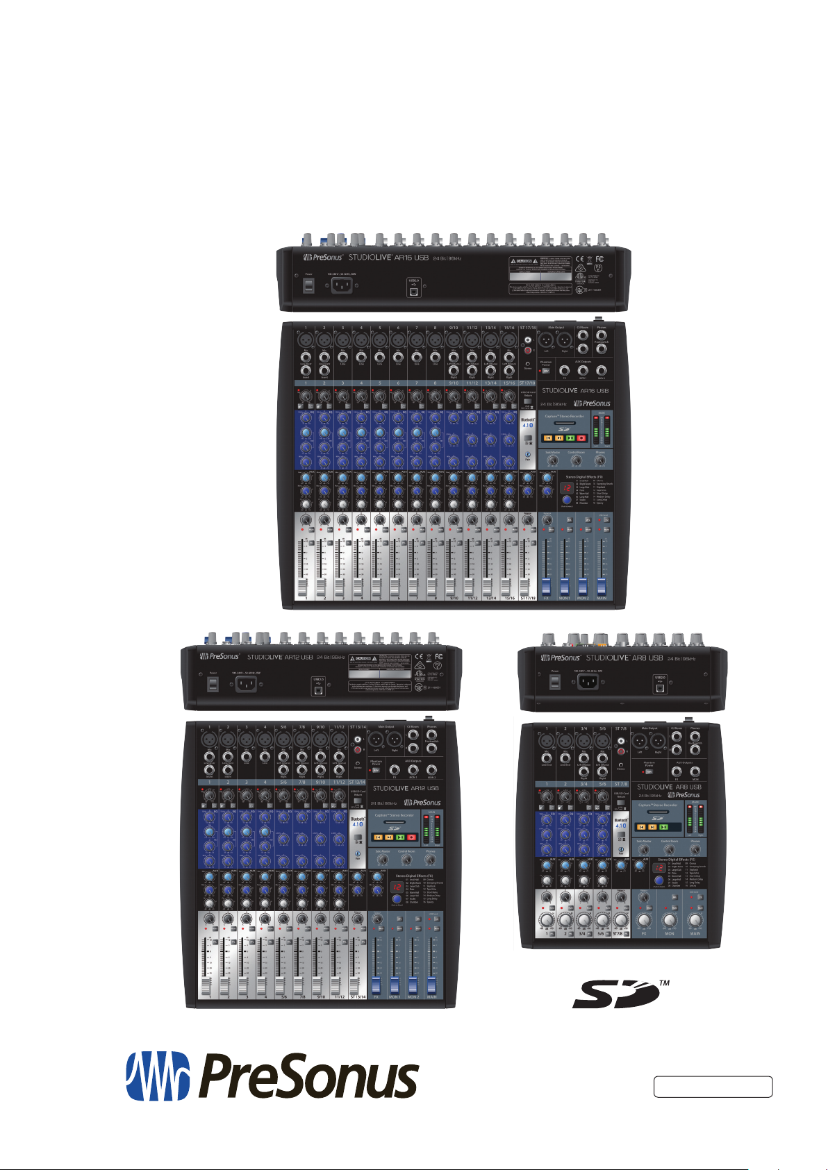
StudioLive™ AR-Series
Hybrid Digital/Analog Production Mixers
Owner’s Manual
18011 Grand Bay Ct. • Baton Rouge,
®
Louisiana 70809 USA• 1-225-216-7887
www.presonus.com
Part# 70-22000031-A
 Loading...