

Page 1
StudioLive™ Series III
AVB Networking Guide
www.presonus.com
®
English
Page 2

Table of Contents
1 Overview — 1
1.1 An Introduction to Audio Networking — 2
1.2 Distributed Audio — 2
1.3 Network Foundations — 3
1.4 Addressing — 3
2 AVB Networking — 4
2.1 System Overview — 4
2.2 What is AVB? — 5
2.3 How Does AVB Work? — 6
2.4 AVB Hardware Components — 6
2.5 Overcoming Latency — 7
2.6 Channels and Streams — 7
2.7 Clocking — 8
2.7.1 Wordclock — 8
2.7.2 Precision Time Protocol (PTP) — 9
2.7.3 Multiple Stream Reservation Protocol
(MSRP) — 9
2.7.4 Clocking a PreSonus AVB Network — 11
3 AVB Networking Basics — 13
3.1 Selecting the Right Switch — 13
3.1.1 PreSonus SW5E AVB Switch
with PoE — 13
3.2 Adding a Wireless Router — 15
3.3 Choosing the Right Cables — 16
3.3.1 Cat5e and Cat6 — 16
3.3.2 Shielded vs. Unshielded — 17
3.3.3 Solid-core vs. Stranded — 18
3.3.4 Plug Termination — 19
3.3.5 T568A or T568B — 19
3.3.6 Twisted Pair Tips — 19
3.4 Understanding Hops — 20
3.5 Network Topologies — 21
3.5.1 Point-to-Point (P2P) — 21
3.5.2 Daisy-Chain — 22
3.5.3 Star — 23
4 Configuring Your AVB
Network — 24
4.1 Using AVB with a StudioLive Series III Mixer and a
Mac — 24
4.1.1 What You Will Need — 24
4.1.2 Making the Connections — 24
4.1.3 Setting Up Your Mac — 25
4.2 NSB-series Stage Box with a StudioLive Series III
Console Mixer — 26
4.2.1 Step 1: Connect Your Stage Box
to Your Mixer — 26
4.2.2. Step 2: Routing Stage Box Inputs
to Mixer — 28
4.2.3 Step 3: Engage Network Sources — 28
4.3 NSB-series Stage Box UC Surface Setup — 29
4.3.1 Step 1: Connect Your Stage Box
to Your Mixer — 29
4.3.2 Step 2: Routing Stage Box Inputs
to Your Mixer — 30
4.3.3 Step 3: Engage Network Sources — 30
4.4 EarMix 16M with StudioLive
Console Mixers — 31
4.5 EarMix 16M Setup from UC Surface — 32
5 Large Network:
Real-world Example — 34
5.1 Example Network Overview — 34
5.2 Network Connections — 37
5.2.1 Connecting Your Mixers — 39
5.2.2 Connect Your NSB-series Stage Boxes
to Your Console Mixers — 41
Page 3

5.3 Analog Input Connections — 44
5.3.1 Routing AVB Sends
to Your Console Mixers — 46
5.3.2 Routing the NSB-series Inputs
to Your StudioLive 24R — 48
5.3.3 Routing Audio to the
Console Mixers — 49
5.4 Analog Output Connections — 51
5.4.1 Routing the Main Outputs — 51
5.4.2 Routing Monitor Mixes — 52
5.5 EarMix Setup — 53
5.5.1 Routing AVB Streams to Your
EarMix 16M — 53
5.5.2 Routing StudioLive 24R Sources
to AVB Sends — 54
Page 4
1
1 Overview
StudioLive™ Series III
AVB Networking Guide
1 Overview
Most people who have used a digital mixer in the last ten years are familiar with
incorporating networking technology into their audio application. Remote control
over wireless LAN networks, proprietary audio-over-Ethernet protocols, and
extensible audio networking platforms have all become relatively commonplace.
As networking speed and reliability have increased and the underlying technology
has become more affordable, transporting audio over an Ethernet cable can now
offer dramatic savings of both time and money, making it more attractive than ever.
While there are several protocols currently in use for audio networking, AVB
has many unique benefits that have made it the protocol of choice for the
latest generation of PreSonus pro audio equipment. This guide explains the
basics of AVB networking as well as best practices and use cases. While this
guide covers AVB networking in detail for supported PreSonus products,
much of the information here is relevant for other IEEE 1722.1-compliant AVB
devices. PreSonus StudioLive Series III mixers are fully compliant with the IEEE
1722.1 standard, which is the protocol for Discovery, Enumeration, Connection
management, and Control of AVB devices, also known as AVDECC.
Note: Earlier generations of PreSonus AVB products (StudioLive RM-AI and RML-AI mixers,
StudioLive CS18AI, and AI-series consoles equipped with the SL-AVB-MIX option card) are
not 1722.1 AVDECC compliant and can only be used with each other. These products are
not compatible with IEEE 1722.1 devices like the StudioLive Series III mixers or other
third-party AVB products that follow the 1722.1 AVDECC standard.
Page 5

2
1 Overview
1.1 An Introduction to Audio Networking
StudioLive™ Series III
AVB Networking Guide
1.1 An Introduction to Audio Networking
As its name implies, audio networking allows you to transport large amounts of
data over a single cable. The bandwidth for modern networking transport protocols
is enough to carry hundreds of audio channels without the compression once
necessary to do so. This means that audio can be moved quickly over long distances
without signal degradation or the expense of conventional analog cabling.
The flexibility demanded by data network protocols also opens up
possibilities for audio system configuration that were once impossible.
Many nodes of I/O can be placed throughout a facility or venue without the
limitations imposed by analog cabling. Because networked audio is digital,
electromagnetic interference and cable capacitance that can degrade
audio signal quality in the analog domain are no longer problematic.
Because many modern digital audio devices also offer remote control over
LAN networks, this also reduces the amount of cabling. In an audio network,
control data and audio can travel over the same connection, facilitating
flexible routing, preamp control, and more using a single cable.
1.2 Distributed Audio
In a traditional analog system, remote analog I/O must be located within a relatively
short distance between the source and the destination. Let’s take a common
example: the multichannel snake. In a live setting, the stage box to which the
musicians are connecting their gear is located with them on stage. This shortens the
cable runs coming from multiple locations (e.g., the lead singer’s mic, the guitarist’s
amp, etc.). These cables are connected to a stage box which is attached to a shielded
multichannel snake that makes the long run to the mixer at Front-of-House.
In a distributed audio network, each musician could have their own node
on the network, potentially. Multiple networked stage boxes can be spread
around the stage, making the analog cable runs as short as possible to minimize
signal degradation. Take this concept a step further, and multiple sources
can be spread throughout a large facility, each sitting on the network to be
sent to many mixers on the network, not just the one at front-of-house.
This flexibility makes distributed audio networking an appealing concept for both
mobile and installed applications, not only because of the affordability of Ethernet
cabling, but because of the ability to customize each system for the people using it.
On the surface, this level of flexibility lends itself to a deeper complexity than a
standard analog system. However, when one considers the function of an analog
patch bay within a studio setting, audio networking can seem a bit less daunting.
An analog patchbay’s purpose is to facilitate the routing of audio. In
this way, you can insert your favorite boutique compressor into any
channel on your console without rewiring your entire rack. This also lets
you route audio from the wall panel in your live room to any preamp
you wish to use, audition multiple effects chains, and much more.
The only difference between an analog patchbay and the digital patching
available in a distributed audio network is that you must physically trace a
cable connection if you are unsure of a particularly complex routing in an
analog system. In a distributed audio network, the control panel for all your
digital routing allows you to do the same thing from a single screen.
Page 6

3
1 Overview
1.3 Network Foundations
StudioLive™ Series III
AVB Networking Guide
1.3 Network Foundations
No matter what protocol is used, an Ethernet-based
audio network will consist of the following:
• Network Interface Controller (NIC). These are built into a computer,
digital mixer, networked stage box, etc. and, as their name implies, allows
these devices to communicate with other devices on a digital network.
• Ethernet Cables. Both data and audio networks rely on a set
of standards for cabling infrastructure to ensure that network
performance is both reliable and consistent. These standards include
specifications for the cable construction itself, as well as specifications
for the termination of cabling and physical connections to devices.
More information on cabling can be found in Section 4.4.
• Switches. These devices bring all the cables together into a central hub
and enable the correct routing of information throughout the network.
1.4 Addressing
Every Network Interface Controller (NIC) on the network must have an address
so that the switches know where to send the data packets appropriately. Every
NIC must have a Media Access Control (MAC) address programmed by the
manufacturer. Every MAC address is unique, and the allocation of MAC addresses to
networking manufacturers is strictly managed by the IEEE standards organization.
In addition to a device’s MAC address, every NIC has a user-definable
addressing layer to make it easier for network managers to configure their
local network. Called the Internet Protocol or ‘IP’ address, this is normally 4
bytes long (IPv4) consisting of the network number and a host address. The
division between the two is also 4 bytes long and called the subnet mask.
Every bit in the IP address that has the number 1 in the subnet mask
belongs to the same network number. Every bit that has the number 0
belongs to the host address. Where things get tricky is that only NICs with
the same network number can exchange data with one another.
If you’ve ever glanced at the network settings on your personal computer, some of
this may seem familiar to you. The operating system on your computer displays the
IP and subnet values as four decimal number (0-255). These numbers correspond
to the four bytes in the IP address and subnet mask. If we use the example of a
small office network, the subnet mask usually has a default value of 255.255.255.0.
This provides the network administrator with 255 host addresses to use because
only the last byte can be changed when it is assigned to devices on the network
(255.255.255.1, 255.255.255.13, etc.). For networks that require more than 255 host
addresses, the subnet mask can be changed to accommodate more devices.
The IP addresses can be programmed manually for systems that require it, but
in many cases, a central device, such as a router, will automatically assign an IP
address whenever a NIC is connected or reconnected. This automatic IP assignment
is accomplished using the Dynamic Host Configuration Protocol (DHCP).
StudioLive mixers support DHCP, self-assigned IP addressing, as well as
manually assigned adressing. This provides network administrators with the
most flexibility when designing a system that includes StudioLive mixers. For
more information, please review the StudioLive Series III Owners Manual.
Page 7
4
2 AVB Networking
2.1 System Overview
StudioLive™ Series III
AVB Networking Guide
2 AVB Networking
2.1 System Overview
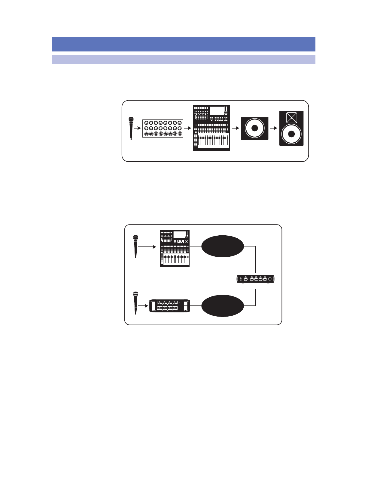
AVB networks behave very much like an analog audio system.
Like an analog audio system, audio networks consist of sources,
destinations, and intermediate processing along the way.
Let’s look at a simple live-sound setup:
mic
stagebox
mixer
active sub
active
loudspeaker
In the above example, an audio signal goes out of the microphone and into the stage
box. It then goes to the mixer, where the microphone signal is amplified, routed to
the appropriate output, and sent to an active subwoofer, where it is finally passed
through to the full-range loudspeaker. All of this is readily apparent to any audio
engineer just by looking at the diagram—a good thing because the skills required to
configure an analog system are nearly identical those needed by a network engineer.
Let’s compare the audio system above with components in a network:
mic
mic
mixer
Stage Box
AVB Switch
Input, Processing,
& Output
Input & Output
Link PoE
Blue= PoE On
(Hold to toggle)
White= PoE Off
1 2 3 4 5
SW5E
AVB SWITCH WITH PoE
PoE
Link PoE
1
2
3
4
5
In our network example, the microphones connected to the mixer and stagebox
can be freely available on either or both, depending on the routing.
Page 8
5
2 AVB Networking
2.2 What is AVB?
StudioLive™ Series III
AVB Networking Guide
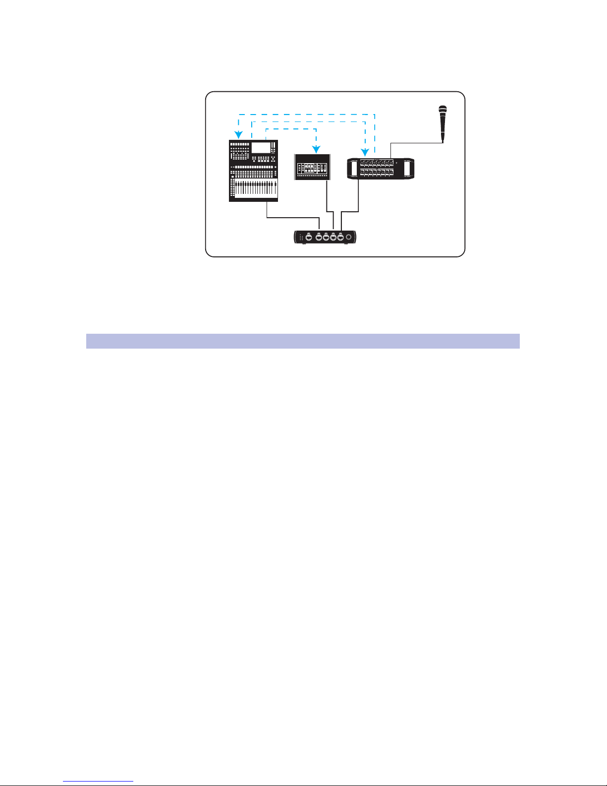
Let’s take a quick look at a microphone signal’s signal flow on a simple AVB network.
In the example below, the microphone’s signal is represented by the blue line:
mic
Mixer
Monitoring
Stage Box
AVB Switch
Link PoE
Blue= PoE On
(Hold to toggle)
White= PoE Off
1 2 3 4 5
SW5E
AVB SWITCH WITH PoE
PoE
Link PoE
1
2
3
4
5
Network
As you can see, tracing a device’s signal path becomes a little more complex
because the routing is handled entirely in the digital domain. But because
experienced audio engineers understand signal flow and are used to
troubleshooting problems in an analog system at the various points of
weakness, configuring an audio network becomes that much easier.
2.2 What is AVB?
AVB (Audio Video Bridging) is an extension to the Ethernet standard designed to
provide guaranteed quality of service, which simply means that audio samples will
reach their destinations on time. AVB allows you to create a single network for audio,
video, and other data like control information, using an AVB-compatible switch.
This enables you to mix normal network data and audio network data on the same
network, making it easier to create both simple and complex networks. Numerous
audio companies have adopted it, and more companies are adding it all the time.
Audio-over-Ethernet has become increasingly attractive in Pro Audio
applications especially for distribution in large-scale systems, such as those
used in sporting venues, concert halls, and education institutions. The problem
is that most solutions are proprietary, making these systems too expensive
and too complex for most smaller applications. AVB is intended to change
that by providing an open source collection of IEEE standards available
for use by the pro audio market and its manufacturing community.
AVB networking offers several features that make it ideal for audio applications:
• Long, light cable runs. A single lightweight CAT5e or CAT6 cable can
be run up to 100 meters (328 feet). This makes it easy to have audio
I/O located in different rooms (or even different venues in the same
building) and run multichannel audio between them in real time.
• Low, predictable latency. AVB provides latency of no longer than 2 ms
sending an audio stream point-to-point over up to seven “hops” (trips through
switches or other devices) on a 100 Mbps network. With higher speed
networks, many AVB devices support lower latencies and additional hops.
Please note that while PreSonus AVB products operate at faster Gigabit network
speeds, they are currently fixed to 2 ms of latency.
• Scalable, with high channel counts. AVB’s bandwidth is sufficient to carry
hundreds of real-time channels using a single Ethernet cable. This offers the
future possibility of expanding your system with additional devices that contain
different kinds of audio I/O, multiple controllers, and other useful functions.
Page 9

6
2 AVB Networking
2.3 How Does AVB Work?
StudioLive™ Series III
AVB Networking Guide
• Guaranteed bandwidth. AVB networks intelligently manage the data traffic
giving priority to AVB data. This means standard network traffic, such as Internet
streaming, won’t prevent your audio from being delivered reliably and on time.
• Integrated clock signal. In a digital audio system with multiple devices, having
a master clock is critical to maintaining audio fidelity. The AVB specification
defines such a clock to be accurately distributed to all devices in the system.
2.3 How Does AVB Work?
On the simplest level, AVB works by reserving a portion of the available
Ethernet bandwidth for its own traffic. Because packets of AVB data are
sent regularly in allocated slots within the reserved bandwidth, there are
no interruptions or interference, making AVB extremely reliable.
What makes AVB ideal for audio networking is that it splits network traffic into
real-time traffic and everything else. All real-time traffic is transmitted on an
8 kHz pulse. Anything that’s not real-time traffic is then transmitted around
that pulse. Every 125 µs, all real-time streams send their data. Other packets
are transmitted when there is no more real-time data ready to be transmitted.
To make sure that there is enough bandwidth available for all prioritized realtime traffic, the Stream Reservation Protocol (SRP, IEEE 802.1Qat) is used.
Every AVB compliant switch between each talker and listener will then make
sure sufficient bandwidth is available using SRP, making it a foundational
building block of the AVB standard. Every switch and AVB device on the
network must implement SRP and send real-time traffic at the 8 kHz pulse. If
one of the devices on the network does not employ this standard, then realtime traffic could be potentially delayed, causing jitter in the output.
2.4 AVB Hardware Components
In an AVB network, every device to and from which audio is flowing must
adhere to the AVB standard. These devices consist of the following types:
• AVB Talkers. These devices act as the source for an AVB
stream, sending out audio onto the network.
• AVB Listeners. These devices are the destinations
for the streams sent out by the Talkers.
• AVB Switches. This is the network hub to which every Talker and
Listener must be connected. At its most basic level, an AVB Switch
analyzes and prioritizes traffic on the network. It should be noted
that just like there can be multiple talkers and listeners on the
same AVB network, there can also be multiple AVB Switches.
• AVB Controllers. A controller can be a talker, a listener, or neither. These devices
handle routing, clock, and other settings for AVB devices using AVDECC.
The most important rule to keep in mind when setting up an AVB network is
that the talker (device sending audio) and listener (device receiving audio) must
be connected to an AVB-compatible switch. All the AVB devices on the network
must share a virtual clock that defines when the AVB packet should be played.
As previously mentioned, devices communicate on an AVB network as
“talkers” and “listeners.” An AVB talker transmits one or more audio streams
to the network. AVB listeners receive one or more of these streams from the
network. It should be noted that an AVB device, like the StudioLive Series
III mixers and NSB-series stage boxes, can be both a talker and a listener.
For example, StudioLive 32 can simultaneously “Talk” (send channels out
to the network) and “Listen” (receive channels from the network).
AVB devices stay in sync by selecting the best master PTP clock after the
devices connect with one another. This ensures that every AVB device on the
network will maintain precise timing, which is critical to audio quality.
Page 10
7
2 AVB Networking
2.5 Overcoming Latency
StudioLive™ Series III
AVB Networking Guide
The AVB switch guarantees that real-time audio data packets maintain
their timing without losing information. AVB switches do this by
allowing a maximum of 75% of each port to be used for AVB traffic.
This prevents non-AVB data from being delayed or lost.
When an AVB network is configured, the Talkers and
Listeners identify one another automatically.
2.5 Overcoming Latency
SRP works with the 802.1Qav Queuing and Forwarding Protocol (Qav) to ensure that
once bandwidth is reserved for an AVB stream, it is locked down from end to end.
Qav schedule time-sensitive streaming information to minimize latency. Together,
SRP and Qav make sure that all reserved media streams are delivered on time.
In this way, the AVB network has some intelligence as to how much non-media
traffic as well as how many media packets are on the system at any given
time. This means that on an AVB network, the worst case travel time is known
throughout the entire system. Because of this, only a small amount of buffering
is needed, lowering latency to 2 ms over seven switch hops on a 100 Mbps
Ethernet network. On gigabit networks, even lower latencies can be achieved.
2.6 Channels and Streams
AVB Streams can be thought of as the pipeline that carries a predefined
number of channels between two or more AVB devices. In a PreSonus
StudioLive Series III mixer, for example, there are seven input streams
and seven output streams available, each carrying eight channels.
It should be noted that each stream can carry any combination of eight channels.
The source for the eight channels within each AVB Send stream can be freely
routed from any input channel or bus on a StudioLive Series III mixer via the
Digital Patching menu. For complete information on Digital Patching, please refer
to the StudioLive Series III Owners Manual and UC Surface Reference Manual.
In addition to audio channels, each stream can carry clocking information from
the network’s global clock. Like all digital systems, devices on an AVB network
must receive media clock from a master source to maintain proper sync.
Channel 1
Channel 2
Channel 3
Channel 4
Channel 5
Channel 6
Channel 7
Channel 8
AVB STREAM
Page 11

8
2 AVB Networking
2.7 Clocking
StudioLive™ Series III
AVB Networking Guide
2.7 Clocking
All the audio traffic on an AVB network is synchronized using a global clock so
that audio can be played and recorded while remaining in time from multiple
sources. Obviously, the more audio traffic on a network, the more critical
this becomes. For users familiar with traditional digital audio devices (ADAT,
S/PDIF, etc.) the idea of a global clocking device will not seem unfamiliar.
PreSonus AVB devices have two clocks: one wordclock and one PTP clock.
All AVB devices on the network are synchronized to a common reference time using
the IEEE 802.1AS Precision Time Protocol (PTP). Each stream includes a presentation
time that all the devices in the network use to align their playback by comparing the
presentation time in each stream packet. An advantage to this design is that AVB
networking supports multiple simultaneous sample rates and sample clock sources
which is important for applications where audio and video need to be synchronized,
even though they travel along different paths with different sample rates.
2.7.1 Wordclock
Analog audio is transferred through a cable as a continuous electrical
waveform at almost the speed of light. Because of this, audio signal traveling
from one analog audio device to another arrives nearly instantaneously,
for all practical purposes. Therefore, you don’t have to synchronize analog
audio passing from one analog device to other analog devices.
Transferring digital audio is a very different matter. Computers and other
digital devices operate one step at a time, which happens very quickly but it’s
not instantaneous, and digital signals are not inherently in perfect time. While
uncompressed digital audio plays at a fixed rate (i.e., the sampling frequency), digital
clocks are not perfect; their frequency can drift, and they almost always have at
least some irregular errors, known as jitter. Therefore, two devices, each following its
own clock, are highly unlikely to stay in agreement about precisely when a sample
starts and ends. The result is usually an artifact, like a pop or a glitch in the audio.
To avoid this problem, all digital devices in communication with one another
need to follow a single master clock. That means the master clock must send a
signal that essentially says, “everyone start at this moment and follow me!”
Even if the master clock’s timing is imperfect, all the slave devices will
follow the timing errors exactly and will stay in sync with each other,
eliminating timing-related artifacts. In general, the better the master clock,
the better the resulting audio will sound, so whenever possible, use the
best clock you have, or experiment with your rig to find the best result.
Whenever digital audio devices are synchronized, it is necessary to designate
one device as the “master” wordclock device to which all other digital devices
are synced, or “slaved.” Once you’ve determined which device is to be your
master clock, you will need to sync the remaining digital devices.
The problem of designating a master wordclock is not handled by AVB and
must be set with an AVB controller. Depending on the device, this can be done
manually, by the user, or managed automatically. For example, when setting up
a StudioLive rack mixer as a stage box from a StudioLive console mixer, the rack
mixer is automatically setup to slave from the console mixer’s media clock.
Multiple unrelated wordclocks can co-exist on an AVB network. While there are a
few ways to match wordclocks between a talker and listener, PreSonus AVB devices
currently only support recovering the media clock by listening to the first AVB stream.
Page 12

9
2 AVB Networking
2.7 Clocking
StudioLive™ Series III
AVB Networking Guide
2.7.2 Precision Time Protocol (PTP)
Precision Time Protocol or PTP is used to synchronize clocks throughout a
computer network. PTP is capable of achieving clock accuracy in the submicrosecond range, making it suitable for local area networks that require
tight timing. Similar to wordclock, PTP uses a master-slave architecture
for clock distribution. This protocol defines clock master, link delay and
network queuing (both measurement and compensation), as well as
clock-rate matching and adjustments for Layer 2 network devices.
In this architecture, there are several different clock types:
• Ordinary Clock. This is a device with a single network connection and
either the sync source (master) or the sync destination (slave).
• Boundary Clock. This device has multiple network connections and can
accurately synchronize one network segment to another. A master clock is
selected for each segment in the system using a root timing reference generated
by the grandmaster clock. The grandmaster sends synchronization information
to the all the clocks on its network segment. The boundary clocks on that
segment then send accurate time to other network segments to which they’re
connected. Every AVB Talker is required to be capable of functioning as the
grandmaster; however any network node can be the grandmaster, as long as
it can either source or derive timing from a grandmaster-capable device.
On an AVB network, PTP generates timestamps so that every listener knows
when to playback the audio from the talker. In other words, the PTP clock is
used to align audio samples from multiple sources in time. Each grandmastercapable device broadcasts its clocking using announce messages. The best
master clock is then selected from the available announce messages.
2.7.3 Multiple Stream Reservation Protocol (MSRP)
Multiple Stream Reservation Protocol (MSRP) is the IEEE standard used to reserve
stream bandwidth for audio on an AVB network. This allows endpoints to
automatically route data and reserve bandwidth and eliminates the need for the
user to manually configure Quality of Service (QoS) across network devices. MSRP
looks at the end-to-end bandwidth that is currently available before an audio stream
is sent out. It then reserves a maximum of 75% of the total bandwidth available
on that AVB switch’s port. If the bandwidth is available, it is locked down along the
entire data path, from the Talker, out to every assigned Listener until it is released.
Bandwidth reservations are made based on talker and listener declarations
on the switch ports. Talker declarations come in several forms:
• Advertise Declaration. This declaration announces that a stream doesn’t
have any bandwidth or network constraints on its designated path. This means
that any destined Listener can create a reservation for QoS. Talkers advertise
messages contain all the information necessary to make the reservation.
• Failed Declaration. As its name indicates, this announces that a
stream is not available to a Listener because the necessary bandwidth
is not available or because of other limitations somewhere in the
network path between the Talker and the destined Listener.
As mentioned earlier, Listeners also make declarations within
an AVB network. These consist of the following types:
• Ready. One or more Listeners are requesting a stream and
sufficient bandwidth and resources are available from the Talker
along the network path to every intended Listener.
• Ready Fail. In this instance, one or more Listeners are requesting a
stream, but not all of them have sufficient bandwidth and resources
on the path to the Talker. In other words, at least one Listener has
encountered an obstacle and at least one Listener has not.
Page 13
10
2 AVB Networking
2.7 Clocking
StudioLive™ Series III
AVB Networking Guide
• Fail. When a Fail declaration is sent, one or more Listener has requested
a stream and every Listener that has done so does not have sufficient
bandwidth or resources in the network path to attach to the desired stream.
End-to-end stream reservation is successful as soon as the Listener receives the
Talker’s Advertise Declaration and the Talker receives the Listener’s Ready Declaration.
AVB stream reservation process:
AVB streams are only forwarded once a successful reservation is made. After the
streams stop, switch resources are then released and the process can begin again or
make room for other network traffic. In this way, the AVB standard ensures that audio
data streams always have the highest QoS and all other data is secondary or tertiary.
1
2
3
Link PoE
Blue= PoE On
(Hold to toggle)
White= PoE O
1 2 3 4 5
SW5E
AVB SWITCH WITH PoE
PoE
Link PoE
1
2
3
4
5
AVB Switch
Link PoE
Blue= PoE On
(Hold to toggle)
White= PoE O
1 2 3 4 5
SW5E
AVB SWITCH WITH PoE
PoE
Link PoE
1
2
3
4
5
AVB Switch
Link PoE
Blue= PoE On
(Hold to toggle)
White= PoE O
1 2 3 4 5
SW5E
AVB SWITCH WITH PoE
PoE
Link PoE
1
2
3
4
5
MANUFACTURING DATE
DESIGNED AND ENGINEERED IN BATON ROUGE, LA, USA • MANUFACTURED IN CHINA • PATENTS PENDING • “STUDIOLIVE”
and “PreSonus” ARE REGISTERED TRADEMARSK OF PRESONUS AUDIO ELECTRONICS • SD LOGO IS A TRADEMARK OF SD-3C, LLC
MANUFACTURING DATE
MANUFACTURING DATE
DESIGNED AND ENGINEERED IN BATON ROUGE, LA, USA • MANUFACTURED IN CHINA • PATENTS PENDING • “STUDIOLIVE”
and “PreSonus” ARE REGISTERED TRADEMARSK OF PRESONUS AUDIO ELECTRONICS • SD LOGO IS A TRADEMARK OF SD-3C, LLC
AVB Switch
Talker
Advertises
Talker
Ready
Talker
Sends Stream
Ready!
Ready!
Listener
Receives
Advertisement
Listener
Ready
Listener
Receives
Stream
Page 14
11
2 AVB Networking
2.7 Clocking
StudioLive™ Series III
AVB Networking Guide
2.7.4 Clocking a PreSonus AVB Network
Within the PreSonus AVB ecosystem, a StudioLive Series III mixer must be
used the master word clock for the network. For some devices, clocking is
handled automatically. For others, additional set-up is required. This section
will provide an overview of the steps required for proper system clocking.
EarMix 16M Personal Monitor Mixers
Because the EarMix 16M is a listener only, it defaults to clocking from the incoming
audio streams.As soon as you route an AVB Send to your EarMix 16M, it will sync to
the master mixer.
NSB-Series Stage Boxes
NSB-Series stage boxes are designed to provide both remote inputs and remote
outputs for StudioLive Series III mixers. Like the EarMix 16M, the NSB-series stage
boxes will default to external clock and sync to a StudioLive Series III mixer as soon as
AVB sends are routed to their outputs.
It is important to note that these AVB sends must be routed whether they are needed
or not. Let’s look at the common example of a StudioLive 16 console mixer with
two NSB 8.8 stage boxes. In some situations, the eight outputs on the second NSB
8.8 stage box may not be needed to pass audio. In this case, routing an AVB output
stream from the mixer to the stage box would still be required for proper clocking.
StudioLive Series III Mixers (Monitor Mixer Mode)
StudioLive Series III mixers provide a customized mode when used as Monitor mixer.
This mode allows them to retain independent control over their FlexMix outputs
while sharing input streams as well as the Main Mix with the Front-of-House mixer.
As soon as Monitor Mixer Mode is engaged on a StudioLive Series III rack mixer, its
clock is set to sync to the Front-of-House console as well. No further set-up is
required.
StudioLive Series III Rack Mixers (Stagebox Mode)
StudioLive Series III rack mixers also provide a customized mode to function as a
stage box for other StudioLive mixers. This mode allows them to share all their inputs
and outputs with the Front-of-House mixer, effectively disabling all DSP functionality.
As soon as Stagebox Mode is engaged on a StudioLive Series III rack mixer, its clock is
set to sync to the Front-of-House console as well. No further set-up is required.
FX C FX D
FX A FX B
EarMix Setup
Name: EarMix 16M
Apply
Apply All
1-8 Send Source: AVB Send 41-48
9-16 Send Source: AVB Send 49-56
EarMix 16M
AVB Send 9-16
AVB Send 9-16
AVB Send 9-16
AVB Send 9-16
AVB Send 9-16
AVB Send 9-16
AVB Send 9-16
AVB Send 9-16
AVB Send 9-16
AVB Send 9-16
FX C FX D
FX A FX B
EFFECTS MASTER MASTER CONTROL
AVB Inputs
Stagebox Setup
Preamp Permissions: All
Name: NSB 16.8
Output Stream: None
Apply
i
NSB 16.8
StudioLive 16: Send 41-48
StudioLive 16: Send 33-40
StudioLive 16: Send 49-56
StudioLive 16: Send 41-48
FX C FX D
FX A FX B
EFFECTS MASTER MASTER CONTROL
AVB Inputs
Stagebox Setup
Preamp Permissions: StudioLive 24
Name: StudioLive 24R
Mode: Monitor Mixer
Apply
i
StudioLive 24R
NSB 8.8
Monitor Mixer
Stand-alone
Stagebox
Monitor Mixer
FX C FX D
FX A FX B
EFFECTS MASTER MASTER CONTROL
AVB Inputs
Stagebox Setup
Preamp Permissions: StudioLive 24
Name: StudioLive 24R
Mode: Monitor Mixer
Apply
i
StudioLive 24R
NSB 8.8
Monitor Mixer
Stand-alone
Stagebox
Stagebox
Page 15

12
2 AVB Networking
2.7 Clocking
StudioLive™ Series III
AVB Networking Guide
StudioLive Series III Mixers (Standalone Mode)
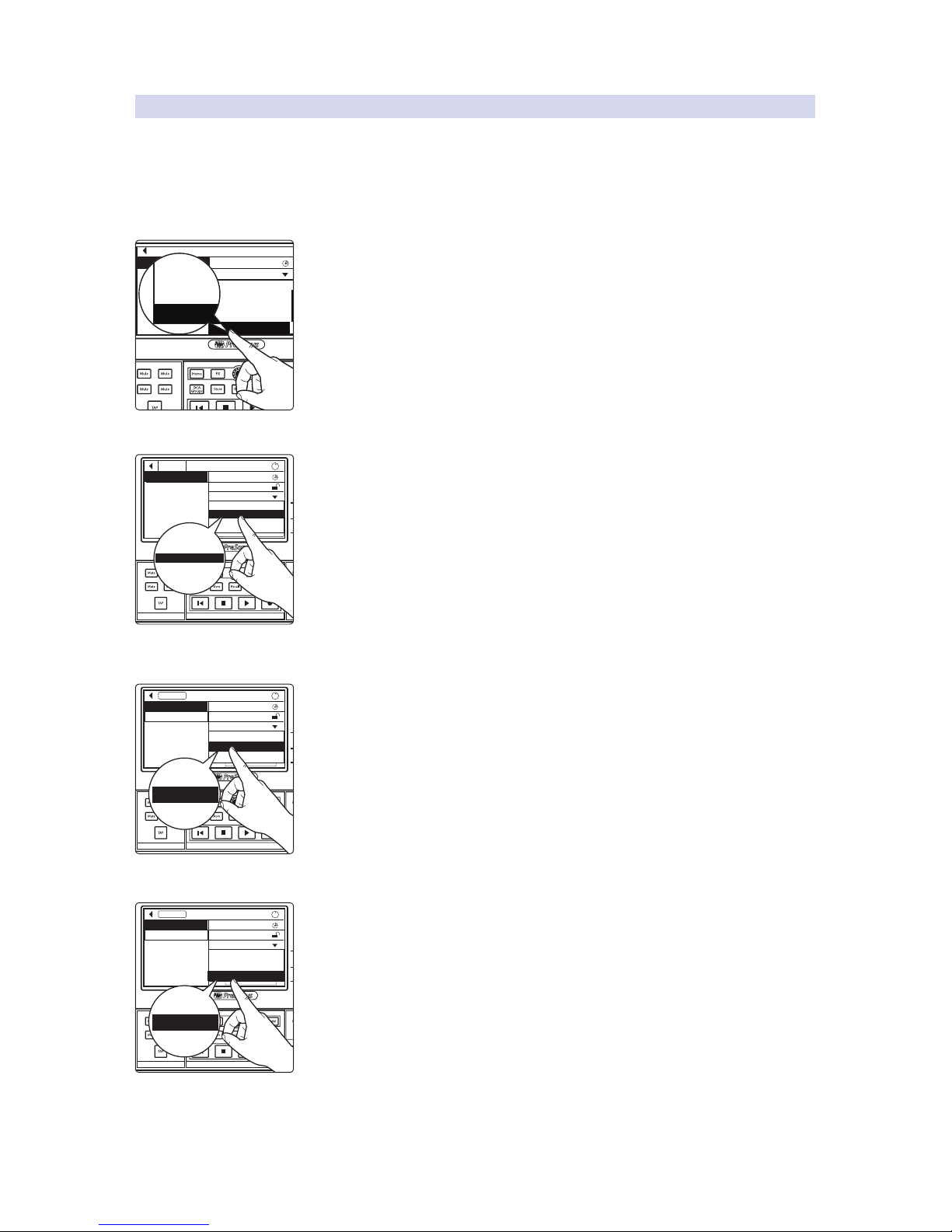
In applications where two or more mixers are on a network, functioning
independently, but configured to send and received streams to and from other AVB
nodes on the network, you must designate one mixer as the clock master.
To do this, simply set all other mixers to receive clock from the Network
Stream and be sure a stream is routed to the first AVB stream of each mixer
from the master mixer. Be sure to leave one mixer on its Internal clock.
On a StudioLive Series III console mixer, configuring external clocking can be done
from the System Menu located on the Home Screen.
On all StudioLive Series III mixers (rack or console), configuring external clocking can
be done from the Device Settings Menu in UC Surface.
FX C FX D
FX A FX B
EFFECTS MASTER MASTER CONTROL
AVB Inputs
Stagebox Setup
Preamp Permissions: StudioLive 24
Name: StudioLive 24R
Mode: Monitor Mixer
Apply
i
StudioLive 24R
NSB 8.8
Monitor Mixer
Stand-alone
Stagebox
Stand-alone
Permissions User Button Assgins
FirmwareFat Ch Load/Paste
Link Aux Mutes Bluetooth Reg.
Sample Rate:
48 kHz
Network Stream
Off
Med HighLow
HighLow
Network Clock:
Show Peak Hold:
LED:
Backlight:
Network Stream
Internal
FX C FX D
FX A FX B
Network Stream
Page 16

13
3 AVB Networking Basics
3.1 Selecting the Right Switch
StudioLive™ Series III
AVB Networking Guide
3 AVB Networking Basics
When configuring an AVB network, it is important to familiarize yourself
with the fundamental components. This section has been designed
to assist you in building your AVB network from the ground up.
3.1 Selecting the Right Switch
By definition, all AVB switches must adhere to every IEEE standard within
the AVB protocol. Ordinary LAN switches (managed or unmanaged)
used in everyday IT applications don’t have this same requirement and
do not support the protocols necessary for AVB networking.
All AVB switches are required to support the following:
• IEEE 802.1Q: Stream Reservation Protocol (SRP) and Traffic Shaping (FQTSS)
• IEEE 802.1AS: Time Synchronization using Generalized Precision
Time Protocol (gPTP) on each AVB enabled Ethernet port
These standards are critical for both reservation
management and tight, synchronized clocking.
3.1.1 PreSonus SW5E AVB Switch with PoE
The PreSonus SW5E AVB Switch with PoE is a 5-port AVB switch that is fully
compatible with all PreSonus AVB devices. In addition to adhering to the required
IEEE standards, the SW5E provides Power over Ethernet (PoE) on four of its five ports.
Power over Ethernet or PoE is an IEEE standard that allows electric power
to be provided over the same Ethernet cable used for data transfer,
similar to how Phantom Power provides enough current over an XLR
cable to power condenser microphones and active direct boxes.
The PreSonus EarMix 16M can be fully powered by PoE using a PreSonus
SW5E switch or any other standard AVB switch that provides it. It should
be noted that while the EarMix 16M can receive PoE, it does not pass that
power through to other devices. So, in order to power multiple EarMix
16M, each mixer must have a direct path back to a PoE AVB Switch.
SW5E AVB Switch
Audio, Data, and Power
EarMix 16M Personal Monitor Mixers
Link PoE
Blue= PoE On
(Hold to toggle)
White= PoE Off
1 2 3 4 5
SW5E
AVB SWITCH WITH PoE
PoE
Link PoE
1
2
3
4
5
Page 17
14
3 AVB Networking Basics
3.1 Selecting the Right Switch
StudioLive™ Series III
AVB Networking Guide
In situations where this is not possible, an external power supply may
be used to power each EarMix 16M. This also allows you to daisychain multiple units to a single port on your AVB switch.
SW5E AVB Switch
Audio, Data, and Power Audio and Data Audio and Data
EarMix 16M Personal Monitor Mixers
Page 18
15
3 AVB Networking Basics
3.2 Adding a Wireless Router
StudioLive™ Series III
AVB Networking Guide
3.2 Adding a Wireless Router
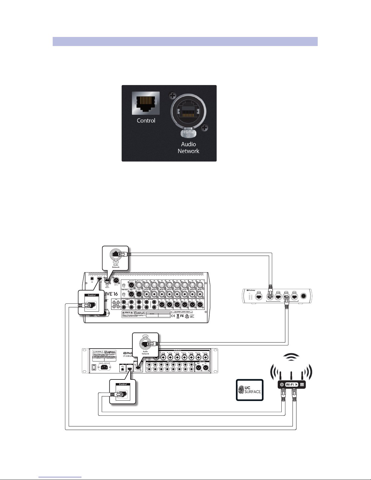
Many modern digital audio devices support some level of control over a Local Area
Network. Unlike its AVB counterpart, a standard LAN network does not prioritize the
traffic on it. While this is fine for control information and other simple data, it is less
than ideal for transmitting low-latency audio. PreSonus StudioLive Series III mixers
support both AVB and LAN networking, each with its own dedicated Ethernet port.
For StudioLive Series III mixers, the Audio Network connection should
attach to the AVB network, while the control port should be connected to
a wireless router, or an access point, so that the mixer can be controlled
remotely from UC Surface or QMix-UC. The control port should also be
used to network your mixer to your computer while using DAW mode.
It should be noted that while a wireless router can be connected to an
AVB switch, you would still need to connect both the Audio Network and
the Control port to a network configured in this manner. Because of this,
PreSonus recommends that you create two networks for your StudioLive
mixer: one dedicated to control data and a second dedicated to AVB data.
MANUFACTURING DATE
Link PoE
Blue= PoE On
(Hold to toggle)
White= PoE Off
1 2 3 4 5
SW5E
AVB SWITCH WITH PoE
PoE
Link PoE
1
2
3
4
5
StudioLive 16
StudioLive 32R
SW5E AVB Switch
iPad running UC Surface
Page 19
16
3 AVB Networking Basics
3.3 Choosing the Right Cables
StudioLive™ Series III
AVB Networking Guide
3.3 Choosing the Right Cables
AVB networks rely on a set of standards for cabling infrastructure to ensure
that network performance is both reliable and consistent. These standards
include specifications for the cable construction itself, as well as specifications
for the termination of cabling and physical connections to devices.
Deviations from these specifications can result in reduced performance
and even data loss, so it’s important to use the right cable for the job, and
to use good quality cable that meets the necessary specifications.
Cabling that is out of spec can result in dropped packets and intermittent
connections. For simple data networks, such as those used to stream video or
transfer files, it could just mean increased buffer times or transfer times. For live,
real-time audio, it can mean audible dropouts in audio or loss of audio altogether.
3.3.1 Cat5e and Cat6
While AVB itself doesn’t require gigabit Ethernet, PreSonus AVB product do
require this speed because of the stream- and channel-counts involved.
While this isn’t a function of the cables themselves (the devices and AVB
switches handle gigabit Ethernet), it is still an important consideration
to keep in mind when building your AVB network because you must
select Ethernet cable that is capable of supporting Gigabit speeds.
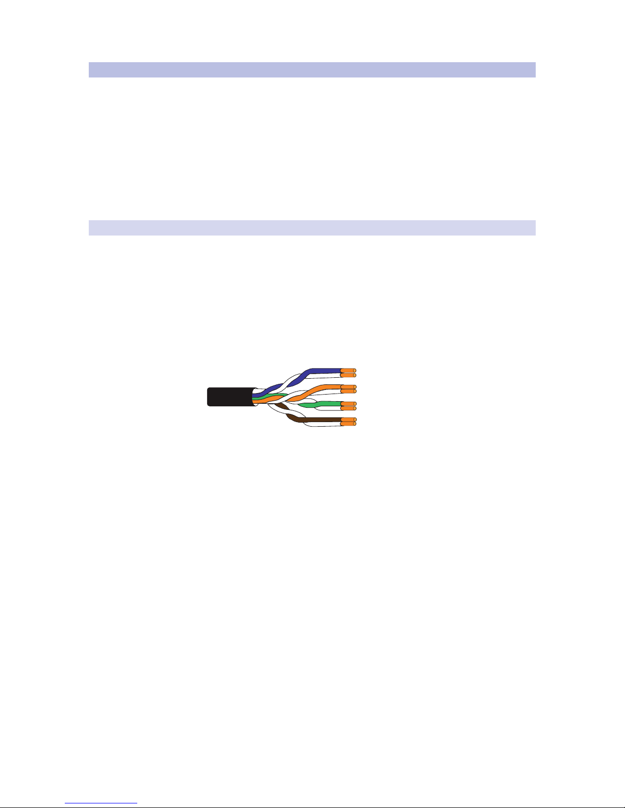
Copper-wire Ethernet networks generally use twisted-pair cable. Twisted
pair cabling is a type of wiring in which two conductors of a single circuit
are twisted together to cancel out electromagnetic interference (EMI) from
external sources, and reducing crosstalk between neighboring pairs.
AVB networks require the use of either CAT5e or CAT6 cables, both of which
support Gigabit speeds at lengths up to 100 meters, as specified by the TIA/
EIA-568 standard. CAT6 is designed to support speeds up to 10 Gb/s (10GBASE-T
or 10 Gigabit Ethernet), but it is backward compatible with CAT5e. The primary
differences between CAT5e and CAT6 cable are the wire gauge of the conductors
and the number of twists per inch in each wire pair. CAT6 cable uses heavier gauge
wire and more twists per inch, providing lower crosstalk, higher signal-to-noise
ratio, and an overall better performance rating than the CAT5e equivalent.
Which type of cable you choose for your application depends on several
factors. Network design, installation type (fixed or mobile), budget, and future
applications should all be considered when selecting the type of cable you
will use. CAT5e cable is usually slightly more cost effective, may be easier to
work with, and still fully supports Gigabit speeds, but Cat6 is generally a better
choice and is well worth the additional investment given its capacity for faster
speeds, especially when considering the future needs from your system.
Power User Tip: Always source your cable from a reputable vendor to ensure you are
purchasing a high-quality product that meets the industry and engineering specifications
it claims by its Category label (CAT5e or CAT6). Never purchase cables labeled CCA
(Copper Clad Aluminum), as it does not meet the TIA/EIA specifications for Cat5e and
Cat6 cabling.
Page 20
17
3 AVB Networking Basics
3.3 Choosing the Right Cables
StudioLive™ Series III
AVB Networking Guide
3.3.2 Shielded vs. Unshielded
Conductor
Insulation
Pair shield
Sheath
Shielded Twisted Pair (STP)
Unshielded Twisted Pair (UTP)
Conductor
Insulation
Sheath
Conductor
Insulation
Pair shield
Cable shield
Sheath
Shielded and Foiled Twisted Pair (STP)
Foiled Unshielded Twisted Pair (UTP)
Conductor
Insulation
Sheath
Cable shield
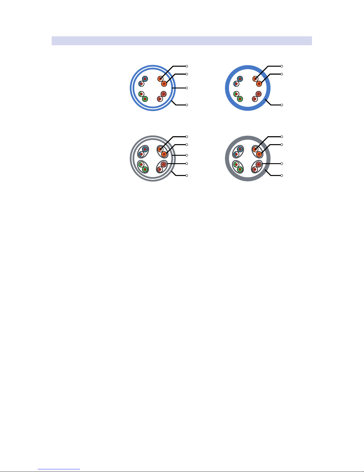
Whether you use CAT5e or CAT6 cable, you will have the option to use Shielded
or Unshielded cable. Both cable types can be used for AVB networking and have
advantages, depending on the type of AVB installation you are designing.
Shielded twisted-pair (STP) cables provide a barrier to help interference,
especially electromagnetic interference (EMI). STP cable is constructed
with additional electrical shielding along the length of the cable as well as
specially constructed plugs that electrically connect and properly ground the
cable shielding to the device connected at each end. Originally developed
for industrial applications, shielded cable is ideal for fixed installations
where Ethernet cable must be run near power, fluorescent lighting, etc.
Like a balanced analog cable, STP cables have to be grounded, so you’ll
need to use STP-compatible RJ45 connectors. Most XLR-style locking
Ethernet connections you will find used on Pro Audio equipment, like
the StudioLive Series III mixers and NSB stage boxes, are designed to be
able to support both shielded and unshielded cable connections.
There are some specific use cases which might call for shielded Ethernet
cable to prevent electromagnetic interference (EMI) or radio-frequency
interference (RFI) from affecting the performance of the cable. It should be
noted that if shielded cable is used but not implemented correctly, it can
introduce problems and make things worse than using unshielded cable.
As with everything in audio, if you are not experienced in installation or
design, it’s well worth the investment to consult a professional who is.
There are several different acronyms commonly used to describe shielded cables
where the twisted pairs are not themselves individually shielded. These cable
types rely on an overall shield or screen to filter out external noise. While you
may find them used synonymously, there are important differences to note:
• SF/UTP. This cable features a braided screen (S) and a foil shield (F) that
surrounds unshielded twisted pairs (UTP). Cables with an overall braided
screen are great for applications that need extra protection from EMI.
• S/UTP. This cable features a braided screen (S)
surrounding unshielded twisted pairs (UTP).
• F/UTP (FTP). This cable uses an overall foil shield (F) to protect
the unshielded twisted pairs (UTP) and is essentially very similar
to a simple UTP cable, offering very little protection.
Page 21
18
3 AVB Networking Basics
3.3 Choosing the Right Cables
StudioLive™ Series III
AVB Networking Guide
• S/FTP. This cable features an overall braided screen (S) encasing foil-
screened twisted pairs (FTP). In this design, each twisted pair is protected
by its own foil screen to limit the amount of crosstalk between them.
• F/FTP. In this design, an overall foil screen (F) protects
individually wrapped foil-screen twisted pairs (FTP).
• U/FTP. This design removes the overall screen and relies only on the
individual foil-wrapped twisted pairs (FTP) to limit interference.
Unshielded twisted pair (UTP) and its cousins, U/FTP and F/UTP are lighter
weight and more flexible. These cable types have the benefit of being easier
to terminate and much more flexible than their shielded counterparts.
What type of cable you select depends largely on your application and the
amount of environmental interference you anticipate encountering.
3.3.3 Solid-core vs. Stranded
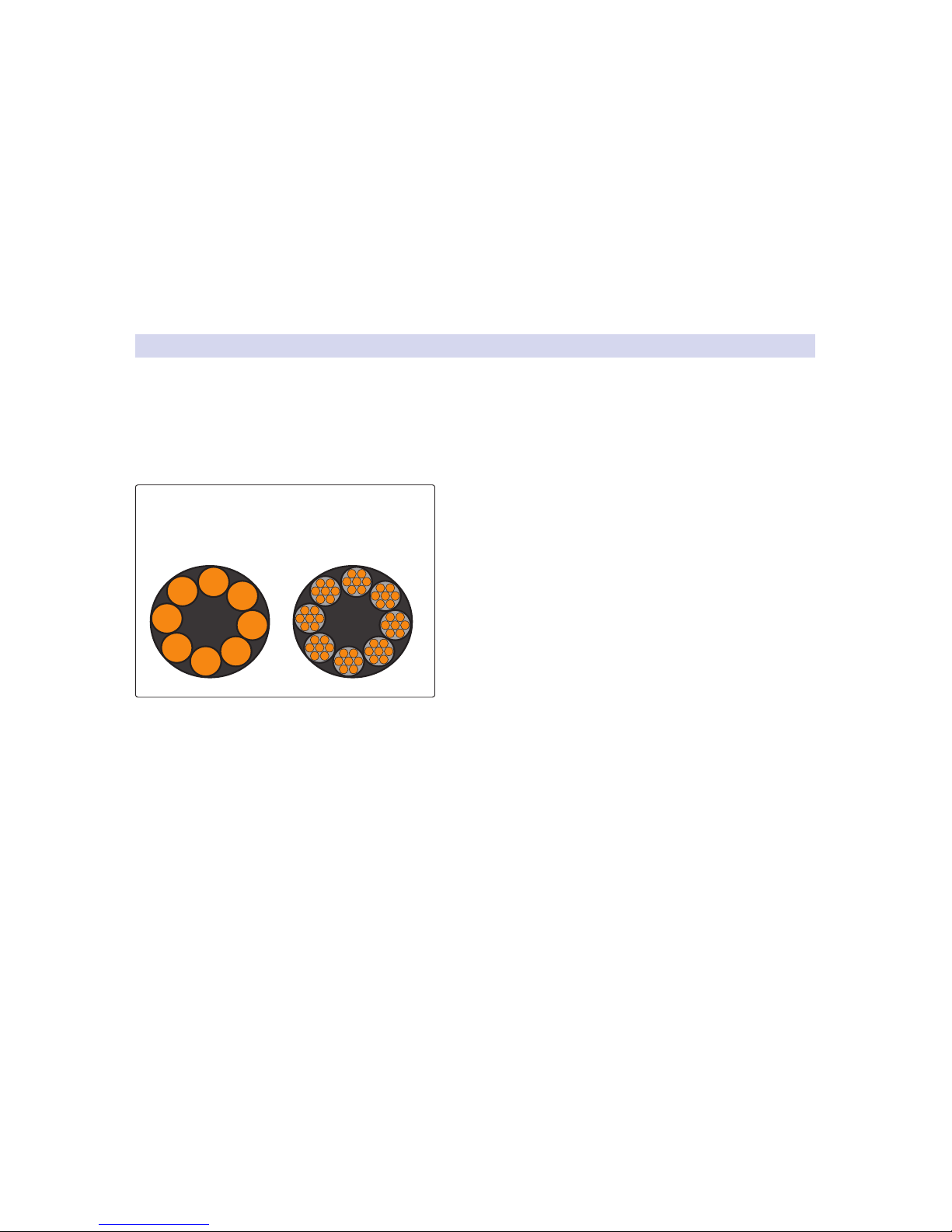
Another thing to keep in mind when selecting Ethernet cable is whether it
is solid- or stranded-core. In a solid-core cable, each of the conductors is a
single copper wire, which is a better fit for installations and long cable runs
(more than 70m). Stranded-core cables use multiple, thinner copper wires
for each conductor, making them more flexible and easier to handle. This
makes stranded-core cable a better fit for touring and shorter cable runs.
Most Ethernet cable is solid-core, constructed using solid
insulated bare copper conductors for each of the eight wires
in the four twisted pairs of the cable. These cables are meant
to be used in permanent and semi-permanent installations,
and are designed for longer distance horizontal and
backbone cable runs. All CAT5e and CAT6 solid UTP cables
are designated with a minimum bend radius for performance
standards. The bend radius is the minimum radius a cable
can be bent without kinking it, which can lead to damage
and shorten its life. The minimum bend radius for Category 5,
5e, and 6 cable is four times the cable diameter, or about one
inch. Proper cable installation is essential in order to
maximize the performance of the cable.
In the case of a mobile live sound operation, with frequent setup and teardown,
solid-core Ethernet cable probably isn’t the best choice, as it’s generally stiffer and
not conducive to easy layout and flat deployment runs. Solid-core cables should not
be over-flexed, bent, or twisted beyond the cable’s recommended specifications,
as you risk damaging the cable, causing it to underperform or even fail.
Stranded Ethernet cables have multiple strands (typically 7 strands per
conductor) of insulated bare copper conductors. These cables are typically
used for patch cords/cables connecting devices to the network, but because
these cables are more flexible than solid conductors, they are an excellent
choice for portable uses and applications where repeated flexing is common,
such as frequent setup and teardown of a live sound PA system.
A Quick Note About Tactical Ethernet Cable
When you need Ethernet cable that is intended specifically for harsh environments
with repeated deployment, a special type of cable should be considered. Tactical
cable generally uses stranded-wire construction for flexibility and durability,
as well as employing a heavy, often rubberized outer jacket in addition to the
lightweight PVC jacket (sometimes referred to as “up-jacketed”). Tactical Ethernet
cable has a very similar feel and handling characteristics to balanced audio
cable, and is much more rugged than common solid-core cable used for in-wall
building installation, making it ideal for Pro Audio and Live Sound applications.
Inside your Ethernet cable
Solid core Stranded
Page 22

19
3 AVB Networking Basics
3.3 Choosing the Right Cables
StudioLive™ Series III
AVB Networking Guide
3.3.4 Plug Termination
Making your own Ethernet cables can be a great way to save money, and
allows you to create cables to fit your needs and specifications exactly. If
you choose to make your own Ethernet cables, it’s important to be aware of
some possible pitfalls and follow some important general guidelines.
Most RJ-45 connectors are designed to be used with either solid-core or stranded
cable; however, you should always confirm the connector’s compatibility
to the type of cable you are deploying. Using a plug designed for one type
of cable with the wrong cable type can produce unreliable results.
The same is true for CAT5e and CAT6 cable connectors. Most RJ-45
connections are only meant to be used specifically with one or the
other. Additionally, some connectors are designed for specific wire
gauges and cable diameters, so, again, you should always confirm your
connector’s compatibility with the specific cable you are using.
Power User Tip: Just like sourcing cable, it’s important to source quality connector from a
reputable vendor. The connector itself is one of the most crucial pieces in the equation.
Even the highest quality cable is only as good as the connections terminating each end.
3.3.5 T568A or T568B
There are two wiring pinouts defined by TIA/EIA standards: T568A and T568B.
Currently, T568B is used almost universally in the U.S. - a legacy of analog telephone
compatibility - while T568A is more common worldwide. Either is perfectly
acceptable as long as you are consistent. If you’re doing a new wiring install, it’s
best to choose one or the other and stick with it throughout your network. If
you’re making new cabling and not sure about an existing wiring install, don’t
worry, it’s even okay to intermingle the two standards for the most part. The most
important consideration and the only rule you absolutely must follow is that for
a given cable or run, you must use the same wiring standard on both ends.
3.3.6 Twisted Pair Tips
When building your own twisted-pair Ethernet cable, it is crucial that
the twists are maintained as close as possible to the contact termination
within the plug as possible. You’ll also want to make sure that the wire pairs
running to adjacent pins are parallel inside the plug body all the way to
the pin. You don’t want different pairs wrapped around each other or have
wires bunched up inside the plug and pressed against each other.
Trimming the wire pairs to the proper length is also crucial, as you
want to make sure that the back-crimp of the plug is clamping
down on the cable jacket, not the wires themselves.
You might be surprised at how easy it is to create a poor termination and how
narrow the window is between a working cable and a failing cable. The crosstalk
performance and EMI rejection capabilities of Ethernet cable, which ensure it will
function up to its rated specification, are entirely dependent on maintaining these
relationships of the wires within the cable and the plug termination. A little attention
to detail goes a long way in this respect. Again, if you are unfamiliar with proper
termination techniques, PreSonus recommends consulting with a professional.
Page 23
20
3 AVB Networking Basics
3.4 Understanding Hops
StudioLive™ Series III
AVB Networking Guide
3.4 Understanding Hops
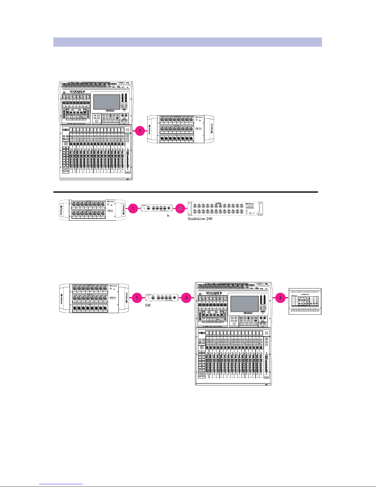
In its simplest terms, 1 LAN is equal to 1 hop, where the LAN is the span between
two AVB switches (also known as ‘bridges’). Take a look at the examples below. These
examples are fairly straightforward: one LAN connection equals one AVB hop.
Link PoE
Blue= PoE On
(Hold to toggle)
White= PoE O
1 2 3 4 5
SW5E
AVB SWITCH WITH PoE
PoE
Link PoE
1
2
3
4
5
StudioLive 24R
StudioLive 16
NSB 16.8
NSB 8.8
SW5E AVB Switch
Sub/Matrix Sub/Matrix
Sub/Matrix
Sub/Matrix
Sub/Matrix
Sub/Matrix
Sub/Matrix
Sub/Matrix
Sub/Matrix
Sub/Matrix
Sub/Matrix Sub/Matrix
Sub/Matrix
Sub/Matrix
Sub/Matrix
Sub/Matrix
MIX SELECT
BANK
Page
(Insert)
Input Mic/Line Assign
Channel
Stereo
Preset
CompGate
Processor EQ / Dyn
MonitorFX C FX D
FX A FX B
EFFECTS MASTER MASTER CONTROL
OL
-2
-12
-24
-36
-48
-65
-2
-12
-24
-36
-48
-65
Level
Mix 1
Mix 3
Mix 5
Mix 7
Mix 2
Mix 4
Mix 6
Mix 8
Mix 9
Mix 11
Mix 13
Mix 15
Mix 10
Mix 12
Mix 14
Mix 16
Ch 11Ch 22Ch 43Ch 44Ch 55Ch 66Ch 7
7
1
1 2
In this next example, the EarMix 16M has a third hop because the input
channels from the NSB16.8 stage box are being routed to the StudioLive
16, where they are processed by the Fat Channel and added to FlexMixes
before they are then sent back out to the network and on to the EarMix 16M,
making three total hops between the NSB 16.8 and the EarMix 16M.
Treble
Pan
Limit
Mid Freq Mid Level
Bass
PhonesLine OutAux Input
L
R
OL
-6
-18
-40
Level
Network
SELECTED CHANNELGLOBAL MASTER
1 2 3 4 5 6 7 8 9 10 11 12 13 14 15 16
Recall
Link
Store
Group Mute
Solo
Mono
Select
Link PoE
Blue= PoE On
(Hold to toggle)
White= PoE O
1 2 3 4 5
SW5E
AVB SWITCH WITH PoE
PoE
Link PoE
1
2
3
4
5
SW5E AVB Switch
EarMix 16M
StudioLive 16
NSB 16.8
Sub/Matrix Sub/Matrix
Sub/Matrix
Sub/Matrix
Sub/Matrix
Sub/Matrix
Sub/Matrix
Sub/Matrix
Sub/Matrix
Sub/Matrix
Sub/Matrix Sub/Matrix
Sub/Matrix
Sub/Matrix
Sub/Matrix
Sub/Matrix
MIX SELECT
BANK
Page
(Insert)
Input Mic/Line Assign
Channel
Stereo
Preset
CompGate
Processor EQ / Dyn
MonitorFX C FX D
FX A FX B
EFFECTS MASTER MASTER CONTROL
OL
-2
-12
-24
-36
-48
-65
-2
-12
-24
-36
-48
-65
Level
Mix 1
Mix 3
Mix 5
Mix 7
Mix 2
Mix 4
Mix 6
Mix 8
Mix 9
Mix 11
Mix 13
Mix 15
Mix 10
Mix 12
Mix 14
Mix 16
Ch 11Ch 22Ch 43Ch 44Ch 55Ch 66Ch 7
7
1 2 3
The more switches or devices that are cascaded, the more potential for additional
hops being added between devices on your network. As hops are added,
the potential for the latency between the source and destination to exceed
the limits set by the AVB specification is increased. Because of this, PreSonus
recommends a maximum of six hops between source and destination.
Page 24
21
3 AVB Networking Basics
3.5 Network Topologies
StudioLive™ Series III
AVB Networking Guide
3.5 Network Topologies
AVB provides several different methods of Network topology. This section
will outline the three different methods of connecting your PreSonus AVB
network. It is important to note that these three different topologies can be
used individually or combined depending on your particular application.
When deciding which method or methods will best suit your needs,
take into consideration your channel count, system latency, the number
of locations, as well as future needs to expand your system.
3.5.1 Point-to-Point (P2P)
A point-to-point or P2P network is the simplest to design. While not technically
a network in and of itself, a Point-to-Point configuration relies on networking
protocols in order for two devices to transmit data to one another.
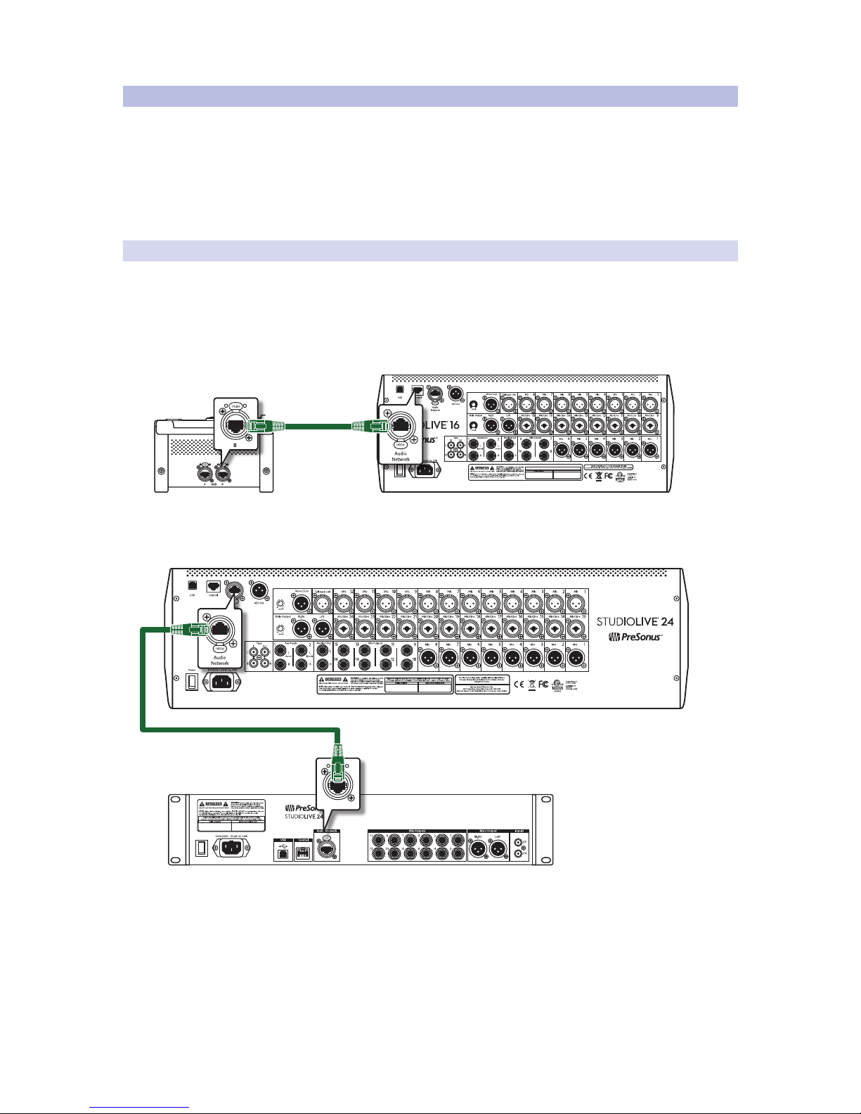
The most common example of this type of topology is a digital
mixer, like a StudioLive Series III console mixer, connected to
a network stage box, such as an NSB 8.8 or NSB 16.8:
MANUFACTURING DATE
DESIGNED AND ENGINEERED IN BATON ROUGE, LA, USA • MANUFACTURED IN CHINA • PATENTS PENDING • “STUDIOLIVE”
and “PreSonus” ARE REGISTERED TRADEMARSK OF PRESONUS AUDIO ELECTRONICS • SD LOGO IS A TRADEMARK OF SD-3C, LLC
Ethernet cable
NSB16.8 AVB Network Stagebox
Side View
StudioLive 16 Digital Console Mixer
Rear View
Another example is created when using a StudioLive Series III console mixer
at Front-of-House and a StudioLive Series III rack mixer in Monitor mode:
StudioLive 24 Digital Console Mixer
Rear View
StudioLive 24R Digital Console Mixer
Rear View
In both of these examples, an Ethernet cable is run from one device to the other
and the routing is handled efficiently from the console mixer’s touchscreen.
Page 25
22
3 AVB Networking Basics
3.5 Network Topologies
StudioLive™ Series III
AVB Networking Guide
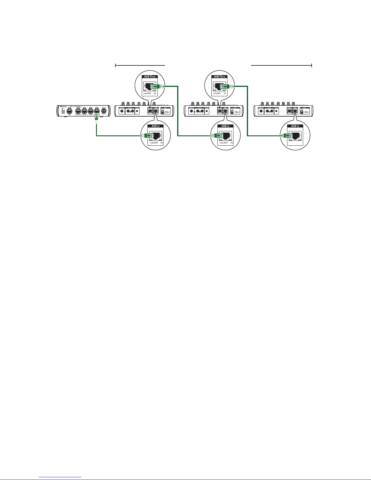
3.5.2 Daisy-Chain
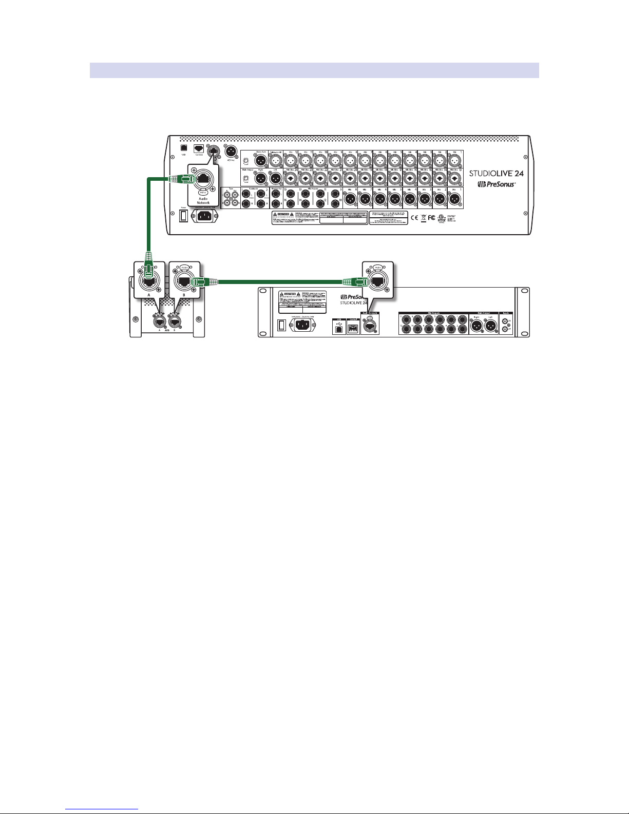
A daisy-chain topology allows you to connect devices serially. This configuration
requires a device have a built-in AVB switch that provides an additional port, like the
PreSonus NSB-series stage boxes and EarMix 16M personal monitor mixers. Because
of this, when connecting a simple network, you can connect your devices as follows:
StudioLive 24 Digital Console Mixer
Rear View
StudioLive 24R Digital Console Mixer
Rear View
NSB 8.8 AVB Network Stagebox
Side View
Page 26
23
3 AVB Networking Basics
3.5 Network Topologies
StudioLive™ Series III
AVB Networking Guide
3.5.3 Star
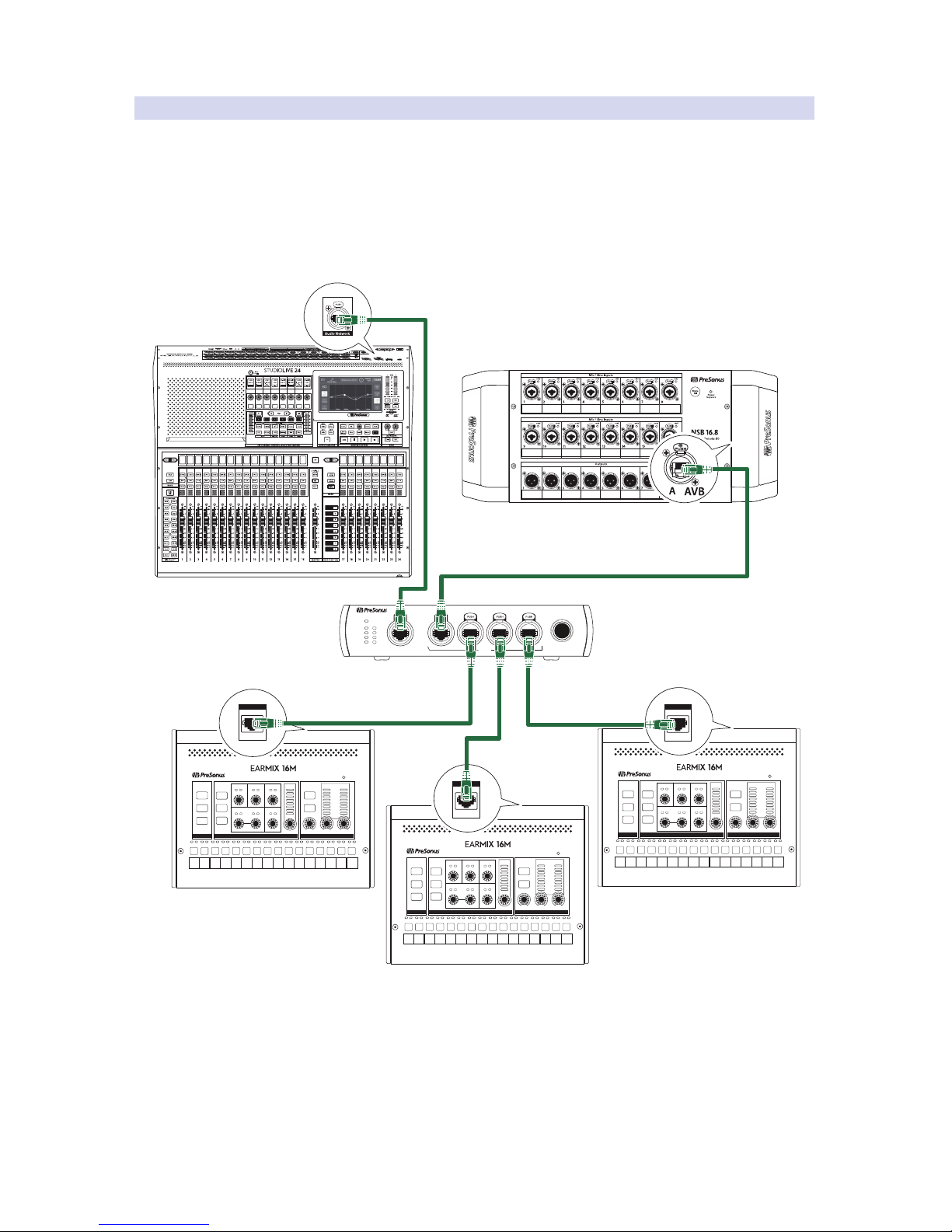
It is important to mention that the Daisy-chain topology creates the potential
for additional and unnecessary hops that could be omitted when using a
centralized AVB Switch. This is where the Star topology becomes ideal for
networks that require the use of more than just a handful of devices.
A star topology utilizes the network’s bandwidth more efficiently. It also minimizes
hops and the additional latency that can come with it. Star networks are based
around a centrally located switch or switches. All the nodes on the network
are connected to this switch, so there are fewer hops between devices.
Link PoE
Blue= PoE On
(Hold to toggle)
White= PoE O
1 2 3 4 5
SW5E
AVB SWITCH WITH PoE
PoE
Link PoE
1
2
3
4
5
StudioLive 24 Digital Console Mixer
NSB 16.8 AVB Network Stagebox
SW5E AVB Switch
Treble
Pan
Limit
Mid Freq Mid Level
Bass
PhonesLine OutAux Input
L
R
OL
-6
-18
-40
Level
Network
SELECTED CHANNELGLOBAL MASTER
1 2 3 4 5 6 7 8 9 10 11 12 13 14 15 16
Recall
Link
Store
Group Mute
Solo
Mono
Select
Treble
Pan
Limit
Mid Freq Mid Level
Bass
PhonesLine OutAux Input
L
R
OL
-6
-18
-40
Level
Network
SELECTED CHANNELGLOBAL MASTER
1 2 3 4 5 6 7 8 9 10 11 12 13 14 15 16
Recall
Link
Store
Group Mute
Solo
Mono
Select
EarMix 16M Personal Monitor Mixer
Treble
Pan
Limit
Mid Freq Mid Level
Bass
PhonesLine OutAux Input
L
R
OL
-6
-18
-40
Level
Network
SELECTED CHANNELGLOBAL MASTER
1 2 3 4 5 6 7 8 9 10 11 12 13 14 15 16
Recall
Link
Store
Group Mute
Solo
Mono
Select
EarMix 16M Personal Monitor Mixer
EarMix 16M Personal Monitor Mixer
AVB In
Link/ACT 1G
AVB In
Link/ACT 1G
AVB In
Link/ACT 1G
Star topologies are easily expanded, making them a great solution for dynamic
applications. For devices that support PoE (Power over Ethernet), like the EarMix
16M, a star topology provides the added benefit of delivering audio and data
connectivity as well as power, when using a PoE switch, like the SW5E.
Page 27
24
4 Configuring Your AVB Network
4.1 Using AVB with a StudioLive Series III Mixer and a Mac
StudioLive™ Series III
AVB Networking Guide
4 Configuring Your AVB Network
4.1 Using AVB with a StudioLive Series III Mixer and a Mac
StudioLive Series III mixers allow you to record and playback audio over AVB on any
Mac that supports AVB. A single computer can be used both to control and to record
from the StudioLive, or separate computers can be used for control and audio.
Note: At the time of publication Apple only supports connecting one computer via AVB.
Once a StudioLive Series III mixer has been selected as an AVB audio device for an Apple
computer, no audio can be routed to or from that mixer without using Apple’s AVDECC
controller. Because of this, PreSonus recommends using USB for recording on small AVB
networks containing only PreSonus devices.
4.1.1 What You Will Need
• StudioLive Series III mixer
• An AVB-compatible Mac running 10.9.5 or later. Any Mac with a
Thunderbolt connection should provide hardware support for AVB.
• If your computer does not have a built-in Ethernet port, you will also need a
Thunderbolt-to-Ethernet adapter. USB-to-Ethernet adapters do not support AVB.
Note: Recording over AVB is not supported while using Stagebox mode with your
StudioLive Series III mixer. Connecting a Mac to your AVB network with your StudioLive
mixer enabled as an AVB device will disable Stagebox mode.
4.1.2 Making the Connections
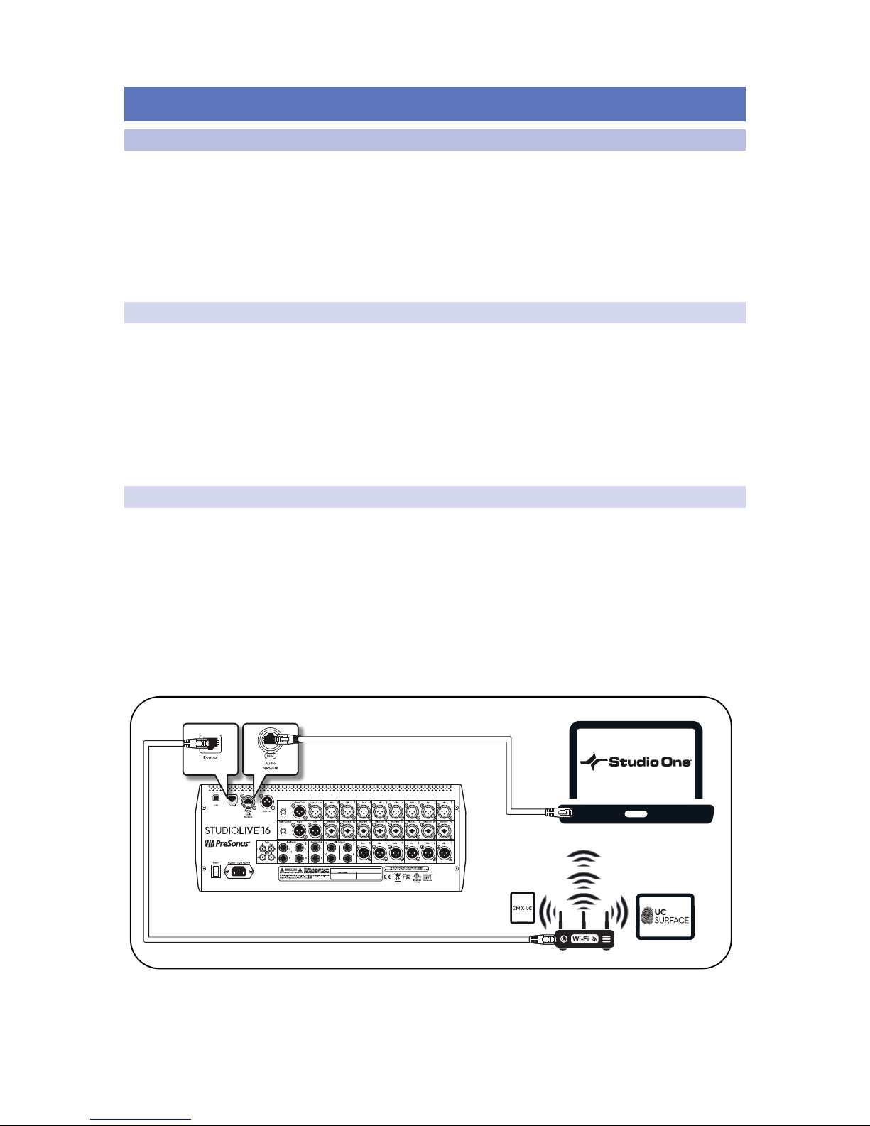
If you would like to remote control the mixer using UC Surface or QMix-UC,
the control port on the back of the mixer must be connected either directly
to a control device or to the same wireless network as the device running the
control software. The easiest configuration is to connect a wireless router to
the mixer’s control port and then connect your computer or other remote
devices to the router using either wired or wireless connections. If you
need AVB audio between more than just the mixer and the one computer,
you can incorporate an AVB switch to create a full AVB network.
Note: StudioLive Series III mixers cannot be remotely controlled over the audio
network connection.
MANUFACTURING DATE
DESIGNED AND ENGINEERED IN BATON ROUGE, LA, USA • MANUFACTURED IN CHINA • PATENTS PENDING • “STUDIOLIVE”
and “PreSonus” ARE REGISTERED TRADEMARSK OF PRESONUS AUDIO ELECTRONICS • SD LOGO IS A TRADEMARK OF SD-3C, LLC
iPad running UC Surface
Android running QMix-UC
Page 28
25
4 Configuring Your AVB Network
4.1 Using AVB with a StudioLive Series III Mixer and a Mac
StudioLive™ Series III
AVB Networking Guide
4.1.3 Setting Up Your Mac
When a StudioLive mixer is configured as an AVB audio interface for your Mac
using Core Audio, MacOS will acquire the AVB device, and prevent any other AVB
device from sending or receiving streams to or from the mixer. Because of this,
PreSonus recommends using the USB connection for recording and playback
when a StudioLive mixer is used as a part of a PreSonus AVB ecosystem network.
If your Mac doesn’t have an Ethernet port, you can connect your mixer via Ethernet
using a Thunderbolt-to-Ethernet adapter. USB-to-Ethernet adapters cannot be used
because the USB chipset used in Mac computers does not support AVB Ethernet.
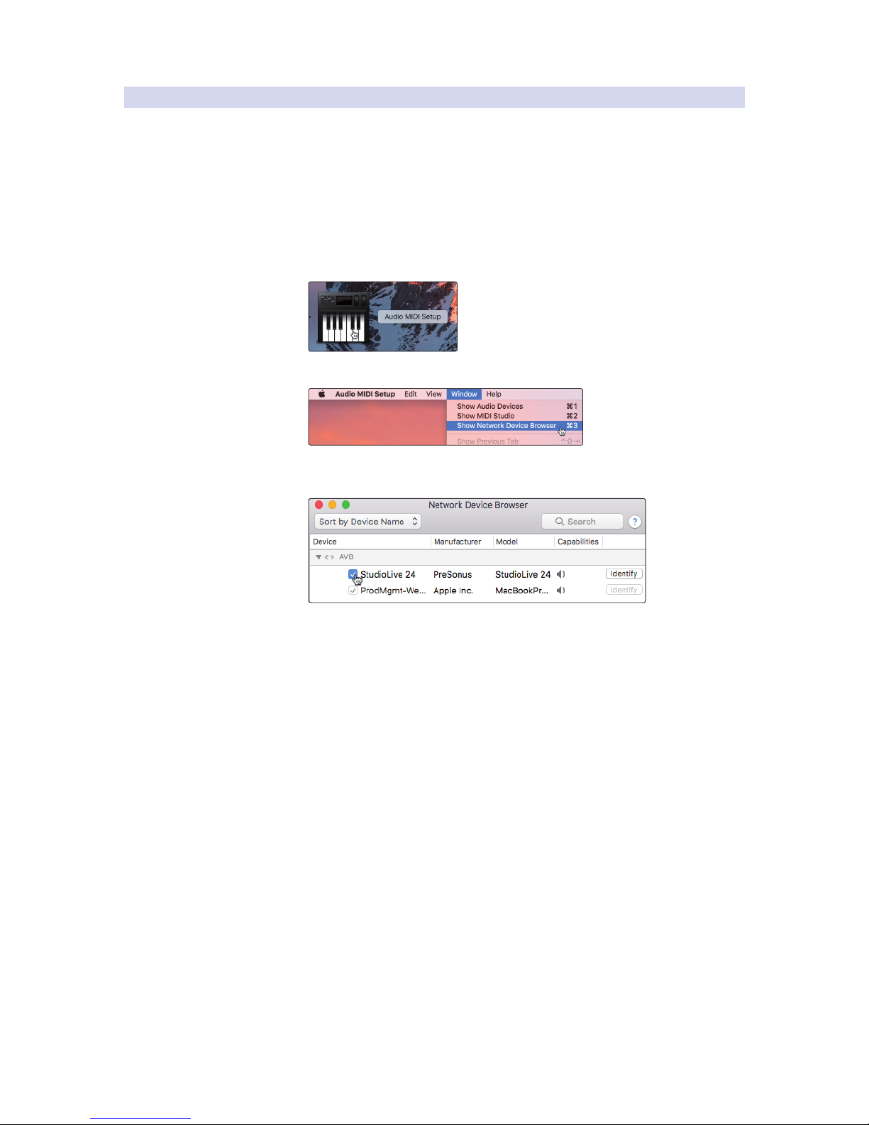
1. Open Audio/MIDI Setup.
2. Go to Window>Show Network Devices Browser.
3. Check the box next to your mixer to enable it as a Core
Audio device over AVB (this may take a moment)
Once your computer has successfully connected to your StudioLive Series III mixer,
your mixer will appear in Audio MIDI Setup as an available audio device that you can
use with any software that supports Core Audio (Studio One, Pro Tools, Logic, etc.).
Page 29
26
4 Configuring Your AVB Network
4.2 NSB-series Stage Box with a StudioLive Series III Console Mixer
StudioLive™ Series III
AVB Networking Guide
4.2 NSB-series Stage Box with a StudioLive Series III Console Mixer
NSB-series stage boxes can be configured from the touchscreen on any
StudioLive Series III console mixer. It should be noted, however, that UC Surface
configuration is also available. Please review Section 4.3 for instructions.
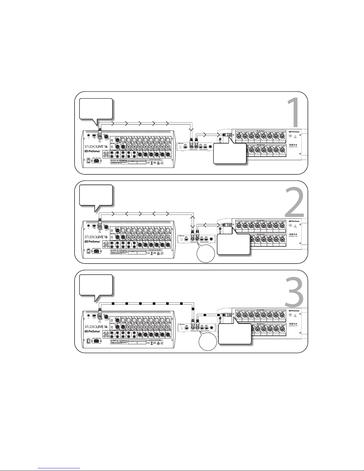
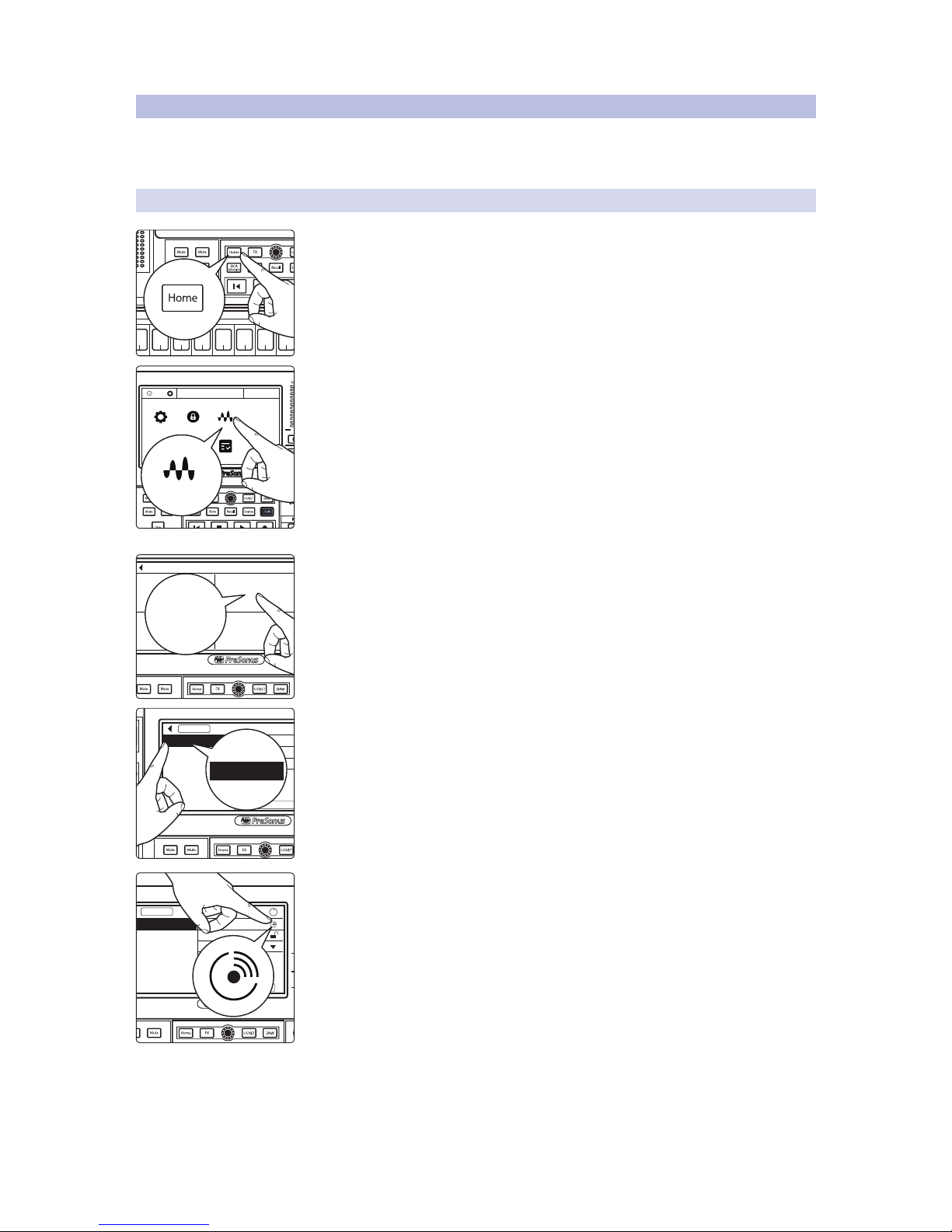
4.2.1 Step 1: Connect Your Stage Box to Your Mixer
1. Press the Home button on your StudioLive Series III mixer.
2. Press the Audio Routing icon on the Touchscreen.
3. Press the Stagebox Setup button on the Touchscreen.
4. Select the NSB-series stage box from the list on the left.
Power User Tip: In applications where you are using multiple NSB-series stage boxes
of the same model, you can press the Identify button. This will flash the Power
Network LED on the front of the selected NSB stage box from green to red, allowing
you to quickly locate your selection.
FX C FX D
FX A FX B
EFFECTS MASTER MASTER CONTROL
-2
-12
-24
-36
-48
-65
Ch 66Ch 77Ch 88Ch 9
9
Ch 10
10
Ch 1111Ch 1212Ch 13
13
MonitorFX C FX D
FX A FX B
1
Ch. 1
TB
System Global Lockout Audio Routing
UtilsCapture
Talkback Edit
Voume 0.5 dB
Audio Routing
FX A FX B
AVB Input Streams
Audio Routing
Stagebox Setup
Digital Patching
Earmix Setup
Stagebox Setup
FX A FX B
AVB Inputs
Stagebox Setup
Preamp Permissions: All
Name: NSB 16.8
Output Stream: None
Apply
NSB 16.8
NSB 16.8
AVB Inputs
Stagebox Setup
Preamp Permissions: All
Name: NSB 16.8
Output Stream: None
Apply
i
Page 30
27
4 Configuring Your AVB Network
4.2 NSB-series Stage Box with a StudioLive Series III Console Mixer
StudioLive™ Series III
AVB Networking Guide
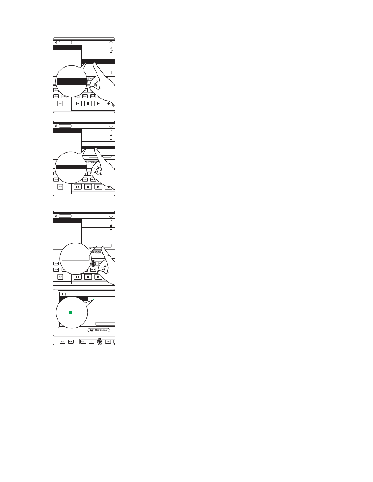
5. Select the mixer you’d like to use to control the preamps on your NSB stage box.
By default, this is set to “All,” enabling any StudioLive Series III mixer on the AVB
network to control the preamps on your stage box.
Power User Tip: Because your NSB stage box inputs are most likely routed to
multiple sources on your network, PreSonus highly recommends designating one
mixer to control the NSB preamps. Please review your NSB-series Owners Manual
for information on preamp permissions and gain compensation.
6. Select the AVB Output Sends you’d like returned to the physical outputs on your
NSB stage box. Because the AVB streams are routed in banks of 8, you can only
source these outputs from one mixer on the network.
Note: As previously mentioned, this is also the clocksource for your NSB-series stage
box. You must assign an output stream from your mixer to your NSB-series stage box
so that it is clocked properly over the network. If you do not assign an output stream
from your mixer, your networked stage box will not be properly synced and you will
hear audio artifacts.
7. Press the Apply button when finished.
Power User Tip: Once send streams from your mixer have been successfully patched,
you will see a green status indicator next to your NSB stage box in the setup screen.
FX C FX D
FX A FX B
AVB Inputs
Stagebox Setup
Preamp Permissions: All
Name: NSB 16.8
Output Stream: None
Apply
i
NSB 16.8
StudioLive 16
All
StudioLive 16
FX C FX D
FX A FX B
AVB Inputs
Stagebox Setup
Preamp Permissions: All
Name: NSB 16.8
Output Stream: None
Apply
i
NSB 16.8
StudioLive 16: Send 41-48
StudioLive 16: Send 33-40
StudioLive 16: Send 49-56
StudioLive 16: Send 41-48
FX C FX D
FX A FX B
AVB Inputs
Stagebox Setup
Preamp Permissions: All
Name: NSB 16.8
Output Stream: StudioLive 16: Send 41-48
Apply
i
NSB 16.8
Apply
FX A FX B
AVB Inputs
Stagebox Setup
Preamp Permissions: All
Name: NSB 16.8
Output Stream: StudioLive 16: Send 41-48
Apply
NSB 16.8
Name: NSB 16.8
Page 31
28
4 Configuring Your AVB Network
4.2 NSB-series Stage Box with a StudioLive Series III Console Mixer
StudioLive™ Series III
AVB Networking Guide
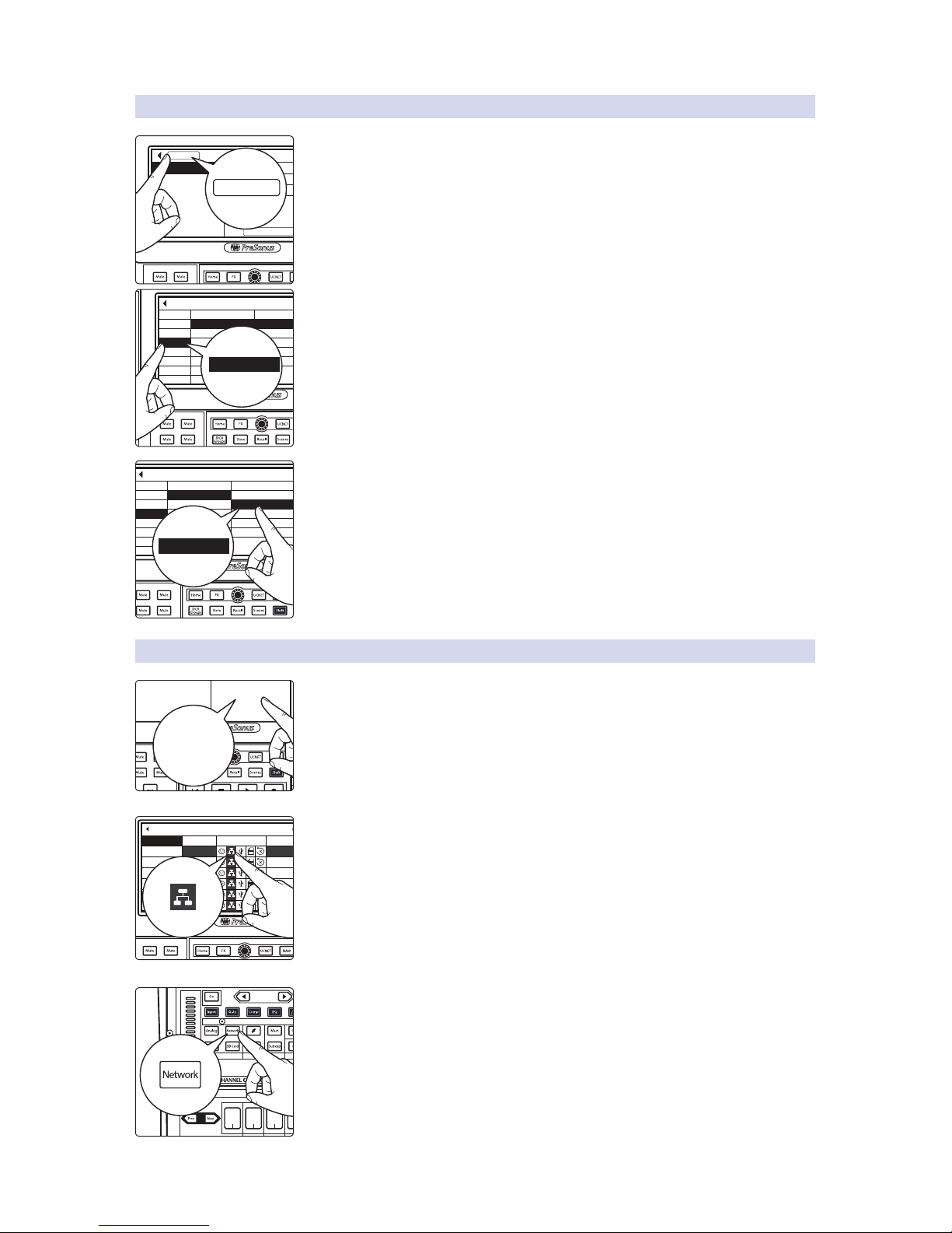
4.2.2. Step 2: Routing Stage Box Inputs to Mixer
1. Press the AVB Inputs button.
2. Select the desired mixer input stream from the Input Streams list.
3. Select the desired NSB AVB output stream from the Available Stream list to patch
the NSB inputs to selected channels on your mixer.
Note: NSB stage boxes have two sets of streams: one with Gain Compensation and
one without. Please review your NSB-series Owners Manual for more information on
Gain Compensation and when it is advantageous or even required.
4.2.3 Step 3: Engage Network Sources
1. Press Digital Patching from the Audio Routing menu.
2. Select Input Source and assign the Network source for the desired channels by
pressing the Network button next to each Input.
OR
Select each channel and press the Network button from the Input source section
in the Fat Channel.
Your NSB-series stage box is now ready to use!
FX A FX B
AVB Inputs
Stagebox Setup
Preamp Permissions: All
Name: NSB 16.8
Output Stream: StudioLive 16: Send 41-48
Apply
NSB 16.8
AVB Inputs
FX C FX D
FX A FX B
AVB Input Streams
Available StreamAssigned Stream
Input Streams
Input 1-8 None
NSB 16.8: Send 1-8
None
None
NSB 16.8: Send 9-16None
None
None
None
None
Input 9-16
Input 17-24
Input 25-32
Input 33-40
Input 41-48
Input 49-56
NSB 16.8: Send 1-8 (GC)
NSB 16.8: Send 9-16 (GC)
Input 17-24
FX C FX D
FX A FX B
AVB Input Streams
Available StreamAssigned Stream
Input Streams
Input 1-8 None
NSB 16.8: Send 1-8
None
None
NSB 16.8: Send 9-16None
None
None
None
None
Input 9-16
Input 17-24
Input 25-32
Input 33-40
Input 41-48
Input 49-56
NSB 16.8: Send 1-8 (GC)
NSB 16.8: Send 9-16 (GC)
NSB 16.8: Send 1-8
FX C FX D
FX A FX B
AVB Input Streams
Audio Routing
Stagebox Setup
Digital Patching
Earmix Setup
Digital Patching
FX A FX B
Input Source
Analog Outputs
Digital Patching
Input
AVB 18
AVB 19
AVB 20
AVB 21
AVB 22
Ch. 18
Ch. 19
Ch. 20
Ch. 21
Ch. 22
Assigned Source Available Source
AVB Outputs
USB Outputs
SD Card/AES
Reset Source
Master Reset
Ch. 17 AVB 17
i
Page
(Insert)
Input Mic/Line Assign
Channel
Stereo
Processor
OL
-2
-12
-24
-36
-48
-65
Level
Sb 1
Sub 1
Sb 2
Sub 2
Ax 3
Aux 3
Ax 4
Aux 4
Page 32
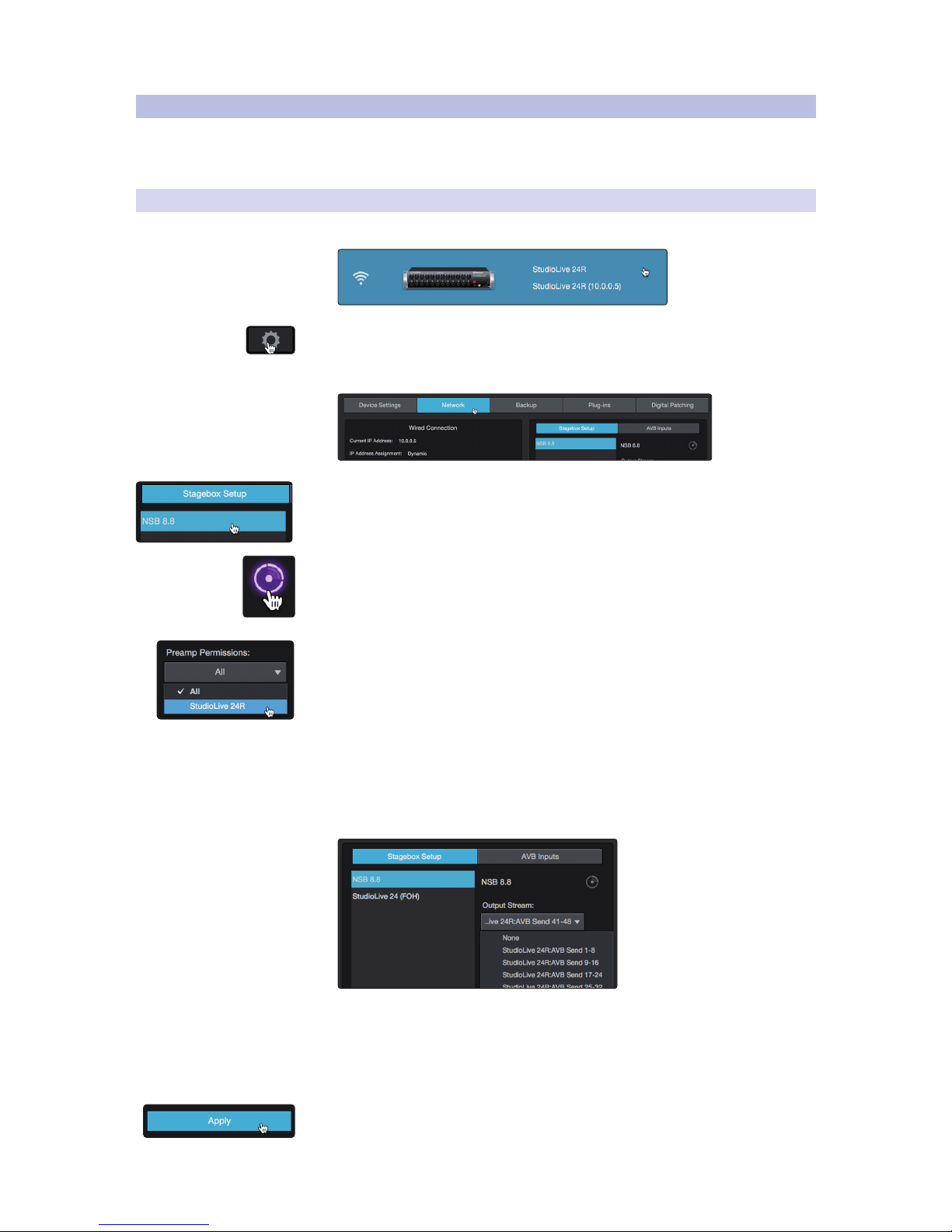
29
4 Configuring Your AVB Network
4.3 NSB-series Stage Box UC Surface Setup
StudioLive™ Series III
AVB Networking Guide
4.3 NSB-series Stage Box UC Surface Setup
As previously mentioned, NSB-series stage boxes can be configured and
routed from the touchscreen on the StudioLive Series III console mixers.
This can also be done from UC Surface for all StudioLive Series III mixers.
4.3.1 Step 1: Connect Your Stage Box to Your Mixer
1. Launch UC Surface and connect to your StudioLive Series III mixer.
2. Click or Tap on the Settings Gear.
3. Click or Tap on the Network tab.
4. In the Stagebox Setup area, select the NSB-series stage box from the list.
Power User Tip: In applications where you are using multiple NSB-series stage boxes
of the same model, you can press the Identify button. This will flash the Power
Network LED on the front of the selected NSB stage box from green to red, allowing
you to quickly locate your selection.
5. Select the mixer you’d like to use to control the preamps on your NSB stage box.
By default, this is set to “All,” enabling any StudioLive Series III mixer on the AVB
network to control the preamps on your stage box.
Power User Tip: Because your NSB stage box inputs are most likely routed to
multiple sources on your network, PreSonus highly recommends designating one
mixer to control the NSB preamps. For more information on preamp permissions
and gain compensation, please review the NSB-series Owners Manual.
6. Select the AVB Output Sends from the mixer that you’d like returned to the
physical outputs on your NSB stage box. Because the AVB streams are routed in
banks of 8, you can only source these outputs from one mixer on the network.
Note: As previously mentioned, this is also the clocksource for your NSB-series stage
box. You must assign an output stream from your mixer to your NSB-series stage box
so that it is clocked properly over the network. If you do not assign an output stream
from your mixer, your networked stage box will not be properly synced and you will
hear audio artifacts.
7. Press the Apply button when finished.
Page 33
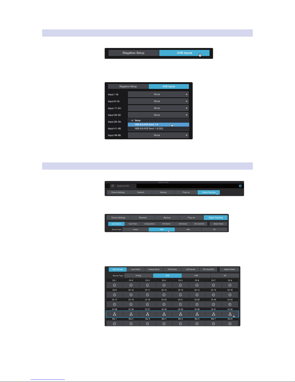
30
4 Configuring Your AVB Network
4.3 NSB-series Stage Box UC Surface Setup
StudioLive™ Series III
AVB Networking Guide
4.3.2 Step 2: Routing Stage Box Inputs to Your Mixer
1. Click on the AVB Inputs tab.
2. Next to desired inputs on your mixer, select the NSB AVB Send stream you
would like to use from the Available Stream drop-down menu. This will patch
the selected inputs on your NSB stage box to these channels on your mixer.
Note: NSB stage boxes have two sets of streams: one with Gain Compensation and
one without. Please review your NSB-series Owners Manual for more information
on Gain Compensation and when it is advantageous or even required.
4.3.3 Step 3: Engage Network Sources
1. Click or tap on the Digital Patching tab.
2. By default, the Input Source tab will be active. Select
AVB from the Source Type selection.
3. Click or tap on the source icon for channels on your StudioLive mixer
to change each channel’s source input to AVB. This will enable the
corresponding NSB stage box input to each channel. In the example
below, NSB Input 1 will be enabled on StudioLive 24R channel 25,
NSB Input 2 will be enabled on StudioLive 24R channel 26, etc.
Your NSB stage box is now ready to use!
Page 34
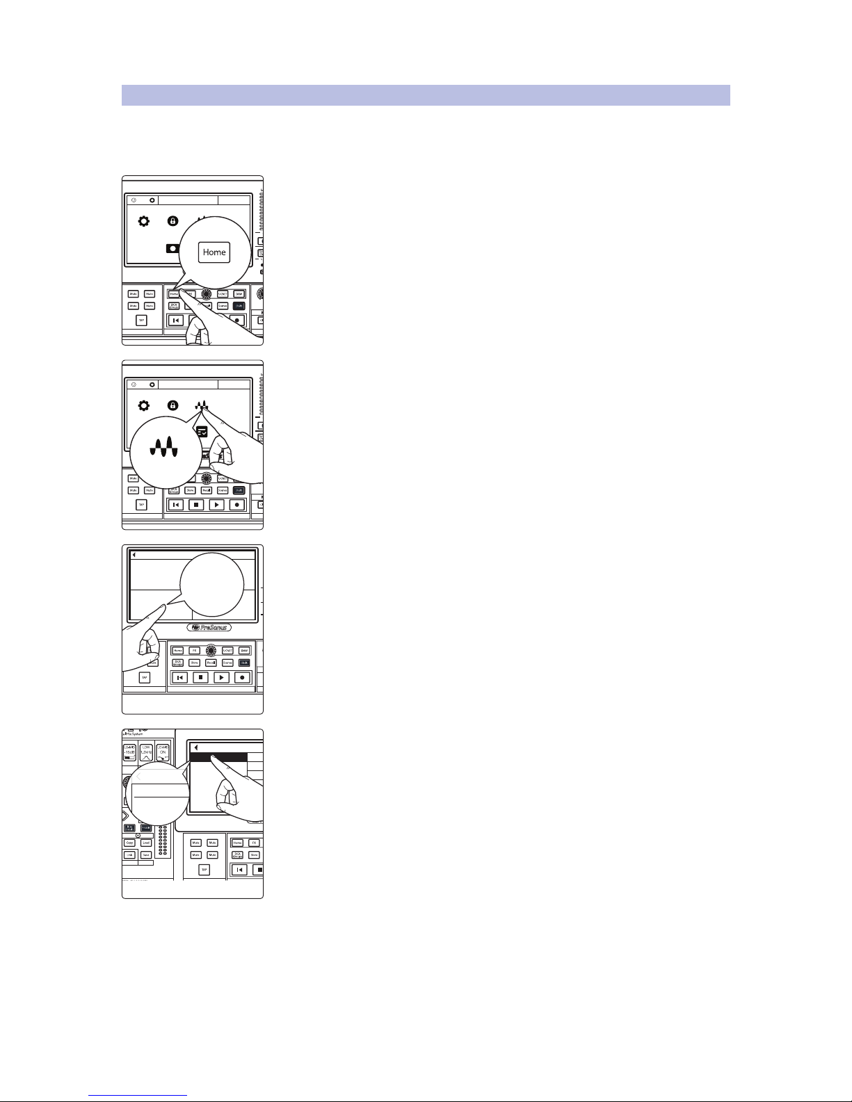
31
4 Configuring Your AVB Network
4.4 EarMix 16M with StudioLive Console Mixers
StudioLive™ Series III
AVB Networking Guide
4.4 EarMix 16M with StudioLive Console Mixers
EarMix 16M personal monitor mixers can be configured from the touchscreen
on any StudioLive Series III console mixer. It should be noted, however, that UC
Surface configuration is also available. Please review Section 4.5 for instructions.
1. Press the Home button on your StudioLive Series III mixer.
2. Press the Audio Routing icon on the Touchscreen.
3. Press the EarMix Setup button on the Touchscreen.
4. Select EarMix 16M from the list on the left.
MonitorFX C FX D
FX A FX B
EFFECTS MASTER MASTER CONTROL
1
Ch. 1
TB
System Global Lockout Audio Routing
UtilsCapture
Talkback Edit
Voume 0.5 dB
MonitorFX C FX D
FX A FX B
EFFECTS MASTER MASTER CONTROL
1
Ch. 1
TB
System Global Lockout Audio Routing
UtilsCapture
Talkback Edit
Voume 0.5 dB
Audio Routing
FX C FX D
FX A FX B
EFFECTS MASTER MASTER CONTROL
AVB Input Streams
Audio Routing
Stagebox Setup
Digital Patching
Earmix Setup
EarMix Setup
(Insert)
Stereo
Preset
Comp Gate
EQ / Dyn
FX C FX D
FX A FX B
-2
-12
-24
-36
-48
-65
EarMix Setup
Name: EarMix 16M
1-8 Send Source: AVB Send 41-48
9-16 Send Source: AVB Send 49-56
EarMix 16M
EarMix 16
EarMix 16M
Page 35
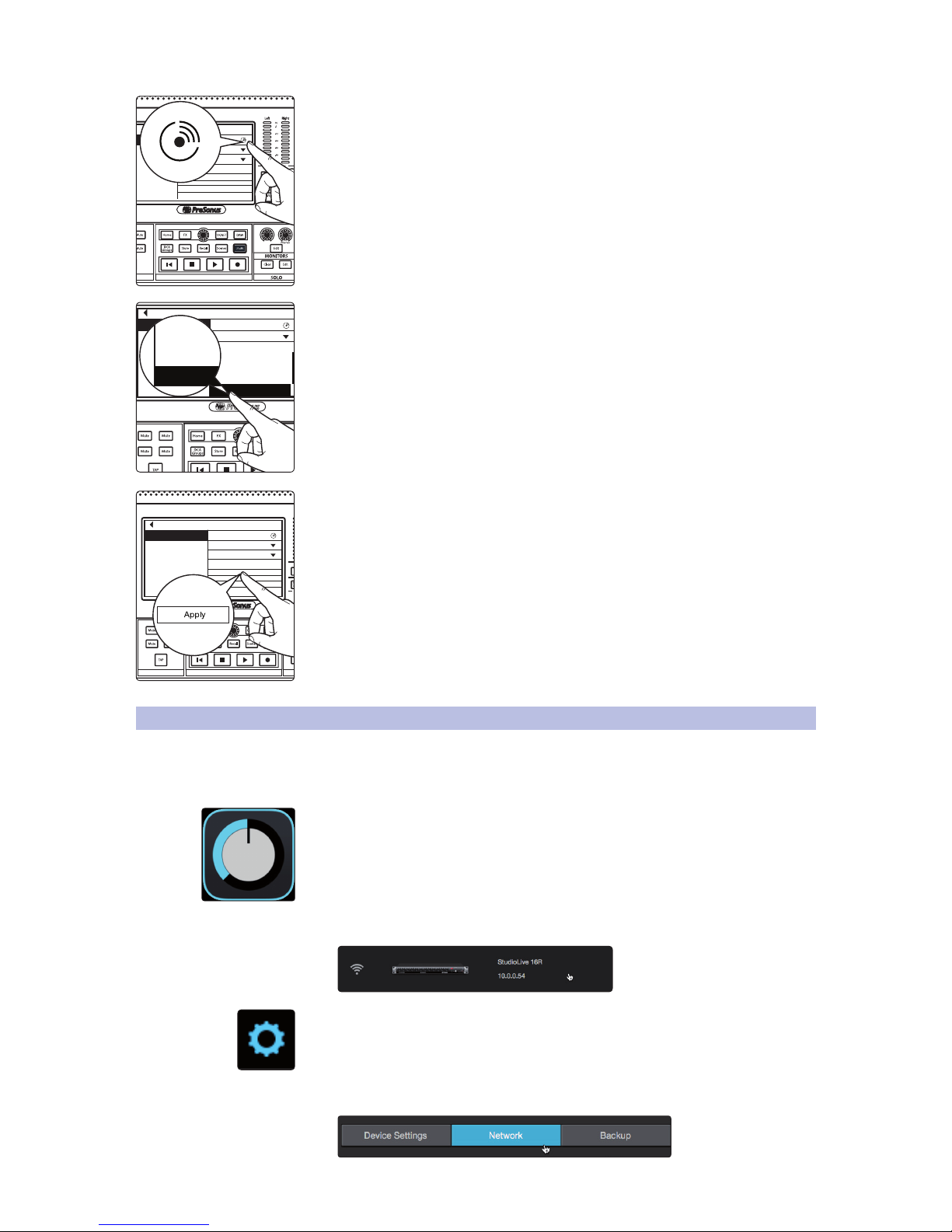
32
4 Configuring Your AVB Network
4.5 EarMix 16M Setup from UC Surface
StudioLive™ Series III
AVB Networking Guide
If you are unsure which EarMix 16M is which, press the Identify button. This will
flash all the Select buttons on the currently selected EarMix 16M.
5. Next, you will need to select the AVB Sends from your mixer to which you route
to your EarMix. By default, the last 16 AVB Inputs are patched from Flex Mixes
1-16.
6. Press apply to finish.
Power User Tip: If you are configuring multiple EarMix 16M Personal Monitor Mixers and
would like them to receive the same routing from the mixer, press the Apply All button.
This will apply the current AVB routings to every EarMix 16M currently on the AVB
network.
4.5 EarMix 16M Setup from UC Surface
As previously mentioned, EarMix 16M personal monitor mixers can be configured
and routed from the touchscreen on the StudioLive Series III console mixers.
This can also be done from UC Surface for all StudioLive Series III mixers.
1. Launch Universal Control.
2. Select your mixer from the device list.
3. Click or Tap on the Settings Gear.
4. Click or Tap on the Networking tab.
MonitorFX D
FX B
EarMix Setup
Name: EarMix 16M
Apply
Apply All
1-8 Send Source: AVB Send 41-48
9-16 Send Source: AVB Send 49-56
FX C FX D
FX A FX B
EarMix Setup
Name: EarMix 16M
Apply
Apply All
1-8 Send Source: AVB Send 41-48
9-16 Send Source: AVB Send 49-56
EarMix 16M
AVB Send 9-16
AVB Send 9-16
AVB Send 9-16
AVB Send 9-16
AVB Send 9-16
AVB Send 9-16
AVB Send 9-16
AVB Send 9-16
AVB Send 9-16
AVB Send 9-16
MonitorFX C FX D
FX A FX B
EFFECTS MASTER MASTER CONTROL
EarMix Setup
Name: EarMix 16M
Apply
Apply All
1-8 Send Source: AVB Send 41-48
9-16 Send Source: AVB Send 49-56
EarMix 16M
Page 36
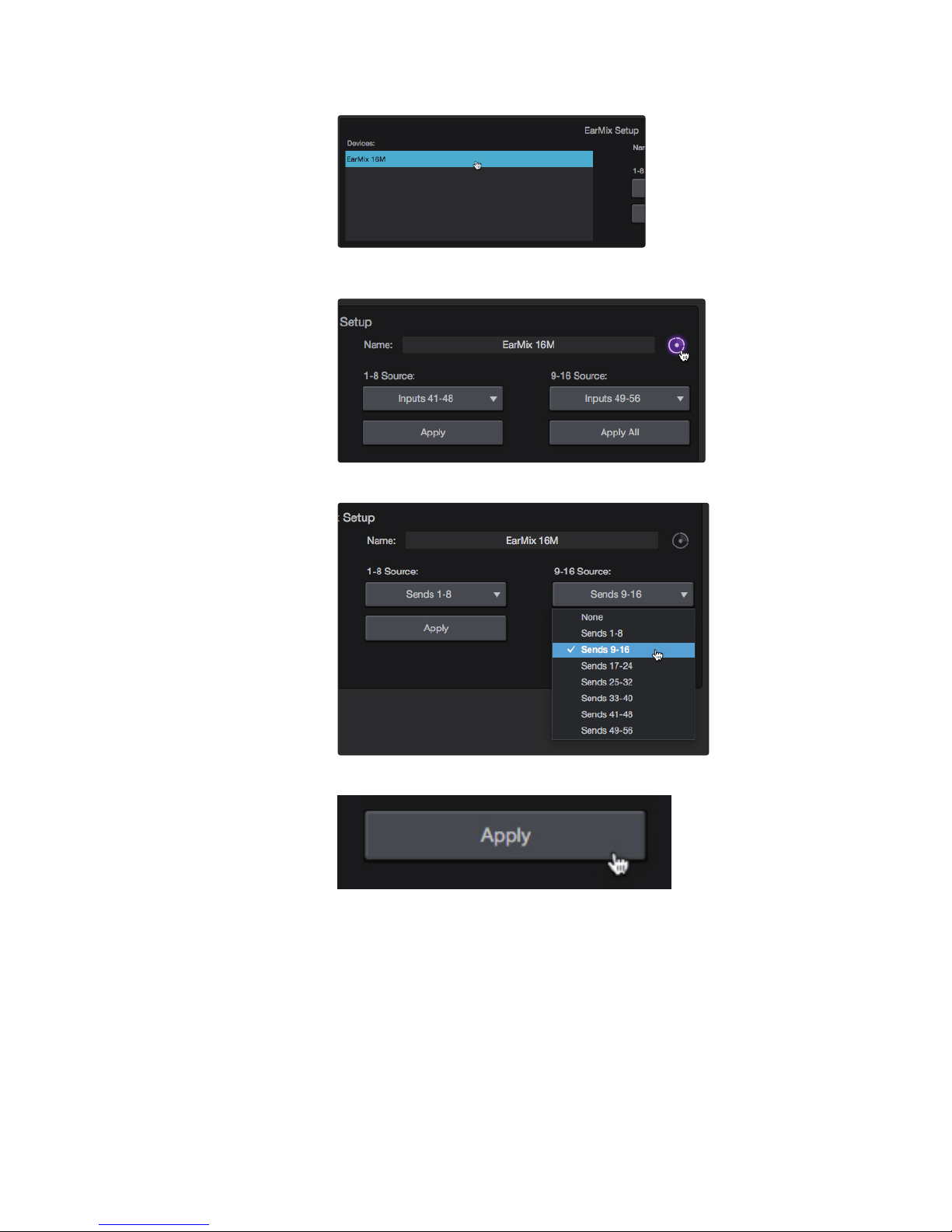
33
4 Configuring Your AVB Network
4.5 EarMix 16M Setup from UC Surface
StudioLive™ Series III
AVB Networking Guide
5. Select EarMix 16M in the device list.
If you are unsure which EarMix 16M is which, click or tap the Identify button.
This will flash the Select buttons on the currently selected EarMix 16M.
6. Select the desired StudioLive mixer AVB sends for Source Selection 1-8 and 9-16.
7. Press apply to finish.
Page 37
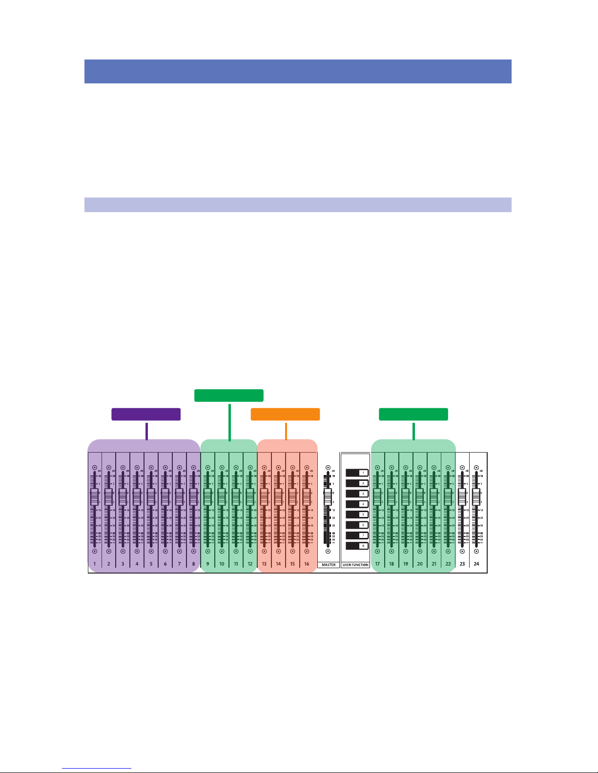
34
5 Large Network: Real-world Example
5.1 Example Network Overview
StudioLive™ Series III
AVB Networking Guide
5 Large Network: Real-world Example
This section provides detailed instructions on creating a large
network that combines all of the information covered in this guide.
These instructions can be altered and applied to other installations as
necessary and are meant to serve as an example configuration.
This guide will break down the example system as follows:
• AVB and Control Network Connections
• Audio Input Connections
• Audio Output Connections
5.1 Example Network Overview
Our example will consist of the following PreSonus products. It should be
noted that any PreSonus StudioLive Series III mixer can be used for any or
all of the applications described below. The exception being the StudioLive
16R. While the set-up instructions are the same, this mixer is not expandable
to 32 inputs, 16 Flex Mixes, and 4 subgroups like the rest of the family:
Front-of-House Console
A StudioLive 24 console mixer is used for Front-of-House. This compact
console is a full 32-channel mixer with 16 Flex Mixes and 4 Subgroups
that can be routed to and from the network. While the onboard analog
I/O is limited, this mixer can be expanded using any StudioLive Series III
mixer, NSB-series stage box, or EarMix 16M personal monitor mixer.
The StudioLive 24 at Front-of-House in our example
will receive its channel sources as follows:
NSB 8.8
NSB 16.8
StudioLive 24R
NSB 16.8
Page 38
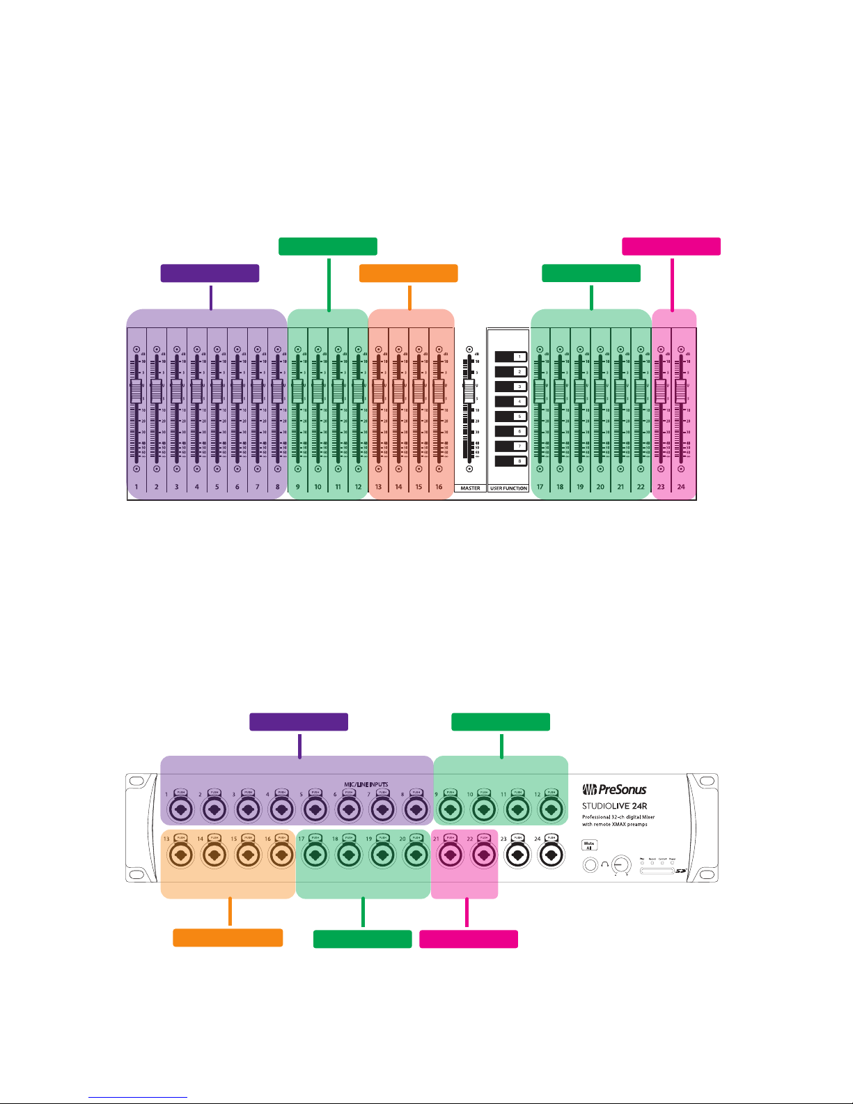
35
5 Large Network: Real-world Example
5.1 Example Network Overview
StudioLive™ Series III
AVB Networking Guide
Broadcast Console
A second StudioLive 24 is shown in a remote broadcast location on the network.
Because this is an independent stand-alone mixer, it can source its input and
output streams locally or from anywhere on the network and then mix them
down for a live stream on a computer connected via USB, or use any of the
analog mix outputs or the AES output to feed an external broadcast system.
The StudioLive 24 at Broadcast e in our example will
receive its channel sources as follows:
Monitor Mixer
A StudioLive 24R will be used in Monitor Mix mode allowing us to easily mirror
the main mix while retaining the ability to create monitor mixes for the local
Flex Mixes to feed floor wedges. Because the StudioLive 24R is controlled
exclusively by UC Surface, the monitor mixes can be controlled anywhere
in the venue, even from stage or Front-of-House, if necessary. For more
information on UC Surface, please review the QMix-UC Reference Manual.
The StudioLive 24R at Monitor position in our example
will receive its channel sources as follows:
NSB 8.8
NSB 16.8 StudioLive 24 (FOH)
StudioLive 24R
NSB 16.8
NSB 8.8
NSB 16.8
StudioLive 24 (FOH)
StudioLive 24R (local)
NSB 16.8
Page 39
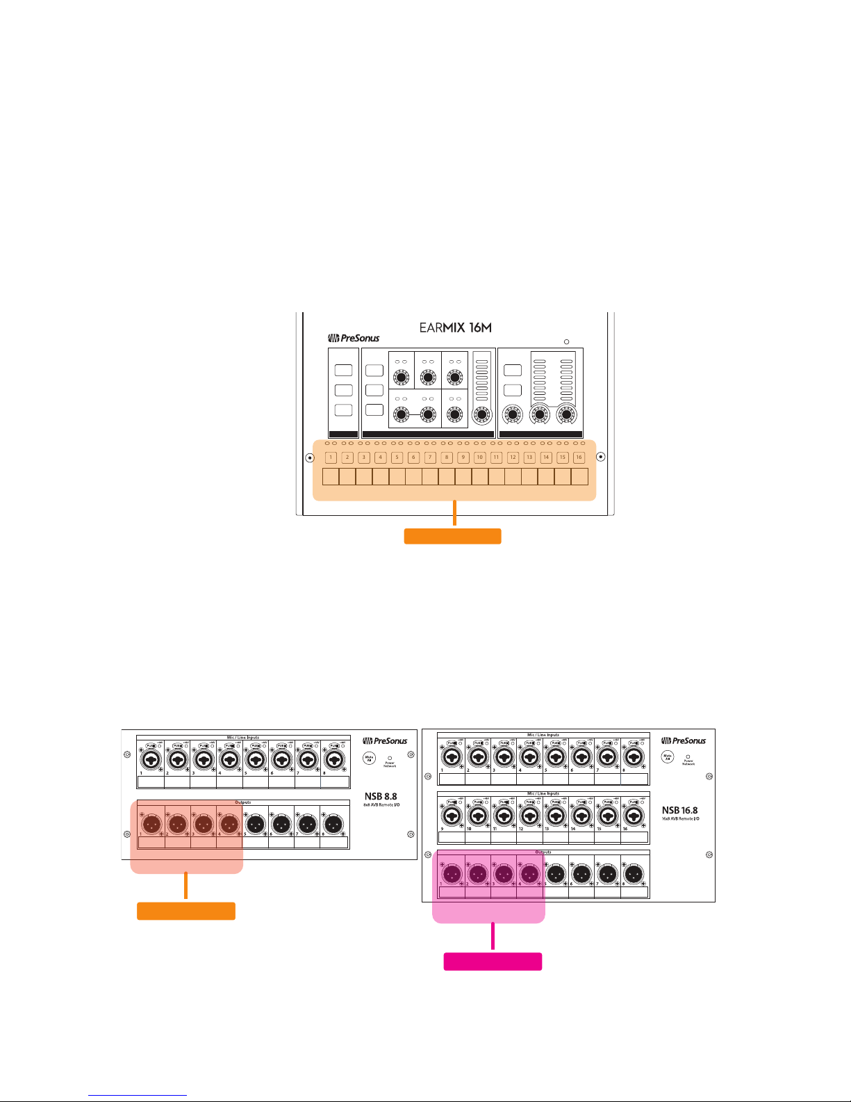
36
5 Large Network: Real-world Example
5.1 Example Network Overview
StudioLive™ Series III
AVB Networking Guide
Personal Monitoring
Personal monitoring will be available both from four EarMix 16M personal
monitor mixers as well as from QMix-UC. Each EarMix 16M is a 16-channel
digital mixer that receives audio inputs exclusively over AVB to be mixed
locally from the EarMix control surface. EarMix 16M personal mixers
are equipped with a high-voltage headphone amplifier and stereo line
outputs to feed either headphones or powered floor wedges.
By contrast, QMix-UC is an Android™ and iOS® app that remotely controls the Aux
Mixes on a StudioLive mixer. This is a great solution for musicians using wireless
in-ear system who desire simple, handheld control on their personal mobile device.
For more information on QMix UC, please review the QMix-UC Reference Manual.
Each of the four EarMix 16M personal monitor mixers in our
example will receive their channel sources as follows:
Stage Boxes
An NSB 8.8 and NSB 16.8 will both be added to the network to provide
two different locations on stage for analog connections to simplify
cable runs. The NSB 8.8 will be used exclusively for the drum kit. The
NSB 16.8 will provide input connections for the rest of the band.
In addition to providing analog input connections on stage, the outputs of the
two NSB-series stage boxes will receive their sources in our example as follows:
Treble
Pan
Limit
Mid Freq Mid Level
Bass
PhonesLine OutAux Input
L
R
OL
-6
-18
-40
Level
Network
SELECTED CHANNELGLOBAL MASTER
1 2 3 4 5 6 7 8 9 10 11 12 13 14 15 16
Recall
Link
Store
Group Mute
Solo
Mono
Select
StudioLive 24R
StudioLive 24R
StudioLive 24 (FOH)
Page 40

37
5 Large Network: Real-world Example
5.2 Network Connections
StudioLive™ Series III
AVB Networking Guide
Network Switches
Two PreSonus SW5E AVB network switches will be added to the network.
One switch will be used exclusively for the EarMix 16 Personal Monitor
mixers so that all four devices can be powered over Ethernet. This
system also utilized the network switch built into the NSB-series stage
boxes to facilitate greater connectivity with fewer components.
Recording System
A computer is connected over USB to the StudioLive 24 at
Broadcast position to record up to 40 sources. StudioLive Series
III mixers include both Capture and Studio One Artist.
Wireless Router
A wireless router will be added to provide a LAN control network for
devices running UC Surface and QMix-UC. Please visit www.presonus.
com for a list of recommended wireless routers. Configuration tutorials
are available at www.presonus.com/learn/technical-articles.
5.2 Network Connections
Before beginning any Network configuration, it is highly
recommended that you follow the following best practices:
• Draw It. Just like when you create a complex analog audio system,
when you begin creating an AVB network, we recommend creating a
diagram on paper, before you start connecting equipment. Not only
will this provide you with a map from which to work more efficiently,
it will also save you hours of cable tracing later should something go
wrong, because you’ll know where all the Ethernet cables are going.
• Label it. Sure you think you’ll remember that your Front-of-House console
is connected to AVB port 2 on your switch and port 5 of your LAN router,
but best to be safe and label the cables at both ends, just to be sure.
• Place it. Place your gear where it needs to be located before
you connect any cables, especially if you’re making your own.
This will save time when you’re running cables later because
you know you’ll be running them to the correct location.
• Stretch it. Always leave a little slack in your cable runs. Ethernet
cable is not like analog cable in that it is not subject to the signal
degradation that comes from long cable runs. This will provide
you with some flexibility and room to adjust in the future.
In the diagram that follows, each component is connected to the AVB
network utilizing a modified star topology with the NSB-series stage boxes
and StudioLive 24R attached using a daisy-chain topology. It should be noted
that this system leaves room for stage expansion because of the AVB Thru
ports available on each of the EarMix 16M personal monitor mixers. These
connections could be used for additional components that don’t require PoE.
A separate LAN network has been created to remote control the three mixers
using UC Surface and QMix-UC. It should be noted that any wireless device
connected to the wireless router and running UC Surface or QMix-UC can
be connected to any or all three mixers. Because of this, it is important to
manage your user permissions. For more information on User Permissions,
please review the UC Surface and QMix-UC Reference Manuals.
Page 41
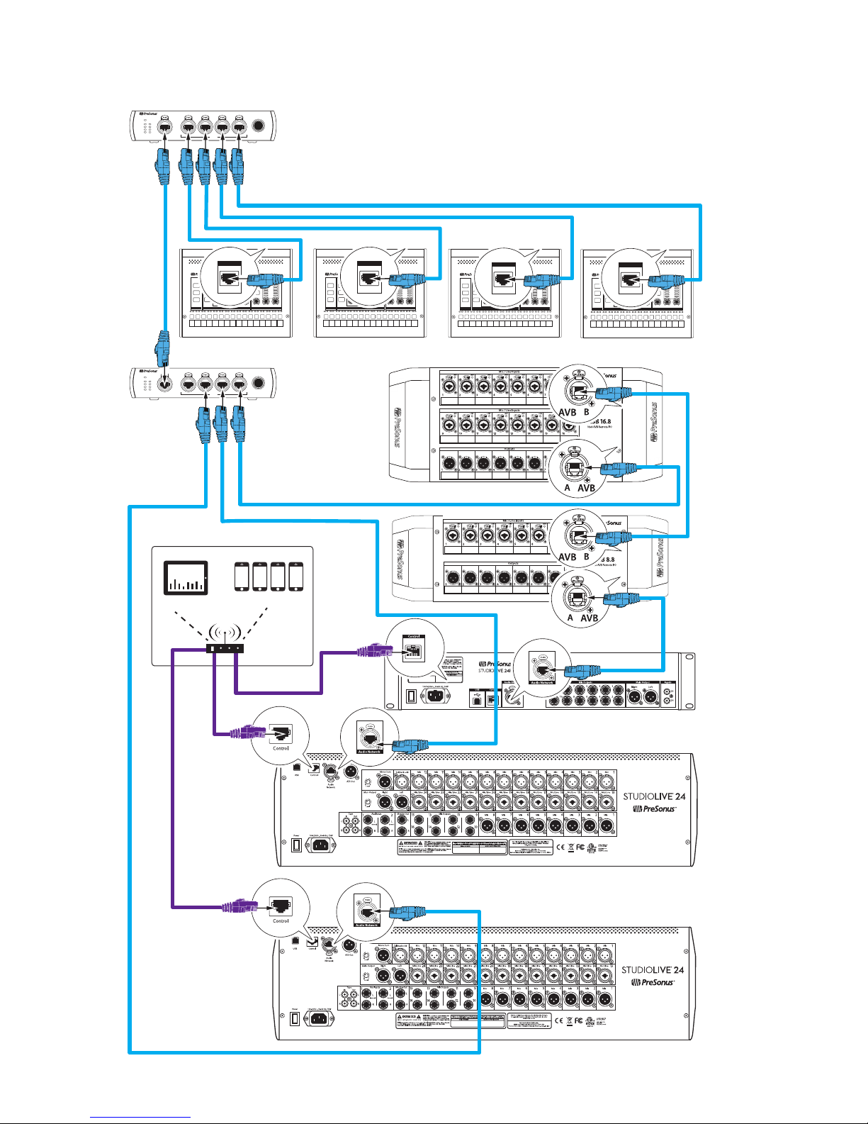
38
5 Large Network: Real-world Example
5.2 Network Connections
StudioLive™ Series III
AVB Networking Guide
Network Connection Diagram
Treble
Pan
Limit
Mid Freq Mid Level
Bass
PhonesLine OutAux Input
L
R
OL
-6
-18
-40
Level
Network
SELECTED CHANNELGLOBAL MASTER
1 2 3 4 5 6 7 8 9 10 11 12 13 14 15 16
Recall
Link
Store
Group Mute
Solo
Mono
Select
EarMix 16M Personal Monitor Mixer
Treble
Pan
Limit
Mid Freq Mid Level
Bass
PhonesLine OutAux Input
L
R
OL
-6
-18
-40
Level
Network
SELECTED CHANNELGLOBAL MASTER
1 2 3 4 5 6 7 8 9 10 11 12 13 14 15 16
Recall
Link
Store
Group Mute
Solo
Mono
Select
EarMix 16M Personal Monitor Mixer
Treble
Pan
Limit
Mid Freq Mid Level
Bass
PhonesLine OutAux Input
L
R
OL
-6
-18
-40
Level
Network
SELECTED CHANNELGLOBAL MASTER
1 2 3 4 5 6 7 8 9 10 11 12 13 14 15 16
Recall
Link
Store
Group Mute
Solo
Mono
Select
EarMix 16M Personal Monitor Mixer
Treble
Pan
Limit
Mid Freq Mid Level
Bass
PhonesLine OutAux Input
L
R
OL
-6
-18
-40
Level
Network
SELECTED CHANNELGLOBAL MASTER
1 2 3 4 5 6 7 8 9 10 11 12 13 14 15 16
Recall
Link
Store
Group Mute
Solo
Mono
Select
EarMix 16M Personal Monitor Mixer
NSB 16.8 Stage Box Stage Right
NSB 8.8 Stage Box Stage Right
StudioLive 24 (Broadcast)
StudioLive 24 (Front of House)
StudioLive 24R (Monitors)
AVB In
Link/ACT 1G
AVB In
Link/ACT 1G
AVB In
Link/ACT 1G
AVB In
Link/ACT 1G
Link PoE
Blue= PoE On
(Hold to toggle)
White= PoE O
1 2 3 4 5
SW5E
AVB SWITCH WITH PoE
PoE
Link PoE
1
2
3
4
5
Link PoE
Blue= PoE On
(Hold to toggle)
White= PoE O
1 2 3 4 5
SW5E
AVB SWITCH WITH PoE
PoE
Link PoE
1
2
3
4
5
iPads running
UC Surface
Mobile devices
running QMix-UC
wireless router
Page 42
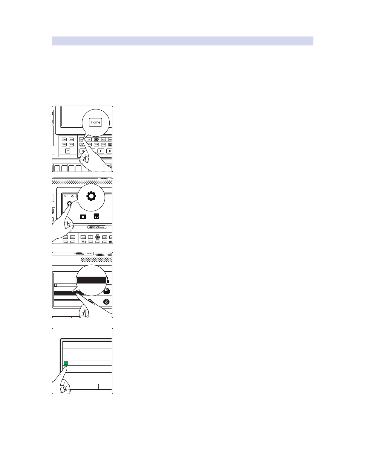
39
5 Large Network: Real-world Example
5.2 Network Connections
StudioLive™ Series III
AVB Networking Guide
5.2.1 Connecting Your Mixers
Connecting the three StudioLive Series III mixers to this network is relatively straightforward. All that needs to be done is to place the StudioLive 24R into Monitor Mixer
Mode and set the clock on the Broadcast mixer to the Network Stream, making the
mixer at Front-of-House the master clock for the system. Please note that clocking
for the StudioLive 24R is also coming from the mixer at Front-of-House. This setting
is handled automatically by the system when Monitor Mixer Mode is engaged.
Changing Network Clock
Changing the network clock can be done from the System menu. To begin, press
the Home button on your StudioLive 24 broadcast mixer.
From the Home menu, press System.
From the Network Clock menu, select Network Stream.
Note: The StudioLive 24 at Front-of-House must be connected to the
Network and powered on to properly distribute clock. Additionally, an
AVB stream must be connected to the Stream 1 input of the StudioLive
24 at broadcast as this is where network clock is derived.
The Clock Status indicator to the left of the selected clock source will illuminate
Green when your StudioLive mixer is properly synced.
FX C FX D
FX A FX B
EFFECTS MASTER MASTER CONTROL
Ch 7
7
FX C FX D
FX A FX B
-2
-12
-24
-36
-48
-65
1
Ch. 1
TB
System Global Lockout Audio Routing
UtilsCapture
Talkback Edit
Voume 0.5 dB
System
Permissions User Button Assgins
FirmwareFat Ch Load/Paste
Link Aux Mutes Bluetooth Reg.
Sample Rate:
48 kHz
Network Stream
Off
Med HighLow
HighLow
Network Clock:
Show Peak Hold:
LED:
Backlight:
Network Stream
Internal
Network Stream
Sample Rate:
48 kHz
Network Stream
Off
Med HighLow
Network Clock:
Show Peak Hold:
LED:
Backlight:
Page 43
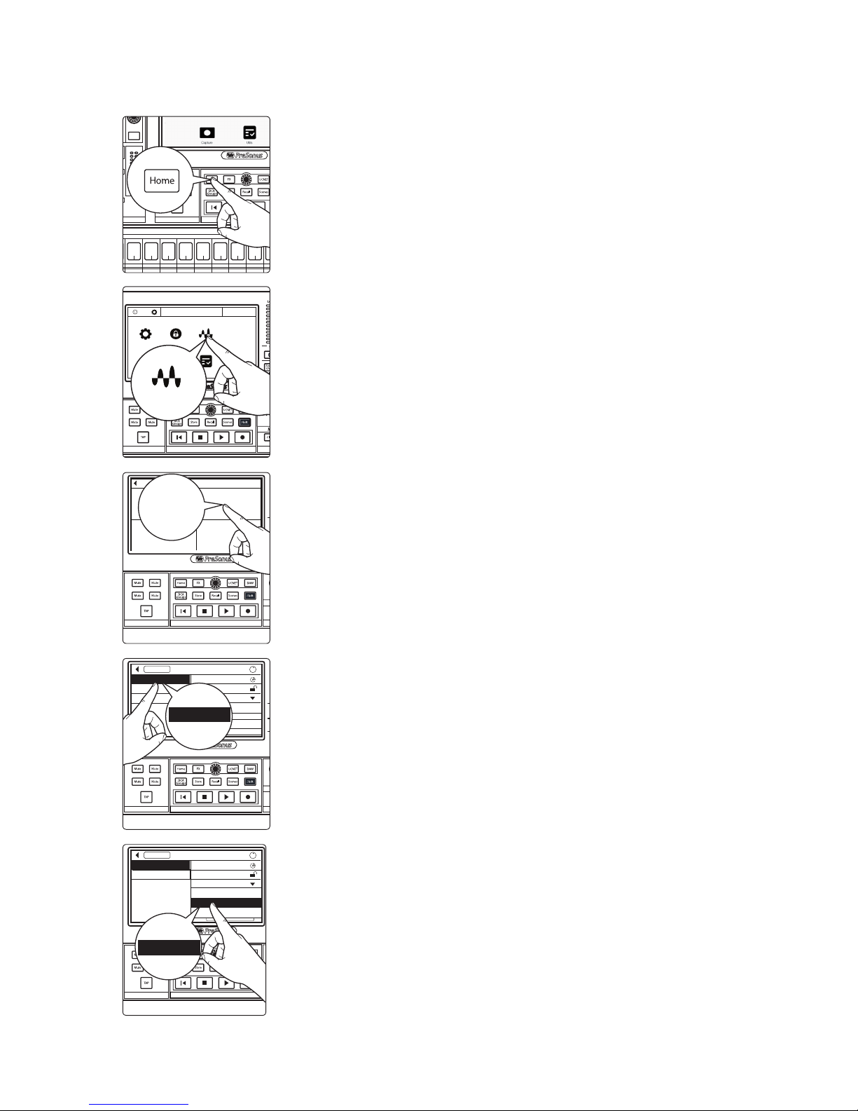
40
5 Large Network: Real-world Example
5.2 Network Connections
StudioLive™ Series III
AVB Networking Guide
Enabling Monitor Mixer Mode
1. Press the Home button on your StudioLive Series III console at Front-of-House.
2. Press Audio Routing on the Home Screen.
3. Press the Stagebox Setup button on the screen.
4. Select your rack mixer from the list at the left.
5. Select the Monitor Mixer Mode.
Comp Gate
FX C FX D
FX A FX B
EFFECTS MASTER MASTER CONTROL
-2
-12
-24
-36
-48
-65
Ch 66Ch 77Ch 88Ch 99Ch 1010Ch 1111Ch 1212Ch 1313Ch 14
14
MonitorFX C FX D
FX A FX B
EFFECTS MASTER MASTER CONTROL
1
Ch. 1
TB
System Global Lockout Audio Routing
UtilsCapture
Talkback Edit
Voume 0.5 dB
Audio Routing
FX C FX D
FX A FX B
EFFECTS MASTER MASTER CONTROL
AVB Input Streams
Audio Routing
Stagebox Setup
Digital Patching
Earmix Setup
Stagebox Setup
FX C FX D
FX A FX B
EFFECTS MASTER MASTER CONTROL
AVB Inputs
Stagebox Setup
Preamp Permissions: StudioLive 24
Name: StudioLive 24R
Mode: Monitor Mixer
Apply
Auto Config Routing
i
StudioLive 24R
NSB 8.8
NSB 16.8
StudioLive 24R
FX C FX D
FX A FX B
EFFECTS MASTER MASTER CONTROL
AVB Inputs
Stagebox Setup
Preamp Permissions: StudioLive 24
Name: StudioLive 24R
Mode: Monitor Mixer
Apply
i
StudioLive 24R
NSB 8.8
Monitor Mixer
Stand-alone
Stagebox
Monitor Mixer
Page 44
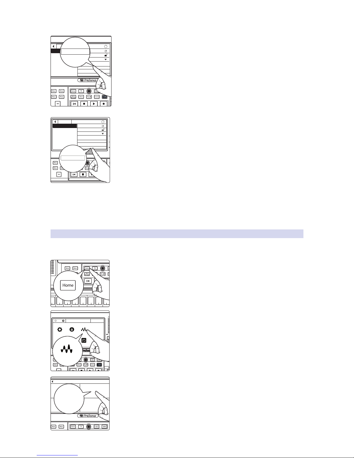
41
5 Large Network: Real-world Example
5.2 Network Connections
StudioLive™ Series III
AVB Networking Guide
StudioLive Series III mixers route channels in banks of 8. From the AVB Inputs page,
you can choose to auto-configure your routing as follows:
• Inputs 1-32 will be routed between the two networked mixers so that they
are available on both. The Main Mix will be routed from the console mixer
to the rack mixer, but the Flex Mixes will remain local to each mixer.
This is the configuration we will be using for our example.
6. Tap Apply to save the mode.
Power User Tip: Connecting to your mixer and selecting the mode can be one or two
steps. When Apply is pressed, both the selected mixer and the selected Stagebox Mode
are saved simultaneously.
Your mixers are now connected and synced to each other over the network.
Streams can be freely routed via the Digital Patching menu. More information
on Digital Patching can be found in the StudioLive Series III Owners Manual
and the UC Surface Reference Manual. The information in the rest of this
tutorial only covers network routing as it relates to our example.
5.2.2 Connect Your NSB-series Stage Boxes to Your Console Mixers
Complete the steps in this section for both the StudioLive 24
at Front-of-House and at the Broadcast position.
1. Press the Home button on the StudioLive 24.
2. Press the Audio Routing icon on the Touchscreen.
3. Press the Stagebox Setup button on the Touchscreen.
FX C FX D
FX A FX B
AVB Inputs
Stagebox Setup
Preamp Permissions: All
Name: StudioLive 24R
Mode: Stand-alone
Apply
Auto Config Routing
i
StudioLive 24R
Auto Config Routing
FX C FX D
FX A FX B
EFFECTS MASTER MASTER CONTROL
AVB Inputs
Stagebox Setup
Preamp Permissions: All
Name: StudioLive 24R
Mode: Stand-alone
Apply
Auto Config Routing
i
StudioLive 24R
Apply
FX C FX D
FX A FX B
EFFECTS MASTER MASTER CONTROL
-2
-12
-24
-36
-48
-65
Ch 66Ch 77Ch 88Ch 9
9
Ch 10
10
Ch 1111Ch 1212Ch 13
13
MonitorFX C FX D
FX A FX B
1
Ch. 1
TB
System Global Lockout Audio Routing
UtilsCapture
Talkback Edit
Voume 0.5 dB
Audio Routing
FX A FX B
AVB Input Streams
Audio Routing
Stagebox Setup
Digital Patching
Earmix Setup
Stagebox Setup
Page 45
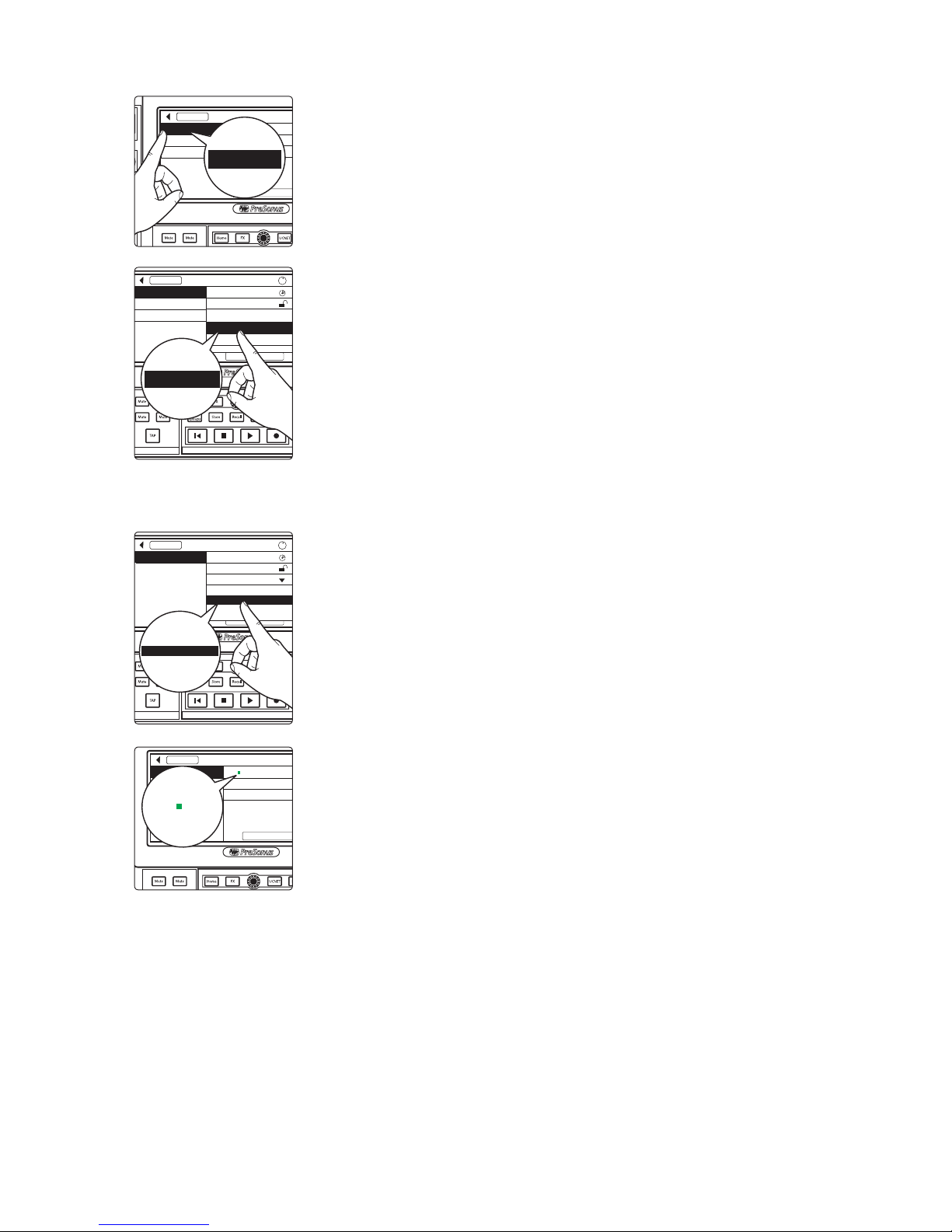
42
5 Large Network: Real-world Example
5.2 Network Connections
StudioLive™ Series III
AVB Networking Guide
4. Select the NSB16.8 from the list on the left.
5. In our example, we will be giving preamp permissions for all devices to the
StudioLive 24 at Front-of-House.
Power User Tip: Your StudioLive mixers can be given a custom name either from the
UCNET Screen (console mixers) or from UC Surface. For more information, please
review the StudioLive Series III Owners manual.
When you are done, repeat Steps 1-5 for the NSB 8.8.
Setting the Clock (NSB 16.8 only)
Select the StudioLive 24 (FOH) Sends 41-48 for the AVB Output Stream. This will
be the clocksource for the NSB 16.8 as well as route the appropriate AVB Sends
for our example. More information on AVB Output routing is covered in Section
5.4.
Power User Tip: Once send streams from your mixer have been successfully patched,
you will see a green status indicator next to your NSB stage box in the setup screen
indicating proper clocking.
FX A FX B
AVB Inputs
Stagebox Setup
Preamp Permissions: All
Name: NSB 16.8
Output Stream: None
Apply
NSB 16.8
NSB 8.8
StudioLive 24R
NSB 16.8
FX C FX D
FX A FX B
AVB Inputs
Stagebox Setup
Preamp Permissions: All
Name: NSB 16.8
Output Stream: None
Apply
i
NSB 16.8
NSB 8.8
StudioLive 24R
StudioLive 24 (FOH)
StudioLive 24 (Broadcast)
All
StudioLive 24 (FOH)
FX C FX D
FX A FX B
AVB Inputs
Stagebox Setup
Preamp Permissions: All
Name: NSB 16.8
Output Stream: None
Apply
i
NSB 16.8
StudioLive 24 (FOH): Send 41-48
StudioLive 24 (FOH): Send 33-40
StudioLive 24 (FOH): Send 49-56
StudioLive
24 (FOH)
: Send 41-48
FX A FX B
AVB Inputs
Stagebox Setup
Preamp Permissions: All
Name: NSB 16.8
Output Stream: StudioLive 16: Send 41-48
Apply
NSB 16.8
Name: NSB 16.8
Page 46
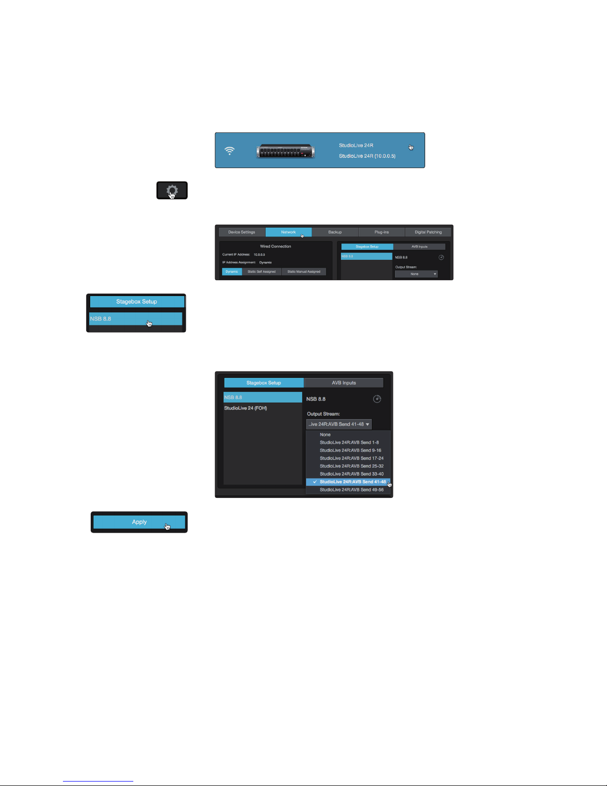
43
5 Large Network: Real-world Example
5.2 Network Connections
StudioLive™ Series III
AVB Networking Guide
Setting the Clock (NSB 8.8 only)
For the purposes of our example, the NSB 8.8 will be receiving Output
streams from the StudioLive 24R and so will clock to that device. This
will also patch the necessary Output Stream used in Section 5.4.
1. Launch UC Surface and connect to your StudioLive 24R.
2. Click or Tap on the Settings Gear.
3. Click or Tap on the Network tab.
4. In the Stagebox Setup area, select the NSB8.8 from the list.
5. Select StudioLive 24R: AVB Sends 41-48 from the
drop-down menu below ‘Output Stream.’
6. Press the Apply button when finished.
Page 47

44
5 Large Network: Real-world Example
5.3 Analog Input Connections
StudioLive™ Series III
AVB Networking Guide
5.3 Analog Input Connections
Once your network is connected, the next step is to connect your
analog devices. In our example is connected as follows:
Analog Input Instrument AVB Send
StudioLive 24 AVB
Input Streams
(FOH)
StudioLive 24 AVB
Input Streams
(Broadcast)
StudioLive 24R AVB
Input Streams
(Monitors)
NSB 8.8 In 1 Kick
NSB 8.8
Send 1-8 (GC)
Input 1-8 Input 1-8 Input 1-8
NSB 8.8 In 2 Snare
NSB 8.8
Send 1-8 (GC)
Input 1-8 Input 1-8 Input 1-8
NSB 8.8 In 3 High Hat
NSB 8.8
Send 1-8 (GC)
Input 1-8 Input 1-8 Input 1-8
NSB 8.8 In 4 Tom 1
NSB 8.8
Send 1-8 (GC)
Input 1-8 Input 1-8 Input 1-8
NSB 8.8 In 5 Tom 2
NSB 8.8
Send 1-8 (GC)
Input 1-8 Input 1-8 Input 1-8
NSB 8.8 In 6 Floor Tom
NSB 8.8
Send 1-8 (GC)
Input 1-8 Input 1-8 Input 1-8
NSB 8.8 In 7 Overhead Left
NSB 8.8
Send 1-8 (GC)
Input 1-8 Input 1-8 Input 1-8
NSB 8.8 In 8 Overhead Right
NSB 8.8
Send 1-8 (GC)
Input 1-8 Input 1-8 Input 1-8
NSB 16. 8 In 1 Bass D.I.
NSB 16.8
Send 1-8 (GC)
Input 9-16 Input 9-16 Input 9-16
NSB 16.8 In 2 Lead Guitar
NSB 16.8
Send 1-8 (GC)
Input 9-16 Input 9-16 Input 9-16
NSB 16.8 In 3 Rhythm Guitar
NSB 16.8
Send 1-8 (GC)
Input 9-16 Input 9-16 Input 9-16
NSB 16.8 In 4 Acoustic Guitar D.I.
NSB 16.8
Send 1-8 (GC)
Input 9-16 Input 9-16 Input 9-16
NSB 16.8 In 5 Backing Vox 1
NSB 16.8
Send 1-8 (GC)
Input 9-16 Input 9-16 Input 9-16
NSB 16.8 In 6 Backing Vox 2
NSB 16.8
Send 1-8 (GC)
Input 9-16 Input 9-16 Input 9-16
NSB 16.8 In 7 Keys 1 Left
NSB 16.8
Send 1-8 (GC)
Input 9-16 Input 9-16 Input 9-16
NSB 16.8 In 8 Keys 1 Right
NSB 16.8
Send 1-8 (GC)
Input 9-16 Input 9-16 Input 9-16
NSB 16.8 In 9 Keys 2 Left
NSB 16.8
Send 9-16 (GC)
Input 17-24 Input 17-24 Input 17-24
NSB 16.8 In 10 Keys 2 Right
NSB 16.8
Send 9-16 (GC)
Input 17-24 Input 17-24 Input 17-24
StudioLive 24R In 1 Wireless Mic 1
StudioLive 24R:
Send 1-8
Input 25-32 Input 25-32 Input 25-32
StudioLive 24R In 2 Wireless Mic 2
StudioLive 24R:
Send 1-8
Input 25-32 Input 25-32 Input 25-32
StudioLive 24R In 3 Wireless Mic 3
StudioLive 24R:
Send 1-8
Input 25-32 Input 25-32 Input 25-32
StudioLive 24R In 4 Wireless Mic 4
StudioLive 24R:
Send 1-8
Input 25-32 Input 25-32 Input 25-32
StudioLive 24 (FOH)
Aux 1 Left
DVD Left
StudioLive 24 (FOH):
Send 1-8
n/a Inputs 33-48 Inputs 33-48
StudioLive 24 (FOH)
Aux 1 Right
DVD Right
StudioLive 24 (FOH):
Send 1-8
n/a Inputs 33-48 Inputs 33-48
StudioLive 24 (FOH)
Talkback In
Talkback Mic
StudioLive 24 (FOH):
Send 1-8
n/a Inputs 33-48 Inputs 33-48
Page 48
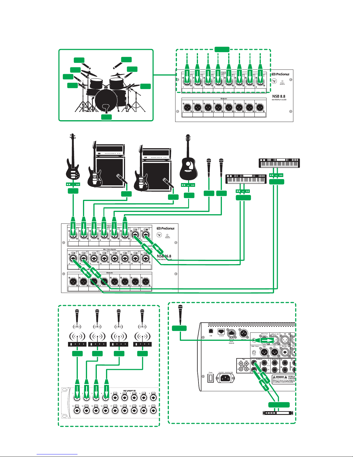
45
5 Large Network: Real-world Example
5.3 Analog Input Connections
StudioLive™ Series III
AVB Networking Guide
Audio Input Connection Diagram
lead
guitar amp
backup vocal mics
bass D.I.
acoustic guitar D.I.
In 1
In 2
In 3
In 4
In 7
In 8
In 5
In 6
drum kit
In 4
In 1
In 2
Ins 7-8
Ch 6In 5
In 3
keyboard/DI
keyboard/DI
rhythm
guitar amp
Ins 9-10
NSB 8.8 Stage Box Stage Right
NSB 16.8 Stage Box Stage Right
In 1 In 2 In 3 In 4
StudioLive 24R (Monitors)
Talkback
Aux In 1 L/R
dvd player
StudioLive 24 (Front of House)
Page 49
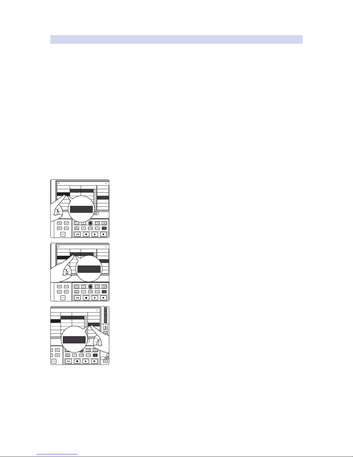
46
5 Large Network: Real-world Example
5.3 Analog Input Connections
StudioLive™ Series III
AVB Networking Guide
5.3.1 Routing AVB Sends to Your Console Mixers
For brevity, this section will only show the basic routing from the first input to
the NSB 8.8 to a console mixer. Channels from the NSB 16.8, the StudioLive 24R,
and the StudioLive 24 at Front-of-House are routed in the same manner. The
StudioLive 24 used for Broadcast should be configured exactly the same way
as the StudioLive 24 at Front-of-House. More information on NSB-series stage
box features and functions can be found in the NSB-series Owners Manual.
AVB Streams must be routed in banks of eight. The channels
within these streams are patched as follows:
• NSB-series. NSB-series inputs are patched one-to-one to their AVB Sends
(Input 1 is patched to AVB Send 1, Input 9 is patched to AVB Send 9, etc.).
• StudioLive Mixers. By default, mixer inputs are also patched one-
to-one to their AVB Sends. However, mixer inputs can be freely
routed to any destination via the Digital Patching menu.
Patching StudioLive 24 (FOH) Inputs to Their AVB Sends
Before we begin patching AVB Sends to the console mixer, we must first patch
the analog inputs we want available to the network from the StudioLive 24 at
Front-of-House to the AVB Sends we’d like to use (AVB Sends 1-8, in this case).
1. From the StudioLive 24 at Front-of-House, open the Digital Patching screen and
press the AVB Sends tab. For more information on Digital Patching, please
review the StudioLive Series III Owners Manual.
2. In the Inputs column, press AVB 1.
3. Select the Available Source column and use the value encoder to scroll to Aux In
1L.
Repeat Steps 1-3 to patch Aux 1R and the Talkback
In to AVB Sends 2 and 3 respectively.
Power User Tip: While our example doesn’t require this, it is important to note
that using Digital Patching in the manner described above can be done for
StudioLive rack mixers as well using the Digital Patching menu in UC Surface.
FX C FX D
FX A FX B
Input Source
Analog Outputs
Digital Patching
Input
Ch. 32
Analog 15
Aux In 2L
Aux In 2R
AVB 2
AVB 3
AVB 4
AVB 5
AVB 6
Ch. 2
Ch. 3
Ch. 4
Ch. 5
Ch. 6
Assigned Source Available Source
AVB Sends
USB Sends
SD Card/AES
Reset Sends
Master Reset
Ch. 31
Aux In 1R
i
AVB 1 AUX In 1L
Aux In 1L
AVB Sends
FX C FX D
FX A FX B
Input Source
Analog Outputs
Digital Patching
Input
Ch. 32
Analog 15
Aux In 2L
Aux In 2R
AVB 2
AVB 3
AVB 4
AVB 5
AVB 6
Ch. 2
Ch. 3
Ch. 4
Ch. 5
Ch. 6
Assigned Source Available Source
AVB Sends
USB Sends
SD Card/AES
Reset Sends
Master Reset
Ch. 31
Aux In 1R
i
AVB 1 AUX In 1L
Aux In 1L
AVB 1
MonitorFX C FX D
Digital Patching
Input
Ch. 32
Analog 15
Aux In 2L
Aux In 2R
AVB 2
AVB 3
AVB 4
AVB 5
AVB 6
Ch. 2
Ch. 3
Ch. 4
Ch. 5
Ch. 6
Assigned Source Available Source
Ch. 31
Aux In 1R
i
AVB 1 AUX In 1L
Aux In 1L
Aux In 1L
Page 50
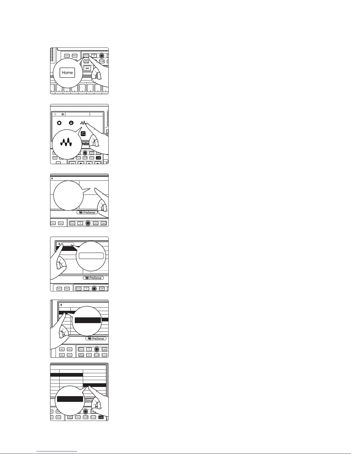
47
5 Large Network: Real-world Example
5.3 Analog Input Connections
StudioLive™ Series III
AVB Networking Guide
Patching AVB Sends
1. Press the Home button on your StudioLive Series III mixer.
2. Press the Audio Routing icon on the Touchscreen.
3. Press the Stagebox Setup button on the Touchscreen.
4. Press the AVB Inputs button.
5. Select Inputs 1-8 from the Input Streams list.
6. Select NSB 8.8: Send 1-8 (GC) from the Available Stream list to patch the first
eight NSB 8.8 Gain Compensated inputs to the first eight AVB input streams on
your mixer. For more information on Gain Compensation, please review the NSB-
series Owners manual.
Continue routing your AVB Streams to your mixer streams using
the table at the beginning of Section 5.3 as your guide.
FX C FX D
FX A FX B
EFFECTS MASTER MASTER CONTROL
-2
-12
-24
-36
-48
-65
Ch 66Ch 77Ch 88Ch 9
9
Ch 10
10
Ch 1111Ch 1212Ch 13
13
MonitorFX C FX D
FX A FX B
1
Ch. 1
TB
System Global Lockout Audio Routing
UtilsCapture
Talkback Edit
Voume 0.5 dB
Audio Routing
FX A FX B
AVB Input Streams
Audio Routing
Stagebox Setup
Digital Patching
Earmix Setup
Stagebox Setup
FX A FX B
AVB Inputs
Stagebox Setup
Preamp Permissions: All
Name: NSB 16.8
Output Stream: StudioLive 16: Send 41-48
Apply
NSB 16.8
NSB 8.8
StudioLive 24R
AVB Inputs
FX C FX D
FX A FX B
AVB Input Streams
Available StreamAssigned Stream
Input Streams
None
NSB 16.8: Send 9-16 (GC)
None
NSB 16.8: Send 9-16
NSB 8.8: Send 1-8None
None
None
None
None
Input 9-16
Input 17-24
Input 25-32
Input 33-40
Input 41-48
Input 49-56
NSB 8.8: Send 1-8 (GC)
StudioLive 24R: Send 1-8
StudioLive 24R: Send 9-16
StudioLive 24R: Sends 17-24
Input 1-8
Input 1-8
AVB Input Streams
Available StreamAssigned Stream
NSB 8.8: Send 1-8 (GC)
NSB 16.8: Send 9-16 (GC)
None
NSB 16.8: Send 9-16
NSB 8.8: Send 1-8None
None
None
None
None
NSB 8.8: Send 1-8 (GC)
StudioLive 24R: Send 1-8
StudioLive 24R: Send 9-16
StudioLive 24R: Sends 17-24
NSB 8.8: Send 1-8 (GC)
Page 51
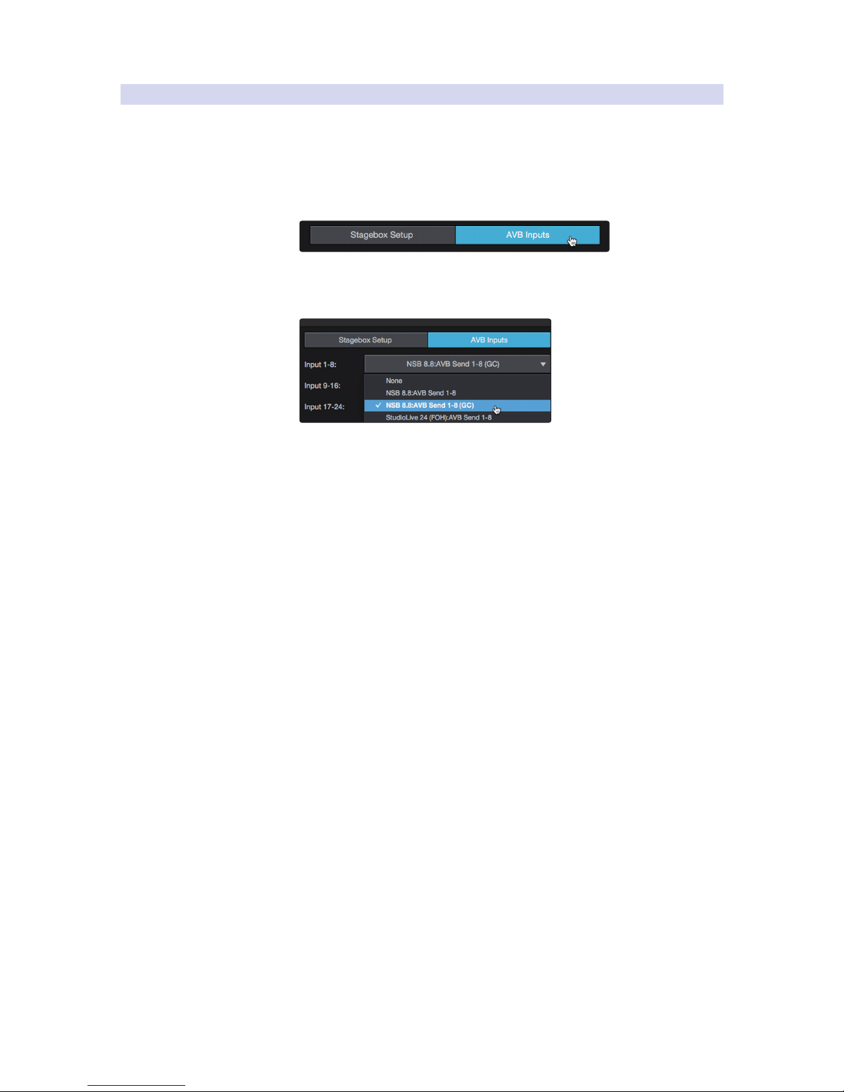
48
5 Large Network: Real-world Example
5.3 Analog Input Connections
StudioLive™ Series III
AVB Networking Guide
5.3.2 Routing the NSB-series Inputs to Your StudioLive 24R
For brevity, this section will only show the basic routing from the first
input to the NSB 8.8 to the StudioLive 24R. Channels from the NSB
16.8 as well as the StudioLive 24 (FOH) channels are routed in the
same manner. More information on StudioLive 24R as a monitor mixer,
please review the StudioLive Series III Stagebox Mode Addendum.
1. Click on the AVB Inputs tab.
2. Next to Inputs 1-8, select NSB 8.8: Send 1-8 (GC) from the Available
Stream drop-down menu. This will patch the eight inputs on
your NSB 8.8 to channels 1-8 on your StudioLive 24R.
Continue routing your AVB Streams to your mixer streams using
the table at the beginning of Section 5.3 as your guide.
Page 52

49
5 Large Network: Real-world Example
5.3 Analog Input Connections
StudioLive™ Series III
AVB Networking Guide
5.3.3 Routing Audio to the Console Mixers
In our example, we will be routing the audio sources as follows. For simplicity,
we will be routing the audio sources the same on every mixer:
Mixer Channel Source Physical Input
Channel 1 Kick NSB 8.8 In 1
Channel 2 Snare NSB 8.8 In 2
Channel 3 High Hat NSB 8.8 In 3
Channel 4 Tom 1 NSB 8.8 In 4
Channel 5 Tom 2 NSB 8.8 In 5
Channel 6 Floor Tom NSB 8.8 In 6
Channel 7 Overhead Left NSB 8.8 In 7
Channel 8 Overhead Right NSB 8.8 In 8
Channel 9 Bass NSB 16.8 In 1
Channel 10 Lead Guitar NSB 16.8 In 2
Channel 11 Rhythm Guitar NSB 16.8 In 3
Channel 12 Acoustic Guitar NSB 16.8 In 4
Channel 13 Wireless Mic 1 (lead vocals) StudioLive 24R In 1
Channel 14 Wireless Mic 2 StudioLive 24R In 2
Channel 15 Wireless Mic 3 StudioLive 24R In 3
Channel 16 Wireless Mic 4 StudioLive 24R In 4
Channel 17 Backing Vocals 1 NSB 16.8 In 5
Channel 18 Backing Vocal 2 NSB 16.8 In 6
Channel 19 Keys 1 Left NSB 16.8 In 7
Channel 20 Keys 1 Right NSB 16.8 In 8
Channel 21 Keys 2 Left NSB 16.8 In 9
Channel 22 Key 2 Right NSB 16.8 In 10
Channel 23 DVD Left
StudioLive 24 (FOH)
Aux 1L
Channel 24 DVD Right
StudioLive 24 (FOH)
Aux 1R
Talkback Talkback
StudioLive 24 (FOH)
Talkback
Note: The DVD and Talkback will be routed to their default channels on the StudioLive 24
at Front-of-House. This will allow the FOH engineer to use their Talkback system as well
as simplify the routing.
Page 53
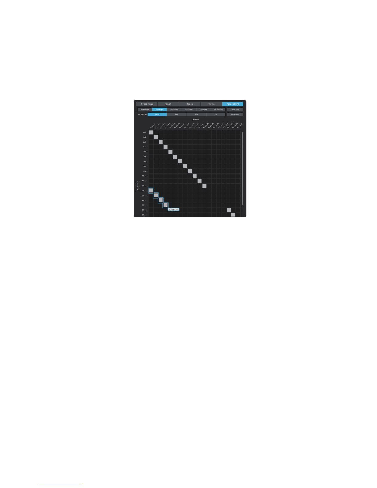
50
5 Large Network: Real-world Example
5.3 Analog Input Connections
StudioLive™ Series III
AVB Networking Guide
Rerouting Sources in UC Surface
In our example, we are using the default settings for most audio
routing. Because of this, we only need to reroute the four inputs on the
StudioLive 24R to alternative channels so that these sources on are the
same channels on every mixer. To do this, open the Digital Patching
menu in UC Surface and navigate to the Input Patch screen.
From the Input Patch tab, select Analog to view your Analog sources
and patch Inputs 1-4 to Channels 13-16 using the routing matrix.
Page 54
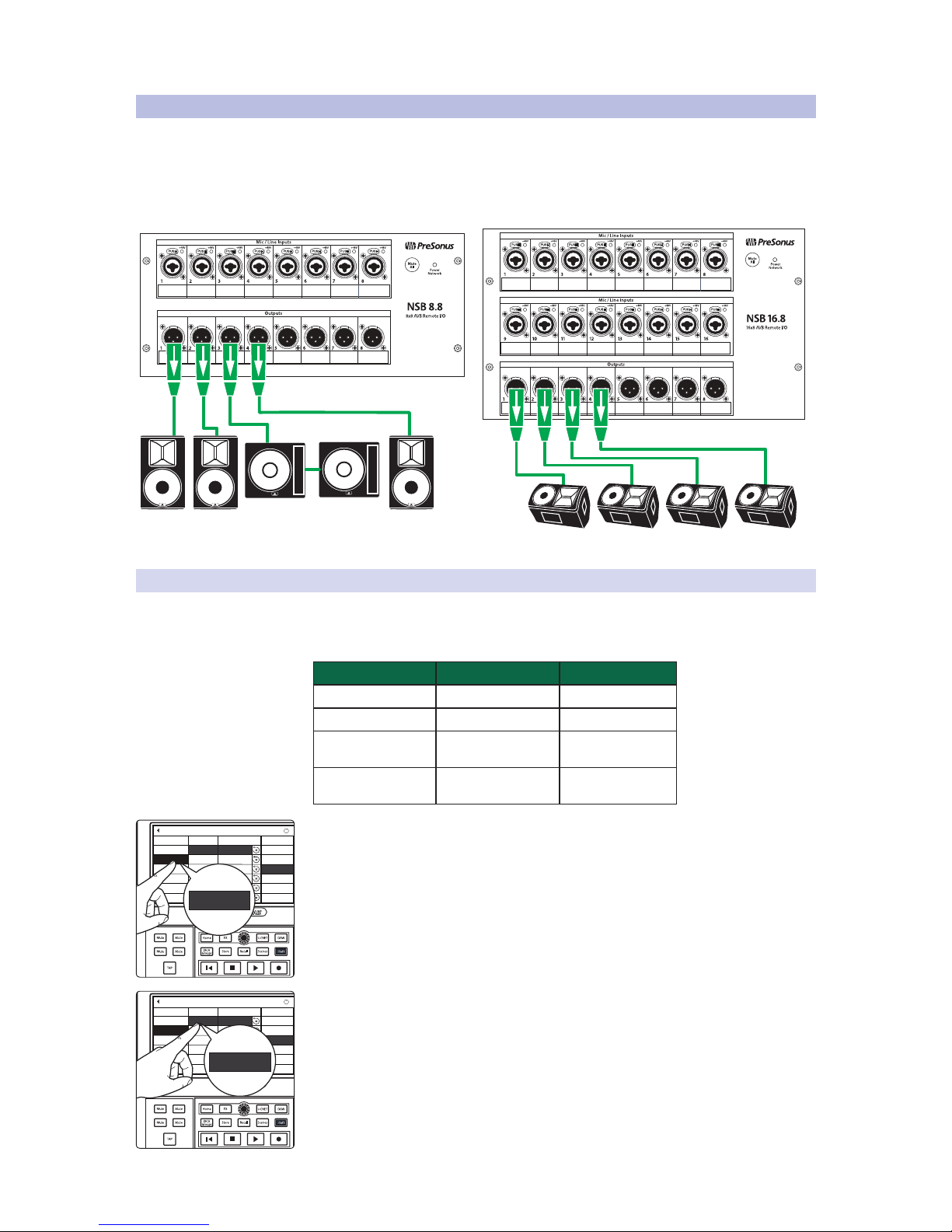
51
5 Large Network: Real-world Example
5.4 Analog Output Connections
StudioLive™ Series III
AVB Networking Guide
5.4 Analog Output Connections
For simplicity, the diagram below only shows the outputs that are being
sourced from the network. Obviously, in a system as complex as the one
used in this example, other local outputs would be put to use.
The floor wedges in our example are used as backup systems for the four
EarMix 16M and are being fed independent mixes from the StudioLive 24R.
NSB 16.8 Stage Box Stage Right
Sub Matrix
Mains
(Left)
Mains
(Right)
Front Fill
Floor
Monitor 1
Floor
Monitor 2
Floor
Monitor 3
Floor
Monitor 4
5.4.1 Routing the Main Outputs
In Section 5.2.2, we routed AVB Sends 1-8 from the StudioLive 24 at
Front-of-House to the NSB 16.8 on stage. In this section, we will be
routing the appropriate mixes to each AVB Send as follows:
Mix AVB Send NSB 16.8 Output
Main Mix Left AVB Send 41 NSB 16.8 Out 1
Main Mix Right AVB Send 42 NSB 16.8 Out 2
Subgroup Matrix Mix
(Subgroup A)
AVB Send 43 NSB 16.8 Out 3
Front Fill
(FlexMix 1)
AVB Send 44 NSB 16.8 Out 4
1. From the StudioLive 24 at Front-of-House, open the Digital Patching screen and
press the AVB Sends tab. For more information on Digital Patching, please
review the StudioLive Series III Owners Manual.
2. In the Inputs column, press AVB 41.
FX C FX D
FX A FX B
Input Source
Analog Outputs
Digital Patching
Input
Ch. 32
Analog 15
Aux In 2L
Aux In 2R
AVB 2
AVB 3
AVB 4
AVB 5
AVB 6
Ch. 2
Ch. 3
Ch. 4
Ch. 5
Ch. 6
Assigned Source Available Source
AVB Sends
USB Sends
SD Card/AES
Reset Sends
Master Reset
Ch. 31
Aux In 1R
i
AVB 1 AUX In 1L
Aux In 1L
AVB Sends
FX C FX D
FX A FX B
Input Source
Analog Outputs
Digital Patching
Input
Sub D
Analog 15
Solo L
Solo R
AVB 42
AVB 43
AVB 44
AVB 45
AVB 46
Mix 2
Mix 3
Mix 4
Mix 5
Mix 6
Assigned Source Available Source
AVB Sends
USB Sends
SD Card/AES
Reset Sends
Master Reset
Sub C
Main R
i
AVB 41 Main L
Main L
AVB 41
Page 55
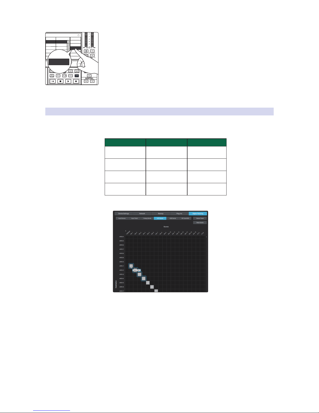
52
5 Large Network: Real-world Example
5.4 Analog Output Connections
StudioLive™ Series III
AVB Networking Guide
3. Select the Available Source column and use the value encoder to scroll to
Main L.
Repeat Steps 1-3 to patch Main R, Sub A and FlexMix 1 to AVB Sends 42-44
respectively.
5.4.2 Routing Monitor Mixes
In Section 5.2.3, we routed AVB Sends 1-8 from the StudioLive
24R to the NSB 8.8 on stage. In this section, we will be routing
the appropriate mixes to each AVB Send as follows:
Mix AVB Send NSB 8.8 Output
Monitor Mix 1
(FlexMix 1)
AVB Send 41 NSB 8.8 Out 1
Monitor Mix 2
(FlexMix 2)
AVB Send 42 NSB 8.8 Out 2
Monitor Mix 3
(FlexMix 3)
AVB Send 43 NSB 8.8 Out 3
Monitor Mix 4
(FlexMix 4)
AVB Send 44 NSB 8.8 Out 4
No additional set-up is required. By default, FlexMixes
1-4 are routed to AVB Sends 41-44.
Monitor
Digital Patching
Input
Sub D
Analog 15
Solo L
Solo R
AVB 42
AVB 43
AVB 44
AVB 45
AVB 46
Mix 2
Mix 3
Mix 4
Mix 5
Mix 6
Assigned Source Available Source
Sub C
Main R
i
AVB 41 Main L
Main L
Main L
Page 56
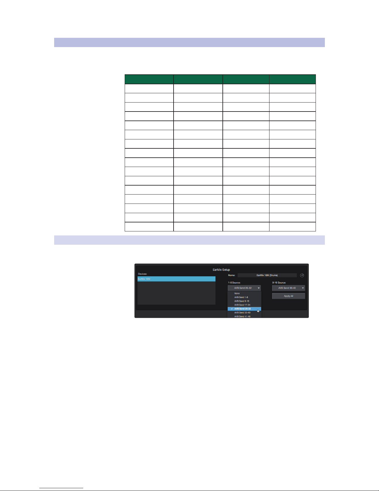
53
5 Large Network: Real-world Example
5.5 EarMix Setup
StudioLive™ Series III
AVB Networking Guide
5.5 EarMix Setup
In our example, all channels and mixes for all four EarMix 16M personal
monitor mixers will be routed from the StudioLive 24R. We will be
summing down the 25 channels to 16 channels as follows:
EarMix 16M Channel Instrument StudioLive 24R Source AVB Sends
Channel 1 Drum Mix L Flex Mix 5 StudioLive 24R Send 25
Channel 2 Drum Mix R Flex Mix 6 StudioLive 24R Send 26
Channel 3 Bass Channel 9 StudioLive 24R Send 27
Channel 4 Lead Guitar Channel 10 StudioLive 24R Send 28
Channel 5 Rhythm Guitar Channel 11 StudioLive 24R Send 29
Channel 6 Acoustic Guitar Channel 12 StudioLive 24R Send 30
Channel 7 Wireless Mic 1 (lead vocals) Channel 13 StudioLive 24R Send 31
Channel 8 Wireless Mic 2 Channel 14 StudioLive 24R Send 32
Channel 9 Wireless Mic 3 Channel 15 StudioLive 24R Send 33
Channel 10 Wireless Mic 4 Channel 16 StudioLive 24R Send 34
Channel 11 Backing Vocals 1 Channel 17 StudioLive 24R Send 35
Channel 12 Backing Vocal 2 Channel 18 StudioLive 24R Send 36
Channel 13 Keys 1 Left Channel 19 StudioLive 24R Send 37
Channel 14 Keys 1 Right Channel 20 StudioLive 24R Send 38
Channel 15 Keys 2 Left Channel 21 StudioLive 24R Send 39
Channel 16 Key 2 Right Channel 22 StudioLive 24R Send 40
5.5.1 Routing AVB Streams to Your EarMix 16M
From the EarMix Setup screen in UC Surface, route AVB Send 25-32 to 1-8 Source
and AVB Send 33-40 to 9-16 Source for each EarMix 16M on the network.
Page 57
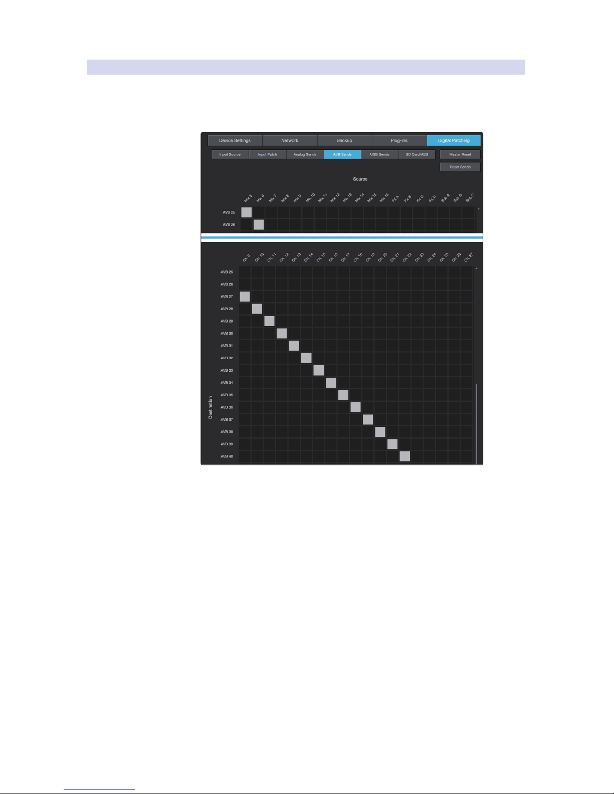
54
5 Large Network: Real-world Example
5.5 EarMix Setup
StudioLive™ Series III
AVB Networking Guide
5.5.2 Routing StudioLive 24R Sources to AVB Sends
The next step is to route the necessary channels and buses to the
appropriate AVB sends using the Digital Patching menu in UC Surface.
From the AVB Sends tab, you will route the input channels and mixes to their
respective AVB Sends as described in the table at the beginning of Section 5.5.
Page 58

© 2018 PreSonus Audio Electronics, Inc. All Rights Reserved. PreSonus, EarMix, and StudioLive are trademarks or registered trademarks of PreSonus Audio Electronics, Inc. Capture
and Studio One are trademarks or registered trademarks of PreSonus Software Ltd. Mac and Mac OS are registered trademarks of Apple, Inc., in the U.S. and other countries.
Windows is a registered trademark of Microsoft, Inc., in the U.S. and other countries. Other product names mentioned herein may be trademarks of their respective companies. All
specifications subject to change without notice...except the recipe, which is a classic.
Added bonus: PreSonus’ previously Top Secret recipe for…
Jambalaya
Ingredients:
• 5 lbs link andouille sausage
• 3 lbs boneless chicken
• 2 lbs ground beef
• 3 lbs onions (yellow or purple)
• 2 stalks of celery
• 1 lb bell peppers (green or red)
• 1 batch green onions
• 3 lbs rice
• Tony Chachere’s Cajun Seasoning
• 1 bottle chicken stock concentrate (or 3 cubes chicken bullion)
• 1 can Rotel tomatoes with chilies, diced (regular hot)
• Tabasco sauce
Cooking Instructions:
1. In a 16 qt. pot or larger, slice link sausage and pan-fry until brown.
2. Add ground beef and brown.
3. Do not remove from pot Add diced onions, celery, and bell peppers,
1 can Rotel Original diced tomatoes with chilies, 3 oz concentrate chicken stock,
½ teaspoon of Cajun seasoning, 1 teaspoon of Tabasco hot sauce
(or more…maybe lots more).
4. Cook until onions are translucent.
5. Add chicken and cook until it turns white.
6. Add diced green onions, 1 tsp. salt, ½ gallon water and bring to a boil.
7. Add rice and bring to a boil. Cook on high for 8 minutes, covered, stirring every 2 minutes
8. Cook covered on low for 10 minutes, stirring only once.
9. Turn off and let sit for 30 minutes.
10. Serve and enjoy!
Serves 20
Page 59
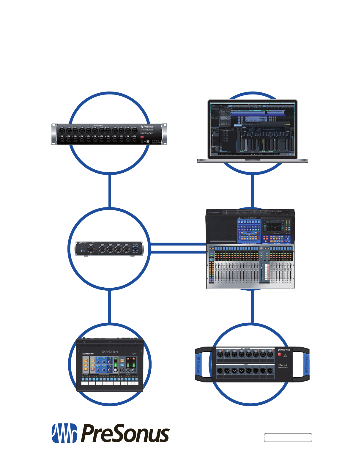
18011 Grand Bay Ct. • Baton Rouge,
Louisiana 70809 USA• 1-225-216-7887
www.presonus.com
Part# 70-22000106-A
®
StudioLive™ Series III
AVB Networking Guide
 Loading...