

PRESONUS MONITOR STATION - V1.0, MONITOR STATION User Manual
MONITOR
STATION
Studio Control Center
User’s Manual v1.0
© 2007, PreSonus Audio Electronics, Inc.
All Rights Reserved.

PRESONUS LIMITED WARRANTY
PreSonus Audio Electronics Inc. warrants this product to be free of defects in material and workmanship for a
period of one year from the date of original retail purchase. Th is warranty is enforceable only by the original
retail purchaser. To be protected by this warranty, the purchaser must complete and return the enclosed
warranty card within 14 days of purchase. During the warrant y period PreSonus shall, at its sole and absolute
option, either repair or replace, free of charge, any product that proves to be defective on inspection by
PreSonus or its authorized service representative. To obtain warranty service, the purchaser must first call or
write PreSonus at the address and telephone number printed belo w to obtain a Return Authorization Number
and instructions of where to return the unit for service. All inquiries must be accompanied by a description of
the problem. All authorized returns must be sent to the PreSonus repair facility postage prepaid, insured and
properly packaged. PreSonus reserves the right to update any unit returned for repair. PreSonus reserves the
right to change or improve the design of the product at any time without prior notice. This warranty does not
cover claims for damage due to abuse, neglect, alteration or attempted repair by unauthorized personnel, and is
limited to failures arising during normal use that are due to defects in material or workmanship in the product.
Any implied warranties, including implied warranties of merchantability and fitness for a particular purpose, are
limited in duration to the length of this limited warranty. Some states do not allow limitations on how long an
implied warranty lasts, so the above limitation may not apply to you. In no event will PreSonus be liable for
incidental, consequential or other damages resulting from the breach of any express or implied warranty,
including, among other things, damage to property, damage based on inconvenience or on loss of use of the
product, and, to the extent permitted by law, damages for personal injury. Some states do not allow the
exclusion of limitation of incidental or consequential damages, so the above limitation or exclusion may not
apply to you. This warranty gives you specific legal rights, and you may also have other rights, which vary from
state to state. This warranty only applies to products sold and used in the United States of America. For
warranty information in all other countries please refer to your local distributor.
PreSonus Audio Electronics, Inc.
7257 Florida Blvd.
Baton Rouge, LA 70806
www.PreSonus.com
© 2007, PreSonus Audio Electronics, Inc.
All Rights Reserved.

TABLE OF CONTENTS
1 OVERVIEW
1.1 Introduction ........................................................................................................................................... 2
1.2 Features ................................................................................................................................................ 3
1.3 What is in the Box ................................................................................................................................. 4
2 OPERATION
2.1 Quick Start ............................................................................................................................................ 5
2.1.1 Connect the power .......................................................................................................................... 5
2.1.2 Connect the input sources ............................................................................................................... 5
2.1.3 Calibrate the LED meter ................................................................................................................ 6
2.1.4 Calibrate the input sources ............................................................................................................. 6
2.1.5 Connect the speakers ...................................................................................................................... 7
2.1.6 Calibrate your speaker levels .......................................................................................................... 7
2.1.7 Calibrate the talkback microphone ................................................................................................ 10
2.1.8 Connect the Cue and Main outputs ................................................................................................. 10
2.2 Sample Hookup Diagram ..................................................................................................................... 11
2.3 Advanced Modes .................................................................................................................................. 12
2.3.1 Speaker Select Modes .................................................................................................................. 12
2.3.2 Main and Cue Source Modes ........................................................................................................ 12
2.3.3 Input LED Meter Modes .............................................................................................................. 13
2.3.4 Reset All Modes to Factory Default .............................................................................................. 13
3 CONTROLS & CONNECTIONS
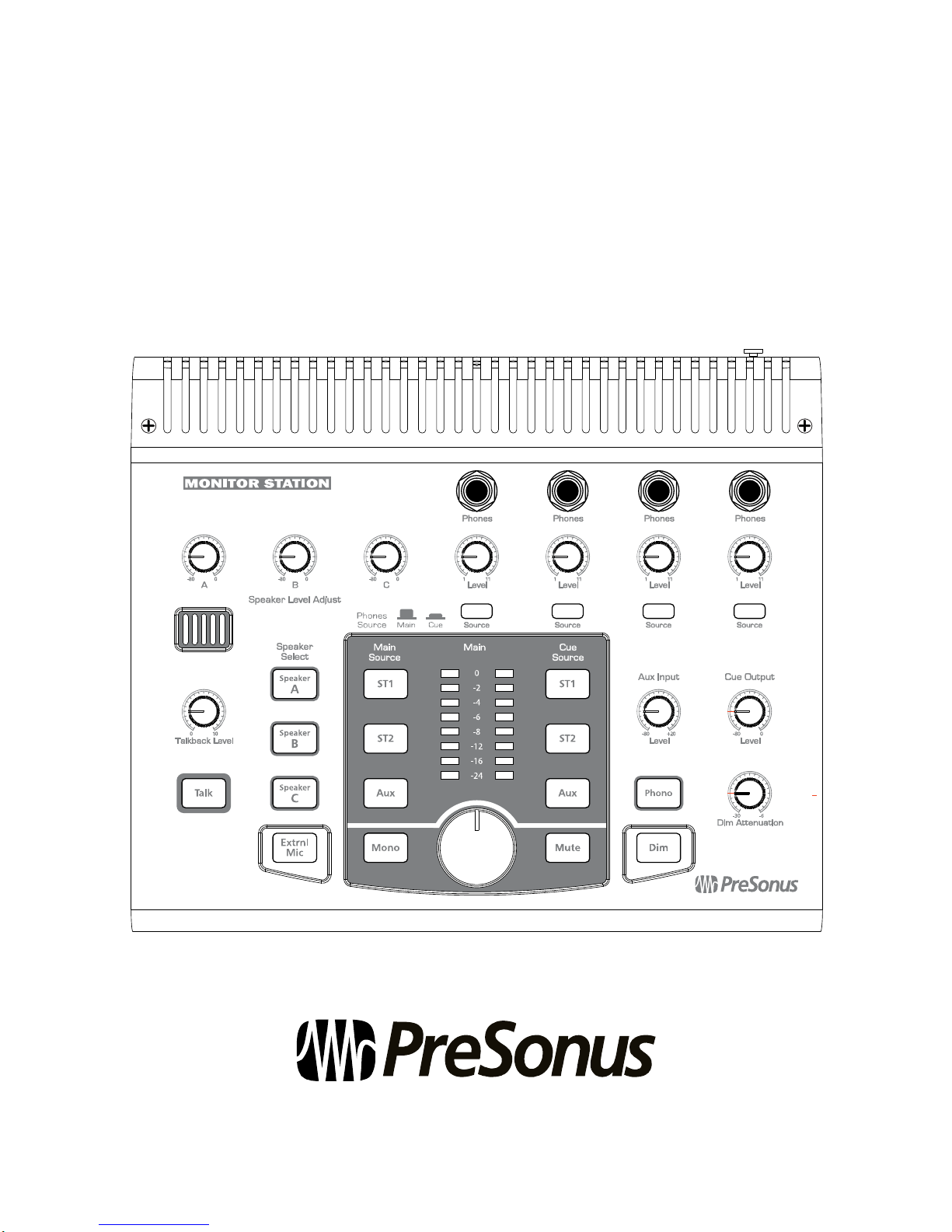
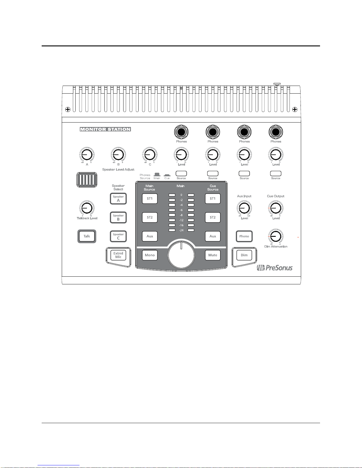
3.1 Front panel Layout .............................................................................................................................. 14
3.1.1 Talkback ...................................................................................................................................... 14
3.1.2 Headphones ................................................................................................................................. 15
3.1.3 Aux/Cue Control ........................................................................................................................... 15
3.1.4 Source Control ............................................................................................................................. 16
3.1.5 Speaker Control ........................................................................................................................... 17
3.1.6 Main Level Control ...................................................................................................................... 18
3.2 Back Panel Layout ............................................................................................................................... 19
3.2.1 Inputs .......................................................................................................................................... 19
3.2.2 Outputs ........................................................................................................................................ 20
3.2.3 Power .......................................................................................................................................... 20
4 TECHNICAL INFORMATION
4.1 Frequently Asked Questions .................................................................................................................. 21
4.2 Troubleshooting ................................................................................................................................... 22
4.3 Specifications ...................................................................................................................................... 23
4.4 Block Diagram ..................................................................................................................................... 25
1
1.1 INTRODUCTION
OVERVIEW
Thank you for purchasing the Monitor Station. PreSonus Audio Electronics designed the Monitor Station using
high-grade components to ensure optimum performance that will last a lifetime. The Monitor Station is the
ultimate desktop monitoring and communications system for your recording studio. Based on the award-winning
Central Station, the Monitor Station provides talkback, speaker switching, input source switching and four ultra
loud and clear headphone amplifiers to deliver everything you need to control your recording environment.
Please contact us at 225-216-7887 with any questions or comments you may have regarding your Monitor
Station. PreSonus Audio Electronics is committed to constant product improvement, and we value your
suggestions highly. We believe the best way to achieve our goal of constant product improvement is by listening
to the real
your Monitor Station.
Please pay close attention to how you connect your Monitor Station to your syst em. We suggest you use this
manual to familiarize yourself with the features, applications and correct connection procedure for your Monitor
Station before trying to connect it to your studio equipment. This will hopefully alleviate any unforeseen issues
that you may encounter during installation and set up.
Thank you, once again, for buying our product, and we hope you enjoy your Monitor Station!
experts
, our valued customers. We appreciate the support you have shown us through the purchase of
2

OVERVIEW
1.2 FEATURES
The Monitor Station is the ultimate studio control center complete with everything needed for real-world,
modern studio applications. The Monitor Station comes complete with a built-in talkback mic, three source
inputs, three speaker outputs, four headphone amplifiers and control over the routing and level of every element
connected to the Monitor Station – effectively giving you complete control over your entire studio environment.
Its stereo inputs are ready to accommodate virtually any input sources – such as Digital Audio Workstations
(DAWs), analogue and digital mixing consoles, CD players, DJ Turntables, etc. Each of the five inputs features
individual monitoring, which means you can quickly and easily toggle between them for a quick comparison or
reference. The Monitor Station’s three stereo outputs with individual Speaker Level Adjust knobs and Master
Mute, Dim, Mono and Level controls allow you to connect three sets of reference monitors and easily compare
your mix on each of them. The four headphone amplifier outputs with individual source and level controls give
you the ability to feed custom headphone mixes to you or any of the artists in your studio. All this combined
with the built-in talkback microphone make the Monitor Station the cleanest, most powerful piece of gear
custom-tailored to bring your studio together under your complete control.
Summary of features
• Three stereo inputs (two balanced ¼” TRS; one unbalanced RCA)
• Built-in phono preamp on RCA aux input
• Main input source selector for comparing/referencing inputs
• Cue source selector for tailoring headphone and cue mixes
• Three balanced ¼” TRS stereo outputs
• Variable Speaker Level Adjustment for fine-tuned calibration of output levels
• Speaker Select for quick A/B’ing of input source between reference monitors
• Dim button with variable attenuation level
• Mono, Mute and Main Level Control
• Built-in talkback microphone with variable input gain
• External talkback microphone input (balanced XLR)
• Four built-in headphone amplifiers (stereo unbalanced ¼” TRS)
• Individual level adjust knobs for each headphone output
• Main/Cue Source selector for each headphone output
3

OVERVIEW
1.3 WHAT IS IN THE BOX
Your Monitor Station package contains the following:
• Monitor Station Studio Control Center
• Monitor Station Power Source
• PreSonus Warranty Card
4

OPERATION
2.1 QUICK START
The Monitor Station Quick Start guide was written to help get your Monitor Station connected to your system as
quickly as possible. The following step-by-step instructions are based on a common studio environment. Your
actual setup may change based on your needs and applica tio ns.
2.1.1 Connect the power
Before connecting any power supply to the Monitor Station, ensure the power supply meets the input
voltage requirements of the region or country you are using it in. PreSonus only supports the power supply
shipped along with your Monitor Station. If it does not meet your requirements or yo u wish to purchase an
additional power supply, please contact your local dealer or distributor.
1) “Zero” the Main, Cue and Phones level knobs by turning them fully counterclockwise.
If you have speakers or gear connected to the Main L/R outputs, you should also Zero them.
2) Ensure the power switch is set to the ‘OFF’ position ( O down = off ).
3) Connect the included power supply to the Monitor Station’s power input connector and to the
appropriate wall socket.
4) Flip the power switch to the ‘ON’ position ( | down = on ).
2.1.2 Connect the input sources
1) “Zero” the Main, Cue and Phones level knobs by turning them fully counterclockwise.
2) Connect your primary audio source (such as a DAW or Mixer Main Outputs) to the Left and Right
TRS inputs of ST1 on the back of your Monitor Station.
3)
[Optional]:
(such as the auxiliary outputs of your interface or Mixer) to the Left and Right TRS inputs of ST2
on the back of your Monitor Station.
4)
[Optional]:
RCA inputs of Aux/Phono.
Connect your secondary audio source (such as a CD or mp3 player) or cue audio source
Connect another secondary or Cue audio source or a DJ turntable to the Left and Right
5

OPERATION
2.1.3 Calibrate the LED meter
By default, the Monitor Station’s LED meters are calibrated so the red 0 dBVU LED illuminates when the
selected source signals reach +10 dBu. This can be changed so that 0 dBVU references +4, +10 or +18 dBu.
+4 dBu
0 dBVU should reference +4 dBu if any of your monitoring devices have a maximum input of +4 dBu or if
none of your input devices have a maximum (or nominal) output level greater than +4 dBu.
+10 dBu
0 dBVU should reference +10 dBu if any of your monitoring devices have a maximum input of +10 dBu or if
none of your input devices have a maximum (or nominal) output level greater than +10 dBu.
+18 dBu
0 dBVU should reference +18 dBu if any of your monitoring devices have a maximum input of +18 dBu or if
none of your input devices have a maximum (or nominal) output level greater than +18 dBu.
2.1.4 Calibrate the input sources
1) Press and hold the Cue Source ST1 button while powering on your Monitor Station.
1) Press and hold the Cue Source ST2 button while powering on your Monitor Station.
1) Press and hold the Cue Source Aux button while powering on your Monitor Station.
1) “Zero” the Main, Cue and Phones level knobs by turning them fully counterclockwise.
2) Turn the outputs of your primary audio source (connected to ST1) to their lowest setting.
3) Remove all effects processors (i.e. EQs, compressors, reverbs, etc.) from the signal path and play a
clean 0 dB test tone (i.e., a 1 kHz sine wave) through the outputs of your primary audio source.
Select only ST1 as the Main Source, and begin turning up the outputs of your primary audio source
to their Unity Gain setting or until the Monitor Station’s LED meter’s red 0 dBVU LED comes on.
If you are not able to reach Unity Gain (or very close to it) without the red 0 dBVU LED coming
on, ensure you have properly calibrated the LED meter (
section 2.1.3
) then repeat this step.
“Unity Gain” is the level or setting which does not boost or attenuate the signal level and is usually
marked by a “0” on the audio device’s level fader or knob. In many digital interfaces and digital
devices, its maximum level is often also its Unity Gain setting. Please consult your audio device’s
user’s manual or manufacturer’s Website for more information on its levels and adjustments.
[Aux/Phono only]:
maximum level. Instead, engage the Phono preamp (if necessary) and increase the Aux Input Level
knob starting from -80 until the red 0 dBVU LED meter just comes on (and no higher).
4) Repeat steps 1 through 3 for the secondary / cue audio sources connected to ST1 an d A ux/P h o no.
Do not adjust the output level of your audio device if it is set at its optimum or
6

OPERATION
2.1.5 Connect the speakers
1) “Zero” the Main level knob by turning it fully counterclockwise.
2) Connect your primary monitoring system (such as a pair of nearfield reference monitors) to the Left
and Right outputs of Speaker A.
3)
[Optional]:
different make or model) to the Left and Right out puts of Speaker B.
4)
[Optional]:
or subwoofer) to the Left and Right outputs of Speaker C.
2.1.6 Calibrate your speaker levels
The essential purpose of speaker calibration is to ensure a specific metered audio level (typically 0 dBVU)
equals a certain acoustic level (measured in dB SPL) in your studio environment. Depending upon the
method and reference levels used during calibration, proper calibration can help reduce unwanted noise,
minimize the risk of damage to your speaker cones and to your ears, maximize the reference capabilities of
different speaker types and ensure you and/or your listeners are he ari ng the au dio a s the engineer intended.
There are many different methods for calibrating studio monitors. The methods discussed here should not be
misconstrued as the
different gear, clientele and audio mixes may ultimately benefit more from one of the many other methods
available. PreSonus does not suggest the calibration methods provided here are in any way the best or only
recommended methods of calibration when using the Monitor Station. If you wish to calibrate your studio
monitors using a different method, we encourage you to do so.
Every calibration method has something in common, though: test tones. The most commonly used te st tones
are 100 Hz, 1 kHz and 10 kHz sine waves, 40-80 Hz and 500 Hz -2.5 kHz bandwidth-limited pink no ise and
20 Hz - 20 kHz pink noise and white noise. Test tone CDs can be purchased from your local electronics or
entertainment retailer or downloaded off the Internet from a variety of free Websites for use in many
calibration and testing procedures. As a less technical, more subjective and not otherwise idea l alternative,
the chorus of a modern commercial Rock song can be substi tu ted for ful l-b a ndw i dt h pi n k noise.
When calibrating reference monitors in a studio, the acoustic level or sound pressure level (SPL) should be
measured from the mix position at seated ear height. The SPL meter should be held at arms’ length with the
microphone pointed at the center point between the left and right speakers, angled at 45 degrees to ensure an
accurate reading. You should also calibrate the left and right monitors independently; pan the test tone hard
left, calibrate the left monitor, then repeat for the right channel.
When monitoring systems are calibrated using the same method, each system should generate the same
acoustic level when given the same input source. This is especially important when referencing your mix on
different monitoring systems (such as toggling between Speaker A and Speaker B for comparison), because
in an incorrectly calibrated studio, the acoustic level will “jump” when toggling the different systems.
(For example, when calibrated properly, playing an audio through Speaker A then turning Speaker A ‘OFF’
and Speaker B ‘ON’ should not cause a change in level – though it may result in a slight tonal variance due to
the different acoustic properties of the monitoring systems.)
Connect your secondary monitoring system (such as a pair of reference monitors of a
Connect another secondary monitoring system (such as a pair of large studio monitors
only
method or even the
best
method, because different studio environments with
7
 Loading...