

Page 1
BlueTube
Two Channel Microphone / Instrument
Tube Preamplifier
User’s Manual
Page 2

Blue Tube
TWO CHANNEL
MICROPHONE/INSTRUMENT
TUBE PRE-AMPLIFIER
USERS MANUAL
Version 1.0
2000, PreSonus Audio Electronics, Incorporated.
All rights reserved.
Page 3

PreSonus Limited Warranty
PreSonus Audio Electronics Inc. warrants this product to be free of defects in material and
workmanship for a period of one year from the date of original retail purchase. This warranty is
enforceable only by the original retail purchaser. To be protected by this warranty, the
purchaser must complete and return the enclosed warranty card within 14 days of purchase.
During the warranty period PreSonus shall, at its sole and absolute option, to either repair or
replace, free of charge, any product that proves to be defective on inspection by PreSonus or its
authorized service representative. To obtain warranty service, the purchaser must first call or
write PreSonus at the address and telephone number printed below to obtain a Return
Authorization Number and instructions of where to return the unit for service. All inquiries must
be accompanied by a description of the problem. All authorized returns must be sent to the
PreSonus repair facility postage prepaid, insured and properly packaged. PreSonus reserves
the right to update any unit returned for repair. PreSonus reserves the right to change or
improve the design of the product at any time without prior notice. This warranty does not cover
claims for damage due to abuse, neglect, alteration or attempted repair by unauthorized
personnel, and is limited to failures arising during normal use that are due to defects in material
or workmanship in the product. Any implied warranties, including implied warranties of
merchantability and fitness for a particular purpose, are limited in duration to the length of this
limited warranty. Some states do not allow limitations on how long an implied warranty lasts, so
the above limitation may not apply to you. In no event will PreSonus be liable for incidental,
consequential or other damages resulting from the breach of any express or implied warranty,
including, among other things, damage to property, damage based on inconvenience or on loss
of use of the product, and, to the extent permitted by law, damages for personal injury. Some
states do not allow the exclusion of limitation of incidental or consequential damages, so the
above limitation or exclusion may not apply to you. This warranty gives you specific legal rights,
and you may also have other rights, which vary form state to state. This warranty only applies to
products sold and used in the United States of America. For warranty information in all other
countries please refer to your local distributor.
PreSonus Audio Electronics, Inc.
7257 Florida Blvd.
Baton Rouge, LA 70806
(225) 216-7887
2000, PreSonus Audio Electronics, Incorporated. All rights reserved.
Page 4

1 Overview
1.1 Introduction 4
1.2 Features 4
2 Controls & Connections
2.1 Front Panel Basic Layout 7
2.2 Preamplifier Section 9
2.3 Back Panel Basic Layout 11
3 Operation
3.1 Dynamic Microphones 14
3.2 Phantom Powered Microphones 14
3.3 Instrument Input 14
3.4 Some Thoughts on Vacuum Tubes
3.5 Mounting Instructions
4 Technical
4.1 Specifications 16
Page 5

1.1 INTRODUCTION
Thank you for purchasing the PreSonus BlueTube Two
Channel Microphone / Instrument Tube Preamplifier . This
pre-amp was designed using state of the art components to
deliver crystal clear audio for an infinite period of time. We
believe the BlueTube to be an exceptional sounding unit and
an exceptional value. Please contact us at 1-800-750-0323
with your questions or comments regarding this product.
PreSonus Audio Electronics is committed to constant product
improvement and believes the best way to accomplish this
task is by listening to the experts on our gear, our valued
customers. We appreciate the support you have shown us
through the purchase of this product.
Please pay close attention to how you connect your BlueTube
to your system. Improper grounding is the most common
cause of noise problems found in studio or live sound
systems. We urge you to scan this manual before hooking up
your BlueTube to familiarize yourself with its features and
various applications.
Good luck and enjoy your BlueTube!
1.2 FEATURES
The following is a summary of your Blue Tube’s features:
• Dual Servo Gain Stage. Each channel of your
BlueTube contains a dual servo gain stage (no
capacitors). This provides ultra low noise
performance and wide dynamic control. This gives
Page 6

the Blue Tube the ability to boost the desirable
signal without increasing unwanted background
noise.
• Phantom Power. Each channel of the BlueTube has
48V Phantom power available. When the Phantom
power switch is engaged, power is supplied at a
constant rate to both channels whether one or both
channels are used. This assures optimum
performance of your condenser microphone(s) and
that the signal will be free of distortion due to
insufficient power.
• Phase Reverse. A phase reverse switch is provided
on each channel. This switch enables the user to
invert the phase of a microphone if phase
cancellation is noticed when using identical
microphones in close proximity to one another. The
phase reverse switch also can compensate for
different XLR connector hook-ups where pin
connections have been inverted.
• -20 dB Pad. A 20 dB pad is available on each
channel for reducing the in-coming signal level. This
pad provides a more manageable signal from high
output devices giving the operator greater control
over the in-coming signal and a much reduced
chance of over-driving the input and thereby
avoiding distortion.
• Mic/Instrument Input. Each channel of the
BlueTube has a separate Neutrik Combo XLR / ¼
inch connector is provided on the front of the Blue
Page 7

Tube for signal input from mic XLR or instrument ¼
inch input.
• Drive. The Blue Tube provides a Drive
potentiometer on each channel for controlling the
amount of signal routed to the 12AX7 vacuum tube.
This feature lets you control how much saturation of
the signal occurs. Greater levels of tube saturation
give the signal greater warmth and a richer sound.
This works equally well on mics and instruments.
Page 8

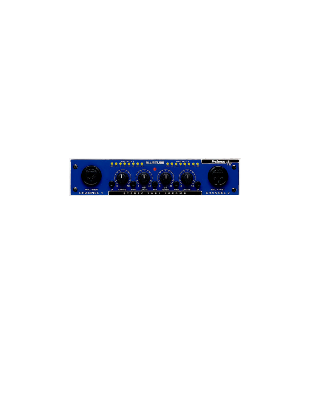
2.1 FRONT PANEL BASIC LAYOUT
Notice that the front panel of the Blue Tube is divided evenly at the
+48V switch in the center of the unit. The input and controls are a
mirror image of each other from left to center and from right to
center. Identical preamplifier sections - Channel One (left to right)
and Channel Two (right to left) – comprise the front panel .
Both preamp channels contain:
• Combination Microphone (XLR) and Instrument (1/4 inch) input
• Phase Reverse Switch
• Drive Control (0 to 30dB)
• -20db Pad
• Gain Control (0 to 40dB)
A single +48 volt phantom power switch is used for both channels.
• Phantom Power Switch
Page 9

Phantom Power is available to each channel input of the Blue
Tube. The 48 volts is supplied by way of the XLR connector for
condenser mics and any other devices requiring continuous power
through the XLR input. This power is supplied at a constant level
allowing use of both inputs simultaneously.
PIN 1 GND
PIN 2 +48v
PIN 3 +48v
XLR connector wiring for Phantom Power
Phase Reverse Switch allows the user to invert the polarity of the
XLR connector by switching pins two and three. The inversion of the
pins of the XLR connector may be necessary to alter the audio
phase of two like microphones to compensate for phase
cancellation. It may be required that the wiring of a cable’s XLR
connector be switched to successfully utilize Phantom power.
-20 dB Pad provides -20 decibels of attenuation with the push of a
button. This is a very useful feature for rapidly reducing the level
coming into the MP20 and thus preventing the input signal from
over-modulating (distorting) the input. This may occur due to high
output level from a microphone or line device. Padding the input
serves to provide increased “headroom” for the operator.
Drive. The Blue Tube Drive control increases the amount of signal
routed through the 12AX7 vacuum tube. The effect achieved by this
procedure can be subtle to extreme, depending on the setting being
used. A “warming up” of the sound can be noticed at lower
Page 10

settings. This desirable effect is especially good for microphones
and on an electric bass and the resulting sound is infinitely richer
and sweeter. An overdriven signal can be achieved by significantly
raising the level of the Drive control. This overdriven tube effect is
extremely useful in providing cool guitar sounds and way cool for
use with harmonicas for that authentic “Blues harp” vibe. The
limits on the possibilities of the Drive control are up to you, your
application and your imagination. Experiment!
Gain. This control governs the amount of boost to the signal being
processed by the pre-amplifier. Dynamic mics and instruments
without pre-amps will normally require more gain than condenser
mics and instruments that have a built-in pre-amp (care should be
taken with instruments having their own built-in pre-amp not to
overdrive the input of the Blue Tube). If you should require more
signal out of the pre-amp for a hotter recording level or to
drive an input of some down stream device harder, cranking
up the gain should provide all the signal that you’ll need.
Page 11

2.4 BACK PANEL BASIC LAYOUT
PIN 1 GND
PIN 2 High (+)
PIN 3 Low (-)
Cable Wiring Diagram for Input and Output XLR
The Output XLR Connector is servo balanced and operates at
+4dBu.
TIP High (+)
SLEEVE GND (-)
Cable Wiring Diagram for Input and Output ¼” Phone Plug
The Output ¼” Phone Connector is unbalanced and operates at
-10 dBv.
Page 12

3.1 DYNAMIC MICROPHONES
Dynamic microphones are characterized by lower output levels.
Hence, more gain is needed to amplify a dynamic microphone to
operating level. Occasionally it is necessary to add the –20dB pad to
the microphone to avoid distortion (e.g. when recording
percussion). Do not use phantom power when using dynamic
microphones.
3.2 PHANTOM POWERED MICROPHONES
Phantom powered microphones such as condenser and some
ribbon microphones require external power to pre-amplify the
microphone acoustic pickup. These microphones typically have
much higher output than dynamic microphones. Hence the –20dB
pad is almost always necessary when close micing to avoid clipping
the amplifier.
3.3 INSTRUMENT INPUT
The instrument input is designed to handle ¼” plugs from
instruments such as guitars and basses. This instrument input is an
ultra high impedance amplifier designed to allow the full audio
potential of an acoustic or electric instrument pickup to be realized.
Care should be taken not to overdrive the input with instrument
preamplifiers.
Page 13

3.4 SOME THOUGHTS ON VACUUM TUBES
The Blue Tube comes supplied with a 12AX7 vacuum tube
that meets or exceeds the stated performance criteria for the
unit. We expect some owners of the Blue Tube will try
different tubes to investigate the various performance
possibilities they might provide. Tube replacement can be
easily accomplished by first unplugging the unit from the
electrical outlet and removing the screws which attach the top
to the chassis. The tube is mounted in a transverse fashion
and care should be taken to properly align the pins on the
tube to the corresponding holes in the receptacle. Make sure
the tube is completely seated in the receptacle and replace
the top of the unit before restoring power to it. Remember:
Tube life and performance are affected by how often a tube is
used and by how hard the tube is driven when in use. Signs of
wear may be exhibited by poor performance or by the tube
becoming “microphonic”. Periodic replacement of vacuum
tubes is recommended . The time between the suggested
replacement varies greatly with use. If you notice a
deterioration in sound quality then it’s time to change the
tube.
Mounting Instructions for the PreSonus Custom
Page 14

Rack Rack Mount Adapter
When mounting the Blue Tube In a PreSonus rack adapter with a
Blue Max, the Blue tube must be mounted on the left side of the
rack adapter to avoid hum being introduced into the unit by
proximity to the power transformer in the Blue Max. The Mounting
of the Blue Tube to the left of the Blue Max will minimize any field
effect the magnetism that the Blue Max’s transformer may have. It
should be noted that proximity to computer CPU’s, power supplies,
or other electrical devices may introduce undesired audio artifacts
into the output signal of the Blue Tube or any microphone
preamplifier. Care should be taken with where a mic pre-amp is
placed during operation to insure no electrical interference can
occur.
Page 15

Blue Tube Technical Specifications:
Number of Channels Two
Performance
THD + Noise(Unweighted) 0.05%@0dBTubeDrive
10%@ 30dB Tube Drive
Noise Floor -94dBu
Signal to Noise >90dB
Power Supply Rejection >98dB
Amplifier Type Dual Servo
Input
Connectors Neutrik Combo
Input Impedance, XLR 5k Ohms
Input Impedance, High Z ¼” 1Meg Ohms
Output
Output Impedance, XLR Balanced 51 Ohms
Output Impedance, ¼”TRS Unbalanced 51 Ohms
Panel Controls
Tube Drive 0dB to +30dB
Gain 0dB to +40dB
Phase Reversal
- 20dB Pad
+ 48V Phantom Power
Metering
8 Segment LED -28dBu to +18dBu
Power Supply
Type Linear Supply
Input 18 VAC/100mA
Power 15 WATTS
Physical
Weight 4lbs.
Size ½ U Rack
Dimensions 8” X 5” X 1.75”
Mounting Universal Rack Tray Insert
Chassis Steel
Front Panel Brushed Aluminum
As a commitment to constant improvement, PreSonus, Inc. reserves the right to
change any specification stated herein at any time in the future without
notification.
Page 16

 Loading...