

Page 1
INSTALLATION MANUAL
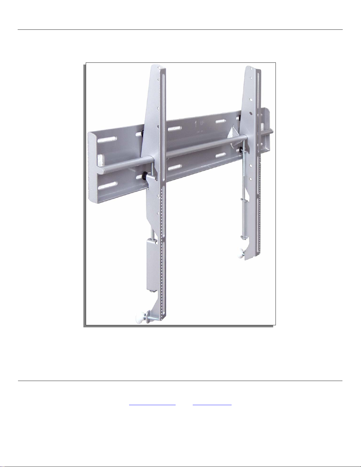
PWM-F110
Premier Mounts
3130 E. Miraloma Avenue
Anaheim, CA 92806
Phone: (800) 368-9700 Fax: (800) 832-4888
mounts@mounts.com
www.mounts.com
Page 2

PBL-110 Projector Mount
Page - 2 - Installation Manual
Page 3

PWM-F110
Table of Contents
Warning Statements ...........................................................................................................................................- 4 -
Parts List ............................................................................................................................................................- 6 -
Installation Tools ...............................................................................................................................................- 6 -
Mounting Bracket Installation ...........................................................................................................................- 7 -
Wall Stud Location ..........................................................................................................................................- 10 -
Installing the Flat Panel Display ......................................................................................................................- 14 -
Technical Specifications ..................................................................................................................................- 16 -
Warranty ..........................................................................................................................................................- 17 -
Contact Premier Mounts ..................................................................................................................................- 17 -
Notes ................................................................................................................................................................- 18 -
Installation Manual Page - 3 -
Page 4
PWM-F110
Warning Statements
Safety Precautions
This wall mount should be installed by qualified personnel having sufficient skill and competence to install it. Qualified installation
specialists or your dealer should install the mount and set up the plasma television in order to avoid personal injury or property damage.
Premier Mounts does not assume liability for injury or damage caused by improper installation, mounting or setup of the plasma
television, misuse, modification or natural disasters.
The entire installation instructions should be fully read and understood, including all of the safety symbols and safety precautions, before
beginning installation. The installation instructions should be read, understood and followed to prevent personal injury or property
damage. Keep these installation instructions in an easily accessible location for future reference.
The wall being considered for mounting must be capable of supporting at least five (5) times the weight of 40Kg. If it is not, the wall
must be reinforced before beginning installation.
Only use specified parts for the installation of the mounting bracket. Do not use the mounting hardware from any other mount or any
other source.
A secured structure wooden stud wall must always support the weight or load of the plasma. Always confirm the center of
the wood stud before beginning the installation. Failure to do so could result in personal injury and physical damage.
Avoid installing the plasma in locations where temperatures and humidity are excessively high, or contact with any water or
vapors possible. This could result in fire, electrical shock and damage to the plasma television. Water will damage the wall
structure for wall mount installation. The permissible temperature is (0-40ºC) and humidity is (20%-80%).
The mount is designed to be used on vertical walls only. Do not install near or on doors, angled ceilings, walls, or any other
installations other than wall mounting. Failure to do so could result in damage and injury. This wall mount is to be used
only with plasma television. Use with any plasma television other than is prohibited and may cause injury and damage.
Make sure the plasma mounting area is completely free of internal or external wires, pipes, gas lines, phone lines etc. Failure
to do so will result in injury and damage to the walls, wiring or piping system.
Avoid Installations where there is danger of contact with over excessive dust, oil smoke, and tobacco smoke. Failure to do so
may result in fire or damage to the plasma or its internals.
Do not block the ventilation holes. Sufficient clearance must be left in the area surrounding the plasma and wall mount to
avoid blocking the vents and causing the plasma to overheat which could cause a risk of fire. Leave 100mm or more away
from all of the surrounding four sides for proper airflow.
Do not install in locations where there is vibration, movement or danger of impact. Failure to do so could result in plasma
cracking or falling from the wall causing damage and injury.
Do not install near heater, fireplace, direct sunlight or air conditioning or any other source of direct heat energy. Failure to
do so may result in damage to the plasma television and could cause a risk of fire.
It is not necessarily to open the plasma television prior to installation. Never open the plasma or modify the mount. This
plasma is to be used only as outlined in the installation instruction. Failure to do so may result in damage and injury. If a
malfunction or problem occurs, contact the nearest dealer.
At least two qualified people should always perform the installation work. Injury and damage can result from dropping or
bending the plasma television.
All six (6) M8 bolts (part B) and quick release sleeves (part A) must be firmly tightened and secured to the plasma television in
the correct locations. If the quick release sleeves are not properly installed, do not hang the plasma television to the wall
mount. Damage and Injury could result from the plasma falling down.
All four (4) Lag bolts must be properly secured to the 450mm wall studs. The lag bolts must always be secured through the
center of the wood studs. Failure to do so could result in the plasma falling from the wall causing damage to the plasma and
personal injury.
All bolts must be properly tightened and secured before installing the plasma display. Failure to do so could result in the
plasma falling causing damage to the plasma and personal injury.
Objects on the wall may collect dust quicker than anticipated. Check periodically for dust accumulation. Refer to the plasma
installation instructions for cleaning instructions.
Do not play around the plasma or throw any objects near or at the screen. The glass screen is very sensitive and may scratch
or break or cause the plasma television to fall from the wall causing personal injury and damage.
Page - 4 - Installation Manual
Page 5

PWM-F110
Mount Overview
This PWM-F110 Plasma Wall Mount may be sold as part of a system or as an independent component. Whichever way it is
purchased the installer must take care to use only the hardware and components that come included in this package and that it
only be used in conjunction with the appropriate Plasma Television.
The PWM-F110 plasma wall mount is to be used to attach a plasma television vertically to an appropriate wall. In order to mount
the plasma television, it is necessary to attach the enclosed mount using the enclosed hardware to the wall and to use enclosed
hardware to attach to the back of the plasma television, and then to attach them together.
As described below, there are three main steps involved in the mounting process:
1. Attach the six Quick Release Sleeves to the rear of the plasma television.
2. Position and attach the Plasma Wall Bracket to an appropriate wall.
3. Lift and attach the plasma television to the Plasma Wall Bracket.
Read the installation instructions completely in order to ensure a complete understanding of the entire installation procedures
before beginning the installation process. It is recommended that qualified installers install this product
.
Installation Manual Page - 5 -
Page 6
PWM-F110
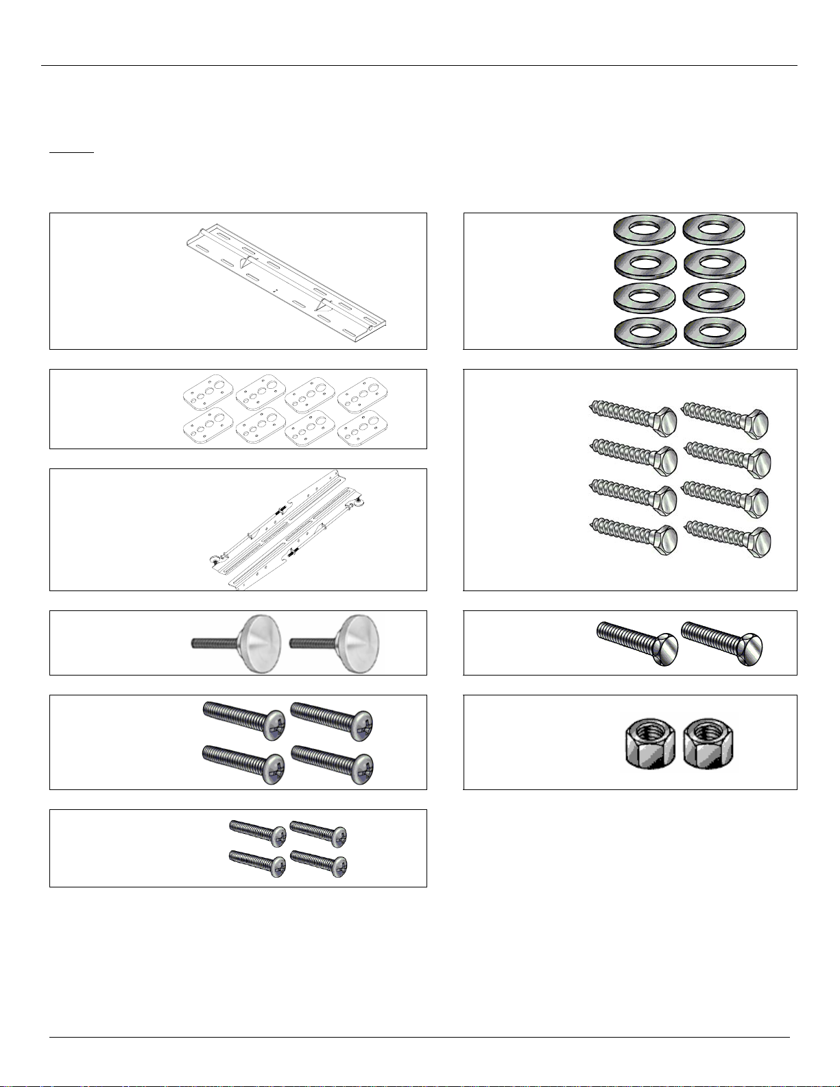
Parts List
NOTE: This wall mount is shipped with all proper installation hardware and components. Make sure that
Wall Plate
(2ea)
Griplates™
(8ea)
Mounting
Brackets
(left and
right)
none of these parts are missing and/or damaged before beginning installation. If there are parts
missing and/or damaged, please stop the installation and contact Premier Mounts
(800) 368-9700 Ext.224.
5/16” Flat
Washers
(8ea)
5/16” x 3”
Lag Bolts
(wooden
studs only)
– (8ea)
Wall
Bumpers
(2ea)
M8 x 20mm
Phillips
Head Screws
(8ea)
M4 x 16mm
Phillips
Head Screws
(8ea)
M8 x 16mm
Hex Head
Bolt (2ea)
M8 Hex Nut
(2ea)
Installation Tools
Phillips Head Screw Driver Soft Material/ Blanket Drill Gun
Pencil Tape Measure 5/16” Socket and Wrench
Level
Page - 6 - Installation Manual
Page 7

PWM-F110
Mounting Bracket Installation
NOTE: Proper installation procedure by qualified personnel as outlined in the installation instructions must
be adhered to. Failure to do so could result in serious personal injury and possible damage to the
flat panel.
WARNING: INVERT THE FLAT PANEL AND PLACE IT ON A SOFT, FLAT SUFRACE TO PREVENT DAMAGE
TO THE FLAT PANEL. USE A BLANKET, FOAM, ETC. FAILURE TO DO SO WILL RESULT IN
DAMAGING THE FLAT PANEL. DO NOT LAY THE FLAT PANEL ON THE FLOOR WITHOUT ANY
PROTECTION TO THE GLASS. THE FLAT PANEL IS HEAVY AND FRAGILE. AT LEAST (2)
QUALIFIED PERSONNEL ARE STRONGLY RECOMMENDED FOR INSTALLATION OF THIS
PRODUCT. FAILURE TO DO SO COULD RESULT IN SERIOUS INJURY AND POSSIBLE DAMAGE
TO THE FLAT PANEL.
1. Once the flat panel is inverted, use a measuring tape to find the center of your flat panel measuring
from outside to outside of the chassis (Figure 1).
2. Using a pencil lightly mark the center of your flat panel (Figure 2).
Measuring tape
Inverted flat panelBottom of flat panel
Top of flat panel
C
L
Mark the center
of the flat panel
Inverted flat panel
C
L
Figure 1 Figure 2
Installation Manual Page - 7 -
Page 8

3. If needed, install the nylon spacers to the mounting points on the flat panel (Figure 3).
4. Lay the left and right mounting brackets (stamped arrows facing out) - (Figure 4).
PWM-F110
Center Mark
Nylon Spacers, If Applicable
Inverted Flat Panel
Arrows Facing Out
Figure 3 Figure 4
Mounting Brackets
Bottom of Flat Panel
5. Match the center of viewing guide with the centerline you marked in step 1 (Figure 5).
6. The mounting brackets are designed with a center of viewing guide on the side of them (Figure 6).
Page - 8 - Installation Manual
Page 9

PWM-F110
F
P
P
P
p
Mounting Bracket
C
L
Bottom of Flat
anel
Center of
Viewing Guide
Align the Mounting
Brackets
Bottom of the
lat Panel
Center of Flat
anel
Figure 5 Figure 6
7. The Griplates™ have M4, M5, M6 and M8 hole patterns to fit the hardware that your flat panel requires.
EXAMPLE: If your flat panel uses M8 x 20 Phillip screws, use the M8 mounting points (Figure 7).
8. Once the mounting brackets are aligned, secure the Griplate™ to the flat panel. Use (1) Griplate™ per
mounting point (Figure 8).
NOTE: The dimples of the top plates have to be facing up and the bottom dimples must be facing down.
Dimples Facing
U
Screw Driver
DIMPLES
FACING UP
DIMPLES
FACING UP
DIMPLES
FACING DOWN
Bottom of Flat
anel
M4 M5 M8 M6
3/4"
DIMPLES
FACING DOWN
Figure 7 Figure 8
Installation Manual Page - 9 -
Page 10

W
wood studs.
y
w
PWM-F110
Wall Stud Location
1. Using a (commercially available) wood stud finder, locate four 16" or 24" stud centers behind the wall.
Once found, make a pencil marking on the center of the wood studs (Figure 9).
NOTE
: The wall plates have (3) 16" and (1) 24" mounting slot positions (see Technical Specifications on
Page 17)
2. Measure from the floor to the desired viewing height and mark the wall.
NOTE: This marking will reference the center of your flat panel display once mounted on the wall
(Figure 10).
Wood Stud Finder
(Commerciall
available)
16"
16”
Mark the wall and
the center of the
16”
16"
Measure and
mark the
viewing height
16”
ood studs
behind the
wall
structure.
desired on the
all.
Figure 9 Figure 10
NOTE: Although not depicted in the illustrations shown above, the width of this wall mount will
encompass four wall studs (three wall studs if 24” apart).
Page - 10 - Installation Manual
Page 11

H
PWM-F110
3. To connect the two wall plates, lay them on a flat surface, end to end. Make sure that the holes line up
(Figure 11).
4. Insert two (2) M8 x 16mm Hex Head bolts through the two holes and secure with two (2) M8 Hex nuts
(Figure 11).
5. Place the bottom portion of the wall plate to the reference line and mark the eight (8) lag bolt
mounting points through the wall plate slots on the wall.
6. Level the wall plate with the reference arrow pointing up to the ceiling (Figure 11).
Mounting Surfaces (Figure 14)
Wood studs: Drill eight (8) ¼" pilot holes to the marked wall (16”studs, on center – Figure 12).
Concrete wall: Drill eight (8) 3/8” pilot holes to the marked wall (Figure 18).
Drill Gun
Pilot
oles
16"
Wall Plate
Mounting
Slots
Level
Wood Studs
Figure 11 Figure 12
NOTE
: Although not depicted in the illustrations shown above, the width of this wall mount will
encompass four wall studs (three wall studs if 24” apart).
Page - 11 - Installation Manual
Page 12

PWM-F110
7. Level and secure the plate to the wall with the reference arrow facing up to the ceiling.
8. Secure the plate using the eight (8) 5/16" lag bolts and flat washers (supplied) – (Figure 13).
CAUTION: Do not over tighten the lag bolts.
NOTE: Use a minimum diameter of 5/16” x 3” long wood screws.
Level
5/16" x 3" lag
bolts and (4) flat
washers (4ea)
Wall Plates
Figure 13
NOTE: Although not depicted in the illustrations shown above, the width of this wall mount will encompass
four wall studs (three wall studs if 24” apart).
Installation Manual Page - 12 -
Page 13

PWM-F110
9. Level and secure the plate to the wall with the reference arrow facing up to the ceiling.
10. Use a minimum diameter of 5/16” x 2 ¼” large concrete wedge anchors (commercially available) –
(Figure 14).
CAUTION
NOTE
: Do not over tighten the wedge anchors bolts.
: Use a minimum diameter of 5/16” x 2 ¼” long wedge anchors (commercially available).
(4) 5/16" x 2 ¼”
wedge anchors
(commercially
available)
Wall Plate
(4) 5/16" x 2 ¼”
wedge anchors
(commercially
available)
Figure 14
NOTE
: Although not depicted in the illustrations shown above, the width of this wall mount will encompass
four wall studs (three wall studs if 24” apart).
Page - 13 - Installation Manual
Page 14

PWM-F110
Installing the Flat Panel Display
WARNING: AT LEAST (2) QUALIFIED PERSONNEL ARE STRONGLY RECOMMENDED FOR INSTALLATION
OF THIS PRODUCT. FAILURE TO DO SO COULD RESULT IN SERIOUS INJURY AND POSSIBLE
DAMAGE TO THE FLAT PANEL.
1. Raise the flat panel with the LEFT and RIGHT mounting brackets secured to the flat panel and insert
the top hooks from each bracket to the rod from the wall plates (Figure 15).
Wall Plate
Top
Figure 15
Installation Manual Page - 14 -
Page 15

W
W
PWM-F110
2. Make any lateral shift adjustment and lock it by tightening the two (2) ¼”-20 Phillips screws found on
the bottom of the mounting brackets. Use the wall bumper to adjust your flat panel.
CAUTION: Do not over tighten the ¼”-20 screws to the rods (Figure 16).
: To remove the flat panel from the wall, simply back off the ¼”-20 screws using a Phillips
NOTE
screwdriver and lift the unit of the wall carefully.
all Plate
all
Bumper
Figure 16
Page - 15 - Installation Manual
Page 16

PWM-F110
Technical Specifications
3.500
5.000
(88.9)
(127)
H
28.000
(171.2)
16.000
(406.4)
C
L
1.245
(31.75)
A
B
21.790
C
L
(553.4)
C
16.000
(406.4)
16.000
(406.4)
G
16.000
(406.4)
24.290
(616.97)
F
D
E
21.790
(553.4)
1.943
(49.3)
B
H
A
5.000
(127)
F
Figure 17
Installation Manual Page 19
Page 17

PWM-F110
Warranty
Limited Lifetime Warranty
All Premier Mounts products carry a limited lifetime warranty from ship date against defects in materials and
workmanship. Premier Mounts is not liable for improper installation that results in damage to mounts,
adapters, display equipment or personal injury.
Contact Premier Mounts
In the event of missing and/or damage equipment, or technical questions, the following information can help
in the completion of the installation.
Customer Service – (800) 368-9700 Ext. 224
Technical Support – techsupport@mounts.com
Page 20 Installation Manual
Page 18

PWM-F110
Notes
Premier Mounts
3130 E. Miraloma Avenue
Anaheim, CA 92806
Phone: (800) 368-9700 Fax: (800) 832-4888
mounts@mounts.com
www.mounts.com
Installation Manual Page - 18 -
 Loading...