

Page 1

PTM-B
Tilt/Pivot Mount
Installation Instructions
Premier Mounts
3130 E. Miraloma Avenue
Anaheim, CA 92806
Phone: (800) 368-9700 Fax: (800) 832-4888
[email protected] www.mounts.com
IN-PTMB.R0
Page 2
TABLE OF CONTENTS
Warning Statements 3
Parts List 4
Installation Tools 4
Wood Stud Installation 5
Optional Concrete Installation 5
PTM-B Installation 6
PTM-B Adjustment 6
Attaching the Display 7
UFP-200 Adapter Plate 7
Technical Specifications 8
Warranty 8
Contact Premier Mounts 8
Page 2 Installation Instructions
Warranty
Limited Lifetime Warranty
All Premier Mounts products carry a limited lifetime warranty from ship date against defects in materials and
workmanship. Premier Mounts is not liable for improper installation that results in damage to mounts,
adapters, display equipment or personal injury.
Contact Premier Mounts
In the event of missing and/or damage equipment, or technical questions, the following information can
help in the completion of the installation.
Customer Service - (800) 368-9700
Technical Support - [email protected]
PTM-B
Page 3
Installation Instructions Page 3
Warning Statements
WARNING: THE WALL STRUCTURE MUST BE CAPABLE OF SUPPORTING AT LEAST A MINIMUM
WEIGHT OF 50 LBS. IF NOT, THE WALL MUST BE REINFORCED. PROPER INSTALLATION
PROCEDURE BY A QUALIFIED SERVICE TECHNICIAN, AS OUTLINED IN THE INSTALLATION
INSTRUCTIONS, MUST BE ADHERED TO. FAILURE TO DO SO COULD RESULT IN SERIOUS
PERSONAL INJURY, OR EVEN DEATH.
W
ARNING: SAFETY MEASURES MUST BE PRACTICED AT ALL TIMES DURING THE INSTALLATION OF
THIS PRODUCT. USE PROPER SAFETY GEAR AND TOOLS FOR THE INSTALLATION
PROCEDURE TO PREVENT PERSONAL INJURY.
W
ARNING: PRIOR TO THE INSTALLATION OF THIS PRODUCT, THE INSTALLATION INSTRUCTIONS
SHOULD BE READ AND COMPLETELY UNDERSTOOD. THE INSTALLATION INSTRUCTIONS
MUST BE READ TO PREVENT PERSONAL INJURY AND PROPERTY DAMAGE. KEEP THESE
INSTALLATION INSTRUCTIONS IN AN EASILY ACCESSIBLE LOCATION FOR FUTURE
REFERENCE.
Indicates that the power plug is to be disconnected from the power outlet.
Safety precautions must be taken at all times.
Warning and Caution statements.
A secure structure must support the weight, or load, of the display. When mounting to a wall that contains
wooden studs, dead center of the wooden stud must be confirmed prior to installation.
Do not install on a structure that is prone to vibration, movement or chance of impact. Failure to do so could result
in damage to the display and/or damage to the mounting surface.
Do not install near heater, fireplace, direct sunlight, air conditioning or any other source of direct heat energy. Failure
to do so may result in damage to the display and could increase the risk of fire.
At least two qualified people should perform the installation procedure. Injury and/or damage can result from dropping or mishandling the display.
Recommended mounting surfaces: wooden studs and solid-flat concrete. If the mount is to be installed on any surface other than wooden studs, use suitable hardware (which is commercially available).
Contact Premier Mounts with any technical/ installation questions.
PTM-B
Page 4
Page 4 Installation Instructions
Parts List
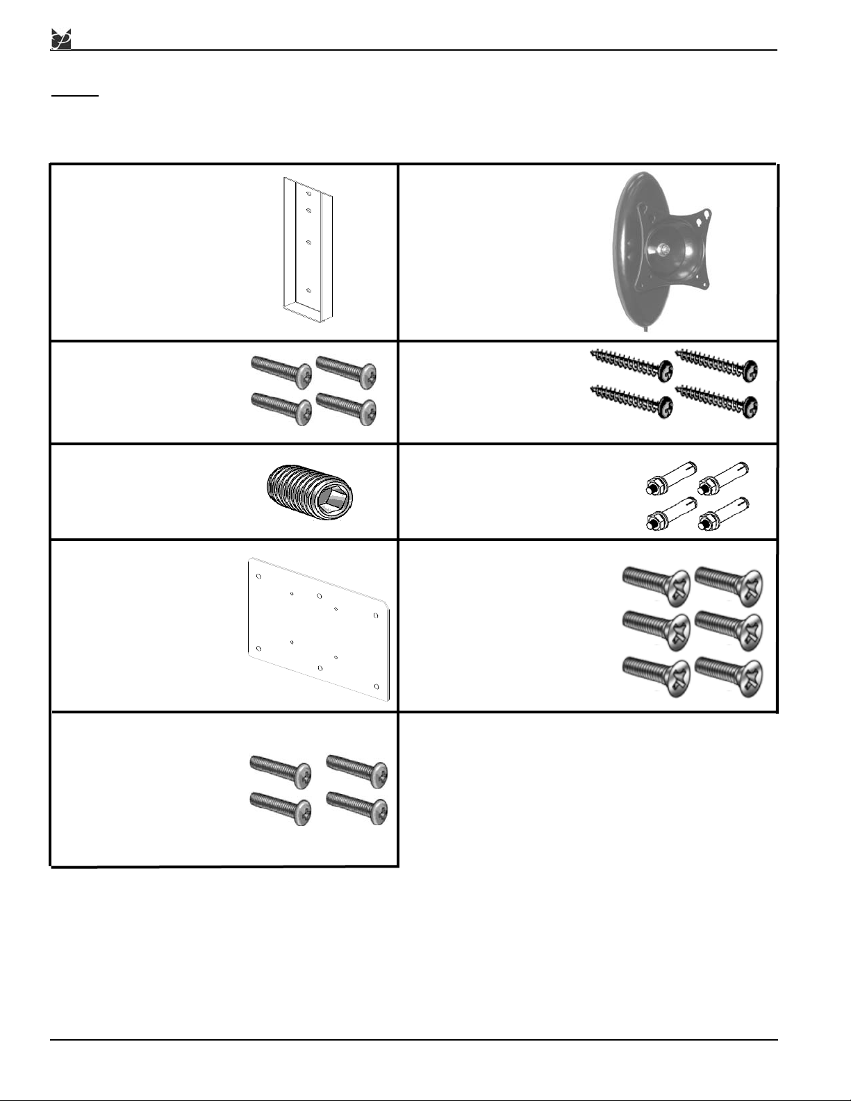
NOTE: This mount is shipped with all installation hardware and components. Make sure that none
of these parts are missing and/ or damaged before beginning installation. If there are parts
missing and/or damaged, please stop and contact Premier Mounts - (800) 368-9700.
Installation Tools
Phillips Head Screw Driver Portable Drill
Soft Material/ Blanket Pencil
5/16” Drill Bit (for wedge anchors) Level
Tape Measure Ratchet with 14mm Drive Socket
Stud Finder (Sold Separately) M3 Allen Wrench (Supplied)
Mounting Backplate (Qty 1)
#14 x 2”Wood
Screws (Qty 4)
M4 x 10mm Phillips
Head Screws (Qty 4)
Tilt/Pivot Mount (Qty 1)
PTM-B
1/4” x 1-1/2” Wedge Anchors
(Qty 4). These are used only
for concrete applications.
M6 x 35mm Set Screw
(Qty 1)
UFP-200 Plate (Qty 1)
M4 x 5mm Phillips
Screws (Qty 4)
M4 x 10mm Flat Head
Phillips Screws (Qty 6)
Page 5
Installation Instructions Page 5
Wood Stud Installation
PTM-B
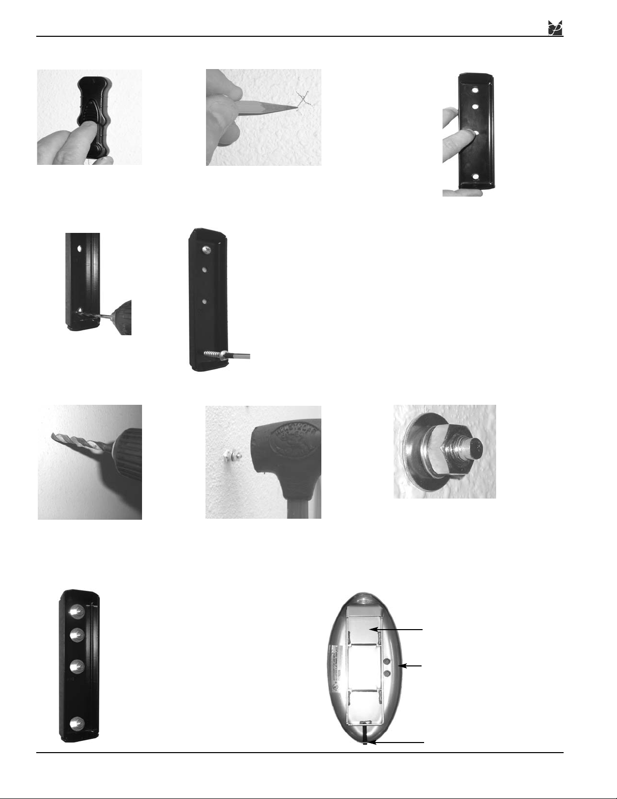
Determine where the
mount location will be.
Use a stud finder to locate
the nearest wall stud.
Once the stud has been located,
use a pencil to mark the center of
the stud.
Use the level (supplied) to make sure
the backplate is level from top to bottom.
Place the back plate over the first
whole, and use a pencil to mark the rest
of the holes.
Use a drill and a 1/8" drill bit
to pre-drill the mounting
holes.
Use the provided wood
screws to attach the back plate
to the mounting surface.
Optional Concrete Installation
Drill the mounting holes
where the marks were
made with a pencil. Use a
5/16" concrete drill bit
(commercially available).
Once the holes have been
drilled, place the wedge anchor
into the hole. Using a hammer,
gently tap into place.
Correctly seated wedge
anchor bolt.
Place the backplate over the
wedge anchors once the wedge
anchors have been correctly
inserted into the mounting surface. Place the washer, locking
washer and nut onto the threaded
shaft and tighten.
Backplate Receptacle
Mount Base
Locking Screw Access Hole
Page 6
Page 6 Installation Instructions
PTM-B
PTM Installation
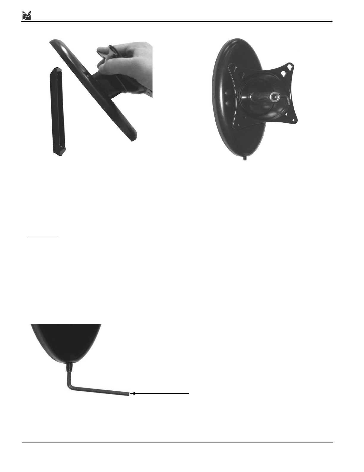
1. The reverse side of the mount must be mounted to the back
plate that is attached to the wall. The back of the mount
contains an elongated rectangle. The back plate
receptacle must be placed over the top of the back plate, so
that the entire mount “hangs” on the back plate.
2. Locate the access hole at the bottom of the mount base. Install
the M6 x 35mm set screw with the M3 Allen wrench.
3. Turn the Allen wrench clockwise (viewed from below) until
the screw is secure.
W
ARNING: Failure to fully tighten the locking screw may
result in possible damage to your display.
PTM Tension Adjustment
To adjust the tension of the PTM, use
the 14mm socket and Allen Wrench.
The tension nut is located on the face
of the PTM.
Use the M3 Allen Wrench (supplied) to tighten the
locking screw that is located on the bottom of the
mount base. This locking screw will prevent the
mount and display from being lifted off of the wall
plate.
M3 Allen Wrench
Page 7
PTM-B
Installation Instructions Page 7
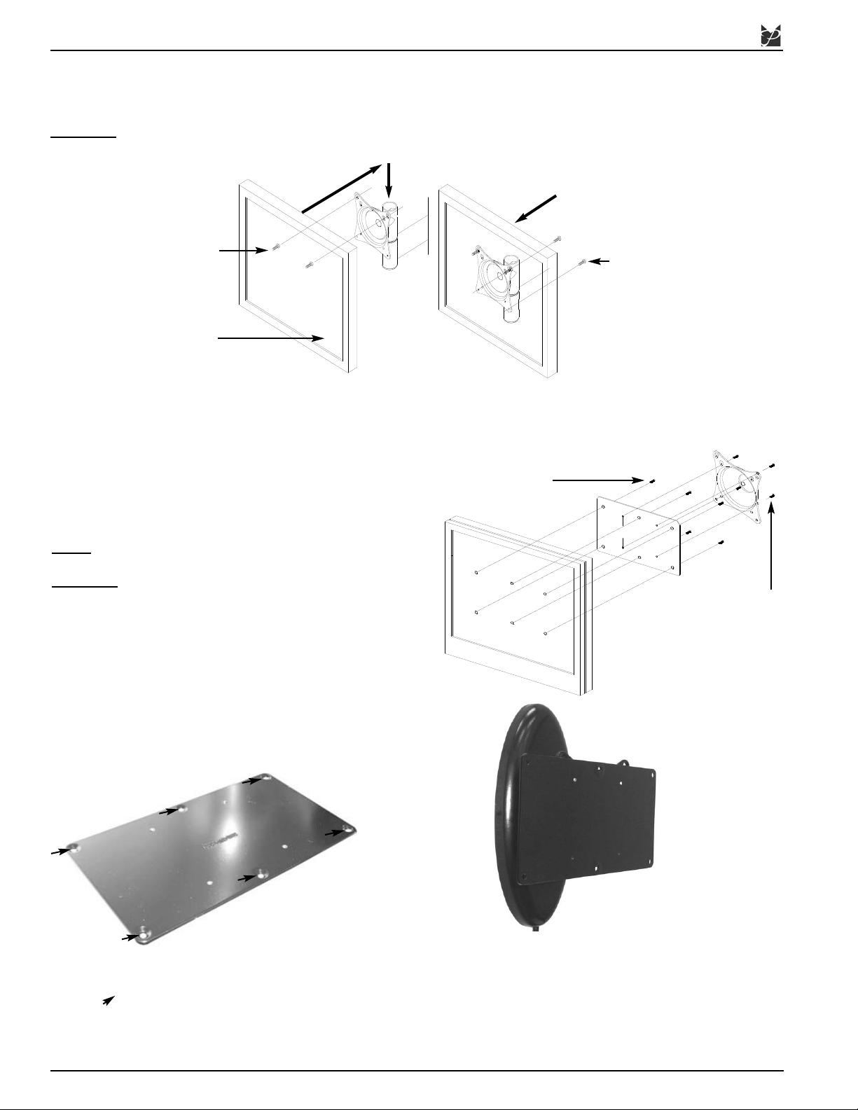
For the PTM-B, it is suggested that the
mount and adapter plate be attached to the
display while the display is on the ground.
The reason for this is because once the
display is attached, there is limited space
behind the unit to use a screwdriver to
tighten the screws.
UFP-200 Adapter Plate
Use six (6) M4 x 10mm screws to attach the plate to the
display ( - 6 total).
Install the top two M4 x 5mm screws into the UFP-200
plate. Do not thread tight.
Attaching the Display
1. Loosely tighten two (2) M4 x 10 phillip screws to the top of the mounting points.
2. Insert the head of the screws through the keyhole slots and then secure the bottom two (2) M4 x 10 phillip screws to
secure the flat panel to the mounts, then tighten the upper M4 screws.
CAUTION
: Do not over tighten the M4 screws.
Display
M4 x 10mm
Phillips Head
Screws
M4 x 10mm
Phillips Head
Screws
VESA75
1. Attach the UFP-200 Adapter Plate to the back of the display
using the six (6) M4 x 10mm screws.
2. Attach the PTM mounting plate to the back of the
UFP-200 using the four (4) M4 x 5 mm screws.
NOTE
: If your flat panel is not a VESA 75/100, the UFP-200
Adapter Plate must be used.
CAUTION: DO NOT OVERTIGHTEN THE SCREWS.
M4 x 10mm Phillips
Head Screws
M4 x 5mm
Phillips Head
Screws
Page 8
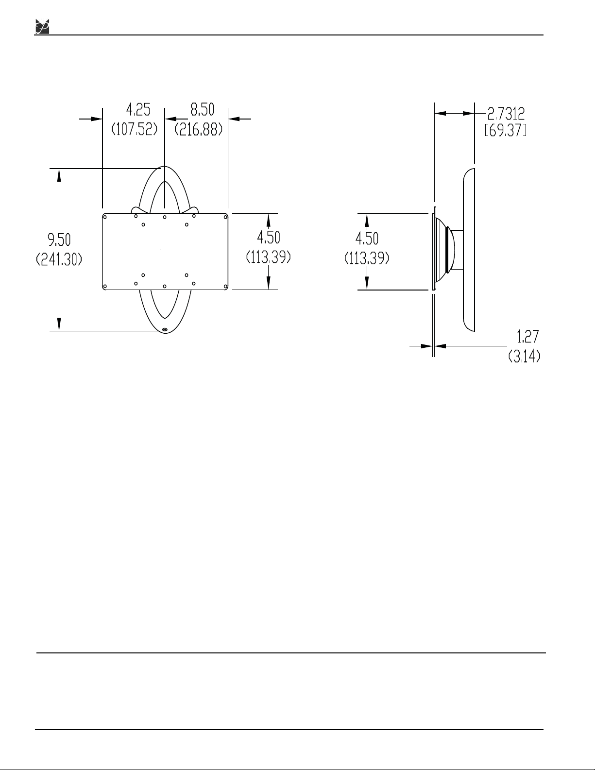
Technical Specifications
All measurements in inches/(mm).
NORTH AMERICA
3130 E. Miraloma Ave.
Anaheim, CA 92806 USA
USA and Canada -
Phone: 800-368-9700
Fax: 800-832-4888
www.mounts.com
EUROPE
Swallow House,
Shilton Industrial Estate,
Shilton, Coventry, England
CV79JY
Phone: +44 (0) 2476 614700
Fax: +44 (0) 2476 614710
AUSTRALIA, NEW ZEALAND,
OCEANIA (DISTRIBUTOR)
P.O. Box 295
Mordialloc Victoria 3195
Australia
Phone: 03 9586 6330
www.premiermounts.com.au
PTM-B
Page 8 Installation Instructions
 Loading...