

Page 1

INSTALLATION MANUAL
PROJECTOR MOUNT MODEL
PSD-VHSA
3130 E. Miraloma Ave. Anaheim, CA 92806 Phone: 800 368-9700 Fax: 800 832-4888
VISIT US AT WWW.PREMIERMOUNTS.COM
Page 2

Introduction
This adjustable-height tabletop stand allows you to configure your plasma display either horizontally or vertically (on PSM series only). It mates directly with
any of our PSM Series flat wall mounts. Constructed of dual heavy-gauge steel with a unique laser cut solid base plate, this adapter is both attractive and
sturdy. It supports a heavy display at its center of gravity. Our floor stands DO NOT include mounts. You will need to order the appropriate PSM or CTM
series mount for your plasma in order to complete the system.
Contents
o Safety & precautions
o PSD-VHSA diagrams
o Installing the height adapter (PP-SPA) adapter
o Measurements
o Securing the back plate
- 2 -
Page 3
g
p
Safety & Precautions
WARNING: Safety precaution measures must be practiced at all times during the installation of this product. Use proper safety gear and tools for the
installations
rocedure to prevent personal injury or damage to the plasma displays or plasma mounts.
The floor or tabletop structure must be capable of supporting at least five (5) times the weight of plasma display. If not, the floor or tabletop
must be reinforced. Proper installation procedure by qualified personnel as outlined in the installations instructions must be adhered to.
Failure to do so could result in serious personal injury
The entire installation instructions should be fully read and understood, including all of the safety symbols and safety precautions, before
be
inning installation. The installation instructions should be read, understood and followed to prevent personal injury or property damage.
Keep these installation instructions in an easily accessible location for future reference.
Indicates that the power plug is to be disconnected from
the power outlet.
Contact Premier Mounts for any questions
Safety precautions must be taken at all times.
Warning and caution in general
A suitable floor or tabletop must always support the weight or load of the plasma. Always confirm the weight load of the installation
structure before installing the PSD-VHSA stand.
Do not install in locations where there is vibration, movement or danger of impact. Failure to do so could result in plasma cracking or
tipping over from the floor or tabletop causing damage to the plasma and injury.
Do not install near heater, fireplace, direct sunlight or air conditioning or any other source of direct heat energy. Failure to do so may
result in damage to the plasma display.
At least two qualified people should always perform the installation work. Injury and damage can result from dropping or mishandling
the plasma display.
- 3 -
Page 4
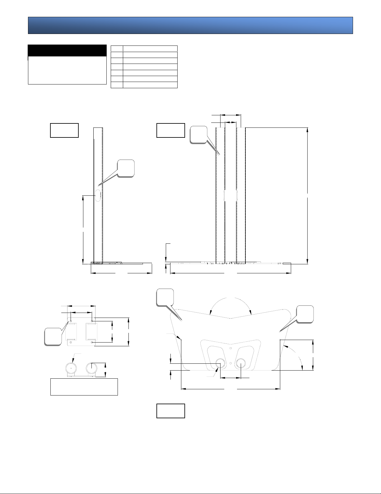
Mount Diagrams
MATERIAL:
4 (ga) P & O base plate &
2" (dia) tubing
COLOR: Sinterflex
PSD-VHSA
6.000
4.500
C
A 2" Tubing
B Cable access point
C PP-SPA Height adapter
D Base plate
E Table top mounting points
Side Front
B
14.522
0.448
12.998
D
6.000
4.500
Ø2.375
3.023
PP-SPA adapter
Ø0.250
1.500
Top
2.375
A
Ø2.000
4.374
25.747
160°
21.103
4.374
75°
29.020
E
6.499
- 4 -
Page 5
Adap
Adap
Getting the plasma ready
WARNING:
result in serious personal injury and possible damage to the plasma display.
Step 1
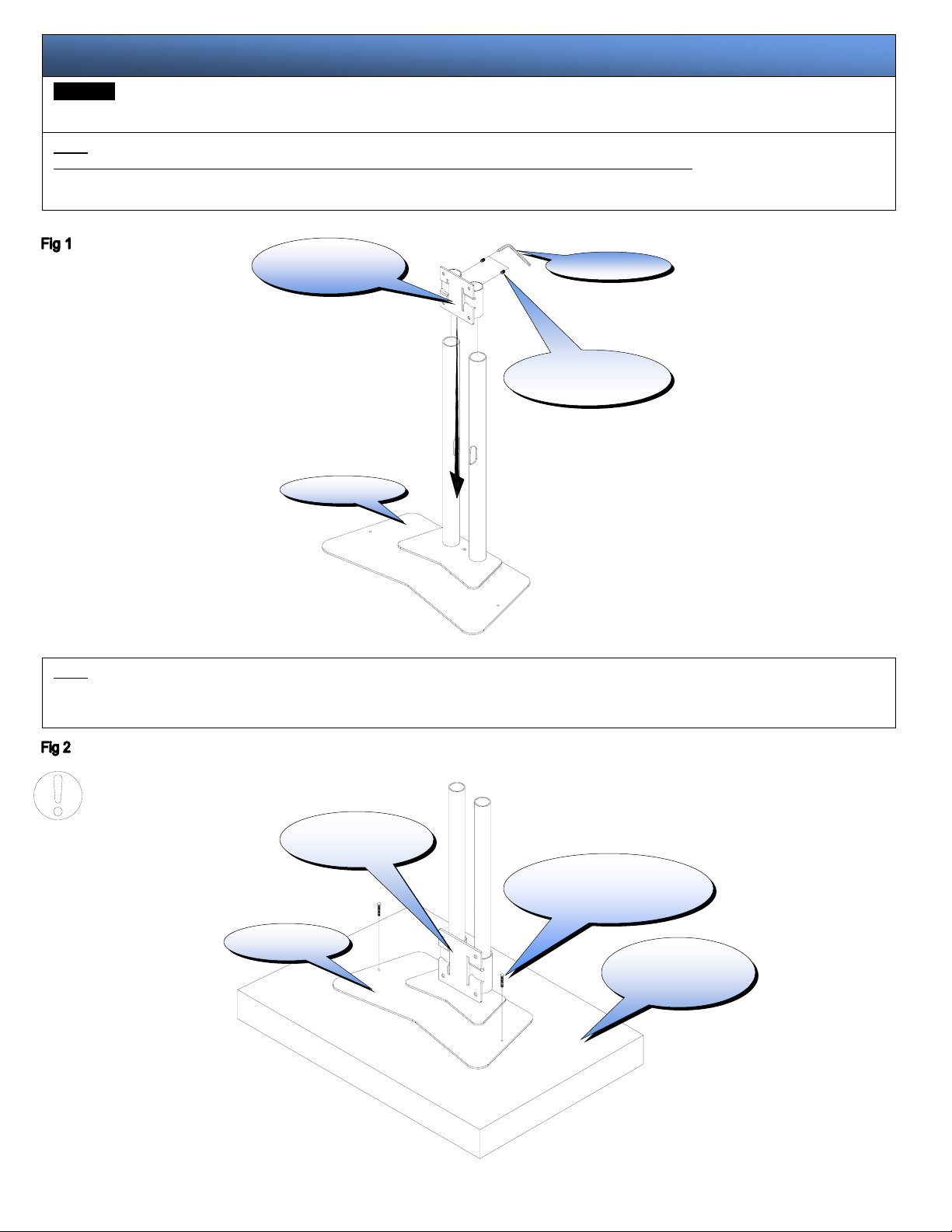
NOTE: Refer to the PSM or CTM series installation instructions to secure the mounting bracket to the plasma display.
Set the PSD-VHSA on the floor and loosely install the PP-SPA adapter over the tubes flat side facing out, attach the two (2) M8 x 10 socket head screws to the
adapter and slowly drop it to all the way until it touches the base. See figure 1.
Proper installation procedure by qualified personnel as outlined in the installation instructions must be adhered to. Failure to do so could
PP-SPA
ter
(2) M8 x 10 hex
head screws
Step 2
Choose the proper location for the PSD-VHSA and make sure that the location is weight suitable (see warnings). Using (commercially available) suitable hardware
depending on you installation environment the two holes found on the base may be used if needed to fasten the stand to the surface. See figure 2.
PP-SPA
ter
Suitable hardware
(commercially available)
Base
Suitable surface
(see warning)
- 5 -
Page 6
Measuring the plasma
Step 3
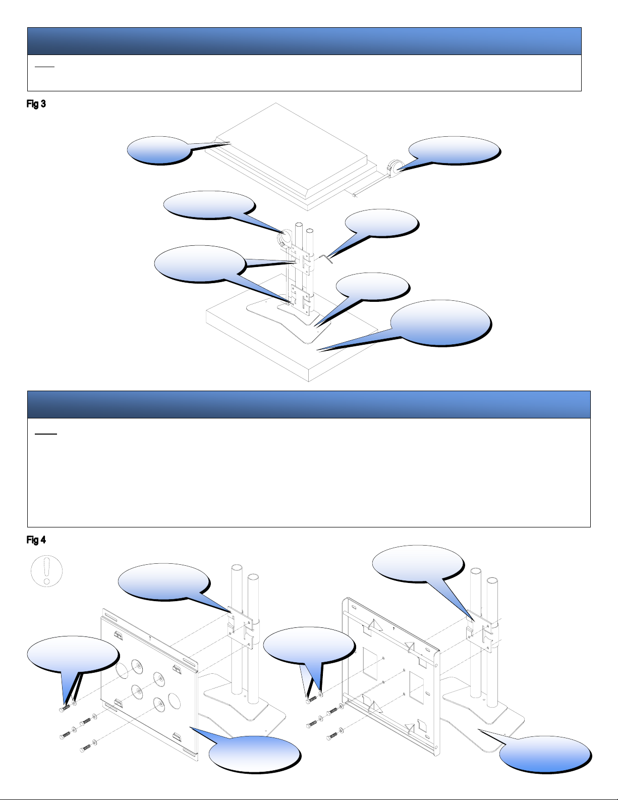
With the plasma display inverted measure and find the center of the plasma display. Measure from the top of the base plate to the center of the PP-SPA and lock the height by
tightening the two (2) M8 socket head screws (supplied) to the poles.
Plasma Measuring tape
Measuring tape
Allen wrench
PP-SPA
Adapter
Base plate
Suitable surface
(see warning)
Installing the wall plates
Step 4
CAUTION: The plasma display is vary heavy two people are required to lift the plasma and secure it to the stand.
The flowing diagrams show the CTM and PCM series systems.
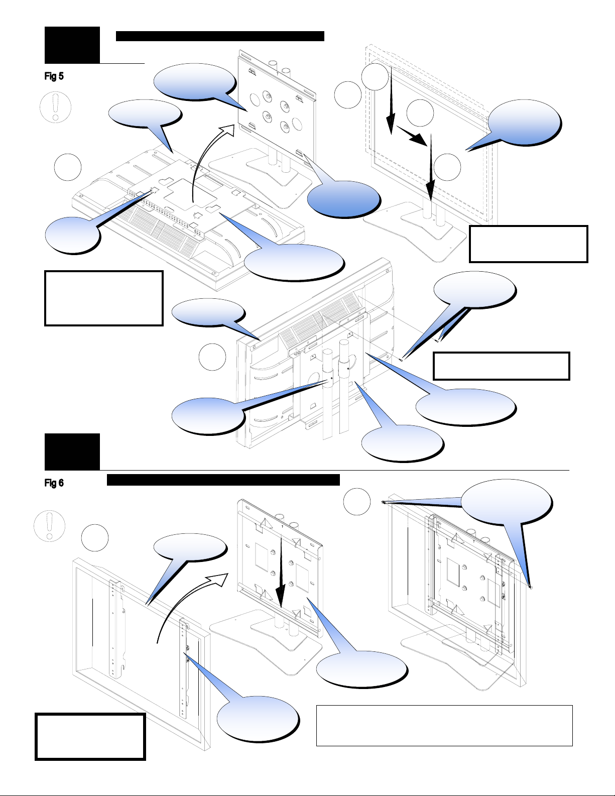
PSM-Series: Raise the plasma display with the mounting bracket secured to the plasma display and insert the four (4) tab openings from the PSM mount to the four (4) receiving tabs
found on the PDB-UWFB back plate slide the plasma down, right and down again to lock the mounts together. Make sure all tab openings are interlocked with the receiving tabs before
letting go of the plasma. Secure the brackets with the two (2) M6 x 12 (mm) Phillip screws (supplied).
CTM-Series: Raise the plasma display with the left and right brackets secured to the plasma and insert the bottom and top hooks from the mounting arms to the top and bottom rods found
on the CTM back plate. Secure the mounting arms with the two (2) M6 x 12 Safety knobs (supplied).
CAUTION: The safety knobs MUST be used failure to do so may result in damage to the plasma or personal injury. See fig 4,5,6.
PP-SPA
Adapter
PP-SPA
Adapter
M10 bolts & flat
washers
M10 bolts & flat
washers
- 6 -
CTM
Back plate
PDB-UWFB
Back plate
Page 7
prop
p
PSM
Series
A
(4) Tabs
openings
CAUTION: The plasma display is
vary heavy two people are
required to lift the plasma and
secure it to the stand
CTM
Series
1
Note: Make sure to recheck all
hardware for proper tightness
and security.
EXAMPLE PLASMA FOR ILLUSTRATION PURPOSES
PDB-UWFB
Back plate
Plasma
Receiving
(4) Tabs
Plasma mounting
bracket
.
Plasma
C
PP-SPA
Adapter
EXAMPLE PLASMA FOR ILLUSTRATION PURPOSES ONLY
Plasma
Mounting
brackets
Thank you for choosing PREMIER MOUNTS for your installation needs.
If you have any questions please contact PREMIER MOUNTS information is
shown on the front of this page.
B
2
CTM
Back plate
1
PDB-UWFB
Back plate
2
3
CAUTION: The mounts must have
all four (4) tabs engaged and
erly interlocked.
(2) M6 x 12
(2) M6 x 12
Phillip screws
Phillip screws
CAUTION: Secure the two (2) M6 x 12
screws to secure both brackets.
Philli
Plasma mounting
bracket
(2) M6 x 12
(2) M6 x 12
Safety knobs
Safety knobs
Mount
interlocking
- 7 -
 Loading...