

Page 1

PLASMA DISPLAY MOUNT MODEL
3130 E. Miraloma Ave. Anaheim, CA 92806 Phone: 800 368-9700 Fax: 800 832-4888
INSTALLATION MANUAL
VISIT US AT WWW.MOUNTS.COM
Page 2

,
Introduction
Plasma display manufacturers are constantly improving their products and introducing new ones. We are committed to keeping up with
them. That’s why we maintain close relationships with all major OEMs – to ensure that we have the latest information on new display
products coming to market. Our mounts are often available before the corresponding displays are even on sale.
Mounts are available in either flat or tilt versions, this versatile mount can be used for just about any application, including walls, stands,
carts
2
ceilings – even inside custom cabinets and other furniture applications.
Contents
NOTE: The following installation procedures indicate a wall structure installation. For installations other than wall mounting refer to installation instructions.
o Safety & precautions
o Mount diagrams
o Parts List
o Optional Adapters
o Installing the mounting bracket
o Installing the mount
o Electrical
o Securing the mount
o Additional security
NOTE: For installations other than wall mounting please refer to page 6. If installing the plasma display to the ceiling or floor stand please refer to its
installation instructions.
o Ceiling structure assembly drawing (pg 6)
Thank you for choosing PREMIER MOUNTS for your installation needs.
If you have any questions please contact PREMIER MOUNTS
Information is shown on the front of this page.
Page 3
p
y
jury
p
Safety & Precautions
WARNING: Safety precaution measures must be practiced at all times during the installation of this product. Use proper safety gear and tools for the
installations
rocedure to prevent personal injury or damage to the plasma displays or plasma mounts.
The wall or ceiling structure must be capable of supporting at least five (5) times the weight of plasma display.
If not, the wall or ceiling must be reinforced. Proper installation procedure by qualified personnel as outlined in the installations instructions
must be adhered to. Failure to do so could result in serious
ersonal injur
The entire installation instructions should be fully read and understood, including all of the safety symbols and safety precautions, before
beginning installation. The installation instructions should be read, understood and followed to prevent personal in
Keep these installation instructions in an easily accessible location for future reference.
or property damage.
Indicates that the power plug is to be disconnected from
the power outlet.
Contact Premier Mounts for any questions
Safety precautions must be taken at all times.
Warning and caution in general
A secured structure wooden stud wall must always support the weight or load of the plasma. Always confirm the center of the wood
stud before beginning the installation.
Do not install in locations where there is vibration, movement or danger of impact. Failure to do so could result in plasma cracking or
falling from the wall causing damage and injury.
Do not install near heater, fireplace, direct sunlight or air conditioning or any other source of direct heat energy. Failure to do so may
result in damage to the plasma television and could cause a risk of fire.
At least two qualified people should always perform the installation work. Injury and damage can result from dropping or mishandling
the plasma television.
Mounting structure recommended wood studs, solid-flat concrete, and reinforced metal studs. If installing the mount on other than
wood studs use (commercially available) suitable hardware.
3
Page 4
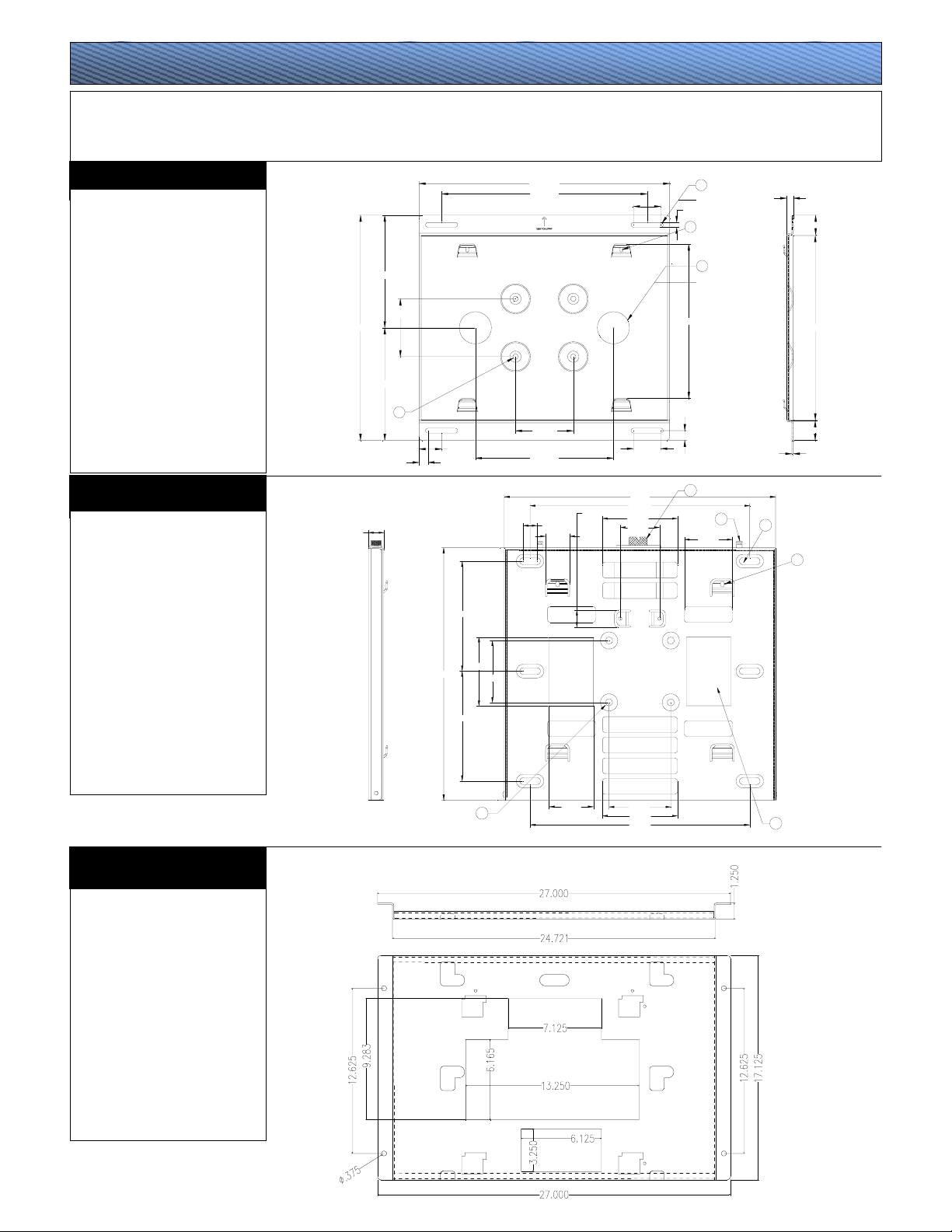
Mount Diagrams
Our PSM flat / tilt mounts are designed for wall or ceiling mounting, or it can mate with any of our popular carts, floor stands or wall arms.
The ultra slim plasma mount stands off the wall just enough for proper, OEM-specified ventilation, yet keeps the plasma close enough for a
clean, seamless look. It allows either vertical (portrait) or horizontal (landscape) display configuration.
UNIVERSAL FLAT MOUNT
PART#:
PDB-UWFB
MATERIAL:
12 (GA) CRS
COLOR:
Black powder coat
A.
Lag bolt access slot.
B.
Mounting points (4.5") used on
installations other than wall mounting.
C.
Access hole for power or cables.
D.
M6 security screw mounting points
used on installations other than flat
wall mounting.
UNIVERSAL TILT MOUNT
PART#:
PSB-TBP
MATERIAL:
12 (GA) P & O
COLOR:
Black powder coat
A.
Lag bolt access slot.
E.
Worm drive
F.
Locking pins
G.
Access hole for power or cables.
H.
Mounting points (4.5") used on
installations other than wall mounting.
8.750
4.500
17.500
8.750
b
1.750
0.688
1.125
8.000
5.000
18.500
4.500
8.000
19.500
16.000
4.500
10.750
1.000
1.750
1.250
2.125
2.125
19.771
16.000
5.460
2.865
0.375
d
12.000
0.750
e
a
Ø0.375 (x4)
c
Ø2.500
F
3.500
0.104
A
b
3.250
4.500
5.460
16.000
c
PSM SERIES MOUNT
PART#:
PDB-442
MATERIAL:
12 (GA) P & O
COLOR:
Black Powder coat
Note: The PDB-Series bracket mates
to the universal PDB-UWFB flat
mount and the universal PSB-TBP tilt
mount.
0.500
1.528
14.324
1.528
d
4
Page 5

(Op
Parts List
PSM-Mount
PSM-313
PSM-375
PSM-401
PSM-402
PSM-410
PSM-421
PSM-423
PSM-424
PSM-425
PSM-426
PSM-427
PSM-428
PSM-432
PSM-460
PSM-478
PSM-499
PSM-500
PSM-501
PSM-502
PSM-532
PSM-540
PSM-542
PSM-550
PSM-570
PSM-610
PSM-615
PSM-783
PSM-442
Standard hardware
QTY SIZE DESCRIPTION
6 (Tilt) – 4 (Flat) 5/16” Dia Lag bolts
1 PSM series mount
1 Flat / Tilt mount
2 M6 x 12 (mm) Phillip security
1 Installations instructions
1
screws
Used for additional security on
tilt mounts, mobile carts, floor
stands and ceiling mounts
Bubble level
PSM-Series Mounting hardware
QTY SIZE DESCRIPTION
6 M5 x 16 Phillip screws
4 M6 x 12 Phillip screws
6 M8 x 20 Phillip screws / Flat washers / Split washers
8 M6 x 12 Phillip screws
6 M5 x 16 Phillip screws / Flat washers / Split washers
6 M5 x 12 Phillip screws
6 M5 x 10 Phillip screws
6 M5 x 12 Phillip screws
8 M4 x 12 Phillip screws
8 M5 x 12 Phillip screws
6 M6 x 16 Phillip screws
8 M8 x 12 Phillip screws
6 M5 x 16 Phillip screws
4 – 4 M5 x 35 – M4 x 12 Phillip screws / Hex bolts
6 M6 x 12 Phillip screws
4 – 2 M5 x 50 / M10 x 25 Hex screws / Hex bolts / Flat washer
8 M5 x 20 Phillip screws / Flat washers / Split washers
6 M8 x 20 Phillip screws
6 M8 x 20 Phillip screws
• • •
6 M8 x 30 Phillip screws
2 M5 x 12 Phillip screws
2 M5 x 12 Phillip screws
6 M8 x 30 Phillip screws
6 M8 x 16 Phillip screws / Flat washers / Split washers
6 M8 x 10 Phillip screws
6 M6 x 12 Phillip screws
4 M8 x 30 Phillip screws / Flat washers / Fender washer / .5” nylon spacers
o Phillips screwdriver
o Drill gun
o Soft material or a blanket
o Pencil
o ¼" drill bit
o Level
o Measuring tape
o Wrench with a 1/2" socket
o Stud finder
o 1/4"-3/8" Toggler bolts: Used for hollow concrete block wall mounting.
o 5/16"-3/8" Wedge anchors: Used in solid brick or minimum-rated (3000psi) solid concrete.
TOOLS & SUPPLY NEEDED
tional) Installation Hardware
5
Page 6

(Optional) ceiling adapters
AST-2446: 1½" (Adjustable height suspension adapter) - Offering height adjustment in 1¼" increments, between 24" and 46"
(12" - 24", if you cut down), this suspension adapter mates with the single display swivel adapter and 1½" (NTP) pipe.
AST-2446/2: 2" (Heavy-duty adjustable height suspension adapter) - Offering height adjustment in 1¼" increments, between 24" and 46"
(12" - 24", if you cut down), this suspension adapter mates with the dual display swivel adapter and 2" (NTP) pipe.
PSD-S: 1½" (Single display swivel adapter) – This adapter could be mated with any two of out ultra slim flat or tilt plasma mounts to allow 360° swivel for a
ceiling installation. It works with 1½" threaded (NTP) pipe or AST-2446.
PSD-D: 2" (Dual display swivel adapter) - This adapter could be mated with any two of out ultra slim flat or tilt plasma mounts to allow 360° swivel for a ceiling
installation of two back to back displays. It works with 2" threaded (NTP) pipe or AST-2446/2.
PSD-PVW1: 1½" (Single display pole adapter) – Attach this adapter directly to any of the flat or tilt plasma mounts, and slide it over a 2" scheduled 40 steel
pipe, then secure at any height with two (2) tension-locked bolts.
PSD-PVW2: 2" (Dual display pole adapter) – Attach any two (2) of the flat or tilt plasma mounts back to back with this adapter, and slide it over a 2" scheduled
40 steel pipe, then secure at any height with two (2) tension-locked bolts.
A Plasma display
B PSM-Mount
C PSM-Hardware
(See chart on pg 5)
D M10 x 12 (mm) Hex
screws, flat washers
(4,4,8 Pack)
E PSB-UWFB Universal flat
mount
F M6 Security screws used
on tilt, ceiling, cart, floor
stand applications.
G PSB-TBP Universal tilt
mount
H AST-2446 adjustable
suspension post for single
display mounting or
AST-2446/2 adjustable
suspension post for dual
display mounting.
I PSD-S Single mounting
adapter
J PSD-D Dual mounting
adapter
K 1½" (NTP) For single
ceiling display installations
or 2" (NTP) For dual
ceiling installations
EXAMPLE PLASMA FOR ILLUSTRATION PURPOSES ONLY
Horizontal to vertical mounting
Horizontal to vertical mounting
Note: The M6 x 12 (mm) Security screws
Note: The M6 x 12 (mm) Security screws
must always be used for extra security.
could be used for additional safety.
Ceiling installation
assembly
6
Page 7

play
play
p
play
Installing the mounting bracket
WARNING : Proper installation procedure by qualified personnel as outlined in the installation instructions must be adhered to. Failure to do so could
result in serious personal injury and possible damage to the plasma display.
Step 1
CAUTION: The plasma displays are fragile and heavy. At least two (2) qualified personnel are strongly recommended for the installation of this product.
Invert the plasma display and set it on a soft, flat surface to prevent any damage to the plasma display. See fig 1.
EXAMPLE PLASMA FOR ILLUSTRATION PURPOSES ONLY
Top of the plasma
dis
Inverted plasma
dis
Soft and flat surface
blankets, foam, cloth
etc.
Bottom of the
lasma display
Step 2
CAUTION
Locate the mounting points found on the back of the plasma chassis, align the mounting holes from the mounting bracket to the holes on the chassis. Arrow found
on the PSM mount must always be pointing to the top of the plasma display before securing it to the chassis. Secure the mounting bracket to the plasma display by
using the hardware specified on the parts list. CAUTION
WARNING: Do not use the drill gun to secure the screws to the plasma display. A Phillips head screwdriver is preferred.
: The plasma displays are fragile and heavy. At least two (2) qualified personnel are strongly recommended for the installation of this product.
: Do not over tighten the mounting hardware. See fig 2.
PSM-series
mount
Mounting hardware
(see chart on pg 5)
Inverted plasma
dis
7
Page 8

A
V
g
Installing the mounts
Step 3
Securing the flat mount
: The plasma displays are fragile and heavy. At least two (2) qualified personnel are strongly recommended for the installation of this product.
CAUTION
All plasma models vary depending on the manufacturer and some are centered and others are not. Please verify that your plasma mounting points from the back of the chassis are
centered before installing the universal back plate.
Select the area where the plasma will be installed and make sure it can support the weight standards (see warning on page 3). Locate the 16" wood stud centers behind the wall using
a (commercially available) stud finder and mark the center of the studs when found. Set the mounting bracket to the wall and mark the desired height by marking the center of the
universal flat mount.
Note: Same installation process applies to the PSM-Tilt series. See fig 3.
Note: Pre drill before the securing the
5/16" la
bolts.
Caution: Do not over tighten the 5/16" lag bolts
Wall structure
Desired height
marking
Universal flat
mount
16"
Stud centers
marking
djusting the
mount
CENTER
Wood studs behind
the wall structure
floor floor
OF
IEWING
HEIGHT
8
Page 9

y
Securing the flat mount or tilt mount
To determine the desired viewing height, use the center slot opening in the wall mount as a center reference for the plasma television when mounted. Once the height is determined,
use the bubble level to insure that the bracket is level. Next, using a pencil, mark the four (4) lag bolt slot openings on the mounting bracket. Before continuing, confirm the marks are
located on the center of the studs.
Drill 1/4" pilot holes on the four (4) markings on the wall. Raise the universal flat or universal tilt bracket and have someone hold it in place (arrow side away from the wall and
pointing up). Put the lag bolt through the flat washers. Screw the lag bolt through the upper left slot opening into the 1/4" pilot hole. Confirm that the wall mount is still leveled and then
screw a lag bolt to the upper right side slot opening into the 1/4" pilot hole. Then install the remaining two lag bolts tightly into the wall studs in the lower left and right slot openings on
the wall mount.
Lateral movement of approximatel
1½" for final positioning is now possible. Make any positioning changes then secure the lag bolts. See fig 4.
Flat washers
Lag bolts
Universal flat
mount
Drill gun with a
1/4" drill bit
Marking on wall
Access holes
Wall structure
Wood studs behind
the wall structure
floor
floor
Electrical
Step 4
All electrical wiring components should be installed at this time to ensure that the plasma display has enough power sources.
9
Page 10

Securing the mount
A
p
Step 5
Warning: The plasma display is heavy and 2 people are needed to lift and install it. Failure to do so could result in serious personal injury.
Before placing the plasma on the wall recheck all hardware for proper tightness and security. Before installing, become familiar with the way the plasma mount attaches to the wall
mount. Align the four (4) tab openings to the four (4) receiving tabs on the flat back plate. When all four (4) the tabs are aligned slide the plasma down, right and down again to lock the
mounts together. Make sure all (4) tab openings are interlocked with the receiving tabs before letting go of the plasma. See fig 5.
Caution: The plasma display is heavy and 2 people are needed to lift and
install it. Failure to do so could result in serious personal injury.
PSM-series
mount
Tab openings
Universal flat
mount
Locked tab
Securing tabs
lign the tabs and
push the plasma
as shown on
arrows to lock in
Caution: All four (4) receiving tab openings from the
mounting bracket must be locked to the tabs found on
the flat back plate before letting go of the plasma
display. See the diagram on the left to see the
interlocked tab.
Plasma display
lace
Plasma display
Wall structure
Wall structure
Additional security (Does not apply to flat wall mounting)
Step 6
For additional security gradually tilt the bracket forward using a Phillips screwdriver. Secure the two (2) M6 x 12 (mm) Phillips screws (screws) see fig 6. Do not over tighten the screws.
Position the bracket to the desired angle.
10
Page 11

HARDWARE NOTICE
PANASONIC MODELS
PACK 2
USED ON THE FOLLOWING
MODELS
42" TH42PWD4UY, TH42PWD4EX,
PT42P1, 42PD2, TH42PWD3U,
TH42PHD5U, PT42PD4, PT42PHD4P,
TH42PWD5UY, TH42PW5UZ,
TH42PWD6UY
50" TH50PHD3U, PT50PD3P,
TH50PHD3E, TH50PHW3, TH50PD4,
TH50PHD5UY, 50PHW5UZ
PACK 28
USED ON THE FOLLOWING
MODELS
42" TH42PA20UP
If you have any questions contact
Page 12

NEW HARDWARE APPLIES TO
PLASMA MODELS:
Fujitsu 50" & 61"
5001, 5002, PDS6101, PDS6001,
PDS6002,P50XCA11UH
P50XCA10WH, P50XCA10HA
P50XCA10UH,P50XCA11WH
P50XCA11AH, P50XCA12WH
P50XCA12EH, P50XCA12AH
P50XCA12UH
Panasonic 42", 50"
TC42P1, PT42PD3P, PT42PD1P,
TC42P1F, PT37P1, TH42PWD3,
TH37PWD4UZ, TH42PWD4UY,
TH42PWD4EX, PT42P1, 42PD2,
TH42PWD3U, TH50PHD3U,
PT50PD3P, TH50PHD3E, TH50PHW3
Runco 42"
PL42cx,
Toshiba 42", 50"
50HP81, PD42W, PD42W1
ViewSonic 42"
VPW420,
Dwin 50"
HD50
JVC 50"
GDV500PZU
N E W H A R D W A R E
NOTICE APPLIES TO PCM (REV 8)
CTM (REV 8) / PSM / PRM MOUNTS.
Nylon sleeves
½" Nylon spacers
ASSEMBLED
CAUTION!
The nylon sleeves and ½” nylon spacers must ALWAYS be used in order to install plasma bracket on to the
plasma. Failure to do so will result in damaging the plasma internally. This application is required by the plasma
manufacture.
 Loading...