

Page 1
Personal Viewing System
Assembly and Operation Manual
PVS-15
Cardio Theater Holdings, Inc.
21420-D NW Nicholas Court #12-13
Hillsboro, OR 97124
(800) 776-6695
(503) 645-8881
www.cardiotheater.com
Page 2

TABLE OF CONTENTS
Parts List…………………………………...Page 2
Stand Assembly………………..………… Page 3-4
DVD Player Assembly………..…………..Page 5-7
LCD Screen Assembly………………..….Page 8-9
Mounting Screen Controller…………..….Page 10
Programming TV Channels………….…..Page 11
Cable Management……………………….Page 12
RF Distribution…………………………….Page 13
Specifications…………………………….. Page 14
Warranty……………………………………Page 15
Technical Support…………………………Page 16
1
Page 3

Parts List:
Master Set Up Package
1 Master IR Remote Control
1 Operations Manual
Screen Controllers (1 for each Screen)
1 Neoprene Mounting Pad (1 for each controller)
1 DVD Player Master IR Remote (Optional)
Screen Box
1 15 inch LCD Screen
1 AC Adapter
1 Adapter Power Cord
1 LCD Back Cover
1 Controller Cable
1 LCD Screen Hardware Package
4 Wire Ties
Stand Box
2 Stand Feet
1 Base Cross Bar
1 Lower Vertical Tube
1 Upper Vertical Tube (Short or Long Model)
1 Base Cover
1 Coax / Power Cable
8 Hex Screws
DVD Player Box (Optional)
1 DVD Player
1 12 Volt Power Cable
1 Audio / Video RCA Patch Cord
DVD Bracket (Optional)
1 Long or Short Bracket (as ordered)
1 Back Cover (Short Version Only)
1 DVD Hardware Package
2
Page 4
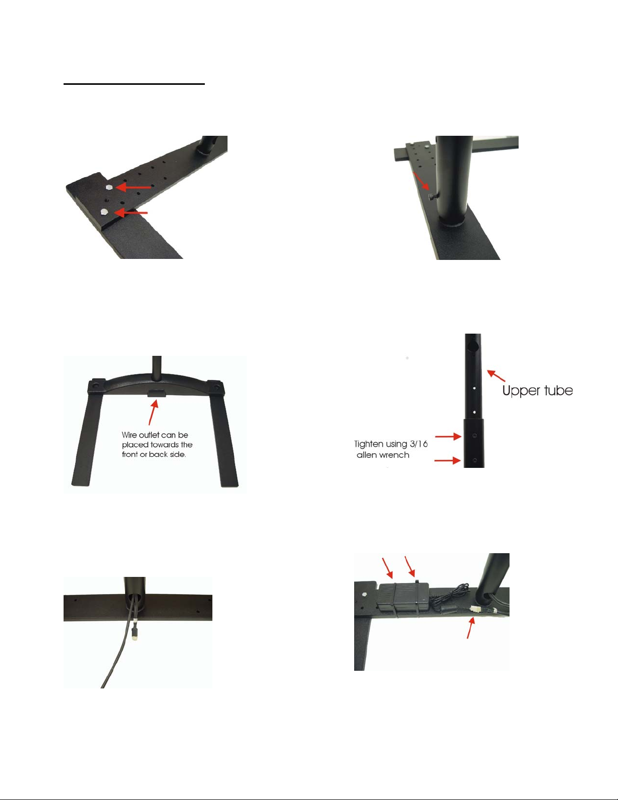
Stand Assembly
Step 1
Determine width of stand feet in relation to the
cardio equipment. Use a 7/16 wrench to secure
2 hex screws per leg.
Step 3
Step 2
Insert lower vertical tube over center stub
and hand install one 3/16 Allen head screw a
few turns into vertical tube. Do not tighten
at this time. (Clearance needed for Wires)
Step 4
Insert plastic base cover over lower vertical
tube. Do not fasten down at this time.
Step 5
Insert cable assemblies through upper tube
opening and bring out lower tube hole as shown.
Insert upper curved tube into lower tube. Do
not install bolts until step 5 is performed,
then adjust upper tube to desired height and
install two Allen screws as shown above.
Step 6
Mount power supply with 2 wire ties to the
3
base assembly. Plug power supply connector
into cable previously installed down vertical
tube.
Page 5
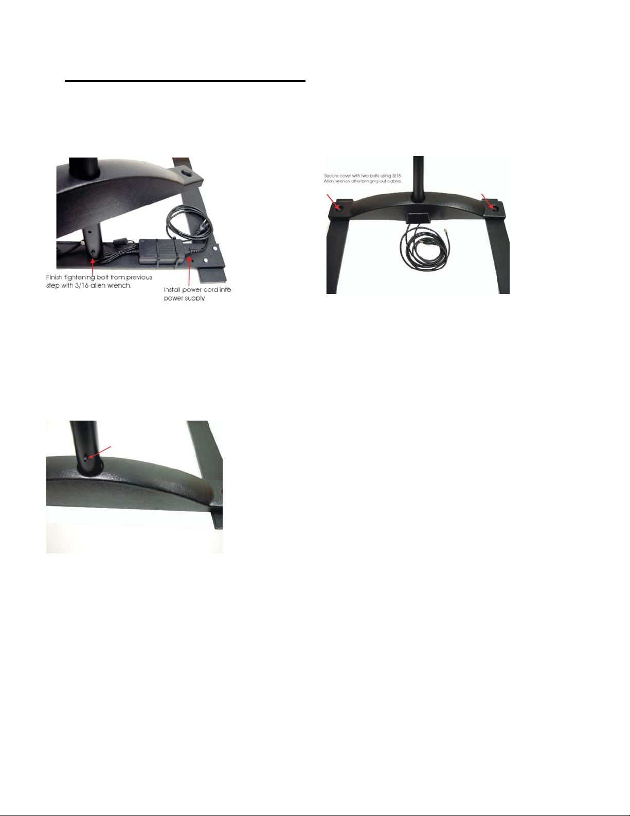
Stand assembly- continued
Step 7
Step 8
Route coax and AC power plug to center
Opening of base cover and make sure to tighten lower
bolt before installing cover.
Step 9
Install last remaining Screw in upper tube
Assembly and double-check all Fasteners for
Tightness.
With cables properly placed in cover slot, secure
base cover with 2 Allen head screws provided.
4
Page 6
DVD Player Assembly
NOTE: Skip to Page 7 if not installing DVD Player
Important: There are two models of DVD brackets.
Short DVD Bracket Long DVD Bracket
For S Model Stand For L Model Stand
1: Run supplied Audio Video cable and DVD 12 Volt Power cable from
opening at top of stand out through large round hole in upper tube of
stand.
5
Page 7

2: Pull Audio/Video and 12 Volt Power cable wires through hole in DVD bracket
and attach bracket to stand with 2 hex screws provided.
IMPORTANT: When attaching Short Version, confirm that the large
square opening on the rear of the bracket is positioned on the right
side of the stand tube as shown.
Short Version Long Version
3: Plug Audio Video cable into the Video & Audio “Output” on the rear of the
DVD player.
4: Plug 12 Volt Power cable into 12 Volt input on rear of DVD player.
5: Remove two security screws from top of DVD player.
Attach DVD player to bracket with 4 Phillips screws provided.
Short Version Long Version
Attach back cover with 4 Phillips
screws provided.
6
Page 8

6: Connect DVD 12 Volt Power cable to main Coax / Power wire coming
through top of stand.
7: Connect the Video cable coming from the DVD player “Output” to the connector labeled
“Video Y” on the back of the monitor and the cable going from the DVD players audio
outputs to “Audio Left & Right” input on the back of the monitor.
7
Page 9

LCD Screen Assembly
1. Attach pivot assembly to back of LCD monitor using upper two mounting holes as
shown in figure 1. Leave out the lower two mounting screws until after all wiring is
installed onto back of monitor.
2. Install monitor assembly onto upper stand tube using (3) M4 X 10mm socket head
cap screws as shown in Figure 2
3. Install power connector from harness that was installed into stand assembly
earlier, to input on back of monitor labeled “DC12V” as shown in figure 3.
4. Plug Screen Controller cable from stand harness to telephone type RJ45 plug on
back of monitor. (Figure 4)
Figure 1 Figure2
Figure 3 Figure 4
8
Page 10

LCD Screen Assembly (continued)
5. Remove slip-on antenna connector from monitor by pulling straight down on
connection (Figure 5).
Screw slip-on connector onto coax cable and then push assembly back into the
monitor’s antenna connector. (Figure 6)
6. Attach Back Cover plate using 2 M4 x 10mm black screws. (Figure 7)
Note: Before securing back cover, confirm that all cables connected to
LCD screen have sufficient slack for tilting the monitor and are not that
they are not intertwined.
Figure 5 Figure 6
Figure 7
7. Pull excess wires through hole of Lower Vertical Tube on stand and conceal inside bottom plastic Base Cover.
8. Plug 110AC power cord into AC outlet.
9. Plug screen control cable into controller.
10. Power On LCD screen and test functions
9
Page 11

Mounting Screen Controller
CNTE-4 CNTE-16
1. Remove backing from neoprene mounting pad and place either vertically
or horizontally around equipment handrail as appropriate as shown below.
2. Insert two nylon wire ties (provided) through the bottom holes in the
mounting bracket on the rear of the Screen Controller.
3. Attach wire ties as tightly as possible around the horizontal or vertical bar so the
controller can’t be rotated. This is very important to keep moisture out of the
controller and to keep from damaging the electronics inside unit.
ΝΟΤΕ: Do not place controller where it would interfere with the cardio unit
controls or display panel. The Screen Controller mounting bracket may
be removed with pliers and mounted with Super Lock Velcro to any flat
surface.
10
Page 12

Auto Programming TV Channels
The following requires the LCD Screen Master IR Remote Control Unit
1. Press menu button on Master IR Remote.
2. Scroll Down to “Install” then press “Select”.
3. Select “Auto Search” and press “Select”.
4. Select Cable, HRC or Air (Check local cable company for HRC)
5. Note: Programming may take up to 3 minutes.
Manually Add or Erase Channels:
1. Manually select channel using Master IR Remote.
2. Press menu button on Master IR Remote.
3. Scroll Down to “Install” and then press “Select”.
4. Scroll to “Store/Clear”.
5. Select “Store” or “Clear”
6. Choose next channel and repeat.
11
Page 13

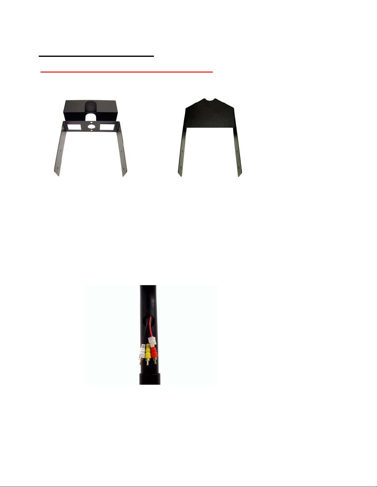
Cable Management System
The Optional Cable Management System is used to cover the antenna cable and
power cords that run between the individual stands. It consists of a metal bracket
that connects to the bottom of the monitor stand and a plastic two-channel
extrusion that can be cut to length with common hand tools.
5 foot Cable Management extrusion.
Cable Management Bottom view of bracket
Mounting bracket mounted with four screws
Installation Instructions
Step 1
After monitors are mounted to stands and the proper spacing between equipment
has been determined, measure distance between stands and cut Cable
Management extrusion to length.
Step 2
Remove Allen Head screw from plastic bottom cover of stand. Place mounting
bracket over same hole and re-install the Allen Head screw.
Step 3
Place Cable Management extrusion into end of bracket and install 4 self tapping
screws, two on each side of bracket.
Repeat on opposite side of extrusion.
12
Page 14

RF Distribution
Below is a diagram of a typical install. Please note that the tap values are dependant on
having a 35 db signal at the output of the signal amplifier. It is best to use a quality
amplifier that has a variable output so that you can adjust it to match 35 db even if your
input is either lower or higher.
These tap values and db readings are based on RF theory.
13
Page 15

Specifications:
15” Color LCD Monitor
Visible Screen Size 304.1(H) X 228.1(V)
Pixel Range 0.297(H) X 0.297(V)
Type a-si TFT Liquid Crystal Display
Visual Angle upper 55’/lower 65’, left 70’/right 70’
Horizontal Frequency 31~60 KHz(Auto Set)
Vertical Frequency 56~75 Hz(Auto Set)
Display Color 16.2M Color
Input/Video Signal Analog 0.714Vp_p Positive(75ohm)
TV Color System PAL,SECAM,NTSC
Channel Memory 100 Channel—PAL System
Receiving Channel 181Ch (113ch CATV)—NTSC System
Video Input Color PAL/SECAM/NTSC
Power Adaptor Input :100~240V @.1A max – Output: 12Vdc@3A
Operating Temperature 0’C~40’C
Conditions Humidity 10%~85%
DVD Player (Optional) Please see DVD Manual in DVD Box
14
Page 16

Warranty
Cardio Theater™ warrants the Personal Viewing System to be free from defects
in material and workmanship for the following period of time from date of
shipment, provided that the products have not been subject to mechanical,
electrical, or other abuse or modifications.
Cardio Theater LCD Screen 1 Years Parts & Labor
Cardio Theater Screen Controller 1 Year Parts & Labor
Quick Change Headphone Jack 90 Days (from original installation)
Should the LCD Screen, DVD Player or Controller be deemed defective by
Cardio Theater, a return authorization number will be issued. Cardio Theater
will not accept returns without a return authorization number. Cardio
Theater reserves the right, at their option, to repair or replace the equipment after
verification of defect.
Equipment that fails after the warranty period expires will be repaired at the
current price of part and labor after authorization from the customer. Repairs are
warranted for 90 days.
This warranty is in lieu of all other warranties expressed or implied.
FCC Compliance Statement
NOTE: This equipment has been tested and found to comply with the limits for Class B digital device, pursuant
Part 15 of FCC Rules. These limits are designed to provide reasonable protection against harmful interference.
This equipment generates, uses and can radiate radio frequency energy and, if not installed and used in
accordance with the instructions, may cause harmful interference to radio communications.
However, there is no guarantee that interference will not occur in a particular installation. If this equipment does
cause harmful interference to radio or TV reception, please contact Cardio Theater Inc. for trouble shooting
guidance.
DOC Class B Notice
This digital apparatus does not exceed Class limits for radio noise emission as set out in the Radio Interference
Regulations of the Canadian Department of Communications.
The user is cautioned that changes or modifications not expressly approved by
the manufacturer of the equipment could void the user’s authority to operate the
equipment.
WARNING: To Prevent Fire Or Electrical Shock, Do Not Expose This Appliance
To Rain Or Moisture.
15
Page 17

Technical Support
Technical Support Numbers
Telephone 1-800-776-6695
Technical Support Hours:
6:00 AM to 5:00 PM Monday through Friday PST.
Write To:
Cardio Theater Holdings, Inc.
21420-D NW Nicholas Court #12-13
Hillsboro, OR 97124
Notice
Due to continuing advancements in technology, Cardio Theater Holdings, Inc.
reserves the right to make changes in hardware, packaging, and any
accompanying documentation without prior written notice.
Cardio Theater PVS and Cardio Theater Quick Change Headphone Jack are
registered trademarks of Cardio Theater Holdings, Inc.
© 2003 Cardio Theater Holdings, Inc., all rights reserved
16
Page 18

17
 Loading...