

Page 1

Low Impact Treadmill
Owner’s Manual
page 1
Page 2

IMPORTANT SAFETY INSTRUCTIONS
When using an electrical appliance, basic precautions should always be taken,
including the following:
• Read all instructions before using the M9.55 treadmill. These instructions
are written to ensure your safety and to protect the unit.
Before beginning any fitness program, you should obtain a complete physical
examination by your physician.
Il est conseillé de subir un examen médical complet avant d’entreprendre tout
programme d’exercise. Si vous avez des étourdissements ou des faiblesses,
arrêtez les exercices immédiatement.
DANGER
To reduce the risk of electrical shock always unplug the treadmill from the
electrical outlet immediately after using and before cleaning.
WARNING
To reduce the risk of burns, fire, electric shock, or injury to persons, take the
following precautions:
• When it is plugged in, do not leave the M9.55 unattended. Unplug the
treadmill from the power source when it is not in use, and before putting on
or taking off parts.
• Do not allow children on or near the M9.55 treadmill.
• Use the M9.55 only for its intended purpose as described in this manual. Do
not use accessory attachments that are not recommended by the manufacturer—such attachments might cause injuries.
• Never operate the unit if it has a damaged cord or plug, if it is not working
properly, if it has been dropped or damaged, or dropped in water. Return
the M9.55 to a service center for examination and repair.
• Keep the power cord and plug away from heated surfaces.
• Never block the air vents while operating the treadmill. Keep the air vents
clean and free of lint, hair, or anything that might impede the free flow of air.
• Never drop or insert objects into any opening. Keep hands a way fr om mo ving
parts.
• Do not use outdoors.
• Do not operate where aerosol (spray) products are being used or where
oxygen is being administered.
• When the treadmill is not in use, disconnect the unit by turning the power
switch to the OFF (O) position, then remove the power plug from the wall
outlet.
IMPORTANT SAFETY INSTRUCTIONS
WARNING
page 2
Connect the M9.55 to a properly grounded outlet only. The M9.55 treadmill must
be connected to a 20 amp dedicated circuit. See
5.
Grounding Instructions
on page
Page 3

Personal Safety
When using the treadmill, take the following precautions:
• Do not allow children on or near the treadmill. Do not leave children unsupervised around the treadmill.
• Assemble and operate the treadmill on a solid, level surface. Locate the treadmill a
few feet from walls or furniture. Keep the area behind the treadmill clear.
• Maintain the treadmill in good working condition. (Refer to the Maintenance
section.) Run through a check list prior to each use. Make sure that all fasteners
are secure and the belt is clean and running smoothly.
• Turn OFF (O) and unplug the treadmill when adjusting or working near the rear roller.
Do not adjust the running belt when someone is standing on the unit.
• Keep all electrical components, such as the motor, power cord, and I/O switch, a way
from liquids to prevent shock. Do not set anything on the handrail, display console, or
hood. Place liquids in the appropriate receptacles.
• The security clip should be attached at waist level prior to beginning a workout. A
cord connects the security clip to the red STOP button on the console. If you
encounter difficulties, the running belt can be stopped by pulling on the cord.
• To help prevent unauthorized use, the M9.55 is equipped with password protection. The password involves entering three keys in sequence. Refer to Entering a
Password on page 19.
• Wear proper exercise clothing and shoes for your workout—no loose clothing.
Do not wear shoes with heels or leather soles. Check the soles of your shoes
and remove any dirt and embedded stones. Tie long hair back.
• Keep all loose clothing and towels away from the running surface. Tie long hair
back. The running belt will not stop immediately if an object becomes caught in
the belt or rollers.
• Use care when getting on or off the treadmill. Use the handrail(s) whenever
possible. Step onto the running belt when the speed is at 1 mph (1.5 kph). Never
step off the treadmill while the running belt is moving.
• Before the running belt begins moving (prior to your workout), and after it stops (at
the end of your workout), straddle the belt by placing your feet firmly on the right
and left side platforms.
• Never turn ON the treadmill when someone is standing on the machine.
• Keep your body and head facing forward. Never attempt to turn around on the
treadmill when the running belt is moving.
• Do not rock the unit. Do not stand on the handrails, display console, or hood.
• Do not attempt to service the treadmill yourself other than the assembly and
maintenance instructions found in this manual.
• Do not overexert yourself or work to exhaustion. If you feel any pain or abnormal
symptoms, stop your workout immediately and consult your physician.
Precor treadmills are designed for the enjoyment of the serious runner as well as
the dedicated walker. By following the above precautions and using good common
sense, you will have many safe and pleasurable hours of healthful exercise with
your Precor treadmill.
Precor Heart Rate Option—Safety Guidelines
The Precor Heart Rate Option was created and designed exclusively for Precor
products. The equipment is extremely sensitive—you should use the heart rate option
page 3
Page 4

with this in mind and take time to read the guidelines found on page 39.
RFI — Radio Frequency Interference
Federal Communications Commission, Part 15
The M9.55 treadmill has been tested and found to comply with the limits for a Class B
digital device, pursuant to Part 15 of the FCC Rules. These limits are designed to
provide reasonable protection against harmful interference in a residential installation. The M9.55 treadmill generates, uses, and can radiate radio frequency energy
and, if not installed and used in accordance with the owner’s manual instructions,
may cause harmful interference to radio communications. However, there is no
guarantee that interference will not occur in a particular installation.
If the M9.55 treadmill does cause harmful interference to radio or television reception, which can be determined by turning the M9.55 treadmill OFF and ON, you are
encouraged to try to correct the interference using one or more of the following
measures:
• Reorient or relocate the receiving antenna for your TV, radio, VCR, etc.
• Increase separation between the treadmill and the receiver (TV, radio, etc.).
• Connect the treadmill into a different power outlet—on a dedicated circuit
different from the one used by the receiver (TV, radio, etc.). No other appliance
should be plugged into the same power outlet that the treadmill is connected to.
• Consult an experienced radio/TV technician for help.
CAUTION
Per FCC rules, changes or modifications to the
treadmill not expressly approved by Precor, could
void the user’s authority to operate the equipment.
page 4
Canadian Department of Communications
This digital apparatus does not exceed the Class B limits for radio noise emissions
from digital apparatus set out in the Radio Interference Regulations of the Canadian
Department of Communications.
Le présent appareil numérique n’émet pas de bruits radioéélectriques dépassant les
limites applicables aux appareils numériques de la class B prescrites dans le
Règlement sur le brouillage radioélectrique édicté par le ministére des Communications du Canada.
European Applications
This product conforms to the requirements of the European Council Directive 89/336/
EEC, Electromagnetic Compatibility and has been tested to the following standards:
EN55022, Limits & Methods of Measurement of Radio Interference, Information
Technology Equipment (Class A).
EN50082-1, Generic Immunity Standard for Residential, Commercial and Light
Industrial Products (Class A).
This product additionally conforms to the requirements of the European Council
Directive 73/23/EEC, Low Voltage Directive and has been tested to the following
standard:
IEC 335-1, Safety of Household and similar Electrical Appliances.
European Applications - 240 Volt Units Only
This product has been tested to the requirements of EN55022, “Limits & Methods of
Measurement of Radio Interference, Information Technology Equipment.” Per that
standard, the M9.55 treadmill is a Class B product. In a domestic environment, these
products may cause radio interference, in which case the user is responsible to take
adequate measures to alleviate the interference.
Page 5
Safety Approval
When identified with the ETL-c logo, the treadmill has been tested and conforms to
the requirements of CAN/CSA-E-335-1/2-94, Safety of Household and Similar
Electrical Appliances.
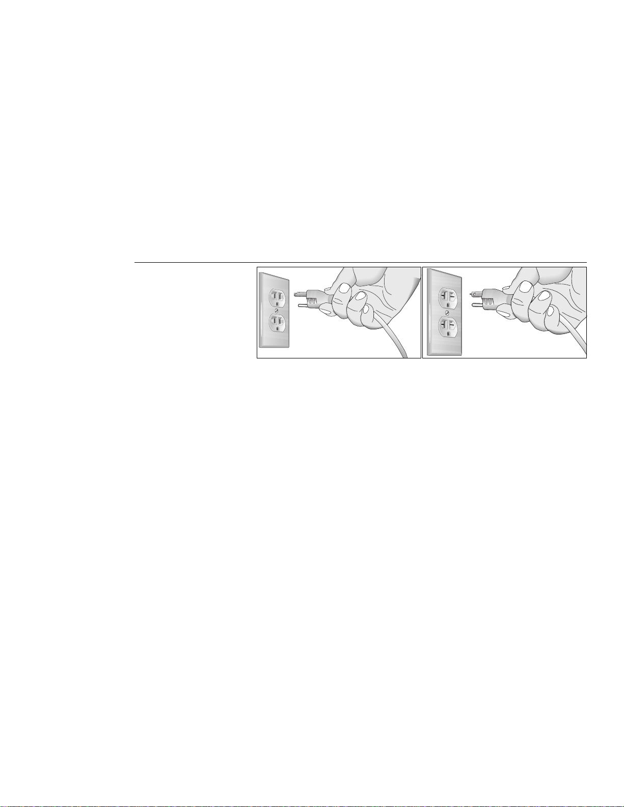
Grounding Instructions
The M9.55 Low Impact Treadmill must be grounded. If it should malfunction or break
down, grounding provides a path of least resistance for electric current which
reduces the risk of electrical shock. The treadmill is equipped with a power cord
having an equipment-grounding conductor and a grounding plug. The plug must be
inserted into an appropriate outlet that is proper ly installed and grounded in accordance with all local codes and ordinances. If you do not follow these
Instructions
Diagram 1
Correct power outlet for
U.S. Markets: 15 amp
120-volt and 240-volt plugs.
Grounding
, you could void the Precor limited warranty.
120-volt grounding plug 240-volt grounding plug
DANGER
Improper connection of the equipment-grounding conductor can result in a risk of
electric shock. Check with a qualified electrician or service person if you are in doubt as
to whether the treadmill is properly grounded. Do not modify the plug provided with the
treadmill—if it doesn’t fit the outlet, get a proper outlet installed by a qualified technician.
120V Units Designated for U.S. Markets
The M9.55 treadmill must be connected to a 20 amp
nominal rating of 120-volts. The treadmill’s grounding plug looks like the plug illustrated in Diagram 1. The power outlet must have the same configuration as the plug.
No adapter should be used with this product.
240V Units Designated for U.S. Markets
The M9.55 treadmill must be connected to a 20 amp dedicated circuit having a
nominal rating of 240-volts. The treadmill is factory-equipped with a specific power
supply cord to permit connection to a proper electric circuit. Make sure that the
treadmill is connected to an outlet having the same configurations as the plug. See
Diagram 1. No adapter should be used with this product. If the treadmill must be
reconnected for use on a different type of electrical circuit, the reconnection must be
made by qualified service personnel.
dedicated
circuit having a
ATTENTION: Haute Tension
Débranchez avant de réparer
page 5
Page 6

Table of Contents
Important Safety Instructions............................................................. 2
Personal Safety ................................................................................. 3
Precor Heart Rate Option - Safety Guidelines .................................. 3
RFI — Radio Frequency Interference ................................................ 4
European Applications ...................................................................... 4
Safety Approval ................................................................................. 5
Grounding Instructions ...................................................................... 5
Before Y ou Begin ..............................................................9
1
Obtaining Service .............................................................................. 9
Unpacking the M9.55 Low Impact Treadmill ...................................... 9
Optional Equipment ........................................................................... 9
Hardware Kit......................................................................................10
Acquiring the Appropriate Tools ........................................................10
Setting Up the Treadmill.................................................11
2
Installation Requirements.................................................................. 11
Assembly Instructions ....................................................................... 11
Turning the Unit ON and OFF ............................................................17
Checking the Alignment of the Running Belt.....................................18
Using the M9.55 Treadmill..............................................19
3
Safety Features .................................................................................19
Using the Security Clip ......................................................................19
Entering a Password .........................................................................19
Workout Tips......................................................................................20
Quick Steps to Working Out ..............................................................21
Cooling Down After Your Workout......................................................22
Pause, Cool Down, Workout Summary, and Exit Features ...............23
The M9.55 Display ..........................................................25
4
Features on the Display Console ......................................................25
Changing User Display Fields ...........................................................26
Deleting Workout Statistics................................................................27
Smart Rate
Heart Rate Display ............................................................................28
Upper Display ....................................................................................28
Lower Display ....................................................................................28
Keys on the Display Console.............................................................29
Keypad Tips.......................................................................................30
®
.......................................................................................28
Programming the M9.55 Treadmill ................................32
5
Selecting a U.S. Standard or Metric Display......................................32
Securing the Treadmill with a Password............................................ 3 3
Creating a User Name.......................................................................33
Viewing the Odometer, Hours of Use,
Software Version, and Error Log........................................................34
page 6
Page 7

The M9.55 Courses.........................................................35
6
Using the POLAR® Equipment ......................................41
7
Maintenance....................................................................42
8
Course Features and Course Descriptions .......................................35
Utilizing the Smart Rate
Utilizing Heart Rate Interactive Capabilities ......................................39
Heart Rate Course ............................................................................40
Wearing the POLAR® Chest Strap ....................................................41
Storing the POLAR
Cleaning the Equipment ....................................................................42
Aligning the Running Belt ..................................................................43
Servicing the Treadmill ......................................................................43
Long Term Storage ............................................................................43
Exploded Views .................................................................................44
Warranty Card ...................................................................................51
Specifications ..................................................................... back cover
®
Feature......................................................39
®
Chest Strap.......................................................41
page 7
Page 8

Notes:
:
page 8
Page 9

Before You Begin
1
This manual explains how to assemble, use,
and maintain the M9.55 Low Impact Treadmill. The following conventions are used in
this manual.
“Note:” Contains additional information that
applies to the preceding text.
“Important:” Indicates information to which
you should pay special attention.
“CAUTION:” Indicates steps or information
necessary to prevent harm to yourself or
damage to the equipment.
“WARNING:” Provides instructions to
prevent electrical damage to the equipment
and prevent injuries to yourself or others.
“DANGER:” Indicates steps you must
take to prevent electrical shock.
Thank you for purchasing the Precor M9.55 Low Impact Treadmill. Precor has incorporated
an innovative design and some of the most popular features in the health and fitness
industry into the M9.55.
Ground Effects allows the treadmill’s running bed to absorb and cushion the shock of
walking or running by utilizing specially formulated elastomeric springs. Integrated
Footplant Technology (IFT) replicates the natural walking and running motion of your
feet which helps reduce shock and pounding to your body.
The M9.55 offers an easy-to-understand display console that provides motivating
feedback about your workout. The ultra-sensitive keypad lets you select data and
control your workout session. Precor Smart Rate® — a visual aid that lets you, the user,
see your heart rate with a glance, provides the latest in cardiac monitoring. Note that for
the heart rate features to appear, a POLAR® chest strap must be worn.
The M9.55 Low Impact Treadmill is for household use only. It has many unique features
which set it apart from conventional treadmills. To maximize your use of the treadmill,
please study this guide thoroughly.
Obtaining Service
Do not attempt to service the M9.55 Low Impact Treadmill yourself except for minor
belt adjustments and maintenance as described in this manual. The M9.55 treadmill
does not contain any user-serviceable parts.
For information about product operation or service, check out the Precor Web Site at
www.precor .com or call Precor Customer Support at 1-800-347-4404.
CAUTION: This unit weighs over 350
pounds (157 kilograms). To avoid injury
and to ensure the safety of the unit and
yourself, g et adequate assistance before
unpacking your treadmill. Break down the
container’s side walls before removing
anything from the box.
If you call or e-mail Precor Customer Support, have your model and serial number
available.
The serial number on the treadmill is printed on a label located on the base frame. To
locate the serial number, verify that the treadmill is turned OFF. Then, stand at the
rear of the unit and face the display console. Kneel down and look under the running
bed at the left, inboard-side of the base rail. For future reference, write the serial and
model number and date of purchase in the space provided below.
Model #: ________ Serial #: _________________________ Date purchased: ____
If you have any questions regarding the treadmill, use the model and serial numbers
whenever you contact Precor Customer Support.
Unpacking the M9.55 Low Impact Treadmill
The M9.55 treadmill is carefully tested and inspected before shipment. Precor ships
the unit in components, as listed below:
• running bed assembly
• hood
• front assembly (includes 2 upright supports and display console)
• owner’s manual and hardware kit
Optional Equipment
An additional POLAR® chest strap or the M9.55 Long Handrail Option can be
purchased by calling Retail Sales at 1-800-786-8404 or visiting the Precor web site
at www.precor.com.
page 9
Page 10

Diagram 2
Hardware Kit.
A
C
E
F
B
D
Carefully unpack the pieces of the treadmill and lay them on the floor near the
location where you plan to use the treadmill.
G
Hardware Kit
After unpacking the treadmill, open the hardware kit (refer to Diagram 2) and make
sure that you have the following items:
(A) twenty — 1” long buttonhead screws
(B) fourteen — flat washers
(C) four — 3/4” long flat head screws
(D) four — flat washers
(E) 1/4” hex key — belt adjustment
(F) 3/16” hex key — mount uprights, display and handrails to base frame
(G) 5/32” hex key — install handrails to display and hood to base
If any items are missing, contact Customer Support at 1-800-347-4404.
Note: After assemb ling the treadmill, be sure to store the hex keys in a secure place. The
tools are used for specific maintenance procedures that are described in this manual.
Acquiring the Appropriate Tools
Obtain the following tools
Wire cutter
Bubble level
Medium weight string [about 1 foot (30 cm)]
Strong adhesive tape
SAE Standard socket set with a ratchet or 8” Crescent wrench
before
assembling the treadmill.
page 10
Page 11

Setting Up the Treadmill
2
CAUTION: Do not remo ve or otherwise
bypass the 3-prong plug with an adapter or
extension cord in order to use a nongrounded outlet. Electrical damage can
occur if the treadmill is connected to an
improper power source.
You do not need any special knowledge or experience to set up the treadmill.
However, you will need assistance. Because of the size and weight of the treadmill, it
is recommended that at least three adult persons assemble it.
Installation Requirements
Follow these installation requirements when installing the treadmill.
treadmill according to the following guidelines, you could void the Precor limited warranty.
• Set up the treadmill on a solid, flat surface. Unpack and assemble the
treadmill close to where you plan to use it. Make sure that the flat surface under
the unit is smooth and level. A level unit is required for the user’s safety and
proper operation.
• Provide ample space around the unit. Open space around the unit makes for a
safer mount and dismount.
• Fill out and mail the limited warranty card. Be sure that the treadmill is turned
OFF. To locate the ser ial number, place yourself at the rear of the treadmill facing
the display console, kneel down and look under the treadmill on the inboard-side
of the running bed of the left, rear corner. Write the serial number onto the Precor
limited warranty card found on the back cover of this manual. Refer to
Service
• Use the appropriate voltage, dedicated circuit, and grounding as specified on
the treadmill. The treadmill is a vailable in both 120-volt and 240-volt models. Refer
to the treadmill’s identification label to determine the voltage that your treadmill
requires. Both the 120-volt and 240-volt models require a dedicated 20 amp circuit.
Assembly Instructions
Take the following steps to assemble the treadmill. We recommend
people help with assembling the unit.
on page 9 and write the number(s) there as well.
If you do not install the
Obtaining
at least
three
CAUTION: Before assembling (or
disassembling) the unit, turn OFF the
treadmill and unplug it’s power cable
from the power outlet. Do not assemble
(or disassemble) the treadmill if it is
plugged into a power source. To avoid
injury and ensure your safety, get assistance before lifting the treadmill off the
pallet and rolling it onto the floor. Do not
drop the unit.
Note: The M9.55 treadmill has the same assembly instructions. The differences
appear in the display console and course programs.
1. Obtain assistance. Ask for assistance to help assemble the treadmill. Have the
assistant(s) help place the shipping carton close to the location where you plan
to use the treadmill. Breakdown the side walls of the shipping carton so that they
lie flat. Remove the loose contents.
2. Remove the treadmill from its shipping pallet. Eight f asteners secure the treadmill
to its pallet. Use a socket and crescent wrench to loosen and remove the 4 lag bolts
that hold the treadmill to the pallet and the 4 screws (2 on each side) that thread
through the bracket and into the unit. Discard the fasteners. Once the fasteners have
been removed, obtain several assistants to lift the treadmill off the shipping pallet.
3. Make sure that the power is OFF. Check the ON/OFF power switch on the front
of the base assembly. Place the switch in the O (OFF) position. Make sure that
the treadmill is not plugged into a power source.
4. Loosen the screws that attach the hood to the base. With the supplied hex key,
loosen the 2 screws on the front panel and the 2 screws on the side (1 on each
side). To detach the hood from the base, stand at the side of the treadmill. Lift the
hood up slightly and slide it toward the rear of the unit. Refer to Diagram 11.
5. Remove 10 buttonhead screws (A) and washers (B) from the Hardware kit.
Place the washers on the screws and split the screws into two sets of 5. Put the
sets in easy reach of the column support mounts (5 screws per side).
page 11
Page 12
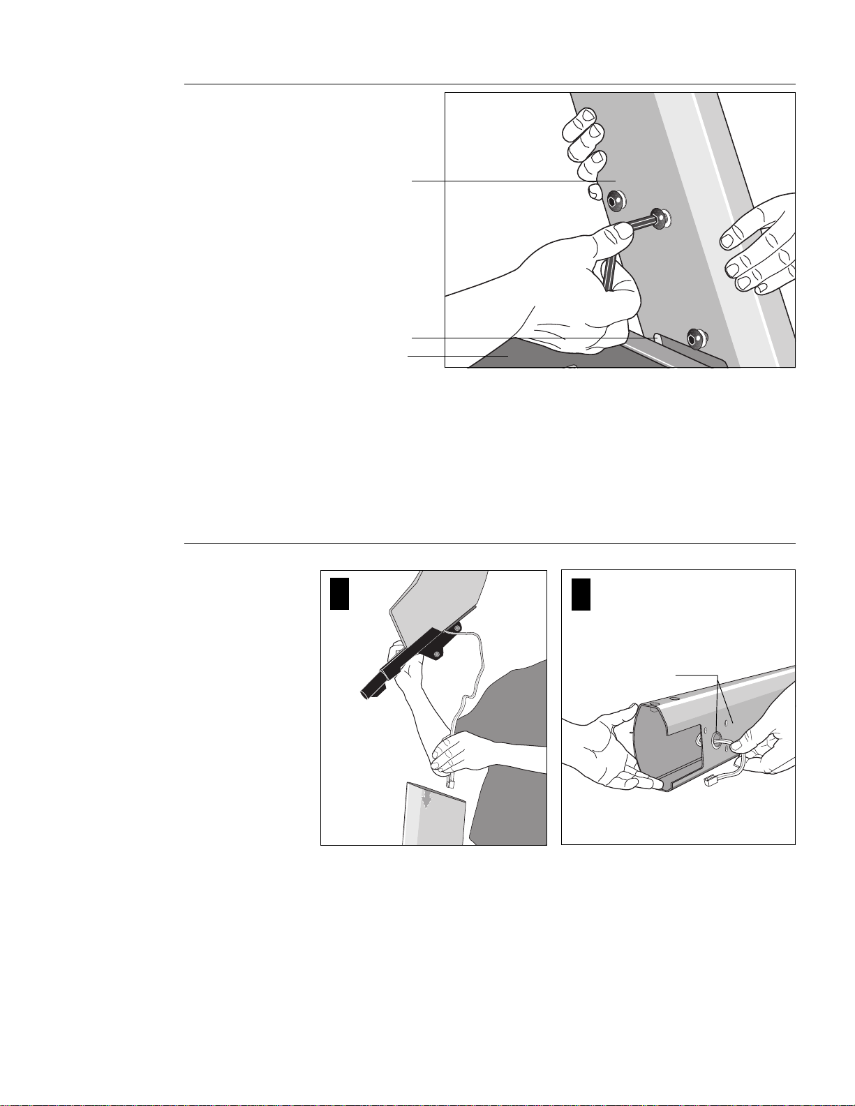
Diagram 3
Attach the left upright
support to the base.
Upright support
(left side)
Column support
Base assembly
Diagram 4
6. Attach the
the
left
support into the base assembly and align all 5 mounting holes (3 on the side, 2
in the front). Insert 5 screws (A) and washers (B). Thread the screws into the
unit, but leave them loose for final adjustments. Do not securely tighten the
screws until after the display console and handrails have been installed.
Note: The left or r ight side of the treadmill can be deter mined when you stand
near the rear roller and face the motor.
left side
upright support. This is the one you want to install first. Place the upright
upright support to the base assembly. Diagram 3. Locate
Route the cable through the upright support.
1
2
Route the cable through the hole
and tape it to the side of the
upright support.
CAUTION: To avoid damage to the display
cable, read and follow these steps carefully. Damage to the cable due to improper
assembly is not covered by the Precor
limited warranty.
page 12
7. Route the display cable. Diagram 4. Have an assistant hold the other support
upright. See “Note:” below. Position the display console above the upright
support and route the cable through it. Pull the cable through the hole in the
upright support. Lay the display console and upright support on the floor.
Note: Tying one end of a string to the end of the cable and the other end to a
washer may help in routing the cable. You can drop the washer through the
upright support and pull the cable through. Refer to Diagram 4, #2.
8. Secure the display console to the upright support. Diagram 5. Attach the
console to the right side support before placing the assembly onto the treadmill.
To do this, take the following steps:
Page 13
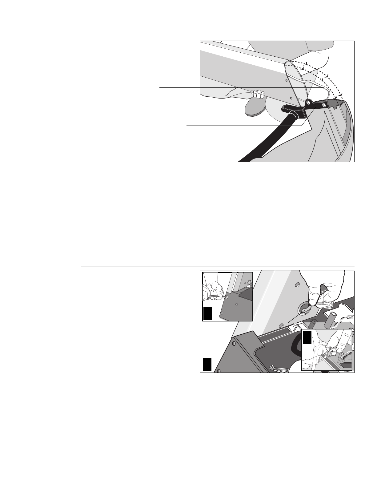
Diagram 5
Attach the display
console.
Upright support
Cable
Right side support
Display console
(bottom side)
a. Make sure that the cable is routed through the hole in the upright support.
b. Place a protective base (cardboard or plastic sheeting from the shipping
container) on the floor. Position the display console (display-side down) onto it.
c. Remove 2 screws (A) and washers (B) from the hardware kit.
d. Align the upright suppor t mounts with the display console’s. Insert 2 screws and
washers. Tighten the screws securely with the hex key provided.
9. Attach the display console assembly to the base. Diagram 6. Take the
following steps to install the display console assembly onto the treadmill.
a. Position the display console and right upright support over the column support
mount located on the base.
Diagram 6
CAUTION: Do not crimp or pinch the cable!
Crimped or pinched cables are not covered
by the Precor limited warranty.
Connect the cable
and attach the right
side support to the
base.
2
Route cable
through hole.
3
1
b. Carefully lower the upright support and align the mounting holes. See Diagram 6
#2. Check that the display console is seated proper ly on the left upright support.
Insert 5 screws (A) with washers (B). Thread the screws into the unit, but leave
them loose for final adjustments. Do not securely tighten the screws until after the
display console and handrails have been installed.
c. Plug the connector into its receptacle on the lower board. A definite “click” is
heard when the cable is properly attached. See Diagram 6 #3. If you do not hear
and feel the connector “snap” into place, reinsert it.
page 13
Page 14
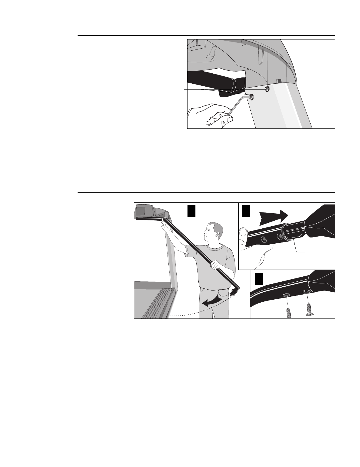
Diagram 7
Attach the
console to the left
upright support.
Buttonhead screws
10. Secure the display console to the left upright support. Diagram 7. Align the
mounting holes on the console to those on the left upright support. Insert 2
screws (A) and washers (B). Do not securely tighten the screws until after the
handrails have been attached.
Important: With the handrails attached, the width of the treadmill is 36.75”
(93 cm). It will not fit through a standard 36” doorway.
Diagram 8
Handrail alignment and installation.
1
2
Console
extension
3
11. Attach the handrails. Diagrams 8 and 9. For ease of assembly, place the side
rails or rear feet on blocks. Obtain assistance to lift the treadmill. Do not place
blocks beneath the running bed.
To attach the handrails, perform the following steps on
a. Alignment pins on the top of the handrails necessitate sliding the handrails into
the console assembly at an approximate 45o angle. Position the handrail as
shown in Diagram 8 and slide it onto the console extension. When the alignment
pins are fully engaged, carefully lower the handrail toward the base. Place as
washer (D) on each of 2 screws (C). Insert the screws and finger-tighten.
one side at a time
:
page 14
Page 15
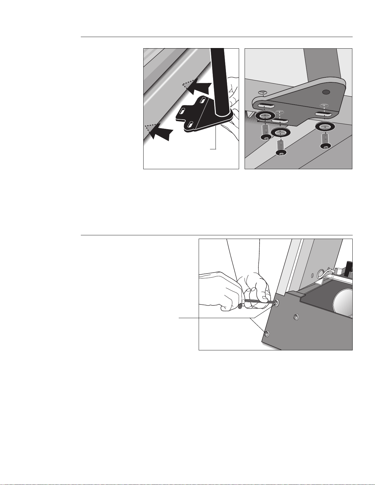
Diagram 9
Secure the handrail to the base.
Handrail bracket
b. Align the handrail bracket with the 3 base mounts and insert 3 screws (A) and
washers (B). See Diagram 9. Tighten the screws securely.
c. Retur n to the upper handrail screws and securely tighten each one.
d. Perform steps a. through c. on the opposite side.
e. Obtain assistance and remove the blocks from beneath the base.
Diagram 10
Tighten front plate
screws first. Then
securely tighten
all fasteners.
Tighten these
screws first on
both sides of the
front plate.
12. Tighten all mounting screws with the hex keys provided. Diagram 10. Star t at
the front of the treadmill with the 4 screws that attach the upright supports to the
front plate. Tightening these screws first helps pull the rest of the treadmill’s par ts
into alignment. Then, proceed with securely tightening the upright supports and
console assembly screws.
page 15
Page 16
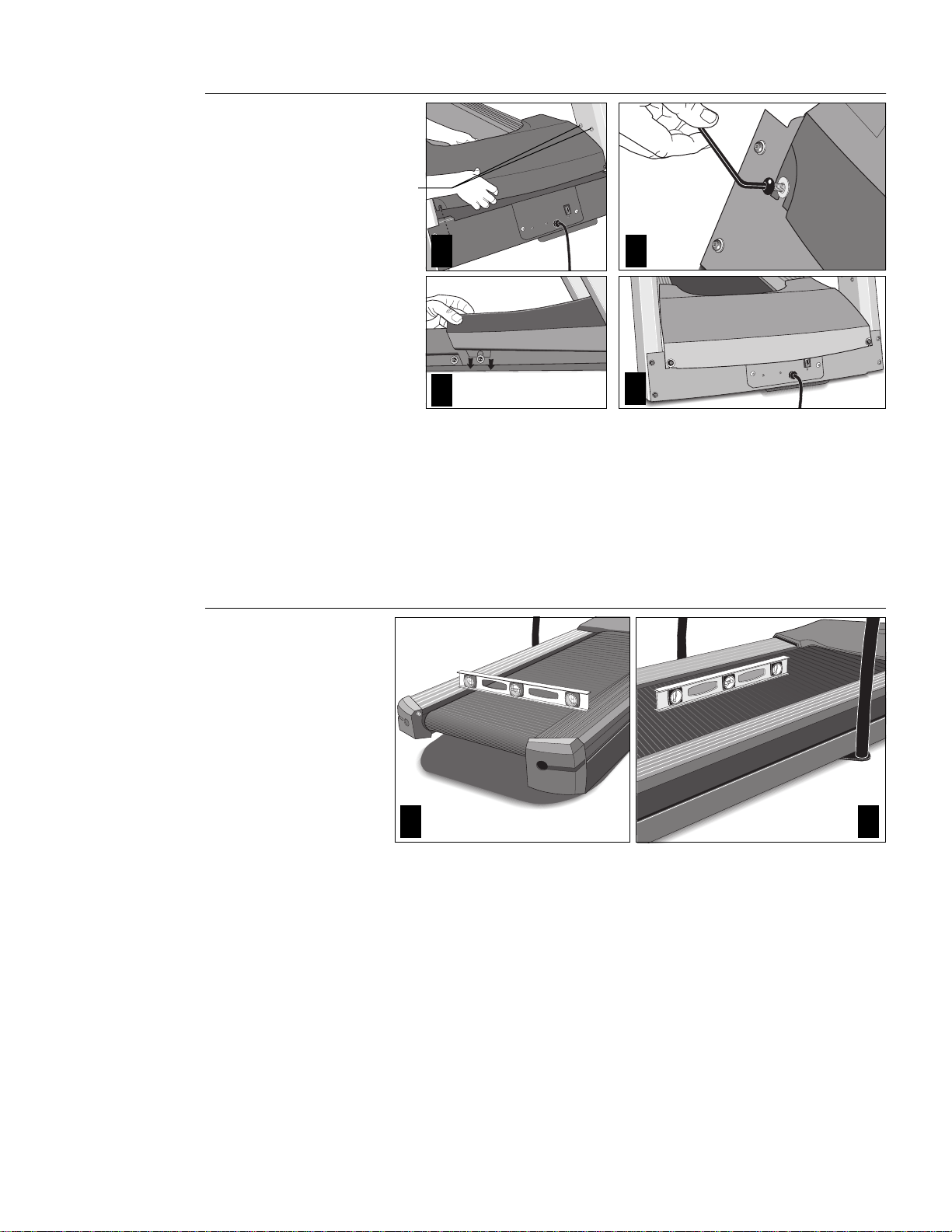
Diagram 11
Secure the
hood.
Slide the
hood under
the 2 screws
found on the
inboard side
of both
upright
supports.
1
3
CAUTION: Do not overtighten the screws
or you may inadvertently cause stress
cracks in the plastic hood.
Diagram 12
2
13. Attach the hood. Diagram 11. Place the hood over the motor and slide it
the upper 4 screws (see Diagram 11 #1) and
on each side) of both upright supports.
As you lower the hood, slide the hood under the washers and onto the screws (2 in
the front, 1 on either side of the treadmill). See Diagram 11, #2 and #3. Retighten the
screws that you loosened in step 4.
tween the base assembly and the washers. The washers must be on the
outside of the hood.
Level
the
unit.
Tighten the screws securely using the hex key provided.
4
over
the 2 lower screws (1 found
Be sure that the hood is sandwiched be-
under
21
page 16
14. The M9.55 has adjustable rear feet. Check to make sure that the running surface
is level (use a bubble level as shown in Diagram 12). If the treadmill is placed on
a slightly, uneven surface, adjusting the rear feet can help, but will not compensate for extremely uneven surfaces.
Page 17

Diagram 13
Adjust
the rear
foot.
CAUTION: Ask for assistance to lift the
rear of the unit slightly off the floor. Lift
the unit by its side rails. Trying to lift the
unit and adjust the rear foot without
assistance may cause injury to yourself
or damage to the unit. Do not try to lift the
unit using the running belt.
CAUTION: Never remove or bypass the
3-prong plug on the unit’ s po wer cor d with
an adapter. Do not use a non-grounded
outlet. Do not plug the treadmill into a
power transformer in an attempt to adjust
the voltage requirements.
Important: If you need to make adjustments, adjust one rear foot at a time. Do
not use the rear foot to raise or lower the unit more than 1/4” in height. Check
the level of the unit after each adjustment.
15. To adjust a rear foot, locate the nut that secures the rear foot to the deck. See
Diagram 13. Loosen the nut with a crescent wrench or appropriate open-end
wrench until you can easily turn the foot. See inset in Diagram 13.
16. To raise the rear deck, turn the foot clockwise and make the proper height
adjustment. Then, retighten (counterclockwise) the nut securely using the
wrench.
Turning the Unit ON and OFF
Use the ON/OFF (I/O) power switch to turn the unit ON and OFF. This switch is
located on the front of the unit, near the power cord.
The treadmill requires a dedicated circuit. Plug the power cord into a dedicated
20 amp, grounded, power source. Make sure that no other product or machine
uses the same circuit as the treadmill.
To complete the installation of the treadmill, continue to
Running Belt
on the next page
.
Checking the Alignment of the
page 17
Page 18

Checking the Alignment of the Running Belt
The belt is aligned at the factory before shipment. However, during shipment or by
using the treadmill on an uneven surface, the belt might move off center. Proper belt
alignment is important because it allows the belt to remain centered and assures
smooth operation.
Follow these steps to check the alignment:
CAUTION: Do not walk on the running belt
during this procedure.
CAUTION: If you hear any chafing or
the running belt appears to be getting
damaged, stop the running belt immediately by pressing the STOP key. Contact
Customer Support.
1. The treadmill has adjustable rear feet. Check to make sure that the running
surface is level (refer to steps 14 - 16 on the previous pages). If the treadmill is
placed on a slightly uneven surface, adjusting the rear feet can help, but will not
compensate for extremely uneven surfaces.
2. Locate the ON/OFF (I/O) switch at the front of the treadmill and turn the unit ON.
3. Stand beside the treadmill and press Quick Start.
4. If necessary, enter the password: Incline ▼, Speed ▼, Speed ▲.
The running belt starts automatically after the message, “
appears.
5. Continue standing next to the treadmill and hold down the Speed ▲ key until the
display shows a speed of 3 miles per hour (5 kph).
6. Walk around to the rear of the unit and observe the belt for a few minutes as it
moves.
If the running belt,... Then,...
tracks centered on the running surface the belt is functioning correctly
(evenly distributed between the side rails) and no adjustment is necessary.
runs or drifts off center you need to adjust the belt; see
Aligning the Running Belt,
Important: If you notice that the belt needs alignment, make the adjustments at
once. Failure to do so might cause the belt to tear or fray which is not covered by
the Precor limited warranty.
Belt Starting 3, 2, 1,...
page 42.
”
7. To stop the running belt, press the red Stop button.
If the belt is functioning correctly, the M9.55 treadmill is ready to use.
page 18
Page 19

Using the M9.55 Treadmill
3
CAUTION: Do not allow children on or
near the treadmill at anytime. If anything
should get caught in the rollers, the
running belt does not stop immediately.
A special feature of the M9.55 is its interactive display which lets you select a user I.D.
(1 of 4) and enter workout specific information such as, weight, preferred course, and
age. Each person that uses the treadmill (up to four people) can have their own user I.D.
and personalize their workout session. Refer to
When you begin a course, the treadmill displays your workout statistics. O nce your
workout is complete, the cumulative totals (Time, Distance, and Calories) are stored
with your user I.D. By selecting the same user I.D., prior to your next workout, the
information about your weight, preferred course, age, and cumulative wor kout records
is retrieved and appears on the display. You have the option to
COURSE, and AGE fields, or press Enter to begin working out.
Your treadmill also contains a
tive display and start your workout immediately using the Manual course. When you
press Quick Start while the Precor banner is displayed, your workout statistics are not
saved to any particular user I.D. Refer to
learn more about this particular feature.
This section provides workout tips and information about:
• safety features • using the
• quick steps to working out • pause and exit features
• cooling down after a workout
Safety Features
The M9.55 treadmill is a powerful machine. Children should
near the treadmill. You should assemble and use the treadmill in a safe and secure
location. Other safety aspects to consider include:
• Always attach the security clip to your clothing prior to working out.
• To help prevent unauthorized use, the M9.55 provides password protection. The
password is enabled at the factory. Refer to
• Prior to the start of a course, the display will return to the Precor banner if more
than 2-minutes elapse without a key press occurring. This feature is helpful if you
get called away just prior to starting your workout. However, do not assume that
this feature makes the treadmill secure from unauthorized use.
Quick Start
User I.D.
feature which lets you bypass the interac-
Using the Quick Start Feature
on page 28.
change
Quick Start
not
be allowed on or
Entering a Password
the WEIGHT,
on page 23, to
feature
below.
CAUTION: Before beginning any fitness
program, have your physician give you a
complete physical examination.
Using the Security Clip
A security clip is attached by its cord to the red Stop button above the center
handrail. Always attach the security clip to your clothing before each workout. A tug
on the cord trips the security switch and slows the running belt to a stop. If the
security switch trips while you are working out, the treadmill retains your workout
statistics and enters Pause mode. To resume your workout, reattach the security clip
to your clothing, and press the Speed ▲ key until you reach the desired speed.
Note: A Velcro® patch is located on the right side of the console by the handrail. Use
it to store the clip while the treadmill is not being used.
Entering a Passwor d
The M9.55 is equipped with password protection to help prevent unauthorized use. The
password involves entering the following key sequence: Incline ▼, Speed ▼, and Speed
▲ at the password prompt. An asterisk appears on the display with each correct entry. If
the correct password is not entered within 2 minutes, access to the course is denied and
the running belt will not move. The Precor banner reappears on the display.
page 19
Page 20

CAUTION: Before beginning any fitness
program, you should obtain a complete
physical examination from your personal
physician.
Work out Tips
The steps to working out on the treadmill are listed on the next page. A short description appears in the left margin with the more thorough explanation following on the
right. Tips to consider during your workout are shown below:
• Check that the unit is turned ON. The I/0 switch is located on the front panel.
• Review the
Safety Instructions
• Select a user I.D. (or user name) so that you can personalize your workout. Refer
to
Creating a User Name
• At the Precor banner, pressing Quick Start bypasses further selections and
starts the running belt. Default values may apply (see
Smart Rate® is not active.
• Entry of a password may be required before accessing a course.
Safety Features
written on the inside cover.
on the previous page and follow the
on page 31.
Quick Start
Important
on page 31).
Diagram 14
Smart Rate
®
M9.55 display
Heart rate display
User I.D. (or user name) displa y
Display and data entry fields
Informational displays vary depending on which
item in the column below it is highlighted.
Change keys
Press CHANGE to retrieve new data and
change specific information.
Number keys
The first four keys can be used at the Precor
banner to access a user I.D .
Keypad keys
The keys on the keypad let you:
• control your workout session,
• answer prompts prior to starting a course,
• prematurely end a course, and
• adjust cer tain aspects of your workout.
Refer to Keys on the Display Console on
page 29.
USER1
Field 1 Field 2 Field 3 Field 4
Smart Rate® — When you wear the POLAR® chest strap, a blinking segment
approximates your heart rate and shows you which zone your heart rate is in:
weight loss or cardiovascular.
Heart Rate display — helps you monitor your heart rate and, in the Heart Rate
course, keeps you within your target zone. You must wear the POLAR® chest strap
and enter your weight and age before your heart rate can appear on the display.
page 20
User I.D. or name — One of 4 user I.D.’s or names can appear on the display. Choosing
a user I.D. enables the treadmill to identify you and track your cumulative workout
statistics. If other people use the treadmill, each person (up to 4 people) can select their
own user I.D. and personalize their workout session. To learn how to change a user I.D. to
a name (5 letter maximum), refer to
Display and data entry fields — When you select a User I.D., the display becomes
and interactive tool. You can
WEIGHT, COURSE, or AGE. And, you can view the records (TIME, DISTANCE,
COURSE, and CALORIES) that were stored for this user I.D. during the last workout.
When you elect to
new information. For a more detailed desription of what can appear in this interactive
display, refer to
change
Changing the User Display Fields
any data field (such as, WEIGHT), the display retrieves
Creating a User Name
change
information for your upcoming workout such as,
on page 33.
on page 26.
Page 21

Quick Steps to Working Out
1
Put on the POLAR® chest strap.
2
Turn ON the treadmill.
3
Straddle the running belt.
4
Attach the security clip to clothing.
5
Select a User I.D.
Important: Before working out, review
the information regarding the different
M9.55 courses and their operation. Brief
course descriptions start on page 3 5.
6
Accept or change the WEIGHT,
COURSE, or AGE information.
Important: If you choose one of the
“goal” based courses, you will be
prompted for more information before
the password prompt appears.
7
Enter a password.
CAUTION: Hold onto the handrail(s)
if you pressed the Quick Start key.
After password entry (if it’s enabled),
the running belt begins moving at 1
mph (1.5 kph). Default values apply.
Refer to Quick Start on page 31.
8
Begin working out. Press Speed ▲.
Hold onto the handrail with one hand.
Step onto the belt while it is at 1 mph
(1.5 km).
(Pause)
1. For your heart rate to appear on the display, you need to wear a POLAR® chest
strap. Refer to Chapter 7 for more information.
2. Locate the ON/OFF (I/0) switch at the front of the treadmill and turn ON the
treadmill. The Precor banner appears on the display console.
3. Straddle the running belt with your feet firmly planted on the right and left staging
platforms. (Stand close enough to the display console so that you can extend
your arms and touch the keys.)
4. Attach the security clip to your clothing near your waistline.
Note: To access the Manual program, press Quick Start while the Precor banner
is being displayed. For more information, refer to
Using the Quick Start Feature
.
5. While the Precor banner is displayed, press Enter or use the number keys (1 to 4) to
select a particular user I.D. If you press Enter, the user I.D. associated with the
person who last used the treadmill appears. Review the information on the display.
Note: When the user I.D. name or number appears , the cumulative totals for workout
time (TIME), distance (DISTANCE), last course used (COURSE), and total caloric
burn (CALORIES) appear in the lower display. The data that appears in the WEIGHT,
COURSE, and AGE fields can be changed. For more information, refer to
the User Display Fields
on page 26.
Changing
6. Your weight, course, and age need to be entered to activate all the features
available on your treadmill. If you wish to change the WEIGHT, COURSE
number, or AGE, while your user I.D. (or name) is being displayed in the upper
window, press the Change key to highlight the appropriate field. (Refer to the
“Note” above.) To
change
the blinking field information, use the number or ▼▲
keys. To begin working out, press Enter.
The first time you use the treadmill, be sure to enter your WEIGHT and AGE so
that the information is stored with your user I.D. If the information is stored
properly, you can use the heart rate and Smart Rate® features.
Note: You can press Quick Start to accept your entries. After entering the
password, hold onto the handrail because the belt starts moving after the short
warning message, “
Belt Starting 3, 2, 1,...
” appears on the display.
7. The M9.55 is equipped with password protection to help prevent unauthorized
use. The password involves entering the following key sequence: Incline ▼,
Speed ▼, and Speed ▲. An asterisk appears on the display with each correct entry.
If a correct password is not entered within 2 minutes, the Precor banner reappears and access to the course is denied.
Note: When returning to a course from Pause mode, you are also prompted for
the password.
If you feel that your work out and home environment makes the password
unnecessary, you have the ability to eliminate password protection. Refer to
Securing the Treadmill with a Password
8. Hold onto the handrail with one hand while you press the Speed
on page 33.
▲▲
▲ key with the
▲▲
other hand. Step onto the running belt while the speed is at or 1 mph (1.5 kph).
Once you are comfortable with the walking or running speed, you can remove
your hands from the handrail.
Note: To pause during your workout session before finishing the selected program,
press the red Stop button. The displays on the console freeze. See
Down, Work out Summary and Exit Features on page 23
for more information.
Pause, Cool
page 21
Page 22

Quick Steps to Working Out
9
Continue your workout.
10
End your workout.
Important: Always incorporate a cool-
down period into your workout. If the
course you prefer doesn’t use the
automatic 5-minute cool down, press
the red Stop button to end the course
and then use the Manual course to
cool down.
11
Review your workout statistics
12
Remove the Security clip.
13
Turn OFF the treadmill.
9. Use the Incline ▼▲ and Speed ▲▼ keys to change the incline and speed during
your workout. Hold onto the handrail with one hand while you touch the keys with
the other. Note that the keys are very sensitive, you barely need to press the key
for a change to occur. Note that cer tain courses have preprogrammed speed and
incline changes. Refer to M9.55 Courses on page 35.
10. You can end your workout in one of two ways:
• pressing the red Stop button, or
• entering the automatic 5-minute cool down period that is appended to
several of the courses: Miracle Mile, Yellow Brick Road, Urban Park, 5K Run,
10K Run, Weight Loss, Time Goal, Distance Goal, or Calories Goal.
Note: Use ▼ or ▲ keys to decrease or increase the Speed and Incline during
your cool-down period.
Once you complete the automatic cool-down period, the running belt comes to a
complete stop and a Workout Summary banner appears. Workout statistics
TIME, DISTANCE, and CALORIES are added to your cumulative User I.D. totals
and all other statistics are reset to zero. (Note that the TIME display shows the
accumulated workout time including warm-up and cool down periods.)
Note: To access the Workout Summary from a course, that doesn’t incorporate
the automatic 5-minute cool down, press Stop and then, Reset.
11. You are given 2 minutes to review your workout statistics before the display
automatically resets to the Precor banner. You can also press Reset during that
time, to return to the Precor banner.
12. When the running belt comes to a complete stop, straddle the running belt,
remove the security clip from your clothing, and step off the treadmill.
13. Turn OFF the treadmill to help prevent unauthorized use.
Cooling Down After Y our Workout
Cooling down after your workout helps reduce muscle stiffness and soreness by
transporting excess lactic acid out of the working muscles. It also helps your heart
rate return to its normal (non-exercising) state.
The M9.55 treadmill automatically appends a cool-down period to several of the
M9.55 courses. (See “Important” below.) A message appears and notifies you that
you have reached the end of the course and the cool-down period is about to begin.
The running belt slows by about 20% and the incline returns to 0%. The Manual
course profile appears in the display. You can change the speed and incline by
pressing the respective ▼ or ▲ keys.
During the 5-minute cool down, the displays on the console continue to appear. The
TIME display shows the time remaining in the cool down period.
To prematurely end the 5-minute cool-down period, press the red Stop button and
then Reset. Your workout statistics are added to the cumulative totals while the
running belt slows to a gradual stop. The Workout Summary display appears so you
can review your cumulative totals.
Important: The automatic 5-minute cool down does not occur when you are using
Manual, Track, Interval, Random, Heart Rate, or Custom courses. In any other
course, if you exit the course prior to its completion, then the automatic 5-minute cool
down program is not implemented.
page 22
Page 23

Using the Quick Start Feature
The words “Quick Start” imply that you can start your workout immediately. Once you
attach the security clip to your clothing, pressing Quick Start, while your user I.D. is
displayed, causes the running belt to start automatically after the warning message
“Belt Starting 3, 2, 1,...” appears on the display.
Since the treadmill’s software stores all workout information with your user I.D., the
weight, course number, age, duration/distance of workout, and course time are
reactivated and restored. The last course you used appears as the course profile on
the display.
If you press Quick Start at the Precor banner, you immediately enter the Manual
course. The course profile appears as a flat line. Accumulated workout statistics are
not stored with any particular user I.D. When you end your workout by pressing the
red Stop button and then Reset the workout statistics are not saved or added to any
cumulative totals.
Pause, Cool Down, W orkout Summary, and Exit Features
Pausing, cooling down, and exiting are integral parts of your workout and can be
accessed any time during a course. The treadmill goes through several prerequisites
before actually exiting a course.
Pause mode — can be accessed while in a course or during cool down. Note that
the Pause mode has a 2-minute time limit. If no key presses occur during that time,
the workout statistics are added to the cumulative totals and the display returns to the
Precor banner.
Cool down mode — automatically appends a 5-minute cool-down period to the end
of your workout when you complete one of the following courses: Miracle Mile, Yellow
Brick Road, Urban Park, 5K Run, 10K Run, Weight Loss, Time Goal, Distance Goal,
or Calories Goal. If you exit the course prior to its completion, then the automatic
5-minute, cool-down program is not implemented.
Workout Summary display — provides a 2-minute time frame in which you can
review your workout statistics before the display automatically resets to the Precor
banner. The Workout Summary display can be accessed from the Pause or Cool
down modes, or by prematurely exiting a course. When you access the Workout
Summary display, workout statistics except TIME, DISTANCE and CALORIES reset
to zero. (Note that the TIME and CALORIES displays show the accumulated workout
time and expended calories including warm-up and cool down periods.)
page 23
Page 24

The following information shows what happens when you press certain keys while in
the various modes.
During a course,
you press This is what happens...,
CAUTION: Always hold onto the handrail
with one hand when pressing the display
keys with the other.
Stop Enter Pause mode. The running belt slows to a gradual
stop. Note that you may also press the Speed ▼ key until
zero appears on the display. Once the running belt stops,
TIME stops accruing. The display features remain, so you
can review your workout statistics. The Pause mode lasts
for 2 minutes (120 seconds).
While in Pause mode,
you press This is what happens...,
Speed ▲ Exits Pause mode and starts the running belt moving again
so that you can resume where you left off.
Reset Displays the W ork out Summary banner so that you can view
your workout statistics.
In Cool down,
you press This is what happens...,
Stop Enters Cool down - Pause mode. The running belt slows to
a gradual stop. TIME stops incrementing. The display
features remain, so you can review your workout statistics.
Note that the Pause mode lasts for 2 minutes.
Speed ▲ Starts the running belt moving again and retur ns to cool
down mode so that you can resume where you left off. TIME
continues to count down.
Reset Displays the Workout Summary banner.
At the Workout
Summary banner,
you press This is what happens,...
Reset Stores your cumulative workout records associated with the
user I.D. and the display returns to the Precor banner.
page 24
Page 25

The M9.55 Display
4
Diagram 15
The display console lets you control your M9.55 treadmill. The directions on the
console and the prompts on the display guide you through your workout session.
Before using the treadmill, we recommend that you familiarize yourself with it so that
you can use it safely and effectively. This section covers the following information:
• an explanation about the user I.D. display fields
• instructions for deleting workout statistics associated with a user I.D.
• an overview of the features appearing on the display
Features on the Display Console
As you work out, indicator lights show you which feature is being displayed. When
you enter a course, the display presents Time, Distance, Speed, and Calories. Y ou
can change what features appear on the display by pressing the Change keys.
The M9.55 can also store information about four separate users and recall statistics
and information from previous workouts. A separate file that stores data for each of
the four users corresponds to a specific user I.D. or name. Previous workout information about your weight, course number last used, age, and other workout statistics
can be accessed through your user I.D.
M9.55 Display Console
Smart Rate® bar graph
If a heart rate is detected, it is
displayed in this window.
Banner, user I.D., and course
profile display (LED matrix)
During course selection, the course #
appears here. Workout statistics and other
informational displays appear during a
workout or while in programming mode.
Change keys let you choose what information
to display. Press Change to retrieve new data
and change specific information.
Number keys can be used to answer prompts
and select incline and speed levels in a
course. The first 4 keys can be used at the
Precor banner to access a user I.D.
Touch-sensitive keys let you:
• control your workout session,
• answer prompts prior to starting a course,
• prematurely end a course, and
• adjust cer tain aspects of your workout.
As you exercise the display console provides motivation by presenting constant feedback
about your progress. A brief explanation of each feature on the display console appears
in Diagram 15. The next few pages provide a more thorough explanation.
Note: If an error message appears, call a Precor qualified service technician or
service center. For the service center nearest you call, 1-888-665-4404.
page 25
Page 26

Changing the User Display Fields
When a user I.D. is displayed, you have the option to change the WEIGHT, COURSE,
and AGE displays by pressing a Change key and highlighting the information.
If you press the Change key to highlight WEIGHT, the information that appears on
the display changes accordingly. The information in the WEIGHT field (Field 2) blinks,
indicating that the treadmill is awaiting your input.
Diagram 16
Center display indicates which
user I.D. or name is associated
with the field displays.
Press Change to highlight WEIGHT,
COURSE, or AGE fields.
Press one of the first 4 number keys
while at the Precor banner to select a specific
user I.D. To delete workout statistics associated with that user I.D. and reset the factory
defaults, hold the number key for more than
14 seconds.
M9.55 Setup display.
Upper
Display
Field 1 Field 2 Field 3 Field 4
The same is true when you press the Change key to highlight the COURSE or AGE
fields. Diagram 16 illustrates the different fields that exist within the display. The
following information describes what appears in the fields.
page 26
USER#
Note: Use the number or ▼▲ keys to change the blinking (highlighted) information.
When the User’s # or Name appears in the Upper Display:
Field 1 indicates the cumulative time spent on the treadmill. If the time spent on the
treadmill is less than one hour, the time is displayed as 0:MM (where MM equals
minutes). Less than 100 hours and time appears in hours and minutes (HH:MM). if
the cumulative time is greater than 100 hours, then time appears as hours only. The
number rolls over to zero when cumulative time becomes greater than 99999 hours.
Field 2 provides the cumulative distance in miles or kilometers depending on what
units of measure you choose. Refer to
Field 3 shows the number of the last course used.
Field 4 displays the cumulative calories.
Programming the M9.55 Treadmill
on page 32.
Page 27

WEIGHT
When the User’s # or Name appears in the Upper Display and you press the
Change key found directly below the WEIGHT indicator, the information in the
WEIGHT field begins to blink indicating that the treadmill is awaiting input. You can
change the number (from 1 to 999) using the ▲▼ keys or number keys. Once you
start working out, the WEIGHT indicator is disabled.
Field 1 indicates the cumulative time spent on the treadmill.
Field 2 shows the weight that you last entered.
Field 3 provides the number of the last course used.
Field 4 displays the cumulative calories.
COURSE
AGE
When the User’s # or Name appears in the Upper Display and you press the Change
key found directly below the COURSE indicator, the COURSE # begins to blink and
the course profile associated with the course numberappears in the upper display.
Once the COURSE field (Field 3) is blinking, you can change the number (from 1 to
18) using the ▲▼ keys or number keys. Once you start working out the COURSE
indicator is disabled.
Field 1 indicates your best (or record) time that it took to run or walk the course. For a
fixed distance course, TIME displays your record time (the least amount of time it took to
run or walk the course). Otherwise the TIME display is blank or shows the time it took to
complete the course. Course times are displayed in hours and minutes (HH:MM).
Field 2 shows the distance in miles (or kilometers) that consists of your best (or
record) time for the course. Refer to
Field 3 provides the number of the last course used.
Field 4 displays the highest number of calories burned while using the course. Note
that the field is blank if the Calories Goal course number appears in Field 3.
When the User’s # or Name appears in the Upper Display and you press the
Change key found directly below the AGE indicator, the information in the AGE field
begins to blink indicating that the treadmill is awaiting input. The age is associated
with the user I.D. and can b e changed (from 1 to 99) using the ▲▼ keys or number
keys. Once you start working out the AGE indicator is disabled.
Field 1 indicates the cumulative time spent on the treadmill.
Programming the M9.55 Treadmill
on page 32.
Field 2 provides the cumulative distance in miles or kilometers depending on what
units of measure you choose. Refer to
Field 3 provides the number of the last course used.
Field 4 displays the number associated with your age.
Programming the M9.55 Treadmill
.
Deleting W orkout Statistics
To clear the workout statistics associated with a particular user I.D., you must take
the following steps.
At the Precor banner,
1. Select the user I.D. using a number key (1 - 4).
2. Press and hold the number key for about 14 seconds until you see the word
“CLEARED” appear on the display. Workout statistics are zeroed and default
values for course (#1, Manual), weight (150 lbs or 68 kg), and age (0) are restored.
The Goal and Interval course parameters are reset to factory standards.
page 27
Page 28

Smart Rate® Display
You must enter your “AGE” after selecting a user I.D., and wear a POLAR® chest strap,
while in a course program, before the blinking segment in the bar graph can show
which zone your heart rate is in: Weight Loss or Cardiovascular.
• Weight Loss Zone: Maintaining your heart rate between 55% and 70% of your
maximum aerobic heart rate, helps burn enough calories that, when continued on
a regular basis for 30 minutes or more, provides the greatest fat-burning results.
• Cardiovascular Zone: Maintaining your heart rate between 70% and 85% of your
maximum aerobic heart rate, helps you (when continued on a regular basis for 30
minutes or more) improve your overall cardiovascular/cardiorespiratory fitness level.
Important: During a course, your heart rate must be above 40 beats per minute
before the segment begins to blink. Note that pressing Quick Start may disable
the Smart Rate
®
display feature. See
Quick Start
on page 31.
Heart Rate Display
The heart rate display lets you monitor your heart rate. When a heart beat is detected,
the number appears in the small upper right display (refer to Diagram 15) and blinks in
time with your pulse. If you are not wearing a POLAR® chest strap, your heart rate will
not be detected and no pulse rate appears.
Upper Display
The Precor banner, user I.D. (or name) and course profiles appear in the large upper
display (dot matrix). Always start a workout at the Precor banner. During workouts,
the course profile appears in the upper display and corresponds to the course that
you selected. As you proceed through your workout, your position is indicated by a
blinking column.
User I.D: One of four user I.D.’s can appear on the display. Choosing a user I.D.
enables the treadmill to identify you and track your cumulative workout statistics. It
stores information about your weight, preferred course, age, cumulative workout
statistics, and track record. Refer to
Changing the User Display Fields
on page 26.
Lower Display
Prompts appear in this alphanumeric display prior to your workout. You address each
prompt using the number or keypad keys. Once you begin a workout, lights appear in
the columns below the window indicating which information is being displayed. You
can highlight a particular feature by pressing the appropriate Change key.
The following describes the information that can appear in the display.
TIME: During your workout, a time (0:00) display appears when you begin working
out. Time appears in minutes and seconds. However, should you exceed 60 minutes
(during a single workout), the Time display converts to hours and minutes. Usually,
the Time display shows how long you’ve been working out. However, in warm-up and
cool-down periods, the Time display indicates the minutes remaining. This also
occurs in a course that has a specified duration.
DISTANCE: The distance that you have travelled appears (00.00) once you begin a
workout. Distance can appear in miles or kilometers. If you wish to change the display,
follow the instructions found in
SPEED: Displays the running belt’s speed. The ▼ and ▲ k e ys let y ou decrease or increase
the treadmill’s speed. The running belt speed ranges from 0.5 to 12 mph
(1 to 20 kph). You can also use the number keys to designate the speed, once the running
belt is moving. Refer to Number Keys and Speed Control ▼▲ on pages 30 and 31.
Programming the M9.55 Treadmill
on page 32.
page 28
Note: You can check the speed (when it is not the chosen display) any time during your
workout by lightly pressing either Speed ▼ or ▲ key (for less than 2 seconds). Pressing
the Speed ▼ or ▲ key for more than 2 seconds causes the treadmill’s speed to change.
Page 29

CALORIES: Provides the cumulative number of calories currently being burned.
SEGMENT TIME: Indicates the amount of time, in minutes and seconds (MM:SS),
that remain in the highlighted column (or segment) before the next column begins
blinking.
INCLINE: Displays the percent of incline during your workout. The Incline ▲ and ▼
keys affect the treadmill’s lift and let you set an incline between 0% and 12%. The
values displayed can change in ½% increments. You can also use the number keys to
designate the incline, once the course has begun. Refer to Number Keys and
Incline ▲▼ on page 30.
Note: You can check the incline (when it is not the chosen display) any time during your
workout by lightly pressing either Incline ▲ and ▼ key for less than 2 seconds. Pressing
the Incline ▲ and ▼ key for more than 2 seconds causes the treadmill’s incline to
change.
METS: Displays the metabolic units associated with your workout.
CALORIES PER MINUTE: Indicates the approximate number of calories being
burned per minute.
PACE: Displays your target speed in minutes and seconds per mile (or kilometer).
Note: WEIGHT, COURSE and AGE display fields are discussed on page 27.
Keys on the Display Console
The Precor “touch-sensitive” treadmills have an easy-to-use keypad that is activated by
the slightest touch. You only need to apply gentle pressure to these ultra-sensitive keys.
Each key on the display console’s keypad provides specific functions. Number keys
(numbered 1 - 0) let you enter data in answer to the display prompts and change the
speed or incline during a workout. The standard keys, Change, Reset, Incline ▲▼,
Quick Start, Speed Control ▼▲, and Enter, let you enter data as well as control
your workout.
The following information explains the different uses of the keys from left to right. To
locate each key, look at the display console or refer to Diagram 17 on the next page.
page 29
Page 30

Diagram 17
Keypad keys.
Numeric keys: Indicate course #, time limit,
or goal entries. During a workout, use these
keys to select a target Speed or Incline.
Quick Start: When pressed at the Precor
banner, starts moving the running belt.
Smart Rate® is inactive and default values
apply.
R
E
S
E
1
T
2
3
4
5
I
N
C
L
I
N
E
6
8
7
D
E
E
P
S
0
9
L
O
R
T
N
O
C
R
E
T
N
E
Keypad Tips
• Accurate entries are required or features such as Smart Rate® may not work properly.
• Press Enter to select the information being displayed.
• Quick Start bypasses further selections and causes the running belt to start
moving. Default values may apply (see
Rate® display may not appear.
• A time-out occurs prior to starting a course if the treadmill detects no key
presses for 2 minutes. The display returns to the Precor banner.
• Press Reset to return to the Precor banner.
• The Stop button does not appear in Diagram 17, but its function is vital as
explained in this section.
Number Keys (1 - 0): During a workout, you can use the number keys to change the
treadmill’s speed or incline (in whole numbers or increments). The range of speed
includes 0.5 - 12 mph (1 - 20 kph).
QUICK START
on page 31). The Smart
Note: When you use the number keys to change the incline, you need to press the
Incline ▲ or ▼ key within 3 seconds to initiate the lift. The actual incline appears on
the display as the lift moves toward the target position. If you wish to halt the lift’s
movement, press either the Incline ▲ or ▼ key. The lift stops moving and the display
shows the current incline level. A similar situation occurs when you use the number
keys to change the speed, only it’s the running belt that is being affected.
At the Precor banner, you can also use the number keys to select a user I.D. Once
the user I.D. display appears, the number keys can be used to enter a weight, course
number, workout time, “goal” entry, and age. Note that you must press Enter to
process your selection.
CHANGE: During a workout, the Change key lets you choose which feature appears
on the display. In the user I.D. display, the Change keys let you “change” the
WEIGHT, COURSE, or AGE selections.
RESET: While in the user I.D. display or when the running belt is stopped, you can
cancel the program, clear the display, and return to the banner by pressing Reset.
INCLINE
▲▼▲▼
▲▼: During a workout, the Incline ▲▼ keys let you increase or decrease the
▲▼▲▼
running bed’s incline. The incline changes can range from 0% to 12% in 0.5% increments. The incline in many courses is preset, but can be overridden by the user. In the
Heart Rate and Weight Loss courses, the incline may change automatically to maintain
a designated target heart rate.
When you press the Incline ▲▼ keys, the number that appears on the display shows
the target incline (not the actual incline) because the display can change much faster
than the motor driven lift.
page 30
Another feature of the Incline ▲▼ keys lets you review the treadmill’s incline any time
during your workout. If INCLINE is not one of the chosen features being displayed, you
can view the actual incline by lightly touching either Incline ▲ or ▼ key. You can opt to
change the incline, if you hold the key down for more than 2 seconds.
Note: Lightly pressing an Incline ▼ or ▲ key, while INCLINE is being displayed,
causes the incline to change. The number keys can also be used to adjust the incline.
Please refer to
Number keys
above.
Page 31

STOP: When the red Stop button is pressed, the running belt slows to a gradual stop.
The treadmill remains in Pause mode. If the lift was moving when the Stop button
was pressed, the lift stops also and remains at its current incline level.
To resume a workout, the Speed ▲ key must be pressed. If no key press is detected
and the Pause time limit elapses, the display returns to the Precor banner. A default
time limit of 2 minutes exists.
Important: As a safety feature, a sharp tug on the security cord that is attached to
the Stop button will cause the running belt to stop. It is a requirement that a user
attach the security clip on his or her clothing while working out. Please refer to
the Security Clip
on page 19.
Using
SPEED CONTROL
▼▲▼▲
▼▲: The Speed ▲ key initiates the movement of the running belt
▼▲▼▲
at the beginning of a course and lets you designate the target speed. During a
workout, the Speed ▼▲ keys let you increase or decrease the running belt’s speed.
Speed changes can range from 0.5 to 12 mph (1 to 20 kph) in 0.1 increments. The
speed in the Interval course can be programmed by the user.
Note: When you press the Speed ▼▲ key, the number that appears on the display
shows the target speed and may differ slightly from the actual speed because the
display can change much faster than the running belt. Eventually, the two meet at the
target speed.
Another feature of the Speed ▼▲ keys lets you review the treadmill’s speed and
pace any time during your workout. If SPEED is not one of the chosen features being
displayed, you can view the speed of the running belt and your pace by lightly
touching the Speed ▼ or ▲ key. A 2-second display lets you review your speed and
pace. You can opt to change the speed, if you hold the key down for a few more
seconds.
Note: Lightly pressing an Speed Control ▼ or ▲ key, while SPEED is being dis-
played, causes the incline to change. The number keys can also be used to adjust
the incline. Please refer to
Number keys
on the previous page.
QUICK START: Quick Start lets you bypass the user I.D. selection and start your
workout immediately using the Manual course.
Default values apply.
QUICK START Default Values
Prompts Default Value
Course Manual
Time 30 minutes.
Weight 150 lbs. (68 kg.)
Age 0
An Age entry must occur to utilize the Smart Rate® display. If Quick
Start is pressed
after
an
Age
is entered, then the Smart Rate
display will appear when you wear the POLAR® chest strap. If no
Age
entry occurs, the Smart Rate® display lights up, but no blinking
sensor appears.
For more information about Quick Start, refer to page 23,
Feature
.
®
Using the Quick Start
page 31
Page 32

Programming the M9.55 Treadmill
5
Several aspects of the M9.55 treadmill can be programmed. This section provides
instructions on how to:
• select U.S. standard or Metr ic display
• enable or disable password protection
• create a user name
• view the odometer, hours of use, software version, and error log
Selecting a U.S. Standard or Metric Displa y
The M9.55 treadmill can display speed in either miles per hour (mph) or kilometers
per hour (kph) and distance in miles or kilometers. When the M9.55 is shipped from
the factory, it is set to display to U.S. Standard units of measure (mph and miles). You
can easily change this setting by taking the following steps:
1. Check that the treadmill is ON. If necessary, turn ON the treadmill using the
power switch located at the front of the hood.
2. At the Precor banner, use the red Stop button and number keys. Press the
following keys in sequence:
Red Stop button, 5, 6, 7, 1
The numbers 5, 6, 7, 1 appear on the display as you press the associated key.
Important: If the second key press (the number 5 key) is not pressed within
½ second after pressing the Stop button, the display returns to the Precor
banner. You will need to begin again.
3. The prompt, “Select Units” appears on the display. Then, the current unit of
measure appears. Any ▼ or ▲ key lets you alternate between the prompts.
4. Once your selection is displayed, three options exist. You can,
a. press Enter to accept the unit of measure being displayed and continue with
programming the treadmill. The changes have been retained in the
treadmill’s memory. The M9.55 treadmill will retain your selection even when
it is turned OFF and unplugged.
b. press Stop which keeps the current unit of measure unchanged and lets
you continue with programming the treadmill.
Note: The “current unit of measure” is not necessarily the one being
displayed. It refers to the unit of measure that was in existence prior to
entering the “Select Units” program.
c. press Reset which keeps the “current unit of measure” unchanged, ends the
programming mode, and returns to the Precor banner.
Important: If you choose to change the units of measure, then any existing
custom course records are deleted. Interval courses are also affected. Any rest
and work interval segments stored in memory are reset to 1 mph or 1.5 kph
(respective of which unit of measure you choose).
page 32
Page 33

Securing the Treadmill with a Pass w or d
Note: The password protection program is part of a 3-part sequence that starts with
Selecting a U.S. Standard or Metric Display.
If you chose step 4a. or 4b. in the previous programming step, the prompt, PASSWORD appears on the display. You can use the ▼▲ keys to cycle through the
available options:
Begin with the instructions on page 32.
WARNING: If you choose to change the
security of the treadmill, it is your responsibility to make sure that no unauthorized
personnel or children are allowed on or
near the treadmill.
Password Enabled — causes the password prompt to appear prior to working out
and when returning from Pause mode.
Password Disabled — lets you “turn off” the password requirement. Use this option
with caution.
Once your selection is displayed, three options exist. You can,
1. press Enter to accept the displayed information and continue with programming
the treadmill. The changes have been retained in the treadmill’s memory. The
M9.55 treadmill will retain your selection even when it is turned OFF and
unplugged.
2. press Stop which keeps the current security unchanged and lets you continue
with programming the treadmill.
3. press Reset which keeps the current security unchanged, ends the programming mode, and returns to the Precor banner.
Creating a User Name
Note: Replacing the User1, User2, User3, or User4 identification with a user name,
is part of a 3-par t program that star ts with
Display.
If you chose step 1 or 2 in the previous programming step, the prompt, USER NAMES
appears on the display. A user I.D. (i.e. USER1, USER2, USER3, USER4) appears in the
lower display. The
(If no user name has been created, then the user I.D. appears in both places.) The first
character (in the upper display) blinks indicating that the treadmill is awaiting your input.
Begin with the instructions on page 32.
name
associated with the user I.D. appears in the upper display.
Selecting a U.S. Standard or Metric
Important: A user name is limited to 5 characters. The name “FRANK” is acceptable,
but “MARCIA” is not.
To create or change the name, take the following steps:
1. Use the Speed ▲ key to advance through the alphabet. When the correct character appears, press Incline ▼ to move the cursor right to the next character field.
(The Incline ▲ key moves the cursor to the left.)
Note: Pressing Quick Start for about 5 seconds while the User I.D. is being
displayed, restores the default user name, User 1, User 2. etc.
2. Once your selection is displayed, two options exist. You can,
a. press Enter to accept the name being displayed and advances to the next
user I.D. The changes have been retained in the treadmill’s memor y. The
M9.55 treadmill will retain your selection even when it is turned OFF and
unplugged.
b. press Stop to keep the current User I.D unchanged and advance to the next
User I.D. Once all four user I.D.’s have been displayed, pressing Stop or
Reset exits the program mode and returns the Precor banner.
Note: The “current User I.D” is not necessarily the one being displayed. It
refers to the user I.D’s that were in existence prior to entering the program
mode.
page 33
Page 34

Viewing the Odometer , Hours of Use, Software Version and Error Log
Start at the Precor banner and press the Stop button. Then, within ½ second, initiate
the following key sequence.
Speed ▲, Speed ▼
Note: You can use the number keys (6, 5) instead of Speed ▲, Speed ▼ if you
prefer.
The field name Odometer appears briefly and then the odometer value (the cumula-
tive distance users have travelled) appears in miles or kilometers.
Press Enter and the number of hours (Hour Meter) that the unit has been in use
appears. The treadmill notes the passing of each minute, but the numeric value that
appears is truncated to the nearest full hour.
Press Enter again and the unit’s three digit Software V ersion (upper and lower)
appears on the display.
Press Enter once again and the Error Log appears. Press any ▼ or ▲ key to view
the error messages. To return to the Precor banner, press Enter, Stop, or Reset.
Note: T o clear (delete) the error log, press Quick Start for at least 4 seconds while
viewing the list. Prompts appear on the display and let you know when the error
messages have been deleted (“cleared” from memory).
Important: You cannot retrieve the error log once you have deleted it.
page 34
Page 35

M9.55 Courses
6
A variety of exercise options are available on the M9.55. Descr iptions of the courses
printed on the display console label are described in this section. The information
includes:
• brief course descriptions • creating and using custom courses
• using the Manual program • using the preprogrammed courses
• setting parameters for the interval courses
When using the treadmill, follow these general guidelines:
• At the beginning of a workout, take several minutes to bring your heart rate into
your training zone, shown in Diagram 17.
• After your workout, walk slowly for several minutes to cool down your body and
lower your heart rate. If possible, use the cool-down feature on your treadmill.
• Before and after a workout, gently stretch your lower body and back to help
prevent stiffness or soreness.
Course Features and Course Descriptions
The courses on the M9.55 can be categorized into 4 different groups: infinite, fixed
distance, time, or calorie goal, custom, and programmed.
• An
•A
•A
• The five
The progress that you make during the course is tracked by a blinking cursor. If the
column is several segments high, the entire column blinks. Several courses provide a
“percent complete” prompt that appears as you progress through the course.
infinite
-type course is not limited by distance or time. It continues until you
press the red Stop button. The automatic 5-minute cool-down period is not
appended to these types of courses.
fixed
-type course is limited by distance, time, or calorie goal. When you
complete this type of course, the automatic 5-minute cool-down period begins. If
your workout progress is time-based, then the display shows the remaining time
in your workout. If the course you choose is distance or calorie-based, then the
TIME display indicates the amount of time you have spent in your work out.
user-programmed
and save it for future use. These types of courses include: Custom, Interval, and
Goal. Two
Custom and Interval courses, each segment (column) of the display represents 1
minute. The amount of time spent in the workout session appears in the TIME
display.
the incline automatically changes to its present condition as you progress through
the course profile. You can override the incline using the Incline ▼▲ keys for each
upcoming segment in the course profile. The profile changes accordingly, but the
incline position is not saved should you use this course at another time. When you
complete a
custom
preprogrammed
programmed
course lets you determine the speed and incline of the course
courses are available on the M9.55 for each user I.D. In t he
courses provide fixed time or distance. In each course,
course, the automatic 5-minute cool-down period begins.
The different course numbers and names appear on the following pages along with a
description of the course features.
page 35
Page 36

1 MANUAL
Type of course Description
infinite Speed and incline changes are completely under your control.
The profile is initially a flat line. Each segment (column) equals 1
minute. If changes are made to the incline, the course profile
reflects the changes in all subsequent segments. The blinking
cursor indicates your position on the course. The Manual course
has no time or distance limit, you need to press STOP when you
have completed your workout. Note that a cool-down period
does not automatically occur when you STOP your w ork out.
Remember to incorporate a cool down into your workout.
Note: Pressing Quick Start at the Precor banner bypasses
the user I.D. selection and lets you start your workout immediately using the Manual course. For more information, refer to
Using the Quick Start Feature
.
2 TRACK
3 MIRACLE MILE
4 YELLOW BRICK RO AD
5 URBAN PARK
Type of course Description
infinite An oval “track” appears on the display. A blinking cursor
(moving counterclockwise) indicates your position on the track.
One “lap” around the track represents 440 yards (400 meters).
Speed and incline changes are completely under your control.
The SEGMENT TIME displays the remaining time required to
complete the current lap based on your current speed.
Type of course Description
preprogrammed The distance is fixed at 1 mile and the incline is predetermined.
You can make changes to the running belt speed (number keys
or Speed ▼▲ keys) throughout the course and even the preset
incline can be overridden using the Incline ▲▼ keys.
Type of course Description
preprogrammed The distance is fixed at 2 miles, but the other aspects of the
course are the same as the Miracle Mile.
Type of course Description
preprogrammed The course time is fixed at 30 minutes. Speed and Incline
changes can be made the same as in the Miracle Mile.
6 5 K RUN
7 10 K RUN
page 36
Type of course Description
preprogrammed The distance is fixed at 5 kilometers. You can run or walk the
course. Speed and Incline changes can be made the same as
in the Miracle Mile.
Type of course Description
preprogrammed The distance is fixed at 10 kilometers. You can run or walk
the course. Speed and Incline changes can be made as in
the 5 K Run.
Page 37

8 RANDOM
CAUTION: When you use the display
console, hold onto the handrail to maintain
your balance. You should also use the
handrail whenever you speed up, slow
down, or stop the treadmill.
Type of course Description
infinite Every time a Random course is selected, a different course
profile appears. The 1-minute segments that appear in the
course profile maintain a set incline that you can override using
the Incline ▼▲ keys. The incline is preset to zero for the first
segment and the maximum change allowed between segments
is + or - 3%. The Random course has no time or distance limit,
you need to press STOP when you have completed your
workout. Note that a cool-down period does not automatically
occur when you STOP your workout. You will need to access
Manual mode to cool down. Course
9 CUSTOM1
CAUTION: Since the “speed” can be set
and saved with Custom and Interval
courses, a warning message appears prior
to the start of the course (if the set speed is
greater than 1 mph or 1.5 kph). Make sure
that the security clip is fastened to your
clothing near your waistline. Do not
proceed with the course, if you are unfamiliar with the set speeds.
10 CUSTOM 2
11 1-1 INTERVAL
Type of course Description
user-programmed You create the custom courses as you work out, determining the
incline and speed settings for each 1-minute segment along the
course length. Note that the length of the course (number of
segments) is limited to the available memory in the treadmill. As
the time for each segment elapses, the speed and incline for that
segment is stored in memory. When an unprogrammed segment
is reached during a workout, the incline of the prior segment is
echoed. You can change the incline and speed using the
respective ▼▲ or number keys. Once you complete the course,
it can be automatically recalled using the same user I.D. and
course number. See CAUTION(s).
Type of course Description
user programmed A second custom course has the same features as the first,
but provides additional course “customization” capability.
Type of course Description
user-programmed The interval courses are among the best for conditioning your
cardiovascular system. The courses are designed to raise and
lower your heart rate in a repeating fashion for an indefinite
period of time. The interval courses on the M9.55 let you set the
rest and work intervals according to your training regimen. You
set the speed and incline for the first rest and work intervals and
the software takes over from there, repeating the intervals
throughout the course until you press the Stop button. In the 1-1
Interval, each 1-minute rest interval is followed be a 1-minute
work interval. As the time for each segment elapses, the speed
and incline for that segment is stored in memory. Once you
complete the course, it can be automatically recalled using the
same user I.D . and course number. See CAUTION(s).
12 1-2 INTERVAL
Type of course Description
user-programmed This course works the same as the 1-1 Interval course, except
two
that each 1-minute rest interval is followed be
work intervals.
1-minute
page 37
Page 38

13 1-3 INTERVAL
Type of course Description
user-programmed This course works the same as the 1-1 Interval course, except
three
that each 1-minute rest interval is followed be
work intervals.
1-minute
14 HEART RATE
15 WEIGHT LOSS
16 TIME GOAL
Type of course Description
infinite This course lets you set a target for your heart rate. The
treadmill adjusts the incline to maintain your target heart rate
while you work out. For more information, refer to
Course
.
Type of course Description
fixed The time is fixed at 28 minutes for this heart-rate interactive
course. The target heart rate is initially set at 55% of (220 - Your
Age) during the 4-minute rest interval and raises to 70% of
(220 - Your Age) during the 4-minute work interval. The actual
incline is altered by the software. You affect the incline when
you adjust the target heart rate using the Incline ▼▲ keys.
Warm-up and cool-down periods are incorporated into your
total TIME. When you complete the course, the automatic 5minute, cool-down period begins.
Type of course Description
fixed with user- If you haven’t already entered a time goal, you are prompted
programmable goal
to do so before the start of the course. Acceptable entries
range from 1 to 999 minutes. You can enter a value using the
▼▲ or number keys. Once you start a course, you can use
the Incline ▼▲ or Speed ▲▼ keys to change the incline and
speed. The TIME display shows the time remaining in the
course. When you complete the course, the automatic 5-minute,
cool-down period begins.
Heart Rate
17 DISTANCE GOAL
18 CALORIES GOAL
page 38
Type of course Description
fixed with user- If you haven’t already entered a distance goal, you are
programmable goal
Type of course Description
fixed with user- If you haven’t already entered a calories goal, you are prompted
programmable goal
prompted to do so before the start of the course. Acceptable
entries range from 0.1 to 50.0 (miles or kilometers). You can
enter a value using the ▼▲ or number keys. Once you start a
course, you can use the Incline ▼▲ or Speed ▲▼ keys to
change the incline and speed. The TIME display shows how
long you have been working out. When you complete your goal,
the automatic 5-minute, cool-down period begins.
to do so before the start of the course. Acceptable entries range
from 10 to 5000 calories. You can enter a value using the ▼▲ or
number keys. Once you begin the course, use the Incline ▼▲ or
Speed ▲▼ keys to change the incline and speed. The TIME
display shows how long you have been working out. When you
complete your goal, the 5-minute, cool-down period begins.
Page 39

Diagram 18
Training zones.
HEART RATE TRAINING ZONE
200
200
190
180
170
160
150
140
YOUR HEART RATE
130
120
100
90
80
70
195
190
185
180
175
170
136
111
165
132
107
160
128
104
160
156
152
148
144
140
RECOMMENDED TRAINING ZONE
130
127
124
120
117
114
20
25 30 35 40 45 50 55 60 65 70 75
YOUR AGE
155
124
101
150
120
97
145
116
94
MAX.
HEART
RATE
80% OF
MAX.
HEART
RATE
65% OF
MAX.
HEART
RATE
CAUTION: Keep in mind that the “Heart
Rate” or “Training” zones are approximations. Always check with your physician to
learn what the appropriate heart rate is for
your level of fitness. Do not push yourself
beyond the recommended range.
Utilizing the Smart Rate
Add the benefit of Smart Rate® to every course on the treadmill. Using Smart Rate
®
Feature
®
as a visual cue helps you adjust your exercise routine to suit specific needs. Smart
Rate® simplifies the correlation between heart rate and exercise. You don’t have to
stop concentrating on your workout to find your pulse. It is displayed right in front of
you along with the Smart Rate® zone. Once you begin a workout, a blinking segment
in the bar graph appears on the left of the display, if you entered your age during the
Setup prompts. The blinking segment indicates the zone that your heart rate is in:
Weight Loss or Cardiov ascular.
Important: Access to Smart Rate® is only available when the person exercising
wears a POLAR® chest strap. The Smart Rate® indicator lights do not appear when
Quick Start is pressed while the Precor banner is displayed.
For the ideal “weight loss” range, your heart rate should be between 55% and 70% of
your maximum aerobic heart rate. It should never exceed 80% of your maximum
aerobic heart rate or go above your training zone. Refer to Diagram 18.
When you maintain your heart rate between 70% and 85% of your maximum aerobic
heart rate, you are improving your overall cardiovascular/cardiorespiratory fitness level.
Maintaining your heart rate in either zone (weight loss or cardiovascular) for 30 minutes
or more on a regular basis (minimum 3 times a week) provides the greatest benefits.
Utilizing the Heart Rate Interactive Capabilities
You can make each program on the M9.55 a heart rate interactive course by monitoring
and maintaining your heart rate in the Smart Rate® zone best suited for your specific
needs. You can access Smart Rate® only and AGE is stored in memory with your user I.D.
and you wear the POLAR® chest strap. The Smart Rate® indicator lights do not appear
when you press Quick Start while the Precor banner is being displayed.
Before using the Heart Rate capabilities, take time to read the following guidelines.
• Consult with your physician before engaging in any vigorous exercise. Do not
use the Heart Rate Course or the hear t rate interactive capabilities until authorized by your physician.
• Slow down and stop immediately if you experience any pain or abnormal symptoms.
page 39
Page 40

• Gently stretch your lower body and back before and after working out to help
prevent stiffness or soreness.
• Know your heart rate (pulse) and your physician-recommended heart rate
training zone. Individual hear t rates vary according to several physiological
factors and may not correspond directly with the diagrams and tables provided.
• You should not use the Heart Rate capabilities if you are taking any medications
that either speed up or slow down your heart rate.
• Always face forward on your M9.55 and use the handrail(s) for balance. Keep in
mind that you are working with very sensitive equipment and upper body
movement should be kept to a minimum.
• After putting on the chest strap, be sure that the M9.55 is ON. Face the display
console for a minimum of 15 seconds. This allows the receiver in the console to
acknowledge the presence of the transmitter.
• Incorporate a cool-down period into your workout to help lower your heart rate and
minimize muscle stiffness or soreness. Refer to
Cooling Down After a Workout
.
Heart Rate Course
Once you set your target heart rate and the running belt’s speed, the Heart Rate
Course monitors your heart rate and automatically maintains it within a few beats per
minute (bpm) of the selected target. Blinking lights on the Smart Rate® bar graph
appear to show the “zone” that you are in.
Note: For the M9.55 to detect a heart rate, you must wear the POLAR® chest strap.
The chest strap transmits your heart rate signal to the receiver that is installed in the display
console. During your workout, the heart rate indicator lights and blinks at the same rate as
your pulse. This lets y ou see what your heart rate is doing even when the display is
presenting other workout statistics.
To use the Heart Rate Course follow the steps found in
Quick Steps to Working Out
(page 21) and choose number 14 as the COURSE number. (A number value must
also appear in the AGE field.) When the course begins, the following occurs:
• The software verifies that it detects a heart rate signal. You need to press the
Speed ▲ key to begin your workout.
Note: If your heart rate cannot be detected (or transmitted through the
POLAR
®
chest strap), three dashes (- - -) appear in the Heart Rate display.
• The treadmill provides a 3-minute warm-up period before entering the Heart
Rate Course. During this time, you may make changes to the
target heart rate
by
using the Number keys or Incline ▲▼ keys. Use the Speed ▼▲ keys to set the
running belt’s speed.
Note: If your heart rate moves into the heart rate zone for your age during the 3minute warm-up period, the Heart Rate Course begins concurrently.
• After the warm-up period, the treadmill automatically adjusts the incline to keep
your heart rate at the selected target. Check the Smart Rate
®
display to see if
you are in your preferred zone (cardiovascular or weight loss).
Note: You can change your heart rate or speed anytime during a workout, but doing
so affects the treadmill’s ability to maintain your target heart rate. It takes time for the
treadmill to readjust the incline so that your heart rate remains on target.
Important: A warning message will appear if you go above your maximum
recommended heart rate target zone. Heed the warning and get permission from
your personal physician before working out above the maximum recommended
zone for your age and fitness level. See
Diagram 18 on page 39 for the recommended training zones.
• When you complete the course, remember to incorporate a cooling down period.
Press Stop and then, Reset. At the Precor banner, press Quick Start to access
the Manual course.
Note: The speed remains constant, if you were at or below 1 mph (1.5 kph).
page 40
Page 41

Using the POLAR® Equipment
7
Diagram 19
Determine proper
length.
Diagram 20
Moisten electrodes.
If needed, use the
spray included with
the Precor Heart Rate
Option.
The Precor Heart Rate System has many unique features. Before you use the
POLAR® chest strap, please study this section thoroughly.
Important: If you do not use the Precor Heart Rate Option according to the guidelines found in this manual, you could jeopardize the accuracy of your heart rate
readings or void the manufacturer’s limited warranty.
Wearing the POLAR® Chest Strap
The Precor Heart Rate Option is a completely wireless system. A built-in receiver
displays continual feedback about your heart rate when you wear the POLAR® chest
strap. No bulky wires or cables interfere with your movements.
The wireless chest strap contains the electrodes that transmit your heart rate (pulse) to
the receiver. To get an accurate reading, the electrodes need to be
contact
with your skin.
Be sure to wear the chest strap underneath your clothing
Take the following steps to put on the chest strap:
1. Adjust the tightness of the chest strap by
sliding the buckle along the strap.
2. Determine the length of the strap by wrapping
it around your chest. Without stretching the
strap, check the distance between the two
ends of the strap. For a snug fit, the ends of
the strap should be about 6 inches (15 cm)
apart. See Diagram 19.
3. Remove the strap from around your chest
and carefully dampen the electrode strips
with tap water as shown in Diagram 20 or use
the Precor spray. Do not use deionized water.
To function properly, the electrodes need the
salts and minerals found in non-purified
water. During your workout, your perspiration
keeps the electrodes moist.
moist
and in
direct
.
Diagram 21
Buckle chest strap.
CAUTION: Do not use abrasive cleaner on
the strap. Do not immerse any part of the
chest strap. Do not spray or pour liquids
on any part of the equipment.
4. Buckle the strap around your chest. The strap
should feel snug, not restrictive. Make sure
that the transmitter lies horizontally across
your chest and is centered in the middle of
your chest. See Diagram 21.
Note: The chest strap transmitter has a oneyear warranty.
With the proper adjustment of the chest strap, you are ready to begin using the Heart
Rate interactive capabilities on your treadmill.
Storing the POLAR® Chest Strap
Store the chest strap transmitter in a place where dust and dirt cannot accumulate
on it such as, a closet or drawer. Be sure to keep the chest strap protected from
extremes in temperature. Do not store it in an area that may be exposed to temperatures below 32 degrees Fahrenheit.
page 41
Page 42

Maintaining the Treadmill
8
CAUTION: Turn OFF the treadmill and
diconnect the power cord before performing most maintenance tasks.
CAUTION: Never pour water or spray
liquids on the display console, handrails,
or treadmill. Allow the treadmill to dry
completely before using.
The M9.55 treadmill requires little maintenance to keep it running smoothly and
efficiently. However, you are responsible for typical maintenance tasks such as,
cleaning the unit to keep it free from dust and dirt accumulation. If you fail to maintain
the treadmill as described below, it could affect or void the Precor limited warranty.
Cleaning the Equipment
DANGER — TO REDUCE THE RISK OF ELECTRICAL SHOCK, ALWAYS UNPLUG THE UNIT FROM ITS
SOURCE BEFORE CLEANING IT OR PERFORMING ANY MAINTENANCE TASKS.
POWER
Most of the working mechanisms are protected inside the treadmill’s hood and solid
base. However, for efficient operation, the treadmill relies on low friction. To keep the
friction low, the treadmill must be as clean as possible.
Before or after each workout, use a damp, soft cloth to clean the staging platform,
running bed and between the belt and running bed surface as far as you can easily
reach. This removes any dust or dirt which might affect the smooth operation of the unit.
Periodically, clean the treadmill’s frame, display console, handrails and running belt
with a dampened (not dripping wet),
water. To clean the groves on the belt, use a soft nylon scrub brush. Vacuum the floor
underneath the unit every week to prevent the accumulation of dust and dirt.
The Precor Heart Rate equipment requires little maintenance beyond keeping it dust
free. Dampen a sponge or soft cloth in mild soap and water to clean the POLAR
chest strap. Dr y the surface thoroughly with a clean towel.
clean
cloth using a solution of mild soap and
®
CAUTION: Special care must be taken
when aligning the running belt. Turn OFF
the treadmill while adjusting or working
near the rear roller. Remove any loose
clothing and tie back your hair. Be very
careful to keep your finger or any other
object clear of the belt and rollers,
especially in front of the roller and behind
the deck. The treadmill will not stop
immediately if an object becomes caught
in the belt or rollers.
Aligning the Running Belt
The correct alignment of the running belt is critical to the smooth operation of the
treadmill. The belt is properly aligned at the factory. However, during shipping and
handling or by use on an uneven surface, the belt may move off center and require a
few simple adjustments.
Before aligning the running belt, check its operation by following the procedure in
Checking the Alignment of the Running Belt
belt needs alignment, follow the instructions here.
Realigning the belt takes a few simple adjustments. If you are unsure about this
procedure, call Precor Customer Support (see
Take the following steps to align the running belt on the treadmill. To ensure your
safety, make all adjustments while the treadmill is OFF.
1. Make sure the treadmill is OFF and the running belt has completely stopped.
2. Locate the left belt adjustment bolt in the rear end cap of the treadmill. (To
determine left and right, stand at the rear of the treadmill and face the display.)
The direction you turn the bolt depends on how the belt is tracking. Make all belt
adjustments on the
• If the belt is off center to the LEFT, tur n the adjusting bolt 1/4 turn clockwise,
which moves the running belt to the right.
• If the belt tracks off center to the RIGHT, turn the bolt 1/4 turn
wise
; this moves the belt to the left.
Important: Do not turn the adjusting bolt more than 1/4 turn at a time.
Overtightening the bolt can damage the treadmill
left rear corner bolt
on page 18. If you determine that the
Obtaining Service
using the hex key provided.
.
on page 9.)
counterclock-
page 42
Page 43

CAUTION: After entering the password, the
belt starts moving after the short warning
message, “Belt Starting 3, 2, 1,...” appear s
on the display.
CAUTION: If you hear any chafing or the
running belt appears to be getting
damaged, stop the running belt immediately by pressing the red Stop key.
Contact Precor Customer Support.
3. Turn ON the treadmill.
4. Stand to the side of the treadmill and press Quick Start, enter the password (if
necessary) and then increase the running belt speed to 3 mph (5 kph) by pressing
Speed ▲.
Important: The running belt begins moving automatically after you perform step 4.
5. Observe the running belt for a couple of minutes. The belt should be centered on
the running bed. A few inches from either side of the side rail platform.
6. If the belt needs additional alignment, repeat steps 1 through 4 of this procedure
until the belt is properly aligned.
7. Press Stop (the running belt slows and stops moving). To return to the Precor
banner, press Reset.
Servicing the Treadmill
Do not attempt to service the treadmill yourself except for the maintenance
tasks described in this manual. The unit does not contain any user-ser viceable
parts that require lubrication. For information about product operation or service,
call 888-665-4404.
Long T erm Storage
When the treadmill is not in use for any length of time, turn it OFF. Ensure that the
power cord is unplugged from the wall outlet and is positioned so that it will not
become damaged or interfere with other equipment or people.
page 43
Page 44

Page 44
P/N 43543-101
11/8/00 Rev. A
Exploded View 1
Precor Incorporated.
P.O. Box 3004
Bothell, WA USA 98041-3004
Exploded Views
Precor is a registered trademark of Precor Incorporated.
Copyright 2000 Precor Incorporated. Precor Web site: www.precor.com
Specifications subject to change without notice.
Page 45

Page 45
P/N 43543-101
11/8/00 Rev. A
Exploded View 3
Precor Incorporated.
P.O. Box 3004
Bothell, WA USA 98041-3004
Exploded Views
Exploded View 2
Precor is a registered trademark of Precor Incorporated.
Copyright 2000 Precor Incorporated. Precor Web site: www.precor.com
Specifications subject to change without notice.
Page 46

Page 46
P/N 43543-101
11/8/00 Rev. A
Exploded View 4
Precor Incorporated.
P.O. Box 3004
Bothell, WA USA 98041-3004
Exploded Views
Precor is a registered trademark of Precor Incorporated.
Copyright 2000 Precor Incorporated. Precor Web site: www.precor.com
Specifications subject to change without notice.
Page 47

Page 47
P/N 43543-101
11/8/00 Rev. A
Exploded View 5
Precor Incorporated.
P.O. Box 3004
Bothell, WA USA 98041-3004
Exploded Views
Precor is a registered trademark of Precor Incorporated.
Copyright 2000 Precor Incorporated. Precor Web site: www.precor.com
Specifications subject to change without notice.
Page 48

Page 48
P/N 43543-101
11/8/00 Rev. A
Exploded View 6
Precor Incorporated.
P.O. Box 3004
Bothell, WA USA 98041-3004
Exploded Views
Precor is a registered trademark of Precor Incorporated.
Copyright 2000 Precor Incorporated. Precor Web site: www.precor.com
Specifications subject to change without notice.
Page 49

Page 49
P/N 43543-101
11/8/00 Rev. A
Exploded View 7
Precor Incorporated.
P.O. Box 3004
Bothell, WA USA 98041-3004
Exploded Views
Precor is a registered trademark of Precor Incorporated.
Copyright 2000 Precor Incorporated. Precor Web site: www.precor.com
Specifications subject to change without notice.
Page 50

Page 50
P/N 43543-101
11/8/00 Rev. A
Exploded View 8
Precor Incorporated.
P.O. Box 3004
Bothell, WA USA 98041-3004
Exploded Views
Precor is a registered trademark of Precor Incorporated.
Copyright 2000 Precor Incorporated. Precor Web site: www.precor.com
Specifications subject to change without notice.
Page 51

Residential Equipment Limited Warranty
Thank you for purchasing a PRECOR product. In order that we may continue to serve you in the future, please take a few minutes to
complete and return this warranty registration.
The undersigned hereby acknowledges receipt of the Precor Limited Warranty and affirms that the date of purchase was_____________
19___; further, that the undersigned has read and understands the conditions and terms of the Precor Limited Warranty in its entirety. For
▼
your protection, complete the Precor Limited Warranty registration card within 10 days from date of purchase and mail it to Precor. In the
event of a safety modification or for other reasons Precor might deem necessary, we will contact you directly.
Name of Purchaser
Phone Number
Mr.
Ms.
–
Address
City State Zip Code
Purchased From
City State Zip Code
Please fill out the Warranty Registration
and mail it to Precor.
Serial #
Serial number is located on shipping box and on the product.
Purchaser's Signature ____________________________________________________________
Please detach and return this
portion.
Residential Equipment Limited Warranty
Precor Incorporated warrants that all new Precor products are free of manufacturing defects in workmanship
and materials. Parts repaired or replaced under the terms of this warranty will be warranted for the remainder of
the original warranty period only. This warranty becomes effective at the invoice date of the original purchase.
Elliptical Fitness Crosstrainers and Motorized Treadmills
Labor is covered for a period of one year, parts are covered for a period of three years plus a lifetime frame weld warranty
covering parts-only repair or replacement parts. (Labor is not covered on frame replacement after one year.)
Products (StretchTrainer, Strength Equipment — formerly Pacific Fitness) other than Elliptical Fitness
Crosstrainer and Motorized Treadmills (except options)
StretchTrainer
Labor is covered for a period of 90 days, parts are covered for a period of one year plus a lifetime frame weld
warranty covering parts-only repair or replacement parts. (Labor is not covered on frame replacement after one year.)
Strength Products (For products manufactured after August 1, 1999)
This is a parts only warranty.
1. Frame & Welds: Defective parts pertaining to frame structure, including all welded assembly parts, will be
warranted for Lifetime.
2. Bearings, Guide rods, Cams, Pulleys, Belts, Cables, Hand grips, and Miscellaneous parts will be warranted for
a period of three years.
3. Upholstery will be warranted for a period of three years. A three month warranty applies to Naugahyde
upholstery.
Return Policy: In the event, service is required on a Precor Strength Product/Pacific Fitness product during the
warranty period, Precor will require proof of purchase. Claims should be made to Precor Customer Support.
Purchaser is responsible for all transportation and insurance costs, on returned or replace equipment, or parts
to and from the Precor plant. Purchaser also assumes any costs associated with the disassembling or reassembling of the replacement parts. WARRANTY BECOMES VOID IF PRECOR FINDS THE DEFECT A RESULT OF
INCORRECT INSTALLATION, MISUSE, LACK OF PROPER MAINTENANCE OR ANY MODIFICATION NOT APPROVED BY PRECOR.
Options / Accessories / Battery-powered or Self-Operated Devices
Many options or accessories have components that are connected internally or mounted inside the electronic
console. The following guidelines determine the warranty for these components. If the internal components are
installed by the factory or by an authorized dealer as part of the original sale and delivery, they have a warranty that
is identical to the warranty of the equipment in which they are connected or mounted. If the internal components
are not installed by the factory or by an authorized dealer as part of the original sale and delivery, they have a 90
days parts and labor limited warranty. All components that are not internally connected have a 90 days parts only
limited warranty. Satisfactory proof of purchase is required in all cases.
PRECOR'S SOLE LIABILITY IS LIMITED TO REPAIR OR REPLACEMENT OF PARTS ACCORDING TO THE TERMS
AND CONDITIONS OF THESE LIMITED WARRANTIES, AND ANY IMPLIED WARRANTIES OF MERCHANTABILITY
OR FITNESS FOR A PARTICULAR PURPOSE ARE LIMITED TO THE DURATION OF THE ABOVE WRITTEN
WARRANTIES. IN NO EVENT WILL PRECOR OR THE SELLING DEALER BE LIABLE FOR INCIDENTAL OR
CONSEQUENTIAL DAMAGES SUCH AS INCONVENIENCE, COMMERCIAL LOSS, LOST PROFITS OR DAMAGE TO
OTHER PROPERTY.
FF
Fill this portion out and keep for your records.
FF
Some states do not allow the exclusion or limitation of incidental or consequential damages, so the above limitation may not
apply to you. This warranty gives you specific legal rights, and you may also have other rights which vary from state to state.
Purchased From
Phone Number Serial #
–
–
–
Conditions
This warranty is valid only in accordance with the
conditions set forth below.
1. Warranty applies to the Precor product only while
A) it remains in the possession of the original
purchaser and proof of purchase is demonstrated,
B) it has not been subjected to accident, misuse,
abuse, improper service, or non-Precor modification
and C) claims are made within the warranty period.
2. Warranty of all Precor products applies to residential
use only (unless specifically stated by the factory, in
writing, to be warranted for commercial use) and is void
when products are used in a non-residential environ-
ment
or installed in a country other than where sold.
3. This warranty does not cover damage or equipment
failure caused by residential wiring not in compliance with
electrical codes or Precor owner’s manual specifications,
or failure to provide reasonable and necessary
maintenance as outlined in the owner's manual.
4. During the labor period Precor compensates Servicers for
warranty trips within their normal service area to repair
motorized treadmills, elliptical fitness crosstrainers,
and E/L products at the customer's location. You may
be charged a trip charge outside the service area, or for
on-site warranty repairs on some equipment within the
service area.
5. Precor Limited Warranty service may be obtained by
contacting the authorized dealer from where you
purchased the equipment or by contacting a Precor
Factory Authorized Service Center, or by calling 1-
800-
4-PRECOR (1-800-477-3267).
6. Except in Canada, Precor does not pay labor outside
the United States. Equipment limited warranty is
void
when equipment is installed in a country other than
where sold. For specific warranty details, contact a
local Precor dealer.
This Limited Warranty shall not apply to:
1. Software (PROM) limitations or corrections.
2. Batteries or other consumables, or cosmetic items,
grips, seats, labels, or wheels.
3. Repairs performed on Precor equipment missing a
serial number or with a serial tag that has been
altered
or defaced.
4. Service calls to correct installation of the equipment
or
instruct owners on how to use the equipment.
5. Pick-up, delivery, or freight charges involved with
repairs.
Effective 01 Nov 99
P/N 36287-106
Page 52

PLACE
STAMP
HERE
Precor Incorporated
P.O. Box 3004
Bothell, WA USA 98041-3004
▼
Warranty Registration Card
M9.55 Low Impact Treadmill featuring Heart Rate and Smart Rate® Systems
and mail it to Precor.
Please fill out the Warranty Registration
Product Specifications
Length: 84 inches (213 cm)
Width: 36.75 inches (93 cm) w/handrails
33.75 inches (86 cm) w/o handrails
Height: 55 inches (140 cm)
Running
surface: Belt - 20 inches by 60 inches
(51 cm by 152 cm)
Motor: 3.2 hp continuous duty
Speed: 1 to 12 mph (1 to 20 kph)
Incline: 0 to 12% grade
Power: 120 v @ 50/60Hz 20 Amps
240v @ 50/60Hz 20 Amps
Weight: 350 lbs (158 kg)
Shipping
weight: 460 lbs (207 kg)
Electronic Specifications
M9.55 Programs: C955 Display Readouts:
Manual Course Time Distance Speed Calories
Track Course Segment Time Incline Mets Calories/Minute
Miracle Mile Pace Weight Course Age
Yellow Brick Road Heart Rate* and Smart Rate
Urban Park (30 minutes)
5k Run
10k run
Random Course
Custom Course #1
Custom Course #2
1 - 1 Interval Course
1 - 2 Interval Course
1 - 3 Interval Course
Heart Rate Control Course*
Weight Loss Course*
Time Goal Course
Distance Goal Course
Calories Goal Course
®
* Requires that the POLAR
chest strap be worn by the user.
®
*
Precor Incorporated
P.O. Box 3004
Bothell, WA USA 98041-3004
Precor, EFX, M, and Smart Rate are registered trademarks of Precor Incorporated.
Cross Ramp, and Quick Start are trademarks of Precor Incorporated.
Copyright 2000 Precor Incorporated.
Specifications subject to change without notice.
Precor web site: www.precor.com
NOTICE:
Precor is widely recognized for its innovative, award winning designs of exercise equipment. Precor
aggressively seeks U.S. and foreign patents for both the mechanical construction and the visual aspects of its product design. Any party contemplating the use of Precor’s product designs is hereby
forewarned that Precor considers the unauthorized appropriation of its proprietary rights to be a very
serious matter. Precor will vigorously pursue all unauthorized appropriation of its proprietary rights.
Exploded Views 43543-101 Rev.
Lit Kit# 44392-101
OM# 44393-101-101
Warranty Card# 36287-106
A
 Loading...