

Page 1

POWER
CLASS
CONGRATULATIONS PC12 C2 RESPONSE CURVES
INTRODUCTION PC15 C2 DIMENSIONS
TM
C2
OWNERS MANUAL
CONTENTS
(click a topic to view)
PC8 C2 SPECIFICATIONS PC15 C2 RESPONSE CURVES
PC10 C2 SPECIFICATIONS SEALED ENCLOSURE
PC12 C2 SPECIFICATIONS SEALED ENCLOSURE (continued)
PC15 C2 SPECIFICATIONS PORTED ENCLOSURE
PC8 C2 DIMENSIONS PORTED ENCLOSURE (continued)
PC8 C2 RESPONSE CURVES BANDPASS ENCLOSURE
PC10 C2 DIMENSIONS BANDPASS ENCLOSURE (continued)
PC10 C2 RESPONSE CURVES ADDITIONAL INFORMATION
PC12 C2 DIMENSIONS WARRANTY
Page 2
Congratulations and thank you.....
for choosing C2 audio epuipment. We are proud to put the
name on these outstanding audio products. Like the
lineup, you can count on the C2 line to deliver
performance and value. This
commitment to offer you unparalleled versatility and listening enjoyment.
PrecisionPower
Absolutely State of the Art
product reflects our
PrecisionPower
POWERCLASS
TM
Service
Do not attempt to service
Performing exploratory surgery on your audio equipment yourself
will void the warranty. Many parts of your C2 gear are custom built
to our specifications. parts are not made available to anyone
else nor are they for sale. Our goal is to make sure that your
PrecisionPower
was purchased. Contact your authorized
about obtaining any warranty service through
(See Warranty insde back cover)
product will always sound as good as the day it
PrecisionPower
products yourself.
PrecisionPower
dealer
PrecisionPower
.
FOR YOUR RECORDS:
TM
Model
Serial Number
Purchase Date
Caution!
The extended use of a high powered audio system may
result in hearing loss or damage. While
systems are capable of "Concert Level" volumes with
incredible accuracy, they are also designed for you to
enjoy at more reasonable levels all of the sonic subtleties
created by musicians. Please observe all local sound
ordinances.
PrecisionPower
BACK T O CONTENTS
Page 3
INTRODUCTION
Your new
PowerClass
loudspeakers from
subwoofers reflect our commitment to
C2
subwoofer is part of an exciting line of
PrecisionPower
. The
performance and flawless sonic quality.
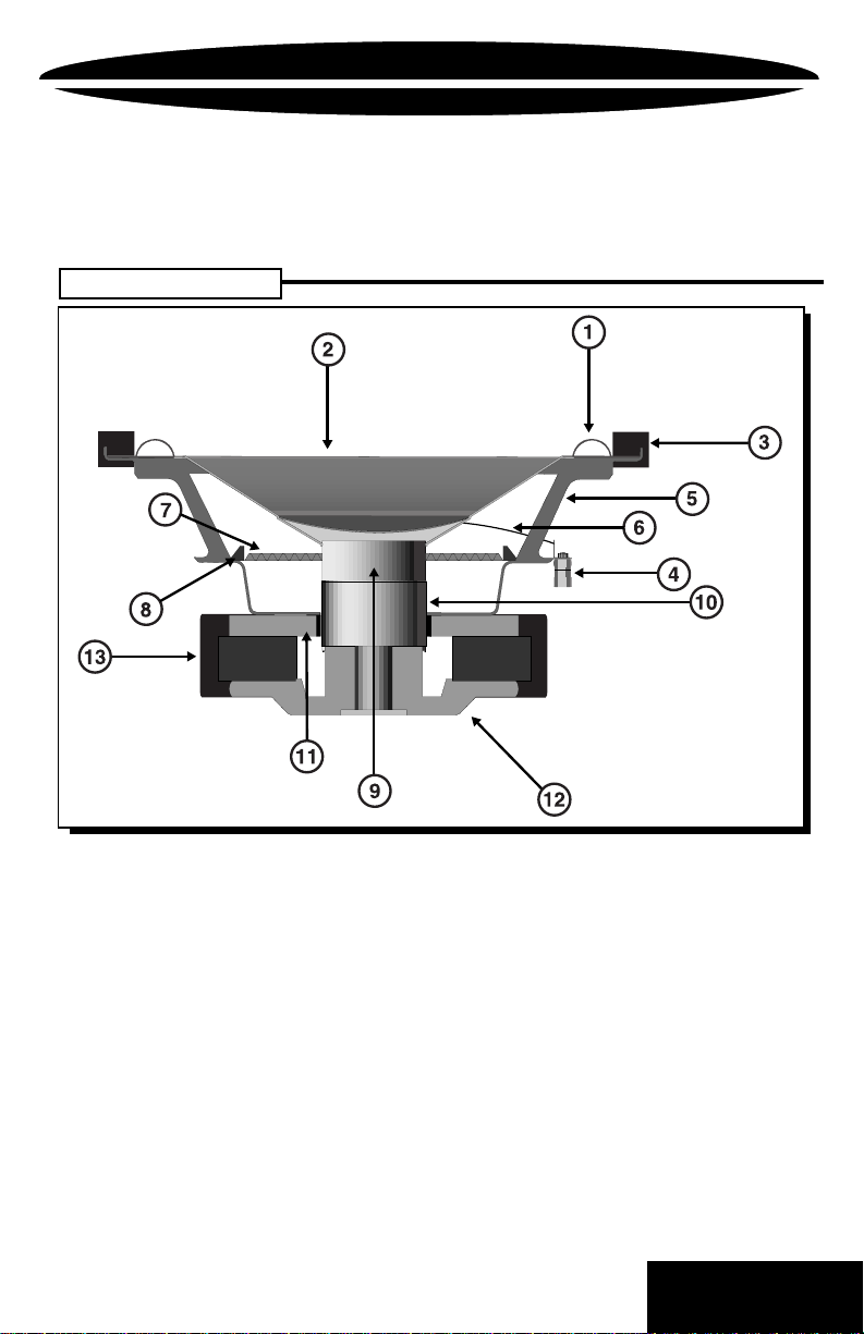
C2 StructureC2 Structure
C2 Structure
C2 StructureC2 Structure
Po werClass
“Absolutely State of the Art”
1. Progressive Butyl Rubber Surround 2. Stepped PolyCarbon Cone
3. Butyl Rubber Flange Gasket 4. Gold Plated 12ga. Binding Post Terminals
5. Deep Draw Steel Basket 6. High Current Silver Plated Tinsel Leads
7. Flat Spider 8. Spider Clamp
9. TIL Voice Coil Former 10. Long Wind 4 Layer Voice Coil
11. 10mm Frontplate 12. Integrated Backplate / Extended Pole
13. Protective Magnet Cover
Included in this manual are a number of sample enclosure drawings.
They are by no means the only enclosures to use, but rather a starting
point in the right direction. To determine the correct enclosure for your
needs many factors need to be addressed (amount of power , vehicle,
placement, crossover, etc.) Therefore, as always,
PrecisionPower
recommends that your subwoofer be installed by an Authorized
PowerClass
Dealer.
1
BACK T O CONTENTS
Page 4
POWERCLASS
PC8 C2
Subwoofer
PC8 C2
Normal Power Handling 150 W rms
Voice Coil Diameter 2” / 50.8mm
Voice Coil Type / Former 4 Layer/TIL
Resonant Frequency 32 Hz
Qts-Total Damping 0.49
Qms- Mechanical Damping 9.20
Qes- Electromagnetic Damping 0.518
Vas- Equivalent Compliance Volume .80cuft / 22.78 liter
DC Resistance of V.C. 3.6W / 6.8W
Sensitivity (SPL at 1W) 87.57 dB
Xmax (Linear Excursion) ±.343" / 8.72 mm
Peak to Peak Excursion ±.629" / 16.00 mm
Mms- Total Mass 2.34oz / 66.35 g
Sd- Piston Area .230sqft / 0.0214 sqm
Bl- Magnet Product 9.26 Tm
Cone Material Carbon Poly
Basket Material Stamped Steel
Net Weight 5.80 lbs / 2.63kg
Dimensions 8.09” dia. X 4.375” H
Mounting Hole Diameter 7.375” /185mm
Mounting Depth 4.00" /102mm
Displacement .04 cuft / 1.13 liter
PC8 C2
SPL 1: 1.31cu.ft. Bandpass F3: 49Hz Fo: 60Hz
Specifications
205mm dia. X 110mm H
Enclosure Recommendations
.61 Sealed/.7 Ported, 3"Dia x 5.5"L Port
SPL 2: .75 cu.ft. Ported F3: 40Hz Fo: 43Hz
3"Dia x 11"L Port
General Use 1: .75 cu.ft. Ported F3: 40Hz Fo: 43Hz
3"Dia x 11"L Port
General Use 2: .5 cu.ft. Ported F3: 46Hz Fo: 47Hz
2"Dia x 6"L Port
Audiophile 1: .75 cu.ft. Sealed F3: 48Hz
1) 4"Dia x 7.75"L Port
Audiophile 2: .5 cu.ft. Sealed F3: 49Hz
See page 6 for examples of dimensions for these enclosures.
2
BACK T O CONTENTS
Page 5
POWERCLASS
PC10 C2
Subwoofer
PC10 C2
Normal Power Handling 300W rms
Voice Coil Diameter 2” / 50.8mm
Voice Coil Type / Former 4 Layer/TIL
Resonant Frequency 25.24Hz
Qts-Total Damping 0.38
Qms- Mechanical Damping 6.95
Qes- Electromagnetic Damping 0.40
Vas- Equivalent Compliance Volume 2.4 cuft / 68.14 liter
DC Resistance of V.C. 3.6W / 6.8W
Sensitivity (SPL at 1W) 89.64 dB
Xmax (Linear Excursion) ±.393" / 9.97mm
Peak to Peak Excursion ±.679" / 17.25mm
Mms- Total Mass 3.37oz / 95.73g
Sd- Piston Area .372sqft / 0.0346 sqm
Bl- Magnet Product 11.74 Tm
Cone Material Carbon Poly
Basket Material Stamped Steel
Net Weight 8.68 lbs / 3.94 kg
Dimensions 10.07” dia. X 5.185” H
Mounting Hole Diameter 9.25” / 232mm dia.
Mounting Depth 4.80" / 122mm
Displacement .065 cuft / 1.84 liter
PC10 C2
Specifications
(256mm dia. X 132mm H)
Enclosure Recommendations
SPL 1: 1.0 cu.ft. Bandpass F3: 50Hz Fo: 75Hz
.36 Sealed/.62 Ported, 4"Dia x 6.5"L Port
SPL 2: .75 cu.ft. Ported F3: 43Hz Fo: 47Hz
3"Dia x 8.9"L Port
General Use 1: 1.0 cu.ft. Ported F3: 38Hz Fo:42Hz
3"Dia x 8.25"L Port
General Use 2: .75 cu.ft. Ported F3: 43Hz Fo: 47Hz
3"Dia x 8.9"L Port
Audiophile 1: 1.0 cu.ft. Ported F3: 38Hz Fo:42Hz
3"Dia x 8.25"L Port
Audiophile 2: .75 cu.ft. Sealed F3: 51Hz
See page 8 for examples of dimensions for these enclosures.
3
BACK T O CONTENTS
Page 6

POWERCLASS
PC12 C2
Subwoofer
PC12 C2
Normal Power Handling 300W rms
Voice Coil Diameter 2” / 50.8mm
Voice Coil Type / Former 4 Layer/TIL
Resonant Frequency 21.64Hz
Qts-Total Damping 0.41
Qms- Mechanical Damping 5.41
Qes- Electromagnetic Damping 0.44
Vas- Equivalent Compliance Volume 5.31cuft / 150.37 liter
DC Resistance of V.C. 3.6W / 6.8W
Sensitivity (SPL at 1W) 90.67 dB
Xmax (Linear Excursion) ±.393" / 9.97mm
Peak to Peak Excursion ±.67" / 17.00mm
Mms- Total Mass 4.46oz / 126.59g
Sd- Piston Area .555sqft / 0.0511 sqm
Bl- Magnet Product 11.87 Tm
Cone Material Carbon Poly
Basket Material Stamped Steel
Net Weight 8.92lbs / 4.04kg
Dimensions 12.0” dia. X 5.78” H
Mounting Hole Diameter 11.00” / 280mm
Mounting Depth 5.5" / 140mm
Displacement .075 cuft / 2.12 liter
PC12 C2
Specifications
305mm dia. X 147mm H
Enclosure Recommendations
SPL 1: 2.3 cu.ft. Bandpass F3: 53Hz Fo: 70Hz
.6 Sealed/1.7 Ported, 2) 4"Dia x 4.5"L Ports
SPL 2: 1.25 cu.ft. Ported F3: 42Hz Fo: 45Hz
4"Dia x 10.0"L Port
General Use 1: 1.75 cu.ft. Ported F3: 37Hz Fo: 40Hz
4"Dia x 8.5"L Port
General Use 2: 1.9 cu.ft. Bandpass F3: 45Hz Fo: 68Hz
.7 Sealed/1.2 Ported, 2) 4"Dia x 8.5"L Ports
Audiophile 1: 1.25 cu.ft. Sealed F3: 44Hz
Audiophile 2: 2.5 cu.ft. Ported F3: 31Hz Fo: 35Hz
4"Dia x 7.5"L Port
See page 10 for examples of dimensions for these enclosures.
4
BACK T O CONTENTS
Page 7

POWERCLASS
PC15 C2
Subwoofer
PC15 C2
Normal Power Handling 300W rms
Voice Coil Diameter 2” / 50.8mm
Voice Coil Type / Former 4 Layer/TIL
Resonant Frequency 31Hz
Qts-Total Damping 0.34
Qms- Mechanical Damping 1.21
Qes- Electromagnetic Damping 0.47
Vas- Equivalent Compliance Volume 3.83cuft / 108.43 liter
DC Resistance of V.C. 3.6W / 6.8W
Sensitivity (SPL at 1W) 90.51 dB
Xmax (Linear Excursion) ±.383" / 9.72mm
Peak to Peak Excursion ±.679" / 17.25mm
Mms- Total Mass 5.87oz / 166.15g
Sd- Piston Area .920sqft / 0.0855 sqm
Bl- Magnet Product 12.91 Tm
Cone Material Carbon Poly
Basket Material Stamped Steel
Net Weight 11.32 lbs / 5.13kg
Dimensions 15.16” dia. X 7.20” H
Mounting Hole Diameter 13.75” / 347mm dia.
Mounting Depth 6.85" / 173mm
Displacement .09 cuft / 2.56liter
PC15 C2
Specifications
(385mm dia. X 183mm H)
Enclosure Recommendations
SPL 1: 5.0 cu.ft. Bandpass F3: 47Hz Fo: 65
1.5 Sealed/3.5 Ported, 2) 6"Dia x 5.0"L Ports
SPL 2: 2.0 cu.ft. Ported F3: 44Hz Fo: 37Hz
4"Dia x 9.0"L Port
General Use 1: 3.5 cu.ft. Ported F3: 35Hz Fo: 35Hz
4"Dia x 4.5"L Port
General Use 2: 3.5 cu.ft. Bandpass F3: 40Hz Fo: 65
1.5 Sealed/2.0 Ported, 6"Dia x 4.0"L Ports
Audiophile 1: 2.5 cu.ft. Sealed F3: 41Hz
Audiophile 2: 2.0 cu.ft. Sealed F3: 44Hz
See page 10 for examples of dimensions for these enclosures.
5
BACK T O CONTENTS
Page 8
POWERCLASS
PC8 C2
Subwoofer
Basic Working Dimensions for the
Outer Diameter 8.09” / 205mm
Mounting Hole Diameter 7.375” /185mm
Mounting Depth (from bottom of top ring) 4.00" /102mm
Speaker Displacement .04 cuft / 1.13 liter
PC8 C2
PC8 C2
Sealed Enclosures
Net Volume Internal Dimensions (see page 15)
.33 cubic feet 14.25”L x 8.5”W x 5.25”D
.5 cubic feet 16”L x 9.75”W x 6”D
.6 cubic feet 16.75”L x 10.25”W x 6.5”D
Ported Enclosures
Net Volume Internal Dimensions (see page 17)
.33 cubic feet 14”L x 9”W x 5.375”D
Port Tuned to 50Hz 2"Dia x 8.5" Long Port
.5 cubic feet 14”L x 9”W x 5.625”D
Port Tuned to 47Hz 2"Dia x 6.0" Long Port
PC8 C2
.75 cubic feet 19”L x 11.75”W x 7.25”D
Port Tuned to 42Hz 3"Dia x 11.0" Long Port
PC8 C2
Low Gain .6 cu.ft. Sealed 10"L x 11.5"W x 10.125"C1
33Hz to 81Hz .35 cu.ft. Ported 10"L x 11.5"W x 5.375"C2
Medium Gain .35 cu.ft. Sealed 12"L x 8.5"W x 6.5"C1
43Hz to 94Hz .34 cu.ft. Ported 12"L x 8.5"W x 6"C2
High Gain .61 cu.ft. Sealed 17"L x 10.25"W x 6.5"C1
49Hz to 74Hz .7 cu.ft. Ported 17"L x 10.25"W x 7.125"C2
* Port must run through the sealed chamber in this enclosure.
Bandpass Enclosures
Net Volume Internal Dimensions (see page 19)
Port Tuned to 55 Hz 3"Dia x 15.0" Long Port*
Port Tuned to 65Hz 3"Dia x 10.75" Long Port*
Port Tuned to 60Hz 3"Dia x 5.0" Long Port
6
BACK T O CONTENTS
Page 9

POWERCLASS
PC8 C2
Subwoofer
PC8 C2
PC8 C2
Sealed RESPONSE CURVE
*ACTUAL IN-CAR RESPONSE CURVE WILL VARY BASED ON CAR TYPE, WOOFER LOADING, AND ENCLOSURE DESIGN.
Ported RESPONSE CURVE
*
*
PC8 C2
*ACTUAL IN-CAR RESPONSE CURVE WILL VARY BASED ON CAR TYPE, WOOFER LOADING, AND ENCLOSURE DESIGN.
Bandpass RESPONSE CURVE
*ACTUAL IN-CAR RESPONSE CURVE WILL V ARY BASED ON CAR TYPE, WOOFER LOADING, AND ENCLOSURE DESIGN.
7
*
BACK T O CONTENTS
Page 10

POWERCLASS
PC10 C2
Subwoofer
Basic Working Dimensions for the
Outer Diameter 10.07” / 256mm
Mounting Hole Diameter 9.25” / 232mm dia.
Mounting Depth (from bottom of top ring) 4.80" / 122mm
Speaker Displacement .065 cuft / 1.84 liter
PC10 C2
PC10 C2
Sealed Enclosures
Net Volume Internal Dimensions (see page 15)
.5 cubic feet 16”L x 10”W x 6.125”D
.75 cubic feet 18”L x 11.25”W x 7.0”D
1.0 cubic feet 20”L x 12.5”W x 7.375”D
Ported Enclosures
Net Volume Internal Dimensions (see page 17)
.75 cubic feet 18.5”L x 11.5”W x 7.0”D
Port Tuned to 47Hz 3"Dia x 9.0" Long Port
1.0 cubic feet 20”L x 12”W x8”D
Port Tuned to 42Hz 3"Dia x 8.25" Long Port
PC10 C2
1.25 cubic feet 21.75”L x 13”W x 8.25”D
Port Tuned to 38Hz 3"Dia x 8.0" Long Port
PC10 C2
Low Gain .84 cu.ft. Sealed 18.75"L x 11.5"W x 7.25"C1
33Hz to 85Hz .63 cu.ft. Ported 18.75"L x 11.5"W x 5.25"C2
Medium Gain .60 cu.ft. Sealed 17.0"L x 10.5"W x 6.5"C1
39Hz to 94Hz .60 cu.ft. Ported 17.0"L x 10.5"W x 6.375"C2
High Gain .36 cu.ft. Sealed 12.0"L x 12.0"W x 5.125"C1
50Hz to 101Hz .62 cu.ft. Ported 12.0"L x 12.0"W x 8.125"C2
Bandpass Enclosures
Net Volume Internal Dimensions (see page 19)
Port Tuned to 53Hz 3"Dia x 8.25" Long Port
Port Tuned to 60Hz 3"Dia x 6.25" Long Port
Port Tuned to 71Hz 4"Dia x 7.5" Long Port
8
BACK T O CONTENTS
Page 11
POWERCLASS PC10 C2
Subwoofer
PC10 C2
PC10 C2
Sealed RESPONSE CURVE
*ACTUAL IN-CAR RESPONSE CURVE WILL VARY BASED ON CAR TYPE, WOOFER LOADING, AND ENCLOSURE DESIGN.
Ported RESPONSE CURVE
*
*
PC10 C2
*ACTUAL IN-CAR RESPONSE CURVE WILL VARY BASED ON CAR TYPE, WOOFER LOADING, AND ENCLOSURE DESIGN.
Bandpass RESPONSE CURVE
*ACTUAL IN-CAR RESPONSE CURVE WILL VARY BASED ON CAR TYPE, WOOFER LOADING, AND ENCLOSURE DESIGN.
9
*
BACK T O CONTENTS
Page 12

POWERCLASS
PC12 C2
Subwoofer
Basic Working Dimensions for the
Outer Diameter 12.0” / 305mm
Mounting Hole Diameter 11.00” / 280mm
Mounting Depth (from bottom of top ring) 5.5" / 140mm
Speaker Displacement .075 cuft / 2.12 liter
PC12 C2
PC12 C2
Sealed Enclosures
Net Volume Internal Dimensions (see page 15)
1.0 cubic feet 20”L x 12”W x 7.75”D
1.25 cubic feet 21.25”L x 13.25”W x 8.125”D
1.5 cubic feet 22.5”L x 14”W x 8.625”D
Ported Enclosures
Net Volume Internal Dimensions (see page 17)
1.25 cubic feet 22.75”L x 14”W x 7.5”D
Port Tuned to 45Hz 4"Dia x 10.0" Long Port
1.75 cubic feet 24.75”L x 15”W x 8.75”D
Port Tuned to 40Hz 4"Dia x 8.5" Long Port
PC12 C2
2.50 cubic feet 27.25”L x 17”W x 9.75”D
Port Tuned to 35Hz 4"Dia x 7.5" Long Port
PC12 C2
Low Gain .94cu.ft. Sealed 15"L x 15"W x 7.75"C1
32Hz to 103Hz .8 cu.ft. Ported 15"L x 15"W x 6.625"C2
Medium Gain .7 cu.ft. Sealed 15"L x 15"W x 6.0"C1
45Hz to 98Hz 1.2 cu.ft. Ported 15"L x 15"W x 10.125"C2
High Gain .6 cu.ft. Sealed 15"L x 15"W x 5.125"C1
53Hz to 95 Hz 1.7 cu.ft. Ported 15"L x 15"W x 13.5"C2
Bandpass Enclosures
Net Volume Internal Dimensions (see page 19)
Port Tuned to 60Hz 4"Dia x 8.375" Long Port
Port Tuned to 68Hz 2) 4"Dia x 8.5" Long Ports
Port Tuned to 70Hz 2) 4"Dia x 4.5" Long Ports
10
BACK T O CONTENTS
Page 13

POWERCLASS
PC12 C2
Subwoofer
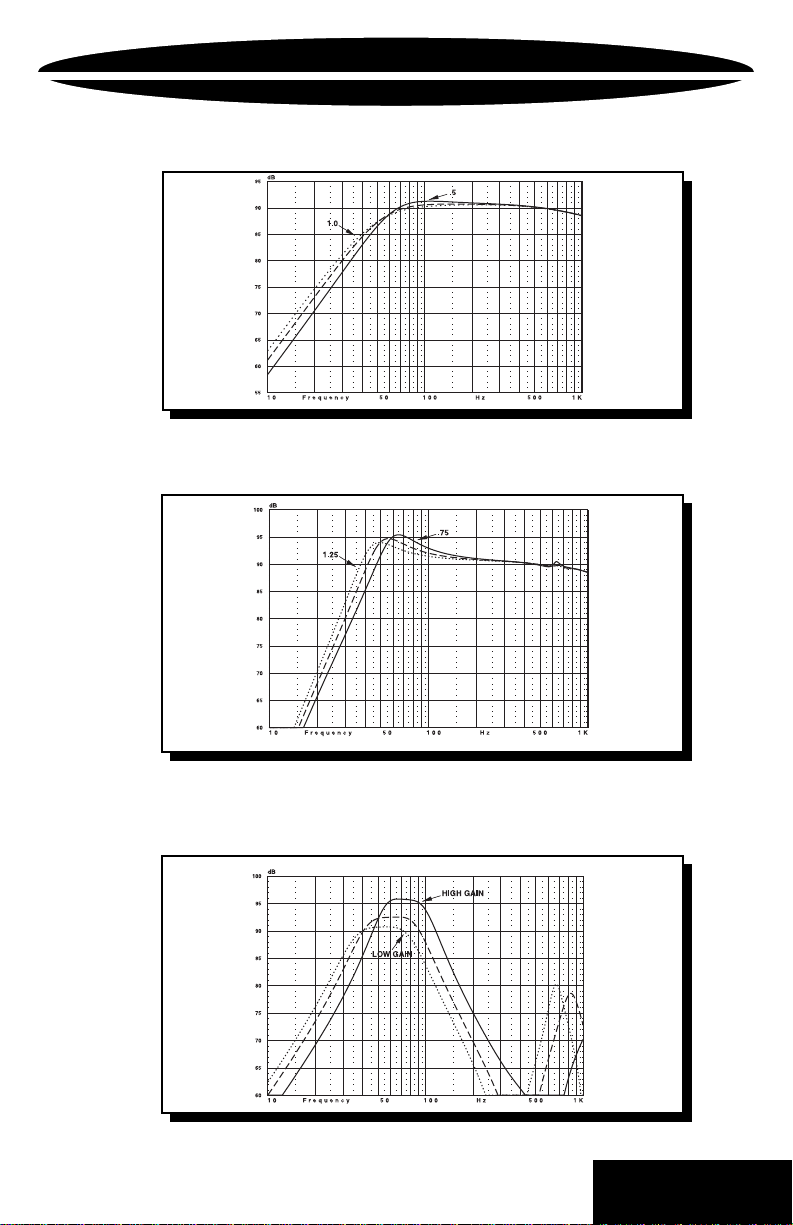
PC12 C2
PC12 C2
Sealed RESPONSE CURVE
*ACTUAL IN-CAR RESPONSE CURVE WILL V ARY BASED ON CAR TYPE, WOOFER LOADING, AND ENCLOSURE DESIGN.
Ported RESPONSE CURVE
*
*
PC12 C2
*ACTUAL IN-CAR RESPONSE CURVE WILL V AR Y BASED ON CAR TYPE, WOOFER LOADING, AND ENCLOSURE DESIGN.
Bandpass RESPONSE CURVE
*ACTUAL IN-CAR RESPONSE CURVE WILL VARY BASED ON CAR TYPE, WOOFER LOADING, AND ENCLOSURE DESIGN.
11
*
BACK T O CONTENTS
Page 14

POWERCLASS PC15 C2
Subwoofer
Basic Working Dimensions for the
Outer Diameter 15.157” / 385mm
Mounting Hole Diameter 13.75” / 350mm
Mounting Depth (from bottom of top ring) 6.85" / 174mm
Speaker Displacement .09 cuft / 2.67 liter
PC15 C2
PC15 C2
Sealed Enclosures
Net Volume Internal Dimensions (see page 15)
1.5 cubic feet 22.5”L x 14”W x 8.75”D
2.0 cubic feet 25”L x 15.25”W x 9.5”D
2.5 cubic feet 26”L x 16.5”W x 10.5”D
Ported Enclosures
Net Volume Internal Dimensions (see page 17)
2.0 cubic feet 25.75”L x 16”W x 9”D
Port Tuned to 37Hz 4"Dia x 9.0" Long Port
3.5 cubic feet 30”L x 18.5”W x 11.25”D
Port Tuned to 35Hz 4"Dia x 4.5" Long Port
PC15 C2
5.0 cubic feet 33”L x 21”W x 12.75”D
Port Tuned to 30Hz 4"Dia x 4" Long Port
PC15 C2
Low Gain 2.0 cu.ft. Sealed 16.5"L x 16.5"W x 13.25"C1
31Hz to 108Hz 1.5 cu.ft. Ported 16.5"L x 16.5"W x 10"C2
Medium Gain 1.5 cu.ft. Sealed 16.5"L x 16.5"W x 10"C1
40Hz to 108Hz 2.0 cu.ft. Ported 16.5"L x 16.5"W x 13.5"C2
High Gain 1.5 cu.ft. Sealed 18"L x 16"W x 9.5"C1
47Hz to 92Hz 3.5 cu.ft. Ported 18"L x 16"W x 21.125"C2
Bandpass Enclosures
Net Volume Internal Dimensions (see page 19)
Port Tuned to 60Hz 2) 3"Dia x 10.25" Long Ports
Port Tuned to 65Hz 2) 4"Dia x 8.5" Long Ports
Port Tuned to 65Hz 1) 6"Dia x 1.75" Long Port
12
BACK T O CONTENTS
Page 15

POWERCLASS
PC15 C2
Subwoofer
PC15 C2
PC15 C2
Sealed RESPONSE CURVE
*ACTUAL IN-CAR RESPONSE CURVE WILL VARY BASED ON CAR TYPE, WOOFER LOADING, AND ENCLOSURE DESIGN.
Ported RESPONSE CURVE
*
*
PC15 C2
*ACTUAL IN-CAR RESPONSE CURVE WILL V ARY BASED ON CAR TYPE, WOOFER LOADING, AND ENCLOSURE DESIGN.
Bandpass RESPONSE CURVE
*ACTUAL IN-CAR RESPONSE CURVE WILL V ARY BASED ON CAR TYPE, WOOFER LOADING, AND ENCLOSURE DESIGN.
13
*
BACK T O CONTENTS
Page 16

SEALED ENCLOSURE
Building a Sealed Enclosure:
1. Build a sealed enclosure with internal L x W x D as specified for
2. Using the supplied template, trace the appropriate circle and
3. Cut the speaker hole from the baffle board with a router,
4. Place the woofer in the opening which you have cut in the
5. Run an appropriate length of wire into the enclosure, leaving
6. Vacuum out any wood shavings and dust from the inside of the
7. Connect the wires to the woofer observing the proper polarity,
8. Install the woofer into the enclosure using #8 or larger wood
your woofer (See recommended enclosures for your woofer). Use
3/4” thick MDF for the enclosure. Be sure to use wood glue and
silicone to ensure your enclosure is sealed properly, as air leaks
will affect the performance of your subwoofer.
mounting hole pattern for your PowerClass C2 subwoofer on the
baffle board. (See diagram)
using a guide or template whenever possible. Use a jig saw only
if a router is not available.
baffle to check the fit.
enough length to comfortably install the wires to the terminals on
the woofer before placing the speaker into its mounting hole. Use
a terminal cup whenever possible.
enclosure. (Failure to do so may void your warranty.) Loosely
fill the box half way with polyester fiberfill.
positive and negative terminals. Strip away the insulation of
the wire about 1/4" and install the wires into the terminal posts.
screws (not supplied)
9. Once the enclosure is complete, it is time to connect the speaker
10. Finally, sit back and enjoy the incredible enhancement
wire coming from the subwoofer enclosure to your amplifier.
Check that you use the proper wire for consistent polarity,
positive and negative. (Refer to your amplifier owner’s manual.)
your new PowerClass C2 subwoofer brings to your audio
system.
14
BACK T O CONTENTS
Page 17

SEALED ENCLOSURE
Sealed Speaker Diagram
Internal dimensions should be calculated to determine the correct box
volume. Be sure to allow for speaker displacement and extra bracing (if
used).
15
BACK T O CONTENTS
Page 18

PORTED ENCLOSURE
Building a Ported Enclosure:
1. Build a ported enclosure with internal dimensions of LxWxD as
2. Using the supplied template, trace the appropriate circle and
3. Cut the speaker and port holes from the baffle board with a
4. Locate the port material that you are going to use, and cut to
5. Place the woofer into the hole which you have cut in the baffle to
6. Run an appropriate length of wire into the box, leaving enough
7. Vacuum out any wood shavings and dust from the inside of the
8. Connect the wires to the woofer observing the proper polarity,
9. Once the box is complete, it's time to connect the speaker wire
10. Finally, sit back and enjoy the incredible enhancement your new
specified for your woofer (See recommended enclosures for
your woofer). Use 3/4” thick MDF for the enclosure. Be sure to
use wood glue and silicone at all joints to ensure your enclosure
is sealed properly. Air leaks will affect the performance of your
subwoofer, even in a ported enclosure.
mounting hole pattern for your PowerClass C2 subwoofer on the
baffle board. Be sure to offset the woofer to one side to leave
room for the port in the baffle. (See Diagram)
router, using a guide or template whenever possible. Use a jig
saw only if a router is not available.
length. When installing the port, make sure you have a
clearance of at least one port diameter from the end of the port
to the inside wall of the box. Round over the inside edges of
both ends of the port with a router or file to minimize port noise.
check the fit.
to comfortably install the wires to the woofer terminals before
placing the speaker into its mounting hole. Use a terminal cup
whenever possible.
enclosure. (Failure to do so may void your warranty.) Line the
enclosure with a polyester fiberfill blanket or fiberglass insulation
about 1” thick.
positive and negative terminals. Strip away the insulation of
the wire about a 1/4" and install the wires into the terminal posts
coming from the subwoofer enclosure to your amplifier. Check
that you use the proper wire for consistent polarity, positive and
negative. (Refer to your amplifier owner’s manual.)
PowerClass C2 subwoofer brings to your audio system.
16
BACK T O CONTENTS
Page 19

PORTED ENCLOSURE
Ported Enclosure Diagram
Internal dimensions should be calculated to determine the correct enclosure
volume. Be sure to allow for speaker displacement, extra bracing (if used),
and port displacement (only the length of the port that is INSIDE the
enclosure). It may be necessary to angle the port to fit your design. To
calculate the displacement of the port: (Outside) Radius2 x 3.14 x Length of
the port that is inside the enclosure.
17
BACK T O CONTENTS
Page 20

BANDPASS ENCLOSURE
Building a Bandpass Enclosure:
1. Using 3/4" thick MDF, cut out all the panels to build a divided
2. Using the supplied template, trace the appropriate circle and
3. Cut the speaker and port holes from the baffle board with a router,
4. Locate the port material which you are going to use, and cut it to the
5. Assemble the enclosure, using wood glue and silicone at all joints to
6. Place the woofer into the hole which you have cut in the baffle to
7. Run an appropriate length of wire into the enclosure, leaving enough
8. Vacuum out any wood shavings and dust from the inside of the
9. Connect the wires to the woofer observing the proper polarity,
10. Install the woofer into the enclosure using #8 or larger wood screws.
11. Attach the removable cover to the enclosure, ensuring that there are
enclosure with internal dimensions of LxWxC1 and C2 as specified for
your woofer (See recommended enclosures for your woofer).
mounting hole pattern for your PowerClass C2 subwoofer on the baffle
board.
using a guide or template whenever possible. Use a jig saw only if a
router is not available.
appropriate length. When installing the port, make sure you have a
distance of at least one port diameter from the end of the port to the
inside wall of the enclosure. Round over the inside edges of both ends
of the port with a router or file to minimize port noise.
ensure your that enclosure is sealed properly. Air leaks will affect the
performance of your subwoofer even in ported enclosures. Leave one
panel removable for access to the woofer.
check the fit.
to comfortably install the wires to the terminals on the woofer before
placing the speaker into its mounting hole. Use a terminal cup
whenever possible.
enclosure. (Failure to do so may void your warranty.) Then, line the
ported side of the enclosure with a polyester fiberfill blanket or
fiberglass insulation about 1” thick, and loosely fill the sealed side of
the enclosure half way with polyester fiberfill.
positive and negative terminals. Strip away the insulation of
the wire about a 1/4" and install the wires into the terminal posts.
no air leaks.
12. Once the box is complete, it's time to connect the speaker wire coming
13. Finally, sit back and enjoy the incredible enhancement your new
from the subwoofer enclosure to your amplifier. Check that you use the
proper wire for consistent polarity, positive and negative.
(Refer to amplifier owner’s manual.)
PowerClass C2 subwoofer brings to your audio system.
18
BACK T O CONTENTS
Page 21

BANDPASS ENCLOSURE
Bandpass Enclosure Diagram
P
O
W
E
R
CL
A
S
S
M
T
Internal dimensions should be calculated to determine the correct enclosure
volume. Be sure to allow for speaker displacement, extra bracing (if used),
and port displacement (only the length of the port that is INSIDE the
enclosure). If the port is very long, it may be necessary to run the port
through the sealed chamber into the ported chamber. To calculate the
displacement of the port: (Outside) Radius2 x 3.14 x Length of the port that
is inside the enclosure.
19
BACK T O CONTENTS
Page 22

Additional Information
Our dealers are trained to achieve the highest level of performance from
our products. If you are installing your new subwoofers on your own and
need assistance, please call your local
PrecisionPower
Technical Service Department at
1-800-62-POWER.
PowerClass
dealer or
Thanks again for choosing
PowerClass
.
NOTE: Abuse and/or Installation Error:
to, burnt voice coils (blackened, no continuity, melted adhesives, coil separated from
the former, etc.), punctured or damaged surrounds, broken speaker terminals, non-
PrecisionPower
damaged back plates. Speakers submitted with any of the above will be considered out
of warranty.
modifications, bent, chipped, or broken frames, ripped spiders, or
PrecisionPower
20
defines abuse as, but not limited
BACK T O CONTENTS
Page 23

WARRANTY
Three-Year Limited U.S.A. Warranty
This warranty gives you specific legal rights, and you may also have other rights which vary from
state to state. PrecisionPower warrants its products to be free from defects in materials and
workmanship under normal use and service for a period of three (3) years from the date of
original purchase when the unit is installed by an Authorized Dealer. Non-Authorized Dealer
installed products carry a one (1) year parts and ninety (90) days labor limited warranty. The
extent and conditions of Limited Warranty are as follows:
1. Authorized Dealer Installed Products: PrecisionPower will either repair or replace at no charge,
to the original purchaser, any unit which PrecisionPower’s examination discloses to be defective
and under warranty, provided the defect occurs within three (3) years from the date of original
purchase when the unit is installed by an Authorized Dealer and the product is returned immediately to PrecisionPower. This warranty is not transferable.
2. Non-Authorized Dealer Installed Products: PrecisionPower will either repair or replace at no
charge, to the original purchaser, any unit which PrecisionPower’s examination discloses to be
defective and under warranty, provided the defect occurs within ninety (90) days from the date of
purchase and the product is returned immediately to PrecisionPower. Warranty claims beyond
ninety (90) days for Non-Authorized Dealer Installed Products will be for parts only and will
extend for one (1) year from the date of purchase. This warranty is not transferable.
3. The date of purchase and proof of Authorized Dealer Installation of a PrecisionPower product
must be established by an original sales receipt which must accompany the article being returned for warranty work.
4. This warranty shall NOT apply to any PrecisionPower product found to have the original factory serial number removed or defaced. All products received (by PrecisionPower) for in warranty or out of warranty repair, with their original serial numbers removed or defaced, will NOT be
repaired and will be returned to sender, freight collect. Refer to original packaging for the serial
number of your component speakers.
5. The provisions of this warranty shall not apply to any PrecisionPower product used for a
purpose for which it is not designed, which has been repaired or altered in any way , or which has
been connected, installed, or adjusted other than in accordance with the instructions furnished in
PrecisionPower’s owner’s manual. Nor shall this warranty apply to any part which has been
subject to misuse, neglect, or accident.
6. PrecisionPower does not authorize any other persons to assume any other liability in connection with its products. THIS WARRANTY IS THE ONLY EXPRESS WARRANTY MADE BY
PRECISIONPOWER APPLICABLE T O ITS PRODUCTS. ANY IMPLIED WARRANTY OR MERCHANTABILITY OR FITNESS FOR A PARTICULAR PURPOSE APPLICABLE TO
PRECISIONPOWER PRODUCTS IS LIMITED IN DURATION TO THE DURATION OF THIS
LIMITED WARRANTY. PRECISIONPOWER SHALL NOT BE LIABLE FOR THE INCIDENTAL,
CONSEQUENTIAL, OR COMMERCIAL DAMAGES RESUL TING FROM THE BREACH OF THIS
WRITTEN WARRANTY. Some states or provinces do not allow the exclusion or limitation of
incidental or consequential damages or limitations on how long an implied warranty lasts; so the
above limitations or exclusions may not apply to you.
7. Y our product will be serviced on an in-warranty basis within the warranty period for the correction of warranted defects. If improper operation of your PrecisionPower product should occur,
contact your Authorized Dealer for assistance with the return and factory repair of your PrecisionPower
product. If an Authorized Dealer is not available, return the unit including your name, telephone
number, return address, a copy of your sales receipt, and a description of the problem to:
PrecisionPower,Inc.
Service Department
4829 S. 38th Street
Phoenix, AZ 85040-2964
TO RETURN PRECISIONPOWER PRODUCTS OUT OF W ARRANTY : Return the unit, postage
prepaid, in the original protective carton. Please include a description of the problem and, if
desired, a request for an estimate of repair costs. Unless a request for an estimate is included,
the unit will be repaired as necessary. Please contact PrecisionPower Customer Service at 1800-62-POWER for questions concerning out of warranty repair charges. Repaired unit will be
returned with an itemized statement, C.O.D.
BACK T O CONTENTS
 Loading...