

Page 1

POWERCLASS
PC2100 / PC2200 / PC2300 OWNER’S MANUAL
™
CONTENTS
(click on a topic to view)
CONGRATULATIONS
FEATURES / SPECIFICATIONS
INSTALLATION
WIRING
WIRING (continued)
POWER / GROUND
SPEAKER WIRING
END PLATE DIAGRAM
INPUTS
QBASS / CROSSOVER
AMPLIFIER ADJUSTMENTS
TROUBLE SHOOTING
SYSTEM DIAGRAM ONE
SYSTEM DIAGRAM TWO
SYSTEM DIAGRAM THREE
SYSTEM DIAGRAM FOUR
BLOCK DIAGRAM
WARRANTY
Page 2
Congratulations and thank you.....
for choosing
proudly design, engineer and manufacture audio products at our facility in
Phoenix, Arizona. Our award winning engineering team utilizes innovative
technology to consistently deliver Absolutely State of the Art
sound quality, reliability, and value. This
our commitment to offer you unparalleled versatility and quality for years of
dependable service and listening enjoyment.
PrecisionPower
audio epuipment. At
PrecisionPower
PrecisionPower
TM
performance,
product reflects
we
Service
Do not attempt to service
Performing exploratory surgery on your audio equipment yourself
will void the warranty. Many parts of your
are custom built to our specifications. Our factory parts are not
made available to anyone else nor are they for sale. Our goal
is to make sure that your
sound as good as the day it was purchased. Contact your
authorized
service through
PrecisionPower
PrecisionPower
PrecisionPower
PrecisionPower
dealer about obtaining any warranty
.(See Warranty inside back cover)
products yourself.
PrecisionPower
product will always
gear
FOR YOUR RECORDS:
Model
Serial Number
Purchase Date
Caution!
The extended use of a high powered audio system may
result in hearing loss or damage. While
systems are capable of
incredible accuracy, they are also designed for you to
enjoy at more reasonable le v els all of the sonic subtleties
created by musicians. Please obser ve all local sound
ordinances.
"Concert Level"
PrecisionPower
volumes with
BACK TO CONTENTS
Page 3
Adaptive MOSFET Switching Power Supply
Fully Complimentary Darlington Output Stage
AP III
Protection Circuitry
QBASS
Two Way 90 Hz Crossover with Line Outputs
Balanced Differential Input Stage
High Voltage Input Capability with Input Attenuation Switch
Gold Plated RCA Input and Output Connectors
PowerLock
Mixed Mono/Stereo Operation
Three Year Warranty when installed by an Authorized
Completely Designed And Handcrafted In The USA
Specifications
Power Bandwidth: 4.5 Hz - 100 kHz
Total Harmonic Distortion: 0.02 %
Input Topology: Balanced Differential
Input Sensitivity: 120mv - 12 volts RMS
Input Impedance: 10k Ohms
Load Impedance (stereo) 2 - 8 Ohms
Load Impedance (bridged) 4 - 8 Ohms
Supply Voltage 11 - 15 volts
Damping Factor >500
Slew Rate >50 V/µS
QBASS
Idle Current: .7 Amps
™
Bass Boost
™ Equalization Up To +12dB Boost @ 40 Hz
FEATURES / SPECIFICATIONS
Speaker and Power Wire Connectors
PrecisionPower
Dealer
Dimensions
Length PC2100 - 7.45"
PC2200 - 9.72"
PC2300 -11.72"
Height All - 2.25"
Width All - 8.9"
Crossover Specifications
Crossover Point: 90 Hz
Choice of High Pass or Low Pass at RCA outputs while opposite
is available at the Speaker Outputs.
PC2100 - Third Order (18 dB/octave), Butterworth alignment fixed at 90 Hz.
PC2200/PC2300 - Fourth Order (24 dB/octave), Linkwitz-Riley alignment
fixed at 90 Hz.
Continuous Output Power
PC2100
25 WRMS x 2 @ 4Ω per channel
50 WRMS x 2 @ 2Ω per channel
100 WRMS x 1 @ 4Ω bridged
PC2200
50 WRMS x 2 @ 4Ω per channel
100 WRMS x 2 @ 2Ω per channel
200 WRMS x 1 @ 4Ω bridged
PC2300
75 WRMS x 2 @ 4Ω per channel
150 WRMS x 2 @ 2Ω per channel
300 WRMS x 1 @ 4Ω bridged
1
BACK TO CONTENTS
Page 4
INSTALLATION
Tools/Parts needed for Installation (not supplied)
Small flat blade screwdriver
Phillips Screwdriver (#2 or medium sized)
Wire cutters
Wire strippers
4 - #6 round head screws, and 1 - #8 sheet metal screw
(or nut, bolt, and star washer)
2 - Ring connectors (large enough to accommodate your
method of grounding)
In-line fuse or circuit breaker - see fuse chart below
Power and ground wire - see Power Wire Calculator on page 3
Speaker wire - 16 gauge or larger
Grommets (sized to work with the power wire you plan to use
in your installation)
Tube of silicone sealant
Fuse requirements
Amplifier Maximum Fuse Rating
PC2100
PC2200
PC2300
You will need to install an in-line fuse or circuit breaker in
the power wire within 18" of the battery. This fuse or circuit
breaker is to protect your vehic le from fire in case the po wer
wire shorts to the vehicle body. If you are only using one
amplifier, use the fuse rating indicated in this chart. If you are
using more than one amplifier, add up the fuse ratings for all the
amplifiers. This sum is the rating for your fuse or circuit breaker.
You may also want to add a power distribution block near your
amplifiers to keep the wiring tidy.
2
20 Amp
30 Amp
35 Amp
BACK TO CONTENTS
Page 5
WIRING
The following is a basic f ormula to be used as a guide to determine amperage
draw. A 50% amplifier efficiency rating is used as an average. Your new
POWERCLASS
be less. This formula is to be used as a guideline. Using wire of a larger
gauge can only improve the current transfer of your system. Do not use
smaller gauge wire.
Total RMS output x 2 = Total Input Wattage
™
amplifier is more efficient, other amplifiers will probably
Total Input Wattage
Supply V oltage
Example: A
POWERCLASS
= Current Draw (in Amps)
™
2200 amplifier has two channels at 50 watts
per channel RMS rating into 4 Ohms (50 + 50 = 100). You would use the
formula in the following way:
100W x 2 = 200W
200W
= 16.7A Total amperage draw.
12V
If the same amplifier is driven into a 2 Ohm stereo or 4 Ohm mono load,
double its 4 Ohm RMS rating. All
double their power at this load.
100W x 2 x 2 = 400W
400W
= 33.3A Total amperage draw.
12V
If you are using more than one amplifier, add up the total amperage draw
for all of them and choose the appropriate gauge based on the grand total.
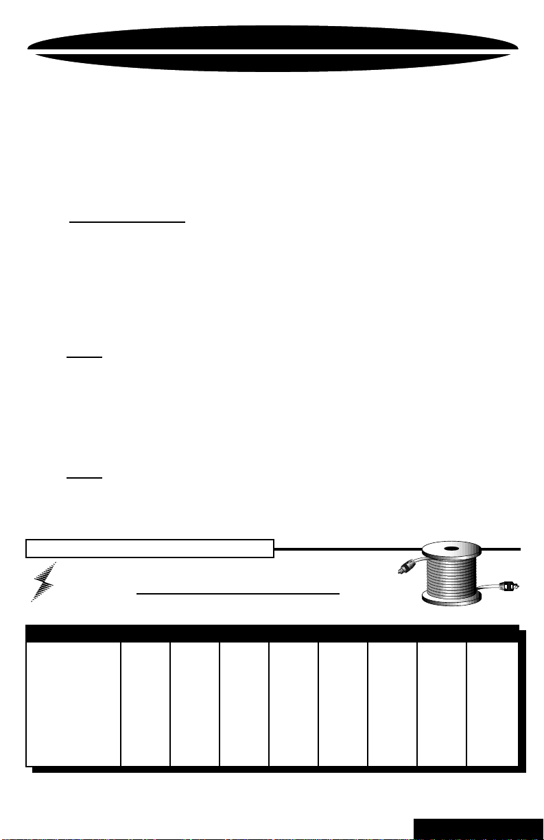
Power Wire Calculator
Recommended MINIMUM Gauge
POWERCLASS
™
amplifiers will effectively
Total Current Draw Length Of Wire To Be Run
( in Amps) Up to 4ft. 4 to 7ft. 7 to 10ft. 10 to 13ft. 13 to 16ft. 16 to 19ft. 19 to 22ft. 22 to 28ft.
0-20 14 12 12 10 10 8 8 8
20-35 12 10 8 8 6 6 6 4
35-50 10 8 8 6 6 4 4 4
50-65 8 8 6 4 4 4 4 2
65-85 6 6 4 4 2 2 2 0
85-105 6 6 4 2 2 2 2 0
105-125 4 4 4 2 2 0 0 0
125-150 2 2 2 2 0 0 0 00
(
NOTE: The ground wire should be the same gauge as the power wire.
3
BACK TO CONTENTS
Page 6
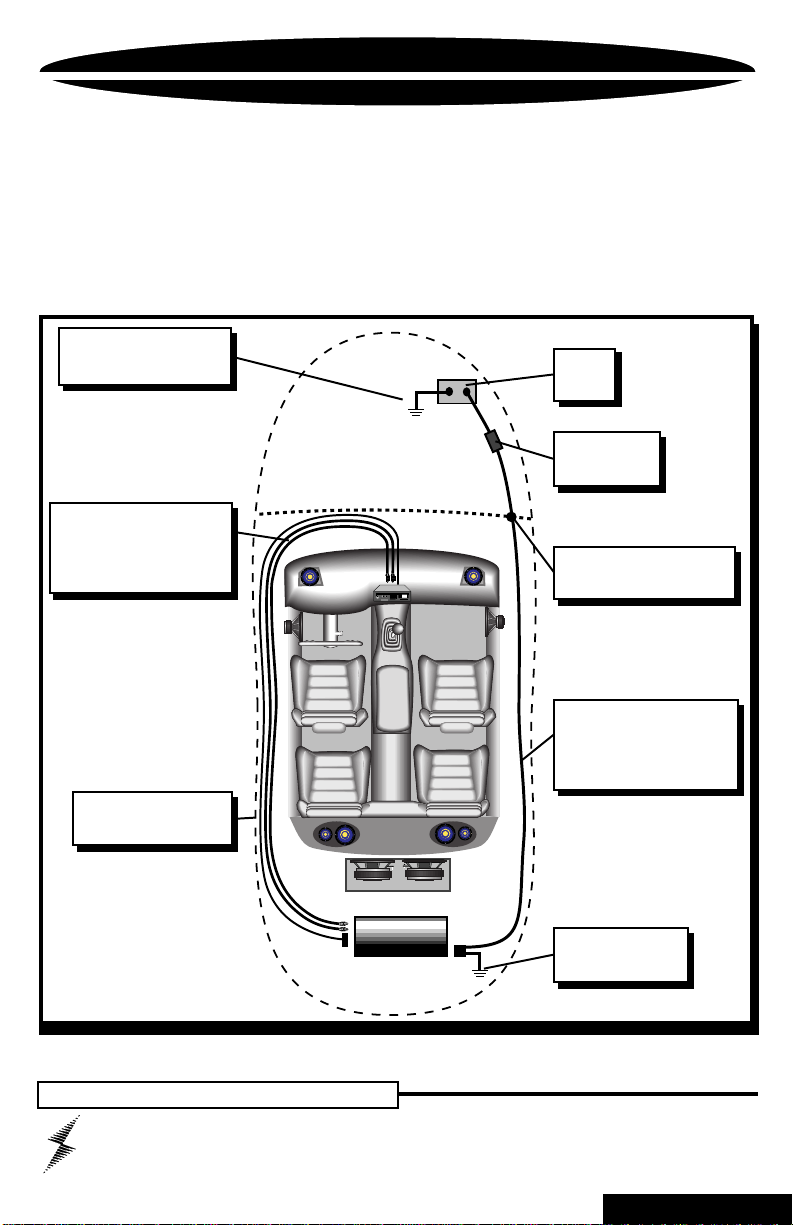
WIRING
Before beginning, disconnect the negative (-) terminal of the
battery prior to working on the positive (+) terminal to prevent
a short to ground. This is important, unless you want to spend
the rest of your life with a nickname like
"Sparky,"
Reconnect the negative terminal only after all connections have
been made.
Factory Ground wire may
need to be replaced if it is
frayed or broken.
Run signal cables (RCAs)
and remote turn-on lead
down the opposite side of
the vehicle from the power
wire to avoid radiated noise.
eject
123
4
Trk 1
5
876
BASS
TREBLE
MARKET
PPI
INGDPT
BALANCE
TRACK
VOLUME
RIGHT
FOWARD
REVERSE
LEFT
or
Positive
Battery
Terminal
Fuse must be
installed within
18" of battery
Drill a hole in the firewall
and use a rubber grommet
to keep wire from shorting.
"Smokey."
Avoid sharp edges that
could chafe through the
insulation.
Warning!
Run the cables under the
carpet near the side of the
vehicle. Be careful not to
drill or screw into the wires
when you replace the trim.
Firmly attach Amp
Ground Wire to solid
metal (see page 5).
Fuse must be installed within 18" of battery
4
BACK TO CONTENTS
Page 7

POWER / GROUND
Locate an area near the amplifier(s) that is metal and clean an
area about the size of a quarter to bare metal. Inspect the
area around and underneath to be sure you won't drill into wires,
brake or fuel lines, etc. Drill a pilot hole into the middle of this
area. Terminate the ground wire with a ring connector and attach
it to the bare metal using a #8 sheet metal screw and washer
or preferably, a bolt, nut and a star washer (not supplied). We
suggest crimping and soldering this connection. After the
connection is complete, coat the area (on both sides) with
silicone or some similar material to prevent rust from
developing on the bare metal.
POWER
Once you hav e run both the pow er and g round wires, it's time
to connect the cables to the amplifier . Cut off excess wire and,
using wire strippers, strip the ends of the power and ground
cables approximately 1/4 inch. Locate the
and ground connector (supplied). With a small flat bladed scre w
driver , loosen the screws before attempting to insert the cables.
Insert the wires into the appropriate hole, and tighten the
screws. Once the wires are secure, the
plugged into the amplifier.
Power/Ground
PowerLock
Connect to Amplifier
Designed and Handcrafted in the U.S.A.
Fastening screws
+
-
PowerLock
Power wires
PowerLock
may be
power
5
BACK TO CONTENTS
Page 8

SPEAKER WIRING
Using 16 gauge or larger, run the speaker wires from the
amplifier location through the vehicle to the speakers . Observe
the same precautions for routing these wires that you f ollo wed
for running the power and remote turn-on wires. Cut off e xcess
and, using wire strippers, strip 1/4 inch of insulation. Locate
the speaker/remote turn-on
PowerLock
connector. Loosen
the four outer screws on the underside of the connector . Insert
the speaker leads into the end. Check to be sure you've
maintained proper polarity before securing each wire.
Speaker
Power
Lock
Connector
Right Speaker negative
Right Speaker positive
Remote turn on
Left Speaker positive
Left Speaker negative
Speaker/Remote
6
Po werLock
BACK TO CONTENTS
Page 9

INPUTS
Plug in the
RCA leads
from your
head unit
here (see
page 8).
ENDPLATE DIAGRAM
HP/LP Switch
This switch
is used to
select whether
the amplifier
will provide a
highpass (in) or
lowpass (out)
signal to the
speakers.
(see page 9).
GAIN Control
Use this control to
match the output
level of the head
unit to the input of
the amplifier
(see page 10).
Speaker/Remote Connector
After connecting remote and
speaker wires, plug in the
PowerLock
connector here.
INPUTS
L R
HP/LP
INPUT Attenuation
For use with high
level inputs
(4V up to 12V).
QBASS™ Control
Rotate clockwise
to boost 40Hz up
to 12dB.
INPUT -12dB
GAIN
-
+
QBASS
0 12
OUTPUTS
L
R
L- L+ REM R+ R-
XOVER
ON/OFF
XOVER ON/OFF Button
Push this button in to turn
on the 90Hz crossover to
the speaker outputs (see
page 9).
RCA OUTPUTS
Left and Right RCA
outputs provide either
high or low pass signal to
another amplifier. This
signal will be low pass if
you've selected high pass
for the speaker outputs,
and vice versa.
7
BACK TO CONTENTS
Page 10

t
INPUTS
There are two sets of RCA jacks on the front end of your
amplifier. The RCA cables from your head unit go in the set
labeled INPUTS. If your head unit doesn't have RCA outputs
don't worry. Simply add a set of RCA plugs (available at your
dealer) to your front or rear set of speaker leads (see drawing
below), plug them into the input jacks, and push in the INPUT
ATTENUATION button.
SOURCE Headunit
eject
VOLUME
WARNING:
If you are using a source unit with bridged high powered (or
"floating ground") speaker outputs, a suitable high to low level adapter must be
used. If you are unsure about your head unit see your local PrecisionPower
dealer or call 1-800-62Power
123
4
Trk 1
5
BASS
LEFT
876
TREBLE
BALANCE
RIGHT
MAR KET
PPI
ING DPT
TRACK
FOWARD
REVERSE
(+) Positive
LEFT input
(-) Negative
(+) Positive
RIGHT inpu
(-) Negative
Balanced Differential Inputs
This circuitry is capable of eliminating noise radiated into your
signal cables by up to 40dB. This is equivalent to a noise
reduction of approximately one hundred times what the noise
level would be without this circuitry . It provides all the benefits
of a true 'balanced' line without the need of any special cables
(see diagram below). This type of input works with any
conventional RCA cable .
music
signal and ground
music
noise
noise
noise
(+)
( + =)
( )
music noise
(+)
( - = 0 )
( )
noise cancels
8
music
and noise
music
NO noise
BACK TO CONTENTS
Page 11

QBASS
™
and CROSSOVER Operation
QBASS
™
For extra BOOM from your system, we've developed the
QBASS
™
to the left of the RCA outputs, and allows you to add up to
12dB of boost centered at 40Hz by rotating the control
clockwise.
CAUTION:
strong subwoofers. 12dB is a lot of bass boost and could
damage full range speakers.
Crossover
Your new
built in to provide system fle xibility without the added e xpense
and installation of an outboard crossover. The
third-order Butterworth type 18dB per octave crossover, and
the
PC2200
type, 24dB per octave phase correlated crosso ver f or a tighter
sound. The speaker outputs of your amplifier are high pass or
low pass according to the HP/LP switch adjacent to the inputs .
You would choose low pass (switch out) to use this amp for
subwoofers, or choose high pass (switch in) to use this amp
for full range speakers . The RCA outputs are controlled by the
same HP/LP switch, but are alw a ys the inv erse of the speak er
output crossover. If the HP/LP switch is out (LP) the RCA
outputs will be high pass, and if the HP/LP switch is in (HP) the
RCA outputs will be low pass. In addition, the speaker outputs
can be all pass (no crossover) by setting the Xover ON/OFF
switch to the off (out) position.
bass control circuit. The
+12dB
+6dB
0
20Hz
™
QBASS
should only be used in systems with
POWERCLASS
and
PC2300
40Hz 60Hz 80Hz 100Hz
™
amplifier has a 90Hz crossover
house a fourth-order Linkwitz-Riley
QBASS
QBASS
™
control is located
™
PC2100
has a
NOTE: The RCA outputs are alwa ys crossed over .The System
Diagrams beginning on page 12 show se veral w a ys to use the
internal crossover in your system.
9
BACK TO CONTENTS
Page 12

AMPLIFIER ADJUSTMENT
Adjusting The Amplifier Input Gain
1. Adjust all amplifier input gain controls to just above minimum
sensitivity (fully counterclockwise).
2. Using the cleanest source (CD), with music playing turn up
the head unit until you can hear distortion. No w turn it down a
bit until you cannot hear the distortion.
3. Increase the Amplifier gain (clockwise) until the onset of
audible distortion. Then decrease the gain to the point just
before the distortion starts. This setting minimizes bac kground
noise and prevents overload.
4. Repeat step 3 for any remaining amplifiers in the system.
Bridging
All two-channel
POWERCLASS
bridged into a 4 ohm mono output without switches or bridging
modules. This feature permits the creation of a mono channel
for a subwoofer or center channel.
Deriving the mono channel is accomplished by using the left
channel positive wire as the positive speak er wire and the right
channel negative wire as the negative speaker wire. It is
important that a minimum 4 ohms impedance is obser ved. If
the impedance drops significantly below 4 ohms while the
amplifier is wired in the bridged configuration, the amplifier's
protection circuitry (AP III) may engage.
Heatsink Cooling
The unique heatsink on your
been designed with fins on the inside of the aluminum mass.
This allows for the transfer
of heat from the circuitry to
the heatsink fins and out
through the vents in the
endplates. Be sure you
have ample space around
the amplifier for cooling, at
least 2" on all sides.
™
amplifiers are capable of being
POWERCLASS
10
™
amplifier has
BACK TO CONTENTS
Page 13

TROUBLE SHOOTING
NO SOUND Is the LED lit?
YES NO
Check Power and Remote turn-on wire
for voltage. Make sure Ground wire is
secure.
STILL NO SOUND - See your Authorized
or Call
SOUND IN ONE CHANNEL ONLY
Reverse left and right speakers by unplugging the speaker connector, turning it
over and plugging it back in.
SOUND IS NOW IN
OPPOSITE CHANNEL
Reverse RCA inputs
SOUND IS NOW IN
OPPOSITE CHANNEL
Reverse RCAs at head unit
SOUND IS NOW IN
OPPOSITE CHANNEL
Problem is in the head unit
1-800-62POWER
Problem is in the speaker or speaker
wire of the silent channel.
Problem is in the Amplifier. See your
local Authorized
or call
Problem is in the RCA cables
PrecisionPower
.
SAME CHANNEL
SAME CHANNEL
PrecisionPower
1-800-62POWER
SAME CHANNEL
Dealer
Dealer
.
AMPLIFIER SHUTS OFF
Short Circuit Protection engaged:
The amplifier will turn off and try to come back on immediately. The
amplifier will cycle like this indefinitely, with "blips" of sound each
time. If this is the case, check your speakers and wiring for low
impedance and short circuits.
Thermal Protection engaged:
The amplifier will turn off and several minutes later will come back
on. In this case, ensure that there is nothing blocking the normal
convective airflow of the amplifier. No obstruction should be within
2" of the amplifier on all sides.
11
BACK TO CONTENTS
Page 14

SYSTEM DIAGRAM
ONE
Source Unit
eject
123
4
Trk 1
5
876
BASS
TREBLE
MAR KET
PPI
BALANCE
VOLUME
LEFT
ING DPT
TRACK
RIGHT
FOWARD
REVERSE
Tweeter
Passive
Crossover
Passive
Crossover
Tweeter
MidRangeMidRange
POWER
CLASS™
Crossover Off
Passive
Crossover
Amplifier
Subwoofer
Mixed Mono Output
The ability to run stereo speakers while simultaneously running a mono
output from the same amplifier is accomplished by running the stereo
speakers normally and tapping into the appropriate wires for the "mixed
mono" channel (left channel positive for the positiv e speaker wire and right
channel negative for the negativ e speaker wire). Speaker impedance should
be no lower than 2 ohms on the stereo channels and 4 ohms on the mono
channel.
NOTE: Passive crossovers must be used for "mixed mono" operation.
Choose a low pass crossover around 100Hz for your subwoofer, then
choose a high pass crossover for your stereo channels. The high pass
crossover must be at the same or slightly higher frequency than the low
pass crossover to maintain the correct impedance. See your
dealer or call
1-800-62POWER
for more information about passive
PrecisionPower
crossovers.
12
BACK TO CONTENTS
Page 15

SYSTEM DIAGRAM
TWO
Source Unit
eject
123
4
Trk 1
5
876
BASS
TREBLE
MAR KET
PPI
BALANCE
VOLUME
LEFT
ING DPT
TRACK
RIGHT
FOWARD
REVERSE
Tweeter
Subwooofer
Passive
Crossover
POWER
POWER
CLASS™
Crossover Low Pass Output
CLASS™
Crossover off or Low Pass
Amplifier
Amplifier
Passive
Crossover
Tweeter
MidRangeMidRange
Subwoofer
13
BACK TO CONTENTS
Page 16

PSC-221
PAR-245
ByPass
L
Invert
L
in •
Non-inverted /
out •
Inverted /
Phase Shift Control
SYSTEM DIAGRAM
THREE
Source Unit
eject
123
4
Trk 1
5
876
BASS
TREBLE
MARKET
PPI
INGDPT
BALANCE
TRACK
VOLUME
RIGHT
FOWARD
REVERSE
LEFT
R
Input
L
R
Input Sensitivity
Rear
Output
L
R
Front
Output
L
LED Select
Precision
PAR-245
Volume
Power
Power
F
In-Clip
R
Fader
Defeat
Sub Low
Preamp/Equalizer
USA
Phase Shift Control
Made in
600
220
o
100
-ø
Right Phase
er
Pow
Power
600
Precision
220
PSC-221
o
100
-ø
Left Phase
Input
L
Power
Precision
ByPass
R
Invert
R
R
Ground
Remote
Active
Power
ByPass
1
2
3
4
Sub
Low Low-Mid
Made in USA
++++
+
Low-Mid
High-Mid
Treble
Power
Frequency Adjust
High-Mid
Treble
PAR-245
Rear OutputFront Output
Tweeter
Mid Range
POWER
CLASS™
High Pass at 90 Hz
Amplifier
Subwoofer
14
Tweeter
Mid Range
POWER
CLASS™
Low Pass at 90 Hz
Subwoofer
Amplifier
BACK TO CONTENTS
Page 17

PAR-245
SYSTEM DIAGRAM
FOUR
Source Unit
eject
123
4
Trk 1
5
876
BASS
TREBLE
MAR KET
PPI
VOLUME
LEFT
Input Sensitivity
4
Precision
PAR-245
Sub Low
Volume
Power
Power
F
In-Clip
R
Fader
Defeat
Sub Low Low-Mid
Preamp/Equalizer
25 Hz
Power
Precision
DEQ-230
Power
Input
stereo • out
mono • in
Output
L
R
Ground
Remote
L
R
BALANCE
2
3
High-Mid
50 Hz
b
d
2
-1
Power
ING DPT
TRACK
RIGHT
FOWARD
REVERSE
R
Input
L
R
Rear
Output
L
R
Front
Output
L
LED Select
1
Low-Mid
High-Mid
Made in USA
++++
+
Treble
PAR-245
200 Hz
100 Hz
b
d
2
1
+
b
d
2
-1
b
d
2
1
+
b
d
2
-1
b
d
2
1
+
63 Hz
b
31.5 Hz
-12d
12db
+
b
-12d
40 Hz
EQ
Defeat
Power
Frequency Adjust
Treble
USA
Made in
12.8 KHz
b
d
2
1
+
6.4 KHz
b
d
Third Octave Equalizer
2
-1
16 KHz
b
d
2
1
+
12db
+
3.2 KHz
b
d
2
b
-1
8 KHz
-12d
b
d
20 KHz
2
1
+
b
12d
+
1.6 KHz
b
d
2
-1
b
4 KHz
-12d
b
d
2
1
+
10 KHz
b
12d
+
800 Hz
b
d
2
+12db
-1
b
2 KHz
-12d
b
d
2
1
+
-12db
5 KHz
b
12d
+
400 Hz
b
d
2
-1
+12db
b
1 KHz
b
-12d
d
2
1
+
-12db
2.5 KHz
12db
+
b
d
2
-1
+12db
b
b
d
d
500 Hz
2
-12
1
+
-12db
b
12db
d
+
1.27 KHz
2
-1
b
+12db
250 Hz
-12d
b
12d
-12db
635 Hz
+
b
+12db
126 Hz
-12d
b
12d
-12db
+
320 Hz
b
+12db
-12d
b
12d
+
-12db
156 Hz
+12db
-12db
80 Hz
+12db
-12db
+12db
-12db
+12db
-12db
Tweeter
Mid Range
Subwoofer
POWER
POWER
DEQ-230
FRX-456
CLASS™
Crossover off
CLASS™
Crossover off
third octave EQ
Power
Precision
FRX-456
Inputs
L
L
combined
inputs • in
R
R
rear
front
Crossover
Amplifier
Amplifier
Four/Five/Six Way Electronic Crossover
344
192
112
752
344
152
344
7.4K
192
80
112
Tweeter
272
1.77K
172
80
92
118
Mid Range
492
70
56
Front
36
25
Mid Bass
264
16
22
10
+
46
Low Pass
7
_
+10
Sub Sonic
∞
Subwoofer
Low Pass Gain
Power
Power
Precision
Ground
Remote
Power
Mid Range Frequencies
Low Pass Frequencies
USA
Made in
+
_
752
344
152
Rear Fill Level
7.4K
80
Tweeter
1.77K
80
Rear
Mid Range
PSC-221
High Pass Frequencies
Phase Shift Control
Power
Power
600
Precision
220
PSC-221
o
100
-ø
Left Phase
Input
ByPass
L
L
Invert
L
ByPass
R
Invert
R
R
in •
Non-inverted /
out •
Ground
Inverted /
Remote
Active
Power
ByPass
Phase Shift Control
USA
Made in
600
220
o
100
-ø
Right Phase
Power
Precision
Tweeter
Mid Range
Subwoofer
POWER
CLASS™
Crossover off
Amplifier
15
BACK TO CONTENTS
Page 18

RCA
Output
High Pass
Low Pass
QBASS
™
AMP
AMP
High Pass
Low Pass
X-OVER ON/OFF
HP/LP SELECT
RCA
Output
RCA
Right
Input
DIF.
DIF.
RCA
Left
Input
- 12dB INPUT ATTENUATION
Right
Left
mute
mute
mute
GAIN
GAIN
mute
90Hz
90Hz
BLOCK DIAGRAM
16
BACK TO CONTENTS
Page 19

WARRANTY
Three-Year Limited U.S.A. Warranty
This warranty gives you specific legal rights, and y ou ma y also hav e other rights which vary from
state to state.
workmanship under normal use and service for a period of three (3) years from the date of
original purchase when the unit is installed by an Authorized Dealer. Non-Authorized Dealer
installed products carry a one (1) year parts and ninety (90) days labor limited warranty. The
extent and conditions of Limited Warranty are as follows:
1. A uthorized Dealer Installed Products:
to the original purchaser, any unit which
and under warranty, provided the defect occurs within three (3) years from the date of original
purchase when the unit is installed by an Authorized Dealer and the product is returned immediately to
2. Non-Authorized Dealer Installed Products:
charge, to the original purchaser, any unit which
defective and under warranty, provided the defect occurs within ninety (90) days from the date of
purchase and the product is returned immediately to
ninety (90) days for Non-Authorized Dealer Installed Products will be for parts only and will
extend for one (1) year from the date of purchase. This warranty is not transferable.
3. The date of purchase and proof of Authorized Dealer Installation of a PrecisionP o w er product
must be established by an original sales receipt which must accompany the article being returned for warranty work.
4. This warranty shall NOT apply to any
tory serial number removed or defaced. All products received (by
ranty or out of warranty repair , with their original serial numbers removed or defaced, will NO T be
repaired and will be returned to sender, freight collect. Refer to original packaging for the serial
number of your component speakers.
5. The provisions of this warranty shall not apply to any
purpose for which it is not designed, which has been repaired or altered in any way, or which has
been connected, installed, or adjusted other than in accordance with the instructions furnished in
PrecisionPower’ s
subject to misuse, neglect, or accident.
6. PrecisionPower does not authorize any other persons to assume any other liability in connection with its products. THIS WARRANTY IS THE ONLY EXPRESS WARRANTY MADE BY
PRECISIONPOWER APPLICABLE TO ITS PRODUCTS. ANY IMPLIED WARRANTY OR MERCHANTABILITY OR FITNESS FOR A PARTICULAR PURPOSE APPLICABLE TO
PRECISIONPOWER PRODUCTS IS LIMITED IN DURATION TO THE DURATION OF THIS LIMITED W ARRANTY. PRECISIONPOWER SHALL NO T BE LIABLE FOR THE INCIDENT AL, CONSEQUENTIAL, OR COMMERCIAL DAMAGES RESULTING FROM THE BREA CH OF THIS WRITTEN W ARRANTY. Some states or pro vinces do not allow the exclusion or limitation of incidental
or consequential damages or limitations on how long an implied warranty lasts; so the above
limitations or exclusions may not apply to you.
7. Y our product will be serviced on an in-warranty basis within the warranty period f or the correction of warranted defects. If improper operation of your
contact your Authorized Dealer for assistance with the return and factory repair of your
PrecisionPower
product. If an Authorized Dealer is not available, return the unit including your name, telephone
number, return address, a copy of your sales receipt, and a description of the problem to:
TO RETURN PRECISIONPOWER PR ODUCTS OUT OF WARRANTY: Return the unit, postage
prepaid, in the original protective carton. Please include a description of the problem and, if
desired, a request for an estimate of repair costs. Unless a request for an estimate is included,
the unit will be repaired as necessary. Please contact
800-62-POWER for questions concerning out of warranty repair charges. Repaired unit will be
returned with an itemized statement, C.O.D.
PrecisionPower
PrecisionPower
owner’s manual. Nor shall this warranty apply to any part which has been
warrants its products to be free from defects in materials and
PrecisionPower
PrecisionPower’ s
. This warranty is not transferable.
PrecisionPower
PrecisionPower
PrecisionPower,Inc.
Service Department
4829 S. 38th Street
Phoenix, AZ 85040-2964
will either repair or replace at no charge,
examination discloses to be defective
PrecisionPower’s
will either repair or replace at no
examination discloses to be
PrecisionPower
product found to have the original fac-
PrecisionPower
PrecisionPower
PrecisionPower
. Warranty claims beyond
PrecisionPower
product used for a
product should occur,
Customer Service at 1-
) for in war-
BACK TO CONTENTS
 Loading...