

Page 1

TM
CONTENTS
(click on a topic to view)
Congratulations System T uning
Features and Specifications System Tuning
Mounting Frequency Distribution
Mounting Frequency / Q Selection Code
Wiring Frequency / Q Selection Code
Wiring System One
Functions System Tw o
Functions System Three
System T uning T roubleshooting
System T uning Block Diagram
System T uning Warranty
PAR 245 5 Band Equalizer / Preamp OWNERS MANUAL POWER CLASS
Page 2
Congratulations and thank you.....
for choosing
proudly design, engineer and manufacture audio products at our facility in
Phoenix, Arizona. Our award winning engineering team utilizes innovative
technology to consistently deliver Absolutely State of the Art
sound quality, reliability, and value. This
our commitment to offer you unparalleled versatility and quality for years of
dependable service and listening enjoyment.
PrecisionPower
audio epuipment. At
PrecisionPower
PrecisionPower
TM
performance,
product reflects
we
Service
Do not attempt to service
Performing exploratory surgery on your audio equipment yourself
will void the warranty. Many parts of your
are custom built to our specifications. Our factory parts are not
made available to anyone else nor are they for sale. Our goal
is to make sure that your
sound as good as the day it was purchased. Contact your
authorized
service through
PrecisionPower
PrecisionPower
PrecisionPower
PrecisionPower
dealer about obtaining any warranty
.(See Warranty insde back cover)
products yourself.
PrecisionPower
product will always
gear
FOR YOUR RECORDS:
Model
Serial Number
Purchase Date
Caution!
The extended use of a high powered audio system may
result in hearing loss or damage. While
systems are capable of
incredible accuracy, they are also designed for you to
enjoy at more reasonable levels all of the sonic subtleties
created by musicians. Please observe all local sound
ordinances.
"Concert Level"
PrecisionPower
volumes with
BA CK TO CONTENTS
Page 3
FEATURES / SPECIFICATIONS
5 Band Parametric Equalizer
Preamp Line Driver
Choice of 16 Selectable Frequency/Q
Settings for Each Band
Front and Rear Outputs with Fader Control
Dual Selectable Illumination
Center-Detented Boost/Cut Controls
±15 dB Boost/Cut for Each Band
Defeat Switch
Gold-plated RCA Input and Output Connectors
PWM (Pulse Width Modulated) Power Supply
Independent L & R Input Gain Adjustments
Input Clip Indicator
Designed and Handcrafted in the U.S.A.
Specifications
Signal-to-Noise Ratio 110 dB
Total Harmonic Distortion (1 kHz, 1 VRMS) 0.002%
Boost/Cut Range
±
15 dB
Equalizer Center Frequencies and Q Values:
Band Frequency Q Value
Sub (30 - 66 Hz) 2.0 - 3.0
Low (90 - 300 Hz) 3.0 - 5.5
Low-Mid (430 - 900 Hz) 2.5 - 4.5
High-Mid (950 Hz - 4.6 kHz) 2.5 - 6.0
Treble (6 - 16 kHz) 1.3 - 3.3
Maximum Input Voltage (Flat) 10 VRMS
Maximum Output (10 kΩ Load) 10 VRMS
Frequency Response 3 to 100 kHz
Supply Voltage 9 - 15 VDC
Dimensions 4.60" L
6.75" W
0.95" H
1
BA CK TO CONTENTS
Page 4
Mounting
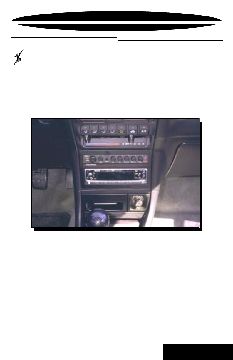
MOUNTING
To prevent damage to the
PAR-245
while driving, mount it in a
secure place. Choosing the appropriate location will depend
upon your vehicle and the complexity of your system design. Typical
mounting locations for your new
PAR-245
would be in the dash or
center console. Never mount the component in a location that would
subject it to immersion or exposure to water.
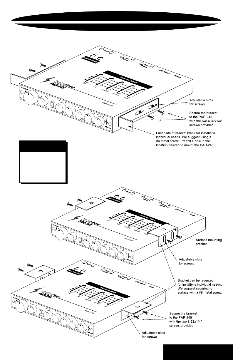
Once a location has been chosen, securely mount the
P AR-245
using
the two supplied brackets. There are two different sets of brackets
included with your
245
, as shown above. The other set is used to surface mount, as
P AR-245
. One set is used to flush mount the
P AR-
shown on the next page. The brackets are connected to the equalizer/
preamp by two 6-32 x 1/4" socket head cap screws. We have made
the brackets adjustable to compensate for the uniqueness of each
vehicle. Be Careful! Inspect the area underneath to be sure you are
not drilling into wires, etc. that could be damaged by the drill bit or
screws.
2
BA CK TO CONTENTS
Page 5
In-Clip
Dimensions
6.75"W
4.60" L
0.95"H
MOUNTING
RL
RL
RL
RL
RL
RL
In-Clip
++++
+
RL
RL
RL
In-Clip
++++
+
3
BA CK TO CONTENTS
Page 6
WIRING
eject
123
4
Trk 1
5
876
BASS
TREBLE
MARKET
PPI
INGDPT
BALANCE
TRACK
VOLUME
RIGHT
FOWARD
REVERSE
LEFT
+
F
++++R
Volume
Power
In-Clip
PAR-245
Defeat
Sub Low Low-Mid
Fader
High-MidTreble
NOTE
Before beginning, disconnect the negative (-) terminal of the
battery prior to working on the positive (+) terminal to prevent
a short to ground. This is important, unless you want to spend
the rest of your life with a nickname like
"Sparky ,"
or
"Smokey."
Reconnect the negative terminal only after all connections have
been made.
4
BA CK TO CONTENTS
Page 7
r
WIRING
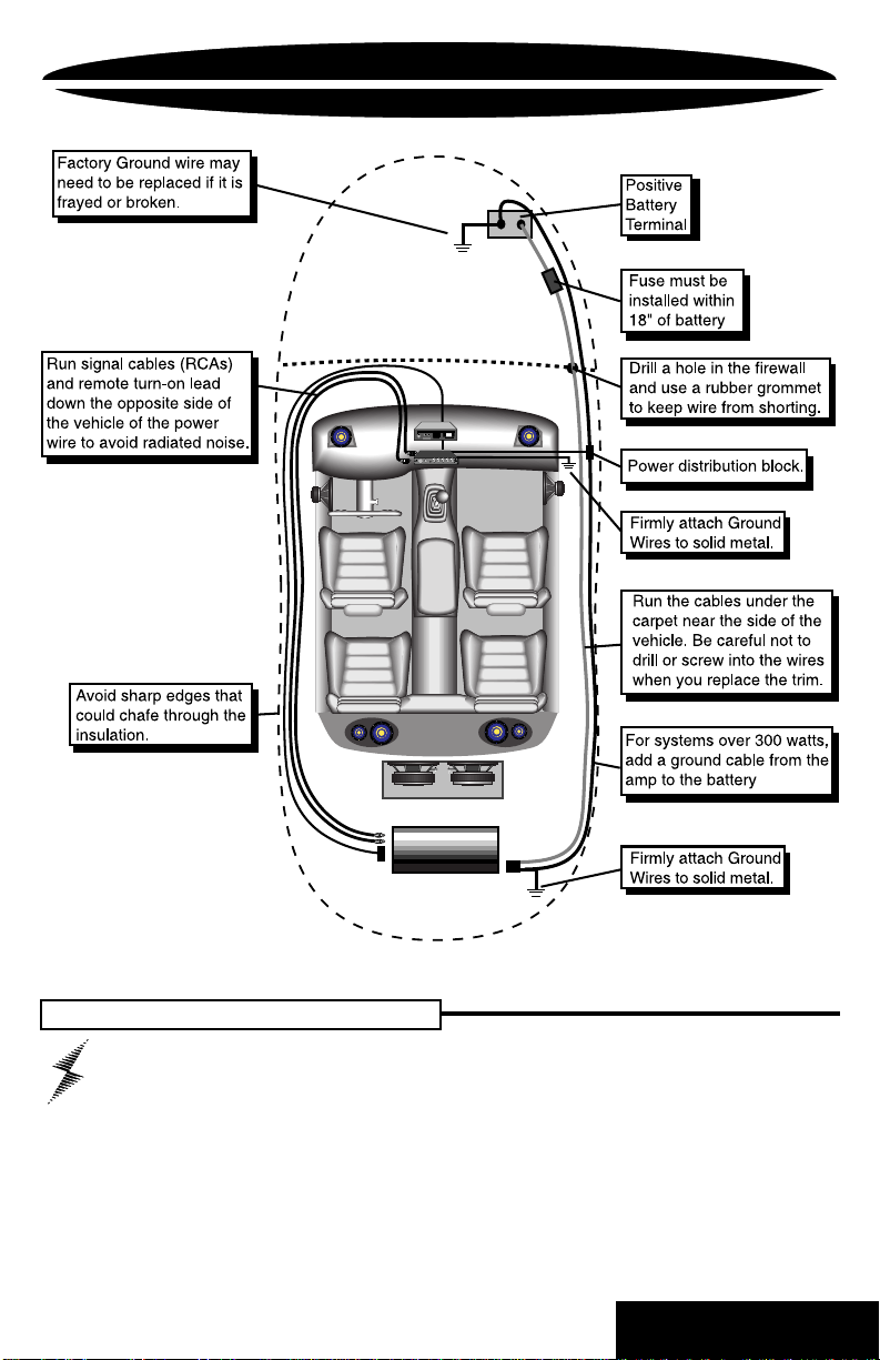
The next step is to connect the Power , Ground, and Remote wires to
your
PAR-245
. The power wire should run from the mounting location
through the vehicle to the battery or power distribution block. Avoid
sharp corners, creases, and sharp body parts. When passing through
any metal wall (i.e. firewall etc.), a grommet must be used to prevent
the wire from chaffing and shorting to ground.
The ground wire should be of the same gauge as the power wire. As
a rule of thumb, use as short a length of wire as possible.
Find a location near the equalizer that is metal (the floor is ideal) and
clean an area about the size of a quarter to bare metal. Drill a pilot
hole in the middle of this area. Be Careful! Inspect the area underneath
to be sure you are not drilling into wires, brake or fuel lines, etc.
Terminate the wire with a ring connector and attach it to the bare
metal using a #8 sheet metal screw and washer (not supplied). We
suggest crimping and/or soldering this connection. After the connection
is complete, coat the area with silicone or some similar material to
prevent rust from developing.
Finally, the remote wire needs to
run to the power antenna (or
Powerlock
Ground
Remote
Powe
amplifier remote) lead of the head
unit. This wire supplies a 12 volt
signal to the
PAR-245
when the
T/O
B+
main system is activated.
Once you have routed the power ,
ground, and remote wires through
the vehicle, it is time to connect the wires to the
PAR-245
. Be sure
that you have not reconnected the ground cable to the negative post
of the battery.
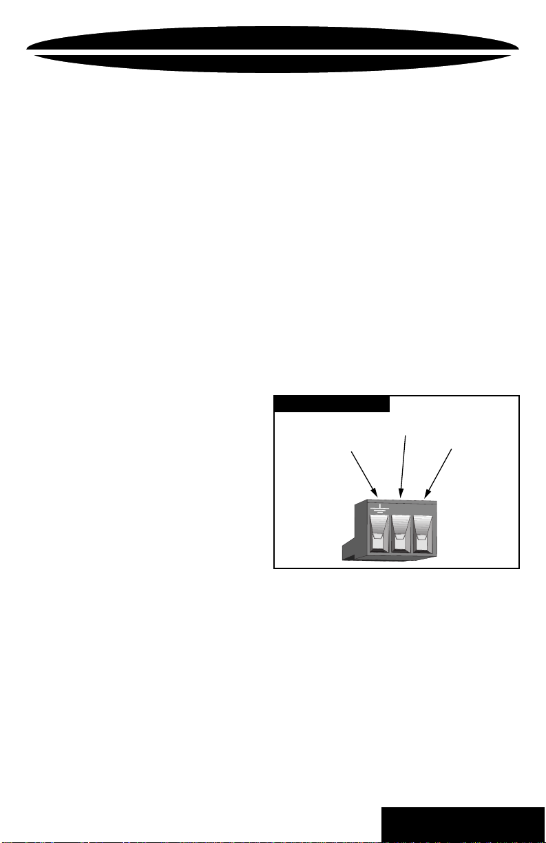
Cut off excess wire and, using wire strippers, strip the power , ground
and remote cables about 1/8 inch. Locate the power, ground, and
remote
Powerlock
connector (supplied). On the top of the connector
are three slotted screws. With a small flat-bladed screwdriver , loosen
the screws before attempting to insert the cables. After you have
inserted the stripped end of each cable into the connector, secure it
by tightening the associated screw. Check that each connection is
tight. If the wires are secure, the connector may be plugged into the
PAR-245
.
5
BA CK TO CONTENTS
Page 8

FUNCTIONS
1. Input
2. Rear Output
3. Front Output
4. LED Select
5. Power
6, 7. Left and Right Input Sensitivity
8. Frequency Adjust
Gold plated RCA inputs. Plug in the RCA cables from the source unit
here.
Gold plated RCA outputs. Plug in the RCA cables to your rear channel
amplifier here.
Gold plated RCA outputs. Plug in the RCA cables to your front channel
amplifier here.
Push this switch IN for Red Illumination, Leave it OUT for Green.
After connecting the Power, Ground and Remote wires, plug in the
PowerLock
Sets Left and Right input gain to match the output level from the
source unit. (See Page 8)
Set the Frequency/Q combination for each band with these
switches. See the Frequency/Q Selection Codes on pages 14 and 15.
connector here.
6
BA CK TO CONTENTS
Page 9

FUNCTIONS
+
++++
1
2
1. Power LED
Red light indicates power on.
2. Input Clip
Input-Clip indicator lights when the PAR-245 is overdriven. With the
source unit at 3/4 full volume, adjust the input sensitivity so that the light
blinks only on very loud material.
3. V olume
Leave the source unit at 3/4 full volume, and use this control as the
Master volume control.
4. Fader
Controls the output level to Front and Rear.
5. Defeat Switch
With the switch in the OUT position, the equalizer controls are bypassed.
Use this switch to compare the sound with and without equalization.
6. Sub
Subwoofer band (30 Hz - 66 Hz) Boost/Cut control.
7. Low
Low band (90 Hz - 300 Hz) Boost/Cut control.
3 4 5
876
109
8. Low-Mid
Low Midrange band (430 Hz - 900 Hz) Boost/Cut control.
9. High-Mid
High Midrange band (960 Hz - 4.6 kHz) Boost/Cut control.
10. T reble
Treble band (6 kHz - 16 kHz) Boost/Cut control.
7
BA CK TO CONTENTS
Page 10

SYSTEM TUNING
System Gain Adjustment
In order to achieve maximum signal-to-noise performance from
a high quality auto stereo system, it is desirable to use high
signal levels wherever possible in the interconnect cables. High signal
levels will reduce the effect of induced noise. The peak level of an
audio signal is usually determined by the clipping level of electronic
components. The following procedure should be used as a guide
before the system installation is completed.
Adjustment of source unit output and
1. Turn
PAR-245
volume control fully counterclockwise.
2. Turn source unit volume 1/2 to 3/4 of maximum.
3. Adjust all
PAR-245
input gains fully counterclockwise.
4. Play a CD or cassette. A loud music selection is desired.
5. Adjust the left input gain control clockwise until the
input clip LED lights. Then adjust the control
counterclockwise slightly until the LED doesn't light. This
setting will minimize system background noise and
prevents overloading the
6. Repeat Step 5 for the right input gain control.
There are separate left and right gain adjustments
for each input which allows left/right balance
adjustments.
Adjusting amplifier input gains:
1. Adjust gains to minimum sensitivity (fully
counterclockwise on the gain control of a
2. Turn the volume knob on the
3 o'clock position.
3. Increase the gain on the amplifier until the onset of
audible distortion.
4. Repeat step 3 for any remaining amplifiers in the
system.
PAR-245
PAR-245
PAR-245
input:
.
PPI
to the
amplifier .)
NOTE: In many multi-amplifier systems, the gain of some
amplifiers may need to be further decreased to
achieve tonal balance.
8
BA CK TO CONTENTS
Page 11

SYSTEM TUNING
Parametric Operation
The
PAR-245
Equalizer/Preamp puts an incredible amount of
control at your fingertips. Correctly adjusted, it can solve many
of the problems you will encounter along your road to perfect sound.
By following these guidelines, you will avoid common pitfalls in system
tuning and get your sound quickly dialed in. We recommend that you
use a Real T ime Analyzer (RTA) to speed things up, but it is possible
to tune your system without it.
It is important to understand what your equalizer actually controls to
be able to use it effectively . On the face of the
P AR-245
are five Boost/
Cut controls each corresponding to a range of frequencies. On the
top are the five sets of Frequency/Q Selection switches to adjust for
each Boost/Cut control on the front of the
PAR-245
(See the chart on
pages 14 and 15 for Frequency/Q selection.)
Q is an indication of how wide or narrow the adjusted bandwidth is. A
low Q will affect a wide range of frequencies around the selected
center frequency resulting in a gently curved shape, while a high Q
affects a narrow band resulting in a peaked shape as shown below.
9
BA CK TO CONTENTS
Page 12

SYSTEM TUNING
NOTE:
If you are using the
(like the
DEQ-230
or
PMQ-210
PAR-245
as well as another equalizer
) Go to step 11.
1) The first step is to locate a suitable source of “pink noise." A
good choice would be the current IASCA competition reference
disc. Also, some RTAs have a built-in pink noise source. Ideally,
the pink noise should play through your head unit, allowing you to
compensate for any frequency response changes caused by it, or
anything else, before the amplifiers.
2) Next, place the microphone from the RTA in the driver's seat at
approximately head level. Initially, set the analyzer to read at 3dB
per step, and set the speed of the RTA’s readout to medium. Turn
on your system and start the pink noise. Raise or lower the volume
until you can see all (or most) of your frequency response on the
RTA scale (a little above or below is OK). Make sure all of the
equalizer's frequency controls are centered and look at the RTA
screen.
3) Y ou are trying to achieve a target frequency response, or "curve"
that reflects your preference. Y ou might think that a perfectly straight
line would be best, but it really doesn't sound very good. Instead,
shoot for a curve that starts about 9 dB up at the low frequencies (25
Hz to about 100 Hz) dropping gently to 0 dB in the midrange (250
Hz to 3 kHz), then dropping gently to -9 dB at 16 kHz and 20 kHz.
RTA
06
PPI
12
09
06
03
00
03
09
12
40 50 63 80 100 125 160 200 250 315 400 500 630 800 1K 1.25K
25
31.5
THIRD OCTAVE REAL TIME SPECTRUM ANALYZER
1.6K
10
2K 2.5K3. 15K 4K 5K 6.3K 8K 10K 12.5K 16K 20K
BA CK TO CONTENTS
Page 13

SYSTEM TUNING
4) If electronic crossovers are used, any large frequency sections
corresponding to your crossover points that are low or high should
be brought in line using crossover level controls or amp gain
adjustments rather than the equalizer.
5) To begin, you will probably see several peaks and dips in your
RTA curve. Find the lowest offending frequency, and choose the
appropriate frequency range control on the top of the
PAR-245
.
Reading from left to right when looking at the face of your new
PAR-245
, the following are the frequency ranges;
BAND FREQUENCY
SUB 30 Hz - 66 Hz
LOW 90 Hz - 300 Hz
LOW-MID 430 Hz - 900 Hz
HIGH-MID 960 Hz - 4.6 kHz
TREBLE 6 kHz - 16 kHz
6) Looking at the Frequency/Q selection chart for the selected band,
set the switches on top of the
P AR-245
to the frequency that is closest
to the peak (or dip) and has the highest Q. T urn the Boost/Cut control
counterclockwise until the peak (clockwise to correct a dip) comes in
line with your desired curve. (See pages 14 & 15.)
7) When the center frequency of the original peak (or dip) has been
brought down to where you want it, you may see that surrounding
frequencies are still higher than you want them. Select the closest
frequency to the original peak (or dip) that has a lower Q, and see if
you now have a smooth line through that band. You may have to try a
number of Frequency/Q combinations to get the best results.
11
BA CK TO CONTENTS
Page 14

SYSTEM TUNING
8) Move to the next peak or dip, and repeat the process until you run
out of frequencies to adjust. Try to remove the peaks before filling the
dips. Periodically , while you are making adjustments, compare the new
curve you are making to the system in an unequalized state by using
the defeat switch on the front face plate of the
PAR-245
.
RTA
00
06
PPI
12
09
06
03
03
09
12
40 50 63 80 100 125 160 200 250 315 400 500 630 800 1K 1.25K
25
31.5
THIRD OCTAVE REAL TIME SPECTRUM ANALYZER
1.6K
2K 2.5K3. 15K 4K 5K 6.3K 8K 10K 12.5K 16K 20K
9) Play your favorite music. If the sound isn't what you're looking for,
go back to the pink noise and smoothly adjust your curve for more
bass, less midrange or whatever you think will correct the sound.
Remember that this is your system - don't let someone else tell you
how it should sound! When the sound is close to what you want, move
to step 10.
10) Play several different music tracks. If you hear an instrument, voice,
or other sound that is too loud, find the sound on the chart on page 14.
This will give you clues as to what frequencies need to be adjusted on
the
PAR-245
. (If you have already tuned using an RTA, this step is
icing on the cake.) Make one adjustment at a time, giving yourself
time to notice the changes.
11) If you are using another equalizer, like the
PMQ-210
using the other equalizer . This leaves the
, as well as the
PAR-245
, you should first tune the system
P AR-245
DEQ-230
or the
free to make wider
frequency adjustments, compensating for equalization differences
between Radio, Cassette, Video and Digital sources, like DAT and
CD. Select Frequency/Q combinations for each band near the center
of the frequency range, with a low Q.
12
BA CK TO CONTENTS
Page 15

FUNDAMENTAL NOTE
HARMONIC OR OVERTONE
FREQUENCY DISTRIBUTION
electric guitar
acoustic guitar
violin
cello
double bass
trumpet
french horn
trombone
tuba
soprano sax
tenor sax
clarinet
oboe
flute
piano
25 50
200 400 800 1.6 3.2 6.4 12.8 20K
100
synthesizer
female vocal range
male vocal range
tympani
kick drum
tom drum
snare drum
cymbals
electric bass
13
BA CK TO CONTENTS
Page 16

FREQUENCY/Q SELECTION CODES
14
BA CK TO CONTENTS
Page 17

FREQUENCY/Q SELECTION CODES
PAR-245 Frequency Controls
Use a small flat-bladed screwdriver to change the
Frequency/Q selection switches to the settings following the
System Tuning guidelines.
15
BA CK TO CONTENTS
Page 18

PAR-245
PMQ-210
Ten Band Parametric EQ
Preamp/Equalizer
FRX-456
SYSTEM ONE
Source Unit
eject
123
4
Trk 1
5
876
BASS
TREBLE
MAR KET
PPI
ING DPT
BALANCE
TRACK
VOLUME
RIGHT
FOWARD
REVERSE
LEFT
R
Input
L
R
Input Sensitivity
R
ear
O
utput
L
R
Front
Output
L
1
Frequency Adjust
2
3
4
Precision
PAR-245
Sub Low Low-Mid Treble
Volume
Power
Power
F
In-Clip
Fader
Input
attenuation
-12dB in
L
R
combined
inputs • in
Crossover
High-Mid
R
Made in USA
Defeat
Sub Low Low-Mid
++++
+
High-Mid Treble
PAR-245
1.95KHz-4.5Khz
z-1.25KHz
940H
HL
330Hz-1KHz
HL
160Hz-550Hz
Q
HL
80Hz-260Hz
Q
HL
41.5
40Hz-130Hz
Q
HL
41.5
Cut / Boost
z-70Hz
20H
Q
HL
41.5
Cut / Boost
Q
Power
Power
Precision
PMQ-210
Output
stereo•out
mono•in
R
Ground
Remote
Power
L
Power
Precision
FRX-456
_
Power
Inputs
L
L
R
R
rear
Ground
Remote
front
+12db-12db
41.5
Cut / Boost
+12db-12db
Cut / Boost
+12db-12db
EQ
Defeat
Power
Precision
USA
Made in
Four/Five/Six Way Electronic Crossover
+
_
752
344
152
Rear Fill Level
344
7.4K
192
80
112
Tweeter
752
1.77K
344
80
Rear
152
id Range
M
344
7.4K
192
80
112
Tweeter
272
1.77K
172
80
92
id Range
118
M
492
70
56
Front
36
id Bass
25
M
264
16
22
10
+
46
Low Pass
7
+10
Sub Sonic
∞
Subwoofer
Low Pass Gain
Power
Precision
Power
High Pass Frequencies
LED Select
Pow
er
z-23.37KHz
14KH
9.37KHz-15.75KHz
HL
4KHz-9.37KHz
HL
Q
HL
Q
41.5
Q
Cut / Boost
41.5
41.5
Cut / Boost
+12db-12db
Cut / Boost
+12db-12db
+12db-12db
PSC-221
HL
Q
41.5
Q
Cut / Boost
41.5
+12db-12db
USA
Cut / Boost
41.5
Made in
+12db-12db
Cut / Boost
+12db-12db
10 Band Parametric Equalizer
+12db-12db
Phase Shift Control
SA
U
Phase Shift Control
ade in
M
600
220
o
100
hase
-ø
ight P
R
Power
Power
600
Precision
220
PSC-221
o
100
-ø
Left Phase
Input
ByPass
L
L
Invert
L
in •
Non-inverted /
out •
Inverted /
Power
Precision
ByPass
R
Invert
R
R
Ground
Remote
Active
Power
ByPass
Tweeter
Mid Range
Subwoofer
POWER
POWER
POWER
CLASS™
Crossover off
CLASS™
Crossover off
CLASS™
Crossover off
Tweeter
Amplifier
Mid Range Frequencies
Mid Range
Amplifier
Low Pass Frequencies
Subwoofer
Amplifier
16
BA CK TO CONTENTS
Page 19

PSC-221
SYSTEM TWO
PAR-245
Preamp/Equalizer
Precision
ByPass
L
Invert
L
ByPass
R
in •
Non-inverted /
out •
Inverted /
Active
ByPass
Phase Shift Control
Source Unit
eject
123
4
Trk 1
5
876
BASS
TREBLE
MAR KET
PPI
ING DPT
BALANCE
TRACK
VOLUME
RIGHT
FOWARD
REVERSE
LEFT
R
Input
L
R
Input Sensitivity
Rear
O
utput
L
R
Front
Output
L
High-Mid
Frequency Adjust
PowerLED Select
1
2
3
4
Precision
PAR-245
Sub Low Low-Mid Treble
Volume
Power
Power
F
In-Clip
R
Fader
Made in USA
Defeat
Sub Low Low-Mid
++++
+
High-Mid Treble
PAR-245
Rear OutputFront Output
SA
U
Phase Shift Control
ade in
M
600
220
o
100
-ø
Right Phase
Power
Power
600
220
PSC-221
o
100
-ø
Left Phase
Input
L
Power
Precision
Invert
R
R
Ground
Remote
Power
Tweeter
MidRange
Subwoofer
Passive
Crossover
POWER
CLASS™
High Pass at 90 Hz
POWER
CLASS™
Low Pass at 90 Hz
17
Amplifier
Amplifier
Passive
Crossover
Tweeter
MidRange
Subwoofer
BA CK TO CONTENTS
Page 20

SYSTEM THREE
Source Unit
eject
BASS
TREBLE
BALANCE
VOLUME
RIGHT
LEFT
400 Hz
200 Hz
100 Hz
+12db-12db
50 Hz
+12db-12db
126 Hz
25 Hz
Power
+12db-12db
63 Hz
Precision
DEQ-230
+12db-12db
Power
31.5 Hz
+12db-12db
z
40 H
Q
E
t
a
fe
e
D
Output
Ground
Remote
L
Power
R
Input Sensitivity
4
Precision
PAR-245
Sub Low Low-Mid Treble
Volume
Power
Power
F
In-Clip
R
Fader
Defeat
Sub Low Low-Mid
DEQ-230
PAR-245
Input
stereo • out
mono • in
L
R
Third Octave EQ
Preamp/Equalizer
123
4
Trk 1
5
876
MAR KET
PPI
ING DPT
TRACK
FOWARD
REVERSE
USA
Made in
12.8 KHz
+12db-12db
6.4 KHz
Third Octave Equalizer
16 KHz
+12db-12db
+12db-12db
3.2 KHz
8 KHz
z
H
K
20
+12db-12db
+12db-12db
1.6 KHz
800 Hz
+12db-12db
+12db-12db
500 Hz
+12db-12db
250 Hz
+12db-12db
z
H
20
+12db-12db
3
z
6 H
15
+12db-12db
z
0 H
8
+12db-12db
+12db-12db
R
Input
L
1
2
3
Made in USA
++++
+
High-Mid Treble
PAR-245
1 KHz
+12db-12db
High-Mid
+12db-12db
2 KHz
+12db-12db
z
35 H
6
+12db-12db
R
R
O
utput
Frequency Adjust
+12db-12db
4 KHz
z
H
K
10
+12db-12db
+12db-12db
z
H
K
5
+12db-12db
+12db-12db
z
H
.5 K
2
+12db-12db
z
H
1.27 K
+12db-12db
+12db-12db
ear
L
R
Front
Output
L
LED Select
Pow
er
Rear OutputFront Output
Subwoofer
Tweeter
MidRange
Coax
PSC-221
POWER
Two ChannelAmplifier
Low Pass
Phase Shift Control
Low Pass
Passive
Crossover
POWER
Four Channel Amplifier
POWER
Two ChannelAmplifier
CLASS™
Power
Precision
PSC-221
Input
ByPass
L
L
Invert
L
ByPass
R
Invert
R
R
in •
Non-inverted /
out •
Inverted /
Active
ByPass
Phase Shift Control
Made in
220
100
Power
600
220
o
100
-ø
Left Phase
Precision
Ground
Remote
Power
CLASS™
CLASS™
Subwoofer
USA
600
o
-ø
Right Phase
Power
Low Pass
Passive
Crossover
Mid BassMid Bass
Tweeter
High PassHigh Pass
MidRange
Coax
18
BA CK TO CONTENTS
Page 21

NO SOUND
TROUBLE SHOOTING
Is the LED lit?
YES
Check Input cables for signal by
connecting them to the next
component in line.
ANY SOUND NOW?
YES
Problem is in the Equalizer. See your
local Authorized
or call1-800-62
SOUND IN ONE CHANNEL ONLY
Check Balance control.
Reverse left and right RCA outputs.
OPPOSITE CHANNEL
Reverse RCA inputs.
OPPOSITE CHANNEL
Reverse RCAs at head unit.
OPPOSITE CHANNEL
Problem is in the head unit.
PrecisionPower
POWER
.
Dealer
SOUND IS NOW IN
SOUND IS NOW IN
SOUND IS NOW IN
NO
Check Power and Remote turn-on wire
for voltage. Make sure Ground wire is
secure.
NO
Problem is elsewhere in the system.
Check head unit and amplifiers.
SAME CHANNEL
Problem is in the amplifier, speakers or
associated wiring of the silent channel.
SAME CHANNEL
Problem is in the Equalizer. See your
local Authorized
or call 1-800-62
Problem is in the RCA cables.
PrecisionPower
POWER
SAME CHANNEL
.
Dealer
19
BA CK TO CONTENTS
Page 22

BLOCK DIAGRAM
20
BA CK TO CONTENTS
Page 23

WARRANTY
Three-Year Limited U.S.A. Warranty
This warranty gives you specific legal rights, and you may also have other rights which vary from
state to state.
workmanship under normal use and service for a period of three (3) years from the date of
original purchase when the unit is installed by an Authorized Dealer. Non-Authorized Dealer
installed products carry a one (1) year parts and ninety (90) days labor limited warranty. The
extent and conditions of Limited Warranty are as follows:
1. Authorized Dealer Installed Products:
to the original purchaser, any unit which
and under warranty, provided the defect occurs within three (3) years from the date of original
purchase when the unit is installed by an Authorized Dealer and the product is returned immediately to
2. Non-Authorized Dealer Installed Products:
charge, to the original purchaser, any unit which
defective and under warranty, provided the defect occurs within ninety (90) days from the date of
purchase and the product is returned immediately to
ninety (90) days for Non-Authorized Dealer Installed Products will be for parts only and will
extend for one (1) year from the date of purchase. This warranty is not transferable.
3. The date of purchase and proof of Authorized Dealer Installation of a PrecisionPower product
must be established by an original sales receipt which must accompany the article being returned for warranty work.
4. This warranty shall NOT apply to any
tory serial number removed or defaced. All products received (by
ranty or out of warranty repair, with their original serial numbers removed or defaced, will NOT be
repaired and will be returned to sender, freight collect. Refer to original packaging for the serial
number of your component speakers.
5. The provisions of this warranty shall not apply to any
purpose for which it is not designed, which has been repaired or altered in any way, or which has
been connected, installed, or adjusted other than in accordance with the instructions furnished in
PrecisionPower’ s
subject to misuse, neglect, or accident.
6. PrecisionPower does not authorize any other persons to assume any other liability in connection with its products. THIS WARRANTY IS THE ONLY EXPRESS WARRANTY MADE BY
PRECISIONPOWER APPLICABLE T O ITS PRODUCTS. ANY IMPLIED WARRANTY OR MERCHANTABILITY OR FITNESS FOR A PARTICULAR PURPOSE APPLICABLE TO
PRECISIONPOWER PRODUCTS IS LIMITED IN DURATION TO THE DURATION OF THIS
LIMITED WARRANTY. PRECISIONPOWER SHALL NOT BE LIABLE FOR THE INCIDENTAL,
CONSEQUENTIAL, OR COMMERCIAL DAMAGES RESUL TING FROM THE BREACH OF THIS
WRITTEN WARRANTY. Some states or provinces do not allow the exclusion or limitation of
incidental or consequential damages or limitations on how long an implied warranty lasts; so the
above limitations or exclusions may not apply to you.
7. Y our product will be serviced on an in-warranty basis within the warranty period for the correction of warranted defects. If improper operation of your
contact your Authorized Dealer for assistance with the return and factory repair of your
PrecisionPower
product. If an Authorized Dealer is not available, return the unit including your name, telephone
number, return address, a copy of your sales receipt, and a description of the problem to:
TO RETURN PRECISIONPOWER PRODUCTS OUT OF WARRANTY: Return the unit, postage
prepaid, in the original protective carton. Please include a description of the problem and, if
desired, a request for an estimate of repair costs. Unless a request for an estimate is included,
the unit will be repaired as necessary. Please contact
800-62-POWER for questions concerning out of warranty repair charges. Repaired unit will be
returned with an itemized statement, C.O.D.
PrecisionPower
PrecisionPower
owner’s manual. Nor shall this warranty apply to any part which has been
warrants its products to be free from defects in materials and
PrecisionPower
PrecisionPower’ s
. This warranty is not transferable.
PrecisionPower
PrecisionPower
PrecisionPower,Inc.
Service Department
4829 S. 38th Street
Phoenix, AZ 85040-2964
will either repair or replace at no charge,
examination discloses to be defective
PrecisionPower’s
PrecisionPower
will either repair or replace at no
examination discloses to be
. Warranty claims beyond
product found to have the original fac-
PrecisionPower
PrecisionPower
PrecisionPower
PrecisionPower
product should occur,
Customer Service at 1-
product used for a
BA CK TO CONTENTS
) for in war-
 Loading...