

Page 1
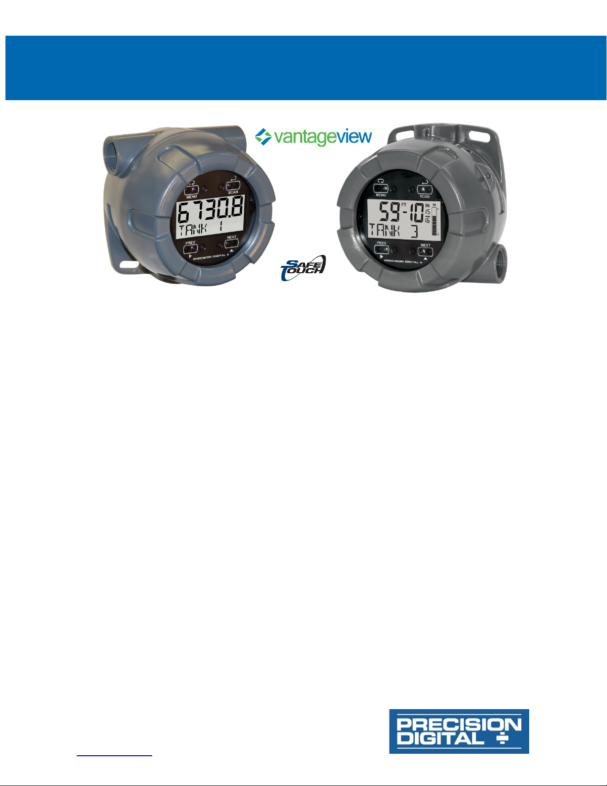
PD6730X Field-Mount Modbus® Scanners
PRECISION DIGITAL CORPORATION
www.predig.com
Instruction Manual
• NEMA 4X, IP66 Field-Mount Modbus Scanners
• Modbus Master, Slave, or Snooper Mode
• 0.4" (10.2 mm) 7 Alphanumeric Characters Lower Display for Process Variables, Custom Units, and Tags
• 5-Digit Decimal Display or Feet & Inches Display
• Display Mountable at 0°, 90°, 180°, & 270°
• SafeTouch Through-Window Button Programming
• Scan up to 16 Modbus Process Variables
• Independent Scaling, Tag, and Unit for Each PV
• Backlight Standard on All Models
• Isolated 4-20 mA Output Option
• Two Isolated Pulse Outputs Standard, up to 5 kHz
• Operating Temperature Range: -40 to 75°C (-40 to 167°F)
• Conformal Coated PCBs for Dust and Humidity Protection
• Password Protection
• Data Logging Functions and Modbus Accessible Data
• Free ScanView EX Programming Software
• On-Board Three-Wire Isolated RS-485 with Modbus RTU
• Wide Viewing Angle
• Flanges for Wall or Pipe Mounting
• Three 3/4" NPT Threaded Conduit Openings (Two Plugs Provided)
• 2" U-Bolt Kits Available
• Stainless Steel Tag Available
• 3-Year Warranty
233 South Street • Hopkinton MA 01748 USA
Tel (800) 343-1001 • Fax (508) 655-8990
Page 2
PD6730X Field-Mount Modbus Scanners
Disclaimer
The information contained in this document is
subject to change without notice. Precision
Digital Corporation makes no representations
or warranties with respect to the contents hereof;
and specifically disclaims any implied warranties
of merchantability or fitness for a particular
purpose.
• Read complete instructions prior to installation
and operation of the scanner.
• Risk of electric shock or personal injury.
• This product is not recommended for life support
applications or applications where malfunctioning
could result in personal injury or property loss.
Anyone using this product for such applications
does so at his/her own risk. Precision Digital
Corporation shall not be held liable for damages
resulting from such improper use.
• Failure to follow installation guidelines could
result in death or serious injury. Make sure only
qualified personnel perform the installation.
WARNING
Cancer and Reproductive Harm - www.P65Warnings.ca.gov
Limited Warranty
Precision Digital Corporation warrants this
product against defects in material or
workmanship for the specified period under
“Specifications” from the date of shipment from
the factory. Precision Digital’s liability under this
limited warranty shall not exceed the purchase
value, repair, or replacement of the defective unit.
See Warranty Information and Terms &
Conditions on www.predig.com
details.
© 2021 Precision Digital Corporation.
All rights reserved.
for complete
Instruction Manual
Introduction
The field-mount Vantageview Super Snoopers are
serial input RS-485 Modbus
Modbus devices are ideal for applications in need of
a rugged solution. The Vantageview decimal version
has a two-line decimal display. The Vantageview feet
& inches version’s top line displays level in feet and
inches up to 399 ft, 11 and 15/16 inches. It includes
a 20-segment tank level indicator.
Each can accept up to 16 Modbus process variables
(PVs), from up to 16 devices. The scanners
automatically cycle through the PVs, with the ability
to manually cycle PVs or pause scanning.
Up to four math channels (CV1-CV4) may be used to
perform math functions on any of the input variables.
Math functions include sum, difference, weighted
average, ratio and more. Nested math functions may
be used in these math equations, allowing for
complex math functions.
The display is programmable to show any input, math
channel, units, or tags, on a variety of display
combinations between the top and bottom displays.
Standard features include SafeTouch through-window
buttons for operating the scanner without removing
the cover, a backlight that makes the display mode
visible in any lighting condition, 511 points of input
data logging, and two open collector pulse or alarm
outputs. A 4-20 mA output is available as an option.
The enclosure has three threaded conduit holes, integrated pipe or wall mounting flanges, and allows for
easy installation of tamper seals. Two conduit plugs
are installed; additional plugs are available (part number PDAPLUG75P).
Free, PC-based, ScanView EX software that connects
to the scanner via the PDA8068, PDA7485-I, or the
PDA8485-I is available for programming and setup of
the instrument.
The instrument can also be programmed using the
four SafeTouch through-window buttons, without
removing the cover, or with four internal push-buttons.
The PD6730X includes on-board data logging of up to
511 points.
®
RTU scanners. These
2
Page 3

PD6730X Field-Mount Modbus Scanners
Ordering Information
Model Description
PD6730-AX0-I-2 Modbus RS-485 RTU scanner,
PD6730-AXA-I-2
PD6730-AX0-I-L
PD6730-AXA-I-L Modbus RS-485 RTU scanner,
Accessories
Model Description
PDAPLUG75P 3/4" Plastic Conduit/Stopping Plug
PDA0001 3/4" M-NPT to F-M20 Reducer
PDA0002 3/4" M-NPT to 1/2" F-NPT Reducer
PDA1024-01 24 VDC Power Supply for DIN Rail
PDA8068 USB Serial Adapter for Programming
PDA7485-I PDA7485 RS-232 to RS-485 Converter
PDA8485-I USB to RS-485 Isolated Converter
PDA6846
PDA6846-SS
PDA-SSTAG
9-30 VDC power.
Modbus RS-485 RTU scanner,
isolated 4-20 mA output,
9-30 VDC power.
Modbus RS-485 RTU scanner,
feet & inches display,
9-30 VDC power.
feet & inches display,
isolated 4-20 mA output,
9-30 VDC power.
Steel 2" U-Bolt Kit. All Material: Zinc
Plated Steel; (1) U-Bolt for 2" Pipe
with (2 each) Washers, Lock
Washers, and Nuts.
Stainless Steel 2" U-Bolt Kit. All
Material: Stainless Steel; (1) U-Bolt for
2" Pipe with (2 each) Washers, Lock
Washers, and Nuts.
Custom Stainless Steel Tag (see
website for convenient ordering form)
Instruction Manual
PDA1024-01 24 VDC Power Supply
The PDA1024-01 is a DIN rail mounted 1.5 A,
24 VDC power supply that can be used to power
the PD6730X.
PDA8068 USB Serial Adapter
The PDA8068 USB serial adapter is used to connect
the PD6730X directly to a computer via USB. It is
intended to be used for programming only. No live
monitoring is possible with this module.
PDA6846 2" U-Bolt Kits
The PDA6846 U-Bolt Kits provide a convenient way to
mount the PD6730X to 1.5" or 2" pipes. They are
available in steel and stainless steel
.
PDA-SSTAG Stainless Steel Tag
The PDA-SSTAG is a laser etched stainless steel tag
that can be customized with three lines of text. Each
tag comes with a stainless steel wire and lead seal for
easy mounting wherever you need.
3
Page 4

PD6730X Field-Mount Modbus Scanners
Table of Contents
Introduction ......................................................................................................... 2
Ordering Information .......................................................................................... 3
Specifications ..................................................................................................... 7
General ............................................................................................................ 7
Modbus Operating Modes ............................................................................. 8
Serial Communications ................................................................................. 8
Modbus Scanner Process Variables............................................................. 8
Math Channels ................................................................................................ 9
4-20 mA Transmitter Output .......................................................................... 9
Open Collector Outputs ................................................................................. 9
ScanView EX Programming Software ........................................................ 10
Safety Information ........................................................................................ 11
Tag and Tamper Seal Loop ......................................................................... 11
PDA-SSTAG Stainless Steel Tag .............................................................. 11
Installation......................................................................................................... 12
Unpacking ..................................................................................................... 12
Conduit Plugs ............................................................................................... 12
Mounting ....................................................................................................... 12
Dimensions ................................................................................................... 12
Connections ................................................................................................. 13
Wiring Diagrams ........................................................................................... 14
DC Power Connection ............................................................................... 14
4-20 mA Transmitter Output Connections .................................................. 14
RS-485 Signal Connections ....................................................................... 14
Open Collector Output Connections .......................................................... 14
Setup and Programming .................................................................................. 15
Overview ....................................................................................................... 15
ScanView EX Programming Software ........................................................ 15
SafeTouch Buttons ...................................................................................... 15
SafeTouch Button Tips and Troubleshooting ............................................. 16
Buttons and Display ..................................................................................... 17
Setting Numeric Values ............................................................................... 18
Setting Alphanumeric Labels (LABEL) ......................................................... 18
Main Menu ......................................................................................................... 19
Display Functions & Messages ................................................................... 19
Main Menu Programming ............................................................................ 21
Select Operating Mode (MODE) ..................................................................... 21
Master Mode (MASTER) .................................................................................. 22
PV Number Configuration (PV NUM) ........................................................... 22
Poll Time (T POLL) ..................................................................................... 23
Response Timeout (TIMEOUT) .................................................................... 23
Retries Before Error (RETRIES) .................................................................. 23
Slave Mode (SLAVE) ...................................................................................... 24
PV Number Configuration (PV NUM) ........................................................... 24
Slave Response Timeout (TIMEOUT) .......................................................... 24
Snooper Mode (SNOOPER) ............................................................................. 25
Snooper Mode Response Time (T RESP) .................................................. 25
Setup the Display (SETUP) ............................................................................ 26
Instruction Manual
4
Page 5

PD6730X Field-Mount Modbus Scanners
Setting Up the Display (DISPLAY) ................................................................ 26
Top Display (TOPDSP) ................................................................................. 27
Bottom Display (BOTDSP) ............................................................................ 27
PV Display Setup (PVSETUP) ...................................................................... 28
Math Channel Display Setup (MATH) .......................................................... 31
Tank Size Indicator (TANKSZ) ..................................................................... 33
Tag Display Time (T-TAG) .......................................................................... 33
Units Display Time (T-UNITS) .................................................................... 33
Scan Time (T-SCAN) ................................................................................... 33
Serial Communications Settings (COMM) ..................................................... 34
Scanner Modbus ID (SCAN ID) .................................................................. 34
Baud Rate (BAUD) ....................................................................................... 34
Transmit Delay Time (TXDELAY) ................................................................. 34
Parity (PARTIY)........................................................................................... 34
Advanced Menu ................................................................................................ 35
Display Functions & Messages ................................................................... 35
Advanced Menu Programming (ADVANCE) .................................................. 37
Open Collector Outputs (OUTPUT) .............................................................. 38
Scaling the 4-20 mA Analog Output (Aout) ................................................ 40
Selecting the Analog Output Source .......................................................... 40
Enter Display and Output Values ............................................................... 41
Math Channel (CV1 to CV4) Programming (MATH) ..................................... 41
Setting Up Passwords (PASSWRD) ............................................................... 43
Custom (CUSTOM) ....................................................................................... 44
System (SYSTEM) ........................................................................................ 45
Operation........................................................................................................... 49
Front Panel Buttons Operation ................................................................... 49
Pause/Start Automatic Scanning ................................................................ 50
Manual Scanning .......................................................................................... 50
Reset Scanner to Factory Defaults ............................................................. 50
Factory Defaults & User Settings................................................................ 51
Application Examples ...................................................................................... 55
Example 1: Master Polling Multivariable Level Transmitters ................... 55
Example 2: Snooper Displaying Flow Rate from Modbus Flowmeters ... 59
Troubleshooting ............................................................................................... 61
Troubleshooting Tips ................................................................................... 61
Quick User Interface Reference ...................................................................... 62
Instruction Manual
5
Page 6

PD6730X Field-Mount Modbus Scanners
Table of Figures
Figure 1. Enclosure Dimensions – Front View ................................................... 12
Figure 2. Enclosure Dimensions – Side Cross Section View ........................... 12
Figure 3. Connector Board Mounted in Base of Enclosure .............................. 13
Figure 4. Connectors & Switches on Rear of Display Module .......................... 13
Figure 5. DC Power Connections ........................................................................ 14
Figure 6. 4-20 mA Output Connections .............................................................. 14
Figure 7. RS-485 3-Wire Serial Connections ...................................................... 14
Figure 8. RS-485 5-Wire Serial Connections ...................................................... 14
Figure 9. Open Collector Output Connections ................................................... 14
Figure 10. Real Time Clock Display Example – Decimal Model ........................ 45
Figure 11. Real Time Clock Display Example – Feet & Inches Model .............. 45
Instruction Manual
6
Page 7

PD6730X Field-Mount Modbus Scanners
Display
Top
Five digits, (0-99999),
automatic lead zero blanking.
Bottom
Seven alphanumeric
automatic lead zero blanking.
Symbols
High alarm, low alarm,
mode/disable, password lock
Feet & Inches
Top
Feet & Inches,
or 1/8 fraction display
Bottom
Seven Characters,
14-segment, 7-digits
Tank
Indicator
20-segments, F (Full)
Alarm
Indication
High and low alarm
Backlight
White
Display
Top and Bottom Display*: Process
display used only for level Modbus process
variables or math channels.
Backlight
White; it can be disabled/enabled in the
automatically turned off below -20°C.
Alarm
Indication
Flashing display plus HI/LO indicators
Scan and
Ambient > -20°C: Modbus PV scan rate
minimum.
Underrange
Upper Display: Decimal display flashes
Lower Display: Flashes -
Overrrange
Upper Display: Decimal display flashes
Lower Display: Flashes
Programming
Four SafeTouch through-window buttons
Free ScanView EX software.
Password
Restricts modifications of programmed
password to make changes.
Input Power
9-30 VDC, 2.2 W
Data Logging
Up to 511 records, recorded 4/day at
log number.
Isolation
All Models:
500 V power-to-RS-485
serial communications
-AXA Models:
500 V power-to-analog
output
Environmental
Operating temperature range: -40 to 75°C
Printed circuit boards are conformally coated.
Non-Volatile
All programmed settings are stored in
years if power is lost.
Connections
Screw terminals accept 12 to 22 AWG
wire
Enclosure
NEMA 4X, IP66 plastic field enclosure,
Two ¾" NPT plastic conduit plugs included.
Tag or Tamper
Seal Loop
Loops molded into base and cover of
enclosure for tamper wire or tags.
Mounting
May be mounted directly to conduit. Two
mounting. See Dimensions on page 12.
Display
Orientation
Display may be mounted at 90° increments up to 270° from default orientation.
Overall
Dimensions
5.67" x 5.25" x 4.18" (W x H x D)
(144 mm x 133 mm x 106 mm)
Weight
1.65 lbs (26.4 oz, 0.75 kg)
Warranty
3 years parts and labor. See Warranty
www.predig.com for complete details.
Specifications
Except where noted all specifications apply to operation at +25°C.
General
Instruction Manual
settings to require re-entering the
Display
(-L Models)
Assignment
Display
Display
Display
Display
Level
Variables (PV); Alternating PV and Units,
Tag and PV, or Tag, PV, and Units.
Bottom Display: All Top Display Options
or Off
Units and tag independent for each PV.
* On feet and inches display models, top
0.7" (17.8 mm) high,
7- segment,
characters,
0.4" (10.2 mm) high,
14-segment,
SafeTouch button sleep
0.60" (15.2 mm) high,
FT
0 to 399
7-segment, programmable 1/16
0.4" (10.2 mm) high,
and E (Empty)
1115/16 IN
Memory
specific times or at defined time intervals.
Record contains first eight enabled Modbus PVs; C1-4 if enabled; date; time, and
Storage temperature range: -40 to 75°C
Backlight deactivated below
temperatures ≈ -20°C
Relative humidity: 0 to 90% non-condensing
non-volatile memory for a minimum of ten
polycarbonate with UV stabilizer.
Color: grey.
Window: Clear polycarbonate with UV
stabilizer.
Three ¾" NPT threaded conduit openings.
slotted flanges for wall mounting or NPS
1½" to 2½" or DN 40 to 65 mm pipe
Advanced - System menu. The backlight is
Update Rate
Method
programmable from 2 to 99 seconds per
PV. Tag and units programmable for 1 to 5
second alternation.
Ambient < -20°C: All Modbus scan, alternating units and tags 1 update/10 seconds
-9999
Level display flashes to 399FT 1115/16
99999
Level display flashes to 399FT 1115/16
when cover is installed. Four internal
pushbuttons when cover is removed.
Information and Terms & Conditions on
IN
999999
IN
999999
7
Page 8

PD6730X Field-Mount Modbus Scanners
Master
Processes and displays data read from
individually.
Slave
Processes data sent to it from a
https://www.predig.com for details.
Snooper
Listens to the Modbus traffic and picks up
returned value will be read.
Master Poll
Time
0.1 to 99.9 sec. Time between readcommands.
Master
0.1 to 99.9 seconds. Time elapsed after a
considers that request to have failed.
Number of
1-99. The number of retries the scanner
reporting an error condition on the PV.
Snooper
Time
0.1 to 99.9 seconds. Time since the last
error.
Slave Timeout
0.0 to 99.9 seconds. Time elapsed after
the last data received from a master before
the scanner considers the data to be out of
despite not being updated regularly.
Protocol
Modbus® RTU
Scanner Id
1 – 247. Specifies the address of the
PD6730X.
Baud Rate
1,200; 4,800; 9,600; 19,200; 38,400;
57,600; or 115,200 bps
Transmit Time
Delay
Parity/Stop Bit
with 2 stop bits
Byte-to-Byte
Timeout
Note: Refer to Modbus Register Tables at www.predig.com for details.
PV Inputs
Up to 16 independently programmed
disabled.
Slave Id
Specifies which device on the bus to
(Slave ID for PV1-16).
Register Number
Specifies which register(s) to read in
only.
Function Code
03, 04, and 65 (used to read 32 bit
only.
Data Type
Select the data format of the PVs.
point only.
Byte Order
Integer data programmable as binary
for short.
Modbus Operating Modes
Modbus RTU slave devices. Up to 16
process variables (PVs) from up to 16
slave devices. Each PV programmed
Modbus RTU master device.
Note: Refer to Modbus Register Tables at
a specific register or registers being polled
by a Master device from a specific slave
device and processes the data being read.
Up to 16 process variables (PVs) from up
to 16 devices.
If multiple registers are polled by the
master with one command, only the first
Timeout
Retries
Response
poll request is made before the scanner
will make when requesting data before
PV update the before being considered an
Instruction Manual
Modbus Scanner Process Variables
Modbus process variables (PVs) may
be scanned (Master mode) or detected
(Snooper mode). Each of the 16
Modbus PVs may be enabled or
monitor. Valid for Master and Snooper
modes only.
Assign the slave ID or address (1-247)
of each of the devices containing the
process variables to be displayed
the devices on the bus.
5 Digit Function 03: 40001–49999;
04: 30001–39999; or 65: 1–9999.
6 Digit Function 03: 400001–465535 or
04: 300001–365535; or 65: 1–65535.
Range is dependent on Function Code
selection (03, 04, or 65)
Will read 2 registers for Long integer
and Floating point data types; the
register entered and the next
consecutive register number.
Valid for Master and Snooper modes
Serial Communications
date. Programming 0 disables the timeout,
and PV data will be displayed indefinitely
Programmable between 0 and 199 ms
Even, odd, none with 1 stop bit, or none
Max of 1.5 character times or 750 μs
registers). Master & Snooper modes
Select between short integer (2 byte),
long integer (4 byte), or floating point
(4 byte). Slave mode uses floating
or BCD, and signed or unsigned. Byte
order selectable as big-endian (1234),
little-endian (4321), byte swap bigendian (2143), or byte swap littleendian (3412). Byte swap unavailable
8
Page 9

PD6730X Field-Mount Modbus Scanners
Math Result
Four math channels CV1-CV4.
programmed for a math function.
Math Functions
Parameter 1 (PAR1), parameter 2
math channel C1-C4.
Math Function
Function
Setting
Addition
PAR1 + PAR2
Difference
PAR1 - PAR2
Multiplication
PAR1 * PAR2
Division
PAR1 / PAR2
Absolute diff.
Abs(PAR1 - PAR2)
Weighted avg.
((PAR1 – PAR2)*PAR3) +PAR2
Draw
((PAR1 / PAR2) – 1) * PAR3
Ratio
(PAR1 / PAR2) * PAR3
Concentration
PAR1 / (PAR1 + PAR2) * PAR3
Constant
Constant
Long Integer
Constant
Floating Pt.
Constant
Absolute Value
Abs(PAR1)
Square Root
√(PAR1)
Parameter
Parameter 1 (PAR1), parameter 2
Parameter
Defining parameter 1 or 2 as a math
Output Source
Modbus PV 1-16, math channel 1-4, or
disabled
Scaling Range
4.000 to 20.000 mA for any display range.
Disable
If disabled, the output will output 3.2 mA
Calibration
Factory Calibrated:
0.0 to 1000.0 = 4-20 mA output
Underrange
Output Underrange: 3.8 mA
Overrange
Display Overrange: 20.5 mA
Output Overrange: 20.5 mA
Accuracy
± 0.05% span ± 0.004 mA
Temperature
Drift
0.08 µA/°C max from -40 to 75°C ambient
External Loop
Power Supply
30 VDC maximum
Output Loop
Power supply
Minimum
Maximum
24 VDC
10 Ω
750 Ω
30 VDC
100 Ω
1100 Ω
Note: loop-powered backlight subtracts 150 Ω from maximum resistance
figures above.
Output
Two open collector pulse outputs.
math channel, constant timed pulse output;
Out 2), or off.
Rating
Isolated open collector, sinking NPN,
30 VDC @ 150 mA max.
Alarm Output
Assign to Modbus PV 1-16 or math
point.
Alarm
Deadband
0-100% FS, user selectable
Alarm
Acknowledge
Front panel ACK button resets output and
screen indication.
Pulse Output
The pulse output count (
) is
Count value.
Pulse Output
Pulse Width
Unless otherwise stated, pulses are 50%
duty cycle for required frequency.
Pulse Output
Frequency
5 kHz, pulse width at 50% duty cycle.
will display
Quadrature
Output set to quadrature will lag the other
output frequency. Minimum 1 Hz
Timer Output
Programmable on and off time, repeating
maximum
second, maximum 10,000 seconds.
Math Channels
Instruction Manual
4-20 mA Transmitter Output
Chanels
None
Selection
Nested Math
Each math channel may be
(PAR2), and parameter 3 (PAR3)
independently programmable for each
SUM
DIF
MULTI
DIVIDE
DIFABS
WAVG
DRAW
RATIO
CONCEN
CONST
LONG
FLOAT
Disable
NONE
ABS
SQrt
(PAR2), and parameter 3 (PAR3)
selectable as: Modbus PV1-16, math
channel CV1-4 or any math function.
function will prompt for level 2
parameter 1 (L2P1), level 2 parameter
2 (L2P2), and/or level 2 parameter
3 (L2P3). Level 2 parameters function
identically as parameter 1 and 2 for
nested math functions.
Resistance
Open Collector Outputs
Assignment
Count
Individually programmable for Modbus PV,
quadrature outputs (requires Out 1 and
channel 1-4, for high or low alarm trip
COUNT
programmable from 0.000001 to 9999999.
PV and math channels generate a frequency
equal to the PV or math value divided by the
9
Maximum
Output
If the outputs exceed 5 kHz, the scanner
pUlse OVERRNG
pulse output by 90° (1/4 duty cycle) at
cycle. Minimum period 0.1 second,
100,000 seconds. Minimum pulse time 0.01
Page 10
PD6730X Field-Mount Modbus Scanners
System
Requirements
Windows® 7/8/10 (Windows 32-bit or
64-bit operating systems)
Communications
485 Isolated
Protocol
Modbus RTU
Scanner Address
1-247
Baud Rate
1200 bps to 115,200 bps
Configuration
Configure one scanner at a time.
Monitor file format: Saved as ".mcf".
Data Logging
Report
Saved as “.csv” file format.
ScanView EX Programming Software
PDA8068 Meter-to-USB Adapter for
programming,
PDA7485-I RS-232 to RSConverter (Cable not included),
PDA8485-I USB to RS-485 Isolated
Converter (Cable not included).
Instruction Manual
File format: Saved as “.mve".
Printing: Configuration can be printed.
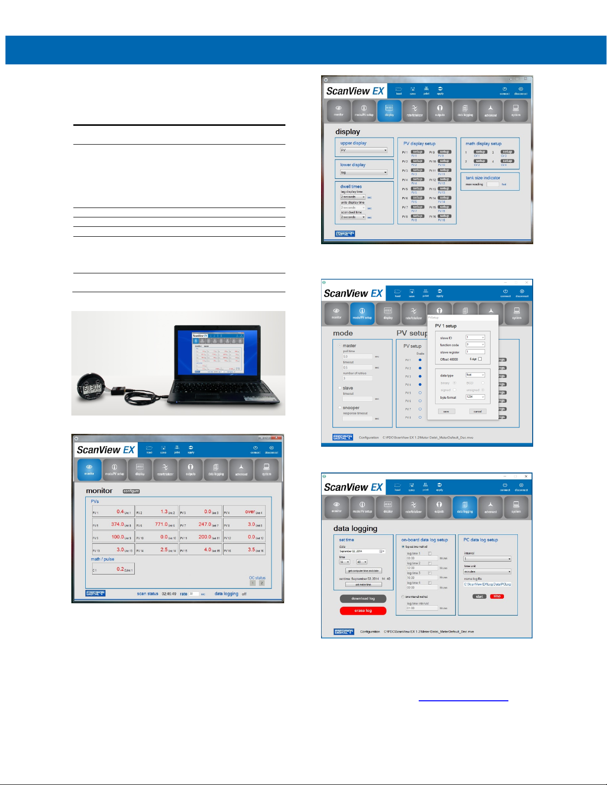
The Display window is used for programming the upper
display, lower display, dwell times, PV display setup, math
display setup, and tank size indicator.
The Mode/PV Setup window is used for selecting master,
slave, or snooper modes and setting up from 1-16 PVs.
The Monitor window is used for monitoring up to 16 process
variables; each is programmed individually to display information
in selected engineering units with custom tags.
The Data Logging window is used to set the computer and
meter time/date, set the on-board data log set time or time
interval method, set PC data log intervals and time units, and
manual control of PC data log with start/stop buttons.
For detailed programming software instructions or to download
ScanView EX software, visit predig.com/scanview-ex
10
.
Page 11
PD6730X Field-Mount Modbus Scanners
Safety Information
• Read complete instructions prior to installation and
operation of the scanner.
• Installation and service should be performed only
by trained service personnel. Service requiring
replacement of internal components must be
performed at the factory.
• If the scanner is installed in a high voltage
environment and a fault or installation error occurs,
high voltage may be present on any lead.
Tag and Tamper Seal Loop
Instruction Manual
PDA-SSTAG Stainless Steel Tag
The PDA-SSTAG is a laser etched stainless steel tag
that can be customized with three lines of text. Each
tag comes with a stainless steel wire and lead seal for
easy mounting wherever you need.
Dimensions
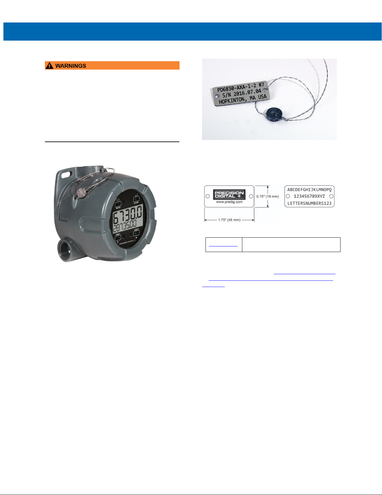
The PD6730X comes with tag and tamper seal loops
molded into the plastic enclosure. One loop is located
on the cover of the enclosure and the other one is on
the base of the enclosure. These are used for inserting
a stainless steel wire through the holes and attaching a
lead seal to prevent unauthorized removal of the
enclosure cover. A custom stainless steel tag (PDASSTAG) can also be attached to the wire.
Ordering Guide
PDA-SSTAG
When ordering custom tags, enter your custom text in
the available form located at predig.com/PDA-SSTAG
or click here to download the Stainless Steel Tag Or-
der Form
Custom Stainless Steel Tag
(see website for convenient ordering form)
11
Page 12
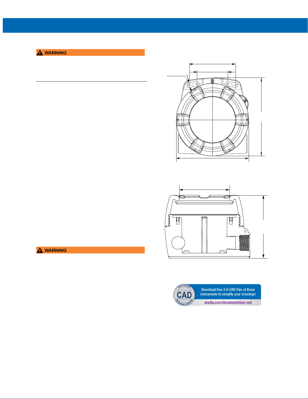
PD6730X Field-Mount Modbus Scanners
(85.1)
(57.2)
(144.0)
5.25
(133.3)
5.67
3.35
2.25
0.33
(8.3)
(106.1)
4.18
Ø
3.34
(84.9)
Instruction Manual
Installation
• Hazardous voltages may exist within enclosure.
• Installation and service should be performed only
by trained service personnel.
Wiring connectors are accessed by opening the
enclosure. To access electrical connectors, remove
the two captive screws, then disconnect the ribbon
cable from the display module and set the display
module aside.
Unpacking
Remove the scanner from box. Inspect the packaging
and contents for damage. Report damages, if any, to
the carrier.
If any part is missing or the scanner malfunctions,
please contact your supplier or the factory for
assistance.
Conduit Plugs
The PD6730X is supplied with two IP68 rated conduit
plugs for installations that require the use of only one
conduit entry. The conduit/stopping plugs have 1.29"
wrenching flats and a screwdriver slot.
Dimensions
All units: Inches (mm)
Figure 1. Enclosure Dimensions – Front View
Mounting
The PD6730X has two slotted mounting flanges that
may be used for pipe mounting or wall mounting.
Alternatively, the unit may be supported by the
conduit using the conduit holes provided.
Refer to Figure 1.
• Do not attempt to loosen or remove flange bolts
while the scanner is in service.
Figure 2. Enclosure Dimensions –
Side Cross Section View
12
Page 13
PD6730X Field-Mount Modbus Scanners
D+
P+
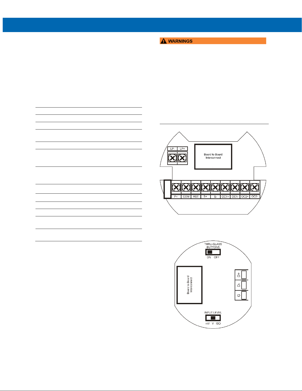
Connections
To access the connectors, remove the enclosure
cover and unscrew the two captive screws that fasten
the display module into the enclosure. Disconnect the
ribbon cable and remove the display module.
RS-485 serial connections are made to a removable
terminal block on the back of the display module.
Power and signal connections are made to a screw
terminal connector in the base of the enclosure.
RS-485 data B (non-inverting) connection
D- RS-485 data A (inverting) connection
G RS-485 shield ground connection
DC Power positive terminal connection
COM
RST Contact closure reset pull-up to 1.8 VDC
S+
S-
OC1+ Open collector output 1 positive terminal
DC power supply input return/negative,
reset contact closure common
Pulse input signal positive terminal
connection (Refer to LIM6730XPulse
for instructions).
Pulse input signal negative terminal
connection (Refer to LIM6730XPulse
for instructions).
Instruction Manual
• Observe all safety regulations. Electrical wiring
should be performed in accordance with all
agency requirements and applicable national,
state, and local codes to prevent damage to the
scanner and ensure personnel safety.
• Static electricity can damage sensitive
components.
• Observe safe handling precautions for
static-sensitive components.
• If the scanner is installed in a high voltage
environment and a fault or installation error
occurs, high voltage may be present on any lead
or terminal.
OC1- Open collector output 1 negative terminal
OC2+ Open collector output 2 positive terminal
OC2- Open collector output 2 negative terminal
LP+
LP-
Refer to Figure 3 and Figure 4 for terminal positions.
4-20 mA transmitter output DC power
positive terminal connection.
4-20 mA transmitter output DC power
negative terminal connection.
Figure 3. Connector Board Mounted in Base of
Enclosure
Figure 4. Connectors & Switches on Rear of Display
Module
13
Page 14
PD6730X Field-Mount Modbus Scanners
Power
Supply
COM
RST
P+
S+
S-
LP- LP+
Power
Supply
4-20 mA Input
Device
Vantageview
DO
DO
DI
DI
GND
RS-485 DEVICE
D+
DG
+
Alarm Indicator/
Pulse Counter
(e.g. PD6300)
-
5-30 VDC
150 mA MAX
P+
COM RST
S+
S-
OC1+
OC1-
OC2+
OC2-
LP+LP-
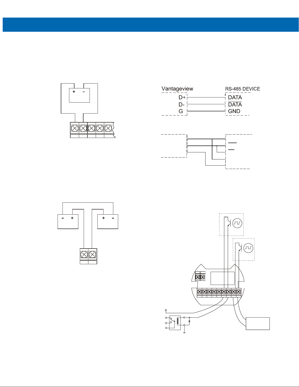
Wiring Diagrams
DC Power Connection
DC power is wired to terminals P+ and COM as shown
in Figure 5. To maintain input isolation, a separate
power supply must be used to power the isolated
4-20 mA transmitter as shown in Figure 6.
Figure 5. DC Power Connections
4-20 mA Transmitter Output Connections
Output connections are made to two terminals labeled
LP+ and LP-. Connect to an input device such as a remote display or chart recorder as shown in Figure 6.
Instruction Manual
RS-485 Signal Connections
The scanner includes a 3-wire RS-485 serial connection. The cabling used for an RS-485 serial communications network should always be a high quality cable
such as Belden 8162 or Alpha 6203C. A 3-wire system requires two twisted pairs (the extra twisted pair
is needed for the signal ground).
Figure 7. RS-485 3-Wire Serial Connections
Figure 8. RS-485 5-Wire Serial Connections
Open Collector Output Connections
Open collector output 1 and 2 connections are made to
terminals labeled OC1+ and OC1-, and OC2+ and
OC2-. Connect the alarm or pulse input device as
shown in Figure 9.
Figure 6. 4-20 mA Output Connections
Figure 9. Open Collector Output Connections
14
Page 15
PD6730X Field-Mount Modbus Scanners
front window is being unblocked.
Setup and Programming
Overview
Setup and programming is done through the infrared
through-window SafeTouch buttons, using the mechanical buttons when uncovered, or with ScanView
EX programming software. There are two slide
switches located on the display module. One switch is
used to lock or unlock the SafeTouch Buttons. The
other switch is used to configure the pulse input
(Refer to LIM6730XPulse for instructions).
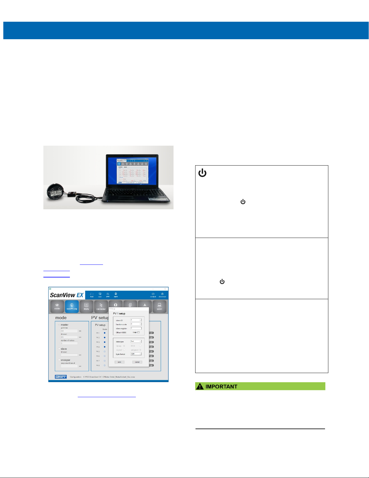
ScanView EX Programming Software
The fastest and easiest way to program the meter is
using the free ScanView EX programming software.
This software greatly simplifies the programming process and allows the user to save configuration files for
later use.
The ScanView EX software requires one of several
options to connect to a PC depending on the PC’s
hardware; The PDA8068
PDA7485-I RS-232 to RS-485 converter, or the
PDA8485-I USB to RS-485 Isolated Converter to
connect the PC to the meter.
USB serial adapter,
Instruction Manual
SafeTouch Buttons
The PD6730X is equipped with four sensors that
operate as through-window buttons so that it can be
programmed and operated without removing the
cover (and exposing the electronics). These buttons
can be disabled for security by using the THRUGLASS BUTTONS switch and selecting the OFF
setting. This switch is located on the back of the
removable electronics module.
SafeTouch Button Operation
To actuate a button, press and remove one finger
to the window directly over the marked button area.
Remove finger to at least 4 inches away from the
window in between button activations. SafeTouch
and mechanical buttons may be held to cycle through
menus or digits in place of repeatedly pushing a
button.
SafeTouch Power Save Mode
(Symbol shown on -2 decimal models only)
SafeTouch buttons enter a power saving mode after
three minutes of inactivity. This mode is indicated by
a power symbol ( ) appearing in the lower right of
the display. Only the MENU button is monitored in
this mode. To activate the SafeTouch buttons, press
and hold the menu button for up to five seconds.
The display will read AWAKE, and the SafeTouch
buttons will be fully enabled.
SafeTouch Disabled Mode
When the cover is removed, the four mechanical
buttons located next to the sensors may be used.
The sensors are disabled when a mechanical button
is pressed and will automatically be re-enabled after
60 seconds of inactivity. The SafeTouch power
symbol ( ) will blink in the lower right of the display
if the buttons are disabled due to a mechanical
pushbutton being pressed.
SafeTouch Button Equalize Delay
The SafeTouch buttons are designed to constantly
recalibrate for ambient conditions. When the cover
position is changed, the cover is removed, or an object is removed that was placed over the front window, it may take a moment for the SafeTouch buttons to recalibrate to the change in conditions.
Allow up to 2 minutes for the SafeTouch buttons
to recalibrate to new conditions in these cases
where the cover position was changed, or the
To download the ScanView EX programming
software, visit predig.com/scanview-ex
.
• SafeTouch will not work if two or more buttons
are detected as being pressed simultaneously.
Be careful to avoid triggering multiple buttons or
reaching across one button location to press
another.
15
Page 16

PD6730X Field-Mount Modbus Scanners
SafeTouch Button Tips and Troubleshooting
The SafeTouch Buttons are designed to filter normal
levels of ambient interference and to protect against
false triggering, however it is recommended that the
SafeTouch Buttons be turned off (slide THRU-GLASS
BUTTONS switch to OFF) if there is an infrared interference source in line-of-sight to the display or if the
buttons are not needed.
SafeTouch Button Tips:
• To the extent possible, install the display facing
away from sunlight, windows, reflective
objects, and any sources of infrared
interference.
• Keep the window clean.
• Tighten the cover securely.
• Use a password to prevent tampering.
• If the cover has not been installed and secured
tightly, it may take a moment for the SafeTouch
buttons to properly self-calibrate when the
cover is tightened.
After all connections have been completed and verified, connect the ribbon cable to the display module,
fasten the display module to the base, install enclosure cover, and then apply power.
Instruction Manual
SafeTouch Button Equalize Delay
The SafeTouch buttons are designed to constantly
recalibrate for ambient conditions. When the cover
position is changed, the cover is removed, or an
object is removed that was placed over the front
window, it may take a moment for the SafeTouch
buttons to recalibrate to the change in conditions.
Allow up to 2 minutes for the SafeTouch buttons to
recalibrate to new conditions in these cases where
the cover position was changed, or the front
window is being unblocked.
16
Page 17
PD6730X Field-Mount Modbus Scanners
HI
High Alarm
LO
Low Alarm
Settings Lockout Password
Enabled
SafeTouch Power Save/Dis-
Button
FT
Feet
IN
Inches and Fractional Inches
F
Tank Full Indicator
E
Tank Empty Indicator
HI
High Alarm
LO
Low Alarm
MENU
PREV
NEXT
SCAN
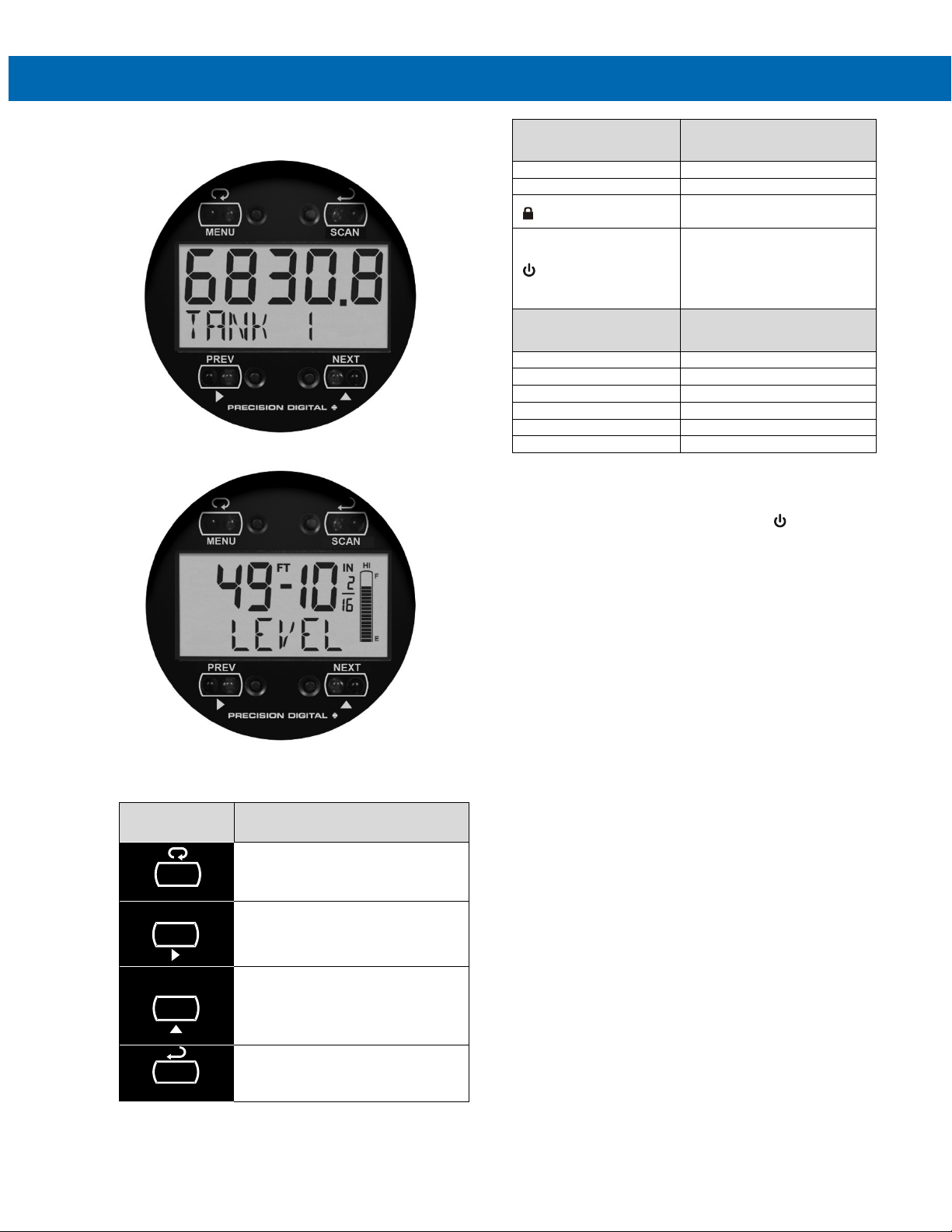
Buttons and Display
Decimal Display
Symbols (-2 Models)
Instruction Manual
Description
able
Flashing: Temporarily
Disabled Due to Mechanical
Decimal Display Model
Feet & Inches Display Model
Button
Symbol
Menu / SafeTouch Awake
Previous PV or Right Arrow
Up Arrow or Next PV
Enter or Start / Pause Scanning
Description
Feet & Inches Display
Symbols (-L Models)
Menu Button
• Hold the Menu SafeTouch button when in
power save mode (display will show ) to
awaken SafeTouch buttons.
• Press the Menu button to enter Programming
Mode.
• Press the Menu button during Programming
Mode to return to the previous menu
selections.
• Hold the Menu button for 1.5 seconds at any
time to exit Programming Mode and return to
Run Mode.
• Press and hold the Menu button for 3 seconds
to access the Advanced Features of the
scanner.
Right / Previous Button
• Press Previous to manually display the
previous PV or input display.
• Press the Right arrow button in programming
mode to move to the next digit or decimal
position.
• Press the Right arrow button in programming
mode to go backward through most selection
menus.
Up / Next Button
• Press Next to manually display the next PV or
input display.
• Press the Up arrow button in programming
mode to scroll forward through the menus,
decimal point, or to increment the value of a
digit.
Enter / Scan Button
• Press Scan to pause automatic scanning.
• Press Scan to resume automatic scanning
when paused.
• Press the Enter button in programming mode
to access a menu or to accept a setting.
Description
17
Page 18
PD6730X Field-Mount Modbus Scanners
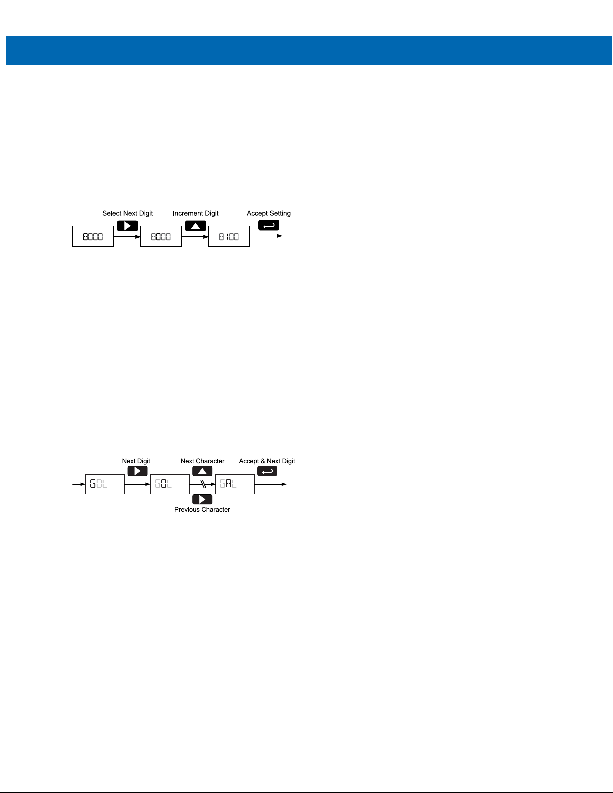
Setting Numeric Values
Instruction Manual
The numeric values are set using the Right and Up
arrow buttons. Press Right arrow to select next digit
and Up arrow to increment digit.
The digit being changed blinks.
Press the Enter button, at any time, to accept a setting or Menu button to exit without saving changes.
The decimal point is set using the Right or Up arrow
button in the Setup, Decimal Point menu.
Setting Alphanumeric Labels
LABEL)
(
Fully alphanumeric values are set using the Right
button to select the digit, the Up and Right arrow buttons to select the digit reading, and the Enter button
to confirm and select the next digit.
Menus using this entering method include tags and
custom units. After selecting the digit, and using the
Up and Right arrows to modify the digit, the display
will read CHAR.
Press Enter to confirm the new digit and proceed to
the next digit.
The digit being changed blinks.
Press the Menu button to exit without saving changes.
18
Page 19

PD6730X Field-Mount Modbus Scanners
Display
Parameter
Action/Setting
PV
UNSIGND
Main Menu
Display Functions & Messages
The scanner displays various functions and messages during setup, programming, and operation. The
following table shows the main menu MODE, SETUP,
and COMM menu functions and messages in the order
they appear in the menu. Functions and messages
that appear in the Advanced menu can be found in
the Advanced Menu section on page 35.
MODE
MASTER
PV NUM
PV 1
ENABLE
SLAVEID
FUNCODE
REG NUM
DATATYP
FLOAT
SHORT
LONG
BINARY
BCD
SIGNED
BYTE
1234
4321
2143
3412
DISABLE
T POLL
Mode Enter Mode menu
Master Mode Select Master mode
PV Number Enter the Modbus PV
PV 1 – PV 16 Enter PV1 to PV16
Enable Enable the Modbus
Slave ID Enter the slave
Function Code
Register
Number
Data Type Set the data type
Float Float data type
Short Short integer data
Long Long integer data
Binary Binary integer type
BCD
Unsigned Unsigned integer
Signed Signed integer type
Byte Select the byte
1243 Big endian
4321 Little endian
2143
3412
Disable Disable the Modbus
Poll Time
configuration menu
configuration menus
Modbus ID
Set the Modbus
function code
Enter the slave
register number
type
type
Binary coded
decimal integer type
type
format
Big endian with byte
swap
Little endian with
byte swap
PV
Set the Modbus PV
poll time
Instruction Manual
Display Parameter Action/Setting
TIMEOUT
RETRIES
SLAVE
PV NUM
PV 1
ENABLE
DISABLE
TIMEOUT
SNOOPER
PV NUM
T RESP
SETUP
DISPLAY
TOPDSP
PV
PV-U
TAG-PV
TG-PV-U
BOTDSP
TAG
TAG-U
UNITS
PV
TG-PV-U
OFF
PVSETUP
PV-1
FORMAT
Response
Timeout
Retries Set number of retires
Slave Select Slave mode
PV Number Enter the Modbus PV
PV 1 – PV 16 Enter PV1 to PV16
Enable
Disable
Response
Timeout
Snooper Mode Select Snooper
PV Number Enter the Modbus PV
Response Time Set Modbus
Setup Menu Enter Setup menu
Display Enter the Display
Top Display Set the function of
PV Display Modbus PV
PV & Units
Tag & PV Display tag and
Tag, PV, & Units Display tag, Modbus
Bottom Display Set the function of
Tag Display tags
Tag & Units Display tags and
Units Display units
PV Display Modbus PV
Tag, PV, & Units Display tag, Modbus
Off Turn off display
PV Setup
PV-1 to PV-16 Select PV1 to PV16
Format Enter PV display
Set Modbus
communication
response timeout
before display a PV
communication error
configuration menu
configuration menus
Enable the Modbus
PV
Disable the Modbus
PV
Set Modbus
response error time
mode
configuration menu
response error time
menu
the top display
Display Modbus PV
and units
Modbus PV
PV, and units
the bottom display
units
PV, and units
Enter the PV Setup
menu
format
19
Page 20

PD6730X Field-Mount Modbus Scanners
Display Parameter Action/Setting
TAG
UNITS
DISP.DP
FLOAT.DP
SCALE
FACTOR
LINEAR
MP-SCAL
MATH
CV 1
FORMAT
TAG
UNITS
Disp.DP
TANKSZ
T-TAG
T-UNITS
T-SCAN
PULSE.IN
COMM
SCAN ID
BAUD
TXDELAY
Tag Enter to edit PV tag
Units Enter to edit PV units
Display Decimal
Point
Float Decimal
Point
Scale Select the PV display
Conversion
factor
Linear Linear scaling
Multipoint
Scaling
Math
CV1 to CV4 Select math channel
Format Enter CV display
Tag Enter the CV tag
Units Enter the CV units
Display Decimal
Point
Tank Size Enter tank level
Tag Time
Units Time Enter unit display
Scan Time Enter scan cycle time
Input Refer to pulse input
Communications Enter the
Scanner ID Enter the scanner’s
Baud Rate Select baud rate
Transmit Delay Enter the transmit
Set the PV display
decimal point
Note: Not available
on Ft-In models.
Set the float decimal
point location (if PV
is float data type
only)
Note: Not available
on Ft-In models.
scaling: factor, linear
2-point, or multi-point
Conversion factor
scaling
Multipoint scaling for
PV1
Enter Math menu
(Will only appear if at
least one math
channel is enabled)
to configure CV 1 to
CV4
format
Set the CV display
decimal point
indicator full value
(in feet for Ft & In
version only)
Enter tag display
time
time
(e.g. PV dwell time)
manual
Communications
menu
Modbus ID (used if
setup as a slave)
delay
Instruction Manual
Display Parameter Action/Setting
PARITY
EVEN
ODD
NONE 1
NONE2
Parity Select parity mode
Even Even parity
Odd Odd parity
None, 1 Stop Bit No parity, 1 stop bit
None, 2 Stop
Bits
No parity, 2 stop bits
20
Page 21
PD6730X Field-Mount Modbus Scanners
Main Menu Programming
Instruction Manual
Select Operating Mode (MODE)
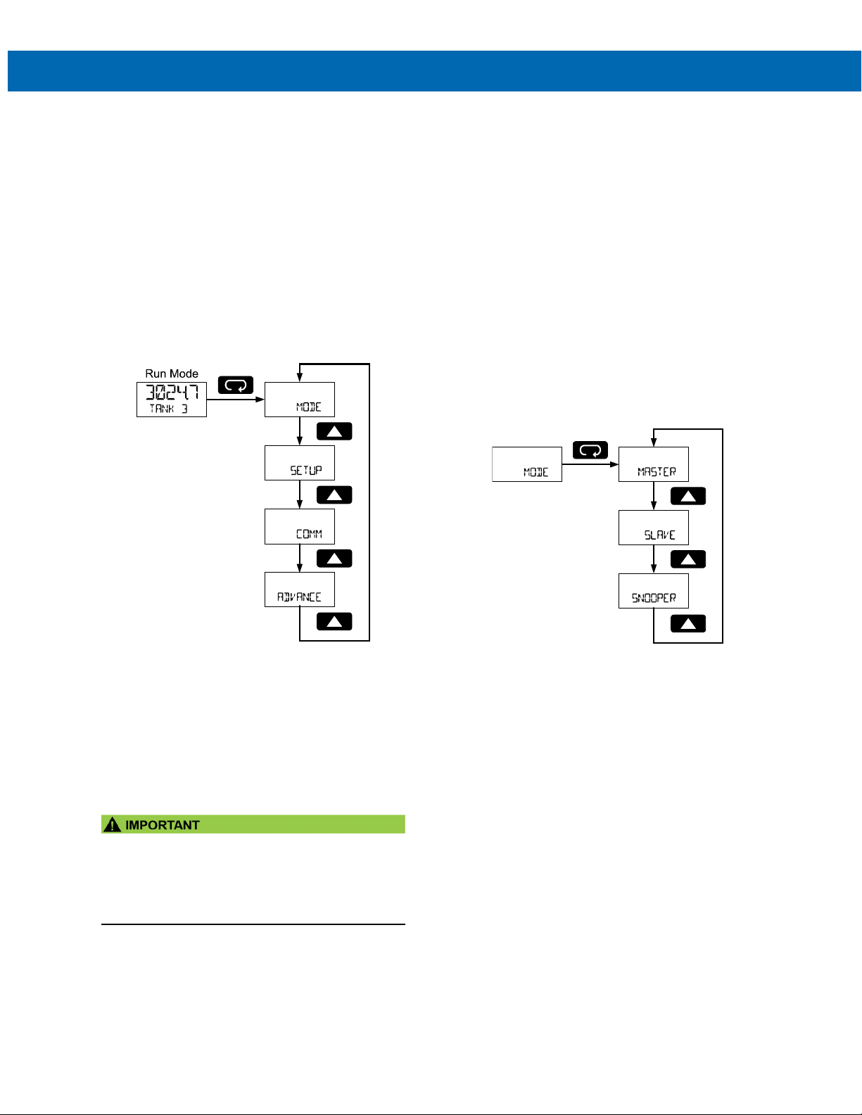
The main menu is used to navigate the programming
menus and separates the most commonly used
functions. The Mode menu is used to setup the
scanner as a Modbus master, slave, or snooper, and
define Modbus PVs. The Setup menu is used to setup
general scanner parameters, such as display
assignments. The Comm menu configures the
RS-485 serial communications settings. The
Advanced menu is used to configure more complex
settings not used with most common applications.
Press Menu button to enter Programming Mode then
press the Up arrow button to scroll through the main
menu.
The Mode menu is used to select master, slave, or
snooper operating mode. Only one of these modes
may be used. The programming of each mode is detailed below.
Master mode is used to configure the scanner as a
Modbus master. It will poll up to 16 registers in up to
16 Modbus slave devices. Slave mode is used to configure the scanner as a Modbus slave. A Modbus
master must be used to send data to the Modbus registers of the scanner for display. Snooper mode is
used to listen for data polled by a Modbus master on
the Modbus network. The scanner will detect up to 16
Modbus registers polled by the master.
Press the Enter button to access any menu or press
the Up arrow button to scroll through choices.
Press the Menu button to back out of a menu or hold
the Menu button to exit at any time.
Press Menu, at any time, to return to the previous
menu selection. Press and hold the Menu button for
1.5 seconds at any time to return to Run Mode.
Changes to the settings are saved to memory only
after pressing Enter.
The display moves to the next menu every time a
setting is accepted by pressing Enter.
• The Advanced menu contains parameters not
required for all applications. The setup of features
and functions detailed in the Advanced features
menu are found in the Advanced Menu
Programming (ADVANCE) section on page 37.
21
Page 22
PD6730X Field-Mount Modbus Scanners
Master Mode (MASTER)
In Master mode, the scanner will poll up to 16 Modbus
registers in up to 16 Modbus devices. It will serve as a
Modbus network master; polling Modbus slave devices for Modbus process variables (PVs) that can be
displayed or used in the math functions.
Programming the Modbus Master mode will include
defining the Modbus PV registers and devices, selecting the polling time interval, and the maximum response time allowed.
Instruction Manual
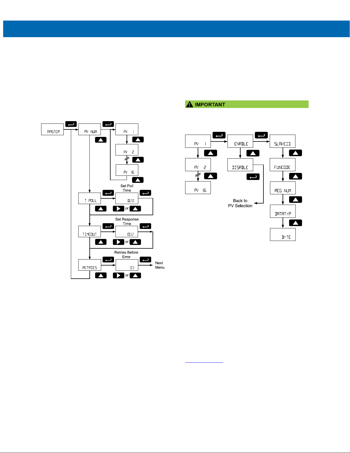
PV Number Configuration (PV NUM)
The PV Number menu is used to enable and disable
each Modbus PV 1 to PV 16. The Modbus device and
registers are configured for each of the enabled PVs.
PVs that are not enabled will not appear in other programming menus for display or inclusion in math
channel functions (CV).
PV1 to PV16 are programmed using identical menus.
• To enable a PV it must be assigned to a specific
slave ID.
Enable/Disable PV (ENABLE, DISABLE)
Enable or disable the Modbus PV. Disabled PVs will
require no additional configuration. Disabled PVs will
not be accessible in other menus or functions.
Slave ID (SLAVEID)
Enter the Modbus ID of the slave device that contains
the PV information.
Function Code (FUNCODE)
Select the Modbus function code necessary to read
the device. Use the Up and Down arrows to select
the appropriate function code, and press Enter to ac-
cept the function code.
See the PD6730X Modbus Register Table available at
www.predig.com
codes.
for more information on function
22
Page 23
PD6730X Field-Mount Modbus Scanners
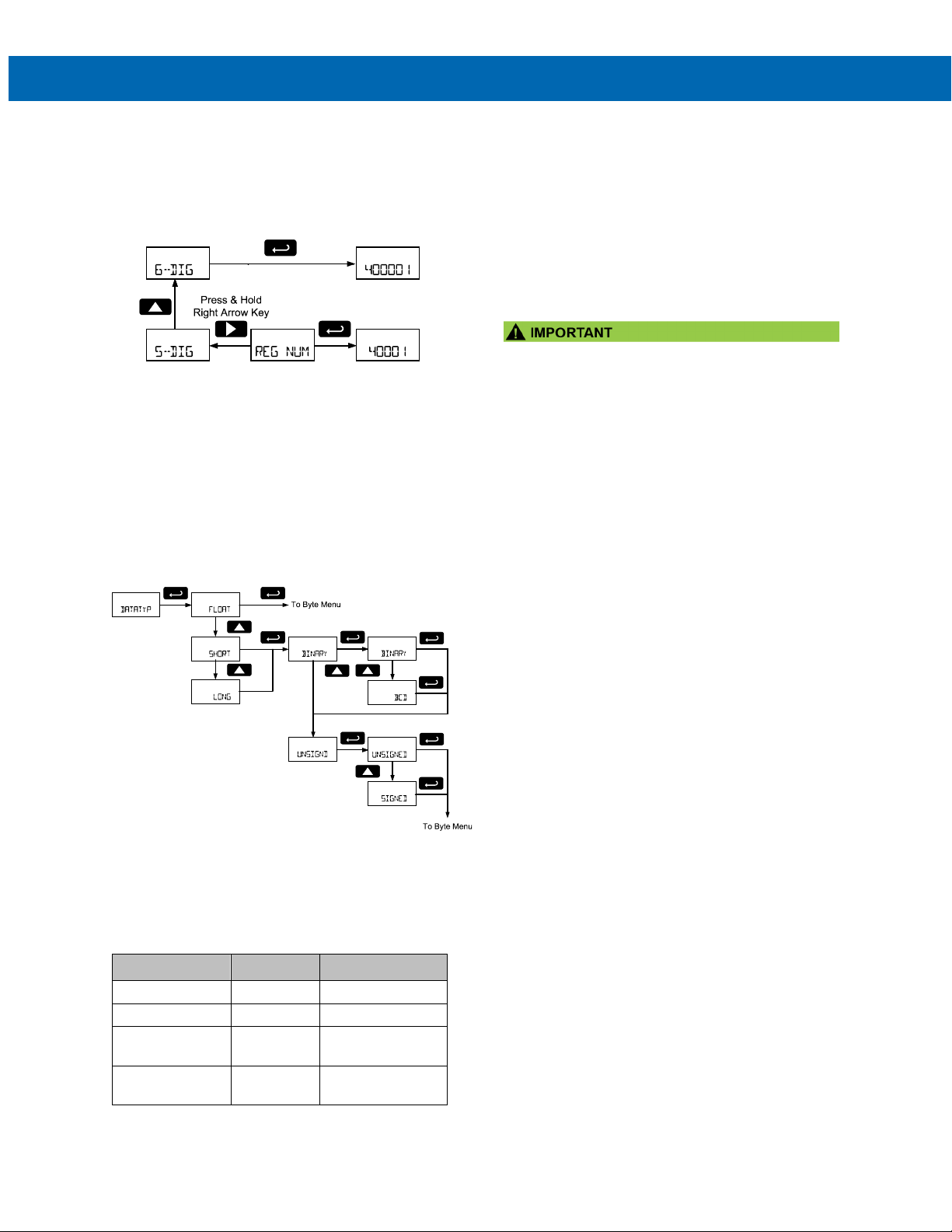
Register Number (ReG NUM)
Enter the Modbus register number of the PV information on the Modbus slave device defined in the
Slave ID parameter.
Select 5-Digit or 6-Digit Register Number
Data Type (DATATYP)
Enter the data type of the PV information in the Modbus register. Selectable data types are float, short integer, and long integer.
Use the Up and Down arrows to select the appropriate data type and press Enter to accept.
For short and long integer types, select binary or binary coded decimal (BCD) formats as well as signed
or unsigned data format.
Byte Format (BYTE)
Select the PV data byte format as it is stored in the
Modbus slave device data register. Use the Up and
Down arrows to select the appropriate data type related to endianness and byte order.
Byte Selection Byte Type Description
1234
4321
2143 2143
3412 3412
1234 Big endian
4321 Little endian
Big endian with
byte swap
Little endian with
byte swap
Instruction Manual
Poll Time (T POLL)
Enter the time between read command sequences. In
other words, how often the display values are updated
in Master mode. The poll time defines how often the
device will begin scanning all enabled Modbus PVs.
For example, if the Poll Time is two seconds, the
scanner will begin polling all Modbus PVs every two
seconds.
This parameter defines the approximate time between
updates of a PV value. Communications errors may
make updating a PV take longer.
Note: Depending on the Response Timeout, and the
number of PV poll requests that time out, it may take
more than one poll time to poll all enabled Modbus
PVs. In this scenario, the scanner will begin another
round of polling at the next poll time interval.
For example: Due to transmission errors, the scanner
with a 2 second poll time requires 2.5 seconds to update all the Modbus PVs. It will begin the second polling of all the Modbus PVs at 4 seconds.
Note: In the feet and inches display models enter this
value in the format XX.X seconds, but no decimal
point is present in the display. For example: enter 20
for a poll time of 2.0 seconds.
Response Timeout (TIMEOUT)
Enter the time the scanner will wait after a request for
information has been sent to a slave device before it
will assume an error on that request. Increasing the
timeout will help eliminate polling errors when polling
slow devices. Increasing the response timeout will
also slow the PV update rate in systems that are experiencing communications failures.
Note: The feet and inches display models enter this
value in the format XX.X seconds, but no decimal
point is present in the display. For example: enter 20
for a poll time of 2.0 seconds.
Retries Before Error (RETRIES)
Enter the number of consecutive failures to poll a device that will result in a communications error message on the display. This is the number of times a
specific PV must be polled before the display indicates a communication failure rather than displaying
the available PV data. Increasing this number will allow for more polling failures before a communication
error is detected, which may be required for some unreliable networks. Increasing this number will also increase how long old data is displayed before a communication error is indicated.
23
Page 24
PD6730X Field-Mount Modbus Scanners
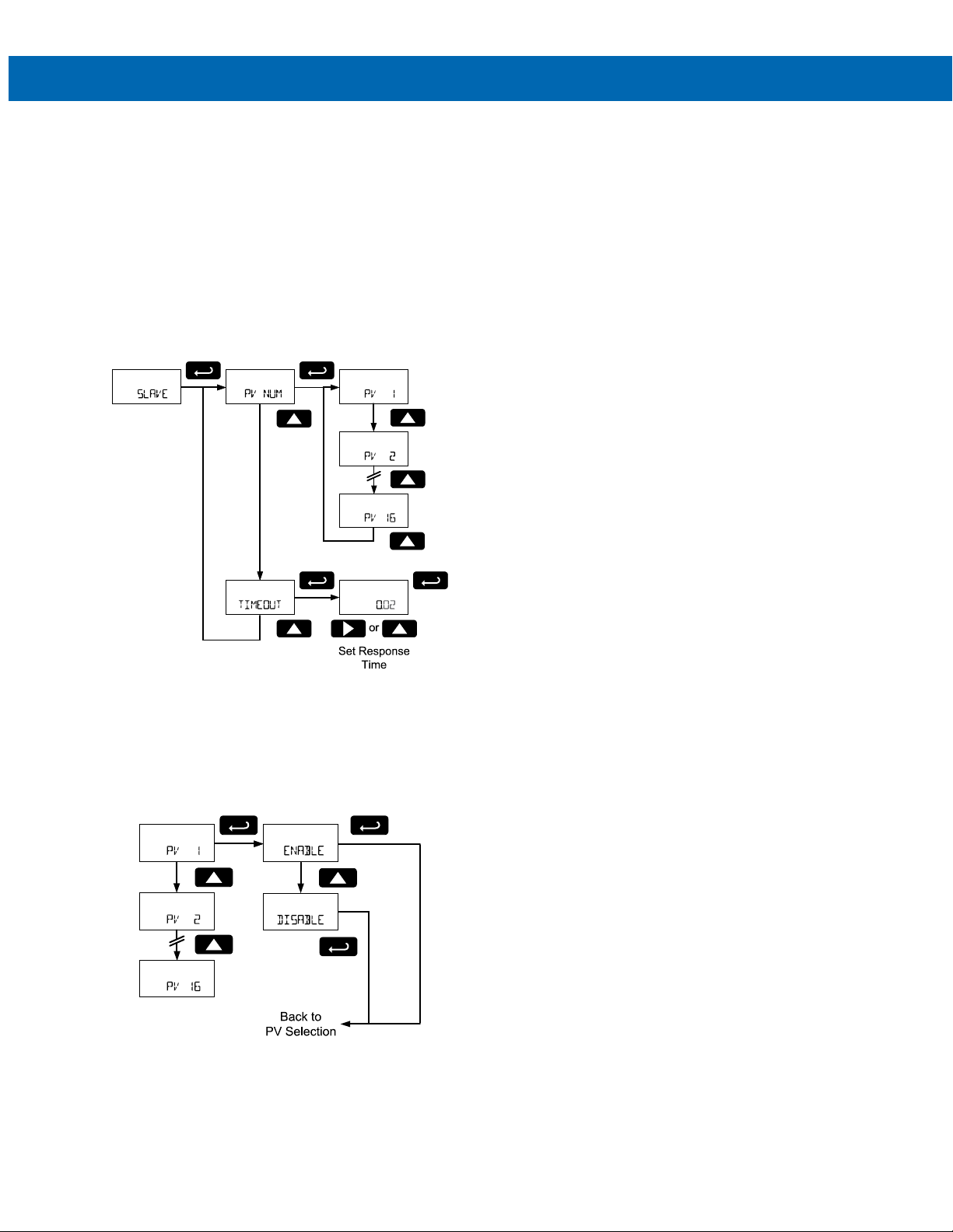
Slave Mode (SLAVE)
In Slave mode, a Modbus master may write up to 16
Modbus PVs to the scanner, which can then display
and process the data in the PV Modbus registers,
such as displaying the data and using them in math
functions.
Programming the scanner for Modbus Slave mode
will include defining the Modbus PV registers that are
enabled, as well as selecting the time between data
writes before an error is assumed. In Slave mode the
scanner accepts floating point data (Byte order: 1234
big endian).
Instruction Manual
Enable/Disable PV (ENABLE, DISABLE)
Enable or disable the Modbus PV. Disabled PVs will
require no additional configuration. Disabled PVs will
not be accessible in other menus or functions.
The Slave mode accepts floating point data type (Byte
order: 1234 big endian).
Slave Response Timeout (TIMEOUT)
If the Modbus data registers for the enabled Modbus
PVs are not updated within a certain period of time,
the scanner can presume that there is an error with
the data, or that it is too out of date to be worth displaying. In this case, the scanner will display this PV
as NONE (NONE).
At the Response Timeout menu, enter the time limit
for the scanner to continue to display data written to
the Modbus PV register. To disable this feature, and
always display the last data written to the Modbus
register regardless of how long ago the data was
updated, set this value to 0 seconds.
PV Number Configuration (PV NUM)
The PV Number menu is used to enable and disable
each Modbus PV 1 to 16. PVs that are not enabled
will not appear in other programming menus for
display or inclusion in math channel functions (CV).
PV1 to PV16 are programmed in identical menus.
24
Page 25
PD6730X Field-Mount Modbus Scanners
Snooper Mode (SNOOPER)
In Snooper mode, the scanner will act as a Modbus
network packet sniffer. The Snooper mode is used to
listen to data being transmitted on the bus. Up to 16
process variables may be read from the RS-485 bus
and displayed or used in math functions. The same
process variables can be displayed in multiple locations.
Instruction Manual
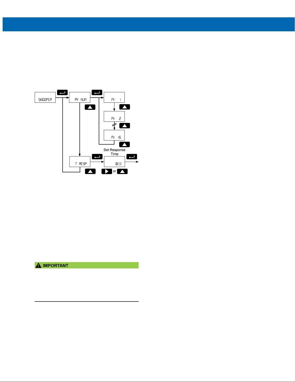
Snooper Mode PV Configuration
(PV NUM)
The PV Number menu is used to enable and disable
each Modbus PV 1 to PV 16. This menu is identical in
Master mode. Refer to PV Number Configuration (PV
NUM) on page 22.
Snooper Mode Response Time (T RESP)
If the Modbus data registers for the enabled Modbus
PVs are not updated within a certain period of time,
the scanner can presume that there is an error with
the data. After this time has passed, and updated
data has not been detected on the Modbus network,
the scanner will display this PV as NONE (NONE).
At the Response Time menu, enter the time limit the
scanner will display the Modbus PV register last data
monitored before it assumes an error.
Notes:
The poll time for scanners set up for Snooper mode
must be greater than the Master’s poll time. This
setting corresponds to the time window during which
the Snooper listens to the bus for a reply by the slave
device being polled by the master device. As soon as
the Snooper detects a new reply on the bus, the
display is updated. If there is no reply within the
Response Time setting, the Snooper goes into
communications break condition.
To minimize the possibility of communication errors
and communication break conditions, use a poll time
of 5 seconds or more with slow baud rates (e.g. 4800
bps or less).
• If multiple registers are polled by the master with
one command, only the first returned value will
be read.
• To snoop multiple PVs, the master must request
one PV at a time.
25
Page 26
PD6730X Field-Mount Modbus Scanners
Refer to manual
with pulse input
Note 4
Note 4
Note 3
Note 1
Note 2
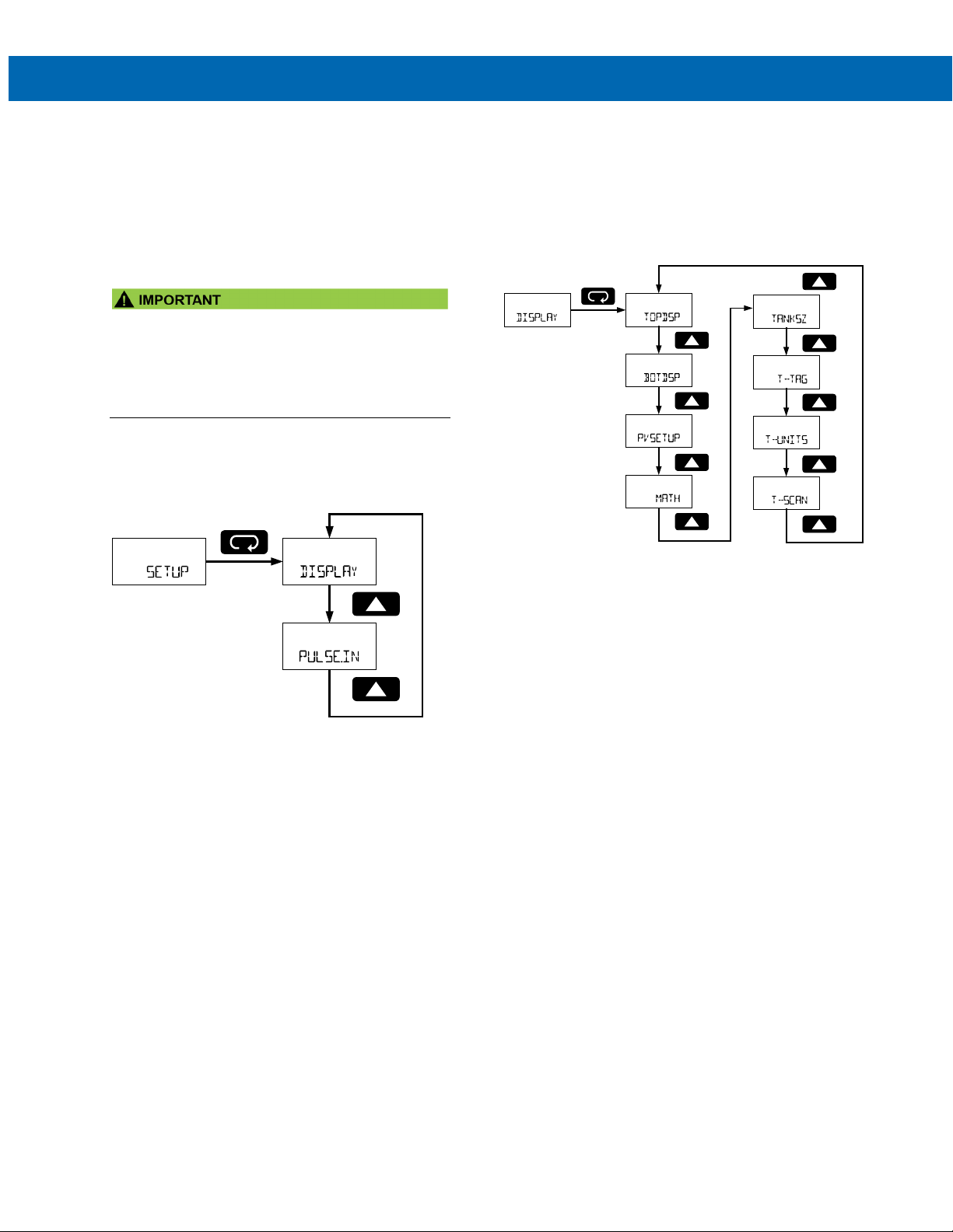
Setup the Display (SETUP)
Instruction Manual
Setting Up the Display (DISPLAY)
The Setup menu is used to select what information
will be displayed on the top and bottom display.
The Display menu is used to select the top and bottom display to show Modbus PVs and math channels,
and combinations of units and tags. The math channels are configured in the Advanced Features menu.
• The Pulse Input menu is not described or used in
this manual.
• For instructions on how to use and configure the
pulse input, refer to the LIM6730XPulse manual.
Press the Enter button to access any menu or press
the Up arrow button to scroll through choices.
Press the Menu button to back out of a menu or hold
the Menu button to exit at any time.
The Display menu is used to set parameters to show
on the top and bottom displays; select which PVs will
appear on the top and bottom displays; set how long
to display the tags and units; and program the scan
time for each channel (how long a specific channel
will display before moving to the next value).
Note 1: The Top Display menu does not appear on
feet and inches display models.
Note 2: The math menu (MATH) is only visible if a
math channel has been enabled. See Math
Channel (CV1 to CV4) Programming (MATH)
on page 41 for details about enabling the
math channels.
Note 3: The Tank Size menu appear only in Feet and
Inches Display Models.
Note 4: The Tag Time and Units Time menus will not
appear unless the Top Display or Bottom Display parameters are set to display or alternate
a tag or unit.
26
Page 27
PD6730X Field-Mount Modbus Scanners
Tag
Display tag
Tag and
Units
Display alternating
tag and units
Units
Display units
Display Modbus
PVs
Display alternating
and units
Display is turned
operation
Units
Display units
Tag
Display tag
Tag and
Units
Display alternating
tag and units
Display is turned
operation
Tag
Display tag
Display Modbus
PVs
Display alternating
PVs
Display alternating
and units
Display is turned
operation
TAG-PV
Units
Display units
Display Modbus
PVs
Display alternating
PVs
Display alternating
and units
Display is turned
operation
Display Modbus
PVs
Display alternating
PVs
Display alternating
and units
Display is turned
operation
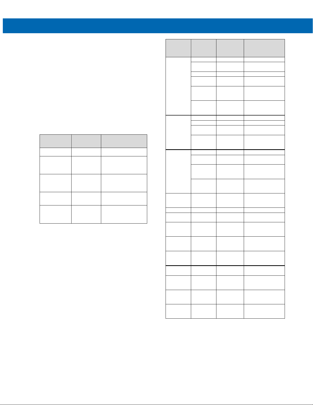
Top Display (TOPDSP)
Note: The Top Display menu does not appear on feet
and inches display models.
The Top Display menu sets what Modbus PV
information will be displayed on the top display. A
combination of Modbus PVs, tags, and units can be
selected to appear individually or as an alternating
display.
See PV Setup menu for details on selecting what
Modbus PVs appear on the top and bottom display.
Press Enter to access the Top Display menu and Up
button to scroll through choices. Press Enter to make
a selection and proceed to the next menu.
Press the Menu button to back out of a menu or hold
the Menu button to exit at any time.
Top Display
Selection
PV
PV-U PV and Units
TAG-U
TAG-PV Tag and PV
TG-PV-U
Parameter Description
PV Display Modbus PVs
Display alternating
Modbus PVs and
units
Tag and
Units
Tag, PV, and
Units
Display alternating
tags and units for bottom Modbus PVs
Display alternating tag
and Modbus PVs
Display alternating
tag, Modbus PVs, and
units
Top
Display
Selection
Feet &
Inches
Display
Models
PV
PV-U
OFF Off
PV PV
Bottom
Display
Selection
TAG
TAG-U
UNITS
PV PV
TG-PV-U
OFF Off
UNITS
TAG
TAG-U
OFF Off
TAG
PV PV
TAG-PV Tag and PV
TG-PV-U
UNITS
Parameter Description
Tag, PV,
and Units
Tag, PV,
and Units
Instruction Manual
tag, Modbus PVs,
off during normal
off during normal
tag and Modbus
tag, Modbus PVs,
off during normal
Note: Some top display selections may not appear if
no PV is assigned to display on the top display.
Bottom Display (BOTDSP)
The Bottom Display menu sets what Modbus PV
information will be displayed on the bottom display.
The available programming options for the bottom
display are determined by the Top Display menu
setting. For Ft & In level display models, the
selections for the Top Display menu are fixed. A
combination of Modbus PVs, tags, and units can be
selected to appear individually or as an alternating
display.
A selection without a PV component will use the
bottom display to show the unit or tag of the PV
displayed on the top display. These will change as
the top display PVs are scanned.
See PV Setup menu for details on selecting what
Modbus PVs appear on the top and bottom display.
Press Enter to access the Bottom Display menu and
Up button to scroll through choices. Press Enter to
make a selection and proceed to the next menu.
Press the Menu button to back out of a menu or hold
the Menu button to exit at any time.
TAG-PV Tag and PV
TG-PV-U
OFF Off
TG-PV-U PV PV
TAG-PV Tag and PV
TG-PV-U
OFF Off
Tag, PV,
and Units
Tag, PV,
and Units
tag and Modbus
tag, Modbus PVs,
off during normal
tag and Modbus
tag, Modbus PVs,
off during normal
Note: Some top display selections may not appear if
no PV is assigned to display on the top display.
27
Page 28
PD6730X Field-Mount Modbus Scanners
No
te 2
Note 1
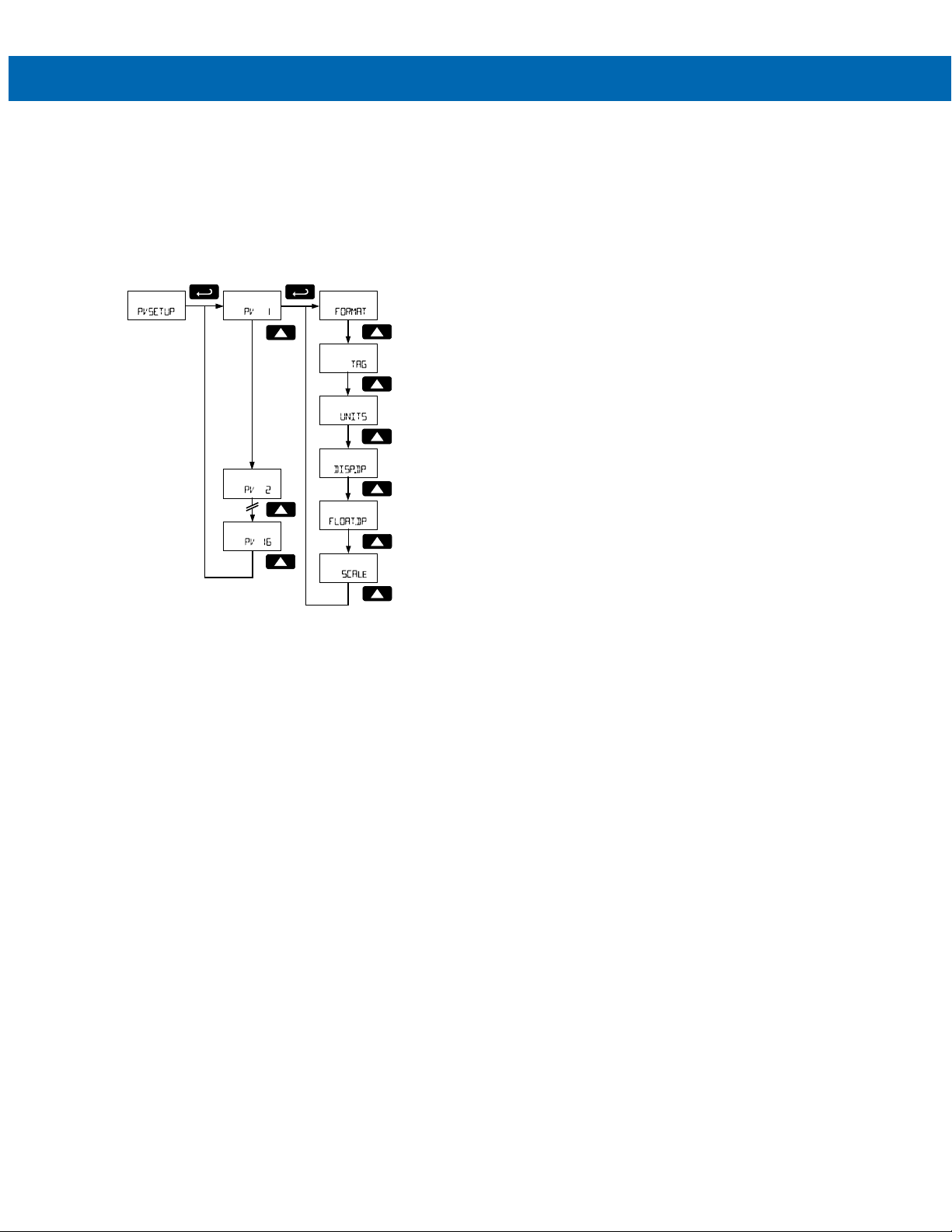
PV Display Setup (PVSETUP)
The PV Display Setup menu is used to configure the
display options for each Modbus PV setup in the PV
Number Configuration (PV NUM) menu on page 22. For
each Modbus PV, this includes selecting the top or
bottom display, entering tag and unit, setting the Float
data type decimal location (for Float data types only),
setting the display decimal point location, and scaling
the Modbus PV to display in engineering units.
Note 1: Not applicable to feet and inches display models.
Note 2: The Float Decimal Point menu only appears if
the PV data type has been set to Float (Not applicable
to Ft & In model).
Modbus PV Display Format (FORMAT)
The PV Display Setup menu is used to configure the
display options for each Modbus PV.
Decimal Display Models
The PV may appear on the top display (TOPDSP) or
bottom display (BOTDSP). The PV may also be turned
off (OFF) and it will not display; though it may be used
in math functions, and the data will be polled if in
Modbus Master mode.
Feet and Inches Display Models
The PV may appear on the top feet and inches
display with 1/16 of an inch (FtIn16), 1/8 of an inch
(FtIn8), or appear on the 7-digit bottom display (DEC)
with no decimal points. The PV may also be turned off
(OFF) and it will not display; though it may be used in
math functions, and the data will be polled if in
Modbus Master mode.
Press Enter to access the Format menu and Up
button to scroll through choices. Press Enter to make
a selection and proceed to the next menu.
Press the Menu button to back out of a menu or hold
the Menu button to exit at any time.
Instruction Manual
Enter Modbus PV Tag (TAG)
Each Modbus PV may have a unique programmable
tag to identify the PV while the display is scanning. To
program the Modbus PV tag, select the Tag menu
and press Enter.
Program the custom tag as described in Setting Al-
phanumeric Labels (LABEL) on page 18. When the label has been programmed, press Enter to confirm the
label and leave the Tag parameter.
Press the Menu button to back out of a menu or hold
the Menu button to exit at any time.
Enter Modbus PV Units (UNITS)
Each Modbus PV may have a unique engineering unit
identifier to display while scanning. To program the Modbus PV unit, select the Units menu and press Enter.
Program the custom unit as described in Setting Al-
phanumeric Labels (LABEL) on page 18. When the label has been programmed, press Enter to confirm the
label and leave the Units parameter.
Press the Menu button to back out of a menu or hold
the Menu button to exit at any time.
Set Float Data Type Decimal Point (FLOAT.DP)
This menu is only used if the PV selected was set to a
data type of Float in PV Number Configuration (PV
NUM) on page 22. To program the Modbus PV float
decimal point location, select the Float Decimal Point
menu and press Enter.
Set the decimal point location to correspond to the
decimal point location of the float data. Pressing the
Right arrow moves the decimal point one place to the
right (including no decimal point). Pressing the Up arrow moves the decimal point one place to the left.
Press Enter to confirm the number of decimal; points
and continue programming.
Set Display Decimal Point (DISP.DP)
Select the display decimal point location for the
scaled Modbus PV value.
Decimal Display Models
Select the display decimal point location for the
scaled Modbus PV value.
To program the Modbus PV display decimal point
location, select the Display Decimal Point menu and
press Enter.
Pressing the Right arrow moves the decimal point
one place to the right (including no decimal point).
Pressing the Up arrow moves the decimal point one
place to the left. Press Enter to confirm the number of
decimal; points and continue programming.
Feet and Inches Display Models
On feet and inches display models, this value is fixed,
the top display PVs shows feet and inches and the
bottom display PVs shows no decimal location.
28
Page 29
PD6730X Field-Mount Modbus Scanners
Temporary Display
Will display current value
on bottom display
Temporary Display
Will display current value
on bottom display
Temporary Display
Will display current value
on bottom display
Temporary Display
Will display current value
on bottom display
Temporary Display
Will display current value
on bottom display
Temporary Display
Will display current value
on bottom display
Instruction Manual
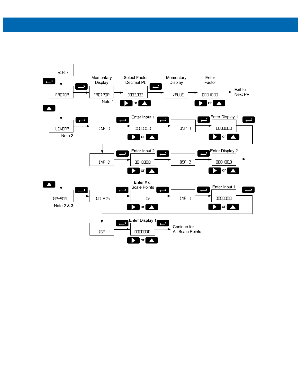
Scale Modbus PV to Engineering Units (SCALE)
The Modbus PVs may be scaled to reflect different engineering units than the data read out of the Modbus slave
device register. To do this, use the Scale menu to select the type of scale desired.
Note 1: The bottom display of the feet and inches display models does not show decimal points. While the decimal
point may not appear, it is included on the factor programming steps.
For example: To enter a conversion factor of 2.54, select a factor decimal point with 2 decimal locations, and enter a
factor value of 254.
Note 2: MP-SCAL is only available when scaling PV1.
29
Page 30

PD6730X Field-Mount Modbus Scanners
Factor (FACTOR)
Factor scaling uses a conversion factor for scaling a
number of PV register counts to a single display
count. In other words, the factor acts as a multiplier to
change Modbus PV register data units into display
engineering units.
Factor Decimal Point (FACTR.DP)
Enter the number of decimal point locations necessary to
enter the conversion factor.
Conversion Factor Value (VALUE)
Enter the conversion factor; the multiplier value that is
applied to the Modbus PV register data to convert it to
the desired display engineering units.
For example: if the PV register data is a height in
centimeters, but a height in inches is desired on the
display, a factor of 0.393701 would be entered.
(Display Value) = (Modbus Register Value) * (Factor)
Example:
(386.08 cm) * (0.393701) = (152.00 in) = (12 ft 8 in)
Note: The bottom display of the feet and inches
display models does not show decimal points. While
the decimal point may not appear, it is included on the
factor programming steps.
For example: if the PV register data is 0 to 100 in a
flowmeter, but a flow rate desired on the display is 0
to 250 GPM, a factor of 2.5 would be entered. On feet
and inches display models, there is no lower display
decimal point. Therefore, a factor decimal point of 1
place is selected, and a conversion factor value of 25
is entered.
Instruction Manual
Linear (LINEAR)
Linear scaling is used to convert a linear scale of PV
to display value.
Input Values 1 and 2 (INP)
Enter the Modbus PV register data for scaling points
1 and 2.
Display Values 1 and 2 (DSP)
Enter the corresponding display values for input
points 1 and 2.
For example: If a PV register contains data in terms of
tank height in feet for a 100 feet tank, the display
value can be linearly scaled for an input of 0 feet
(Input 1) displaying 0 percent (Display 1), and an
input of 100 feet (Input 2) displaying as 100 percent
(Display 2).
Not available on Modbus PVs assigned to the feet
and inches display of feet and inches display models.
Multipoint Scaling (MP-SCAL)
This type of scaling is only available for PV1.
Multipoint Scaling is used when multiple linear scaling
points are required, such as round horizontal tanks or
conical storage silos. Up to 32 linearization points
may be entered, with linear scaling between each
point.
Not available on Modbus PV1 if assigned to the feet
and inches display of feet and inches display model.
Number of Points (NO PTS)
Enter number of linearization points. The default value
is 2 points. For linear inputs requiring only 2 scale
points, use Linear scaling.
30
Page 31
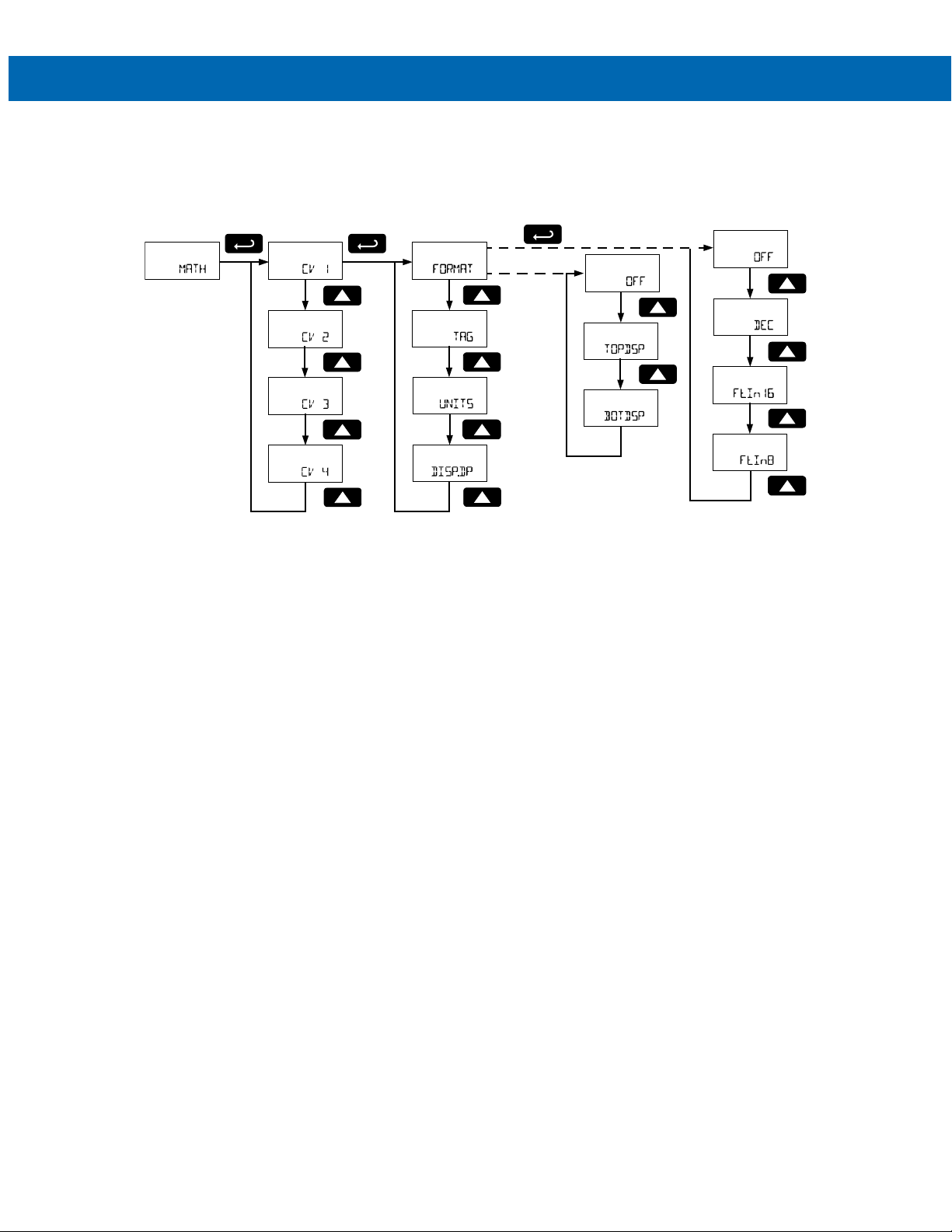
PD6730X Field-Mount Modbus Scanners
Note 2
Note 1
Ft & In Display
Decimal Display
Instruction Manual
Math Channel Display Setup (MATH)
The Math Channel Display Setup menu is used to configure the display options for each of the four math channels,
CV1 to CV4. The Menu will only display the math channels that have been enabled. See Math Channel (CV1 to CV4)
Programming (MATH) on page 41 for details on programming the math functions.
FORMAT
Note 1:
FORMAT
If
Note 2: Display Decimal Point menu is not applicable to feet and inches display format.
must be set to either
is set to
OFF
, these menus are not visible.
TOPDSP
or
BOTDSP
for the
TAG, UNITS
, and
DISP.DP
menus to be visible.
31
Page 32

PD6730X Field-Mount Modbus Scanners
Math Display Format (FORMAT)
The Math Display Format menu is used to configure
the display format for each math channel. The Math
Display Format must be set to display on either the
top or bottom display for the TAG, UNITS and DISP.DP
menus to appear.
Decimal Display Models
The math channel value may appear on the top
display (TOPDSP) or bottom display (BOTDSP). The
math channel value may also be turned off (OFF), and
will not display, though it may be used in other math
functions.
Feet and Inches Display Models
The math channel may appear on the top feet and
inches display with 1/16 of an inch (FtIn16), 1/8 of an
inch (FtIn8), or appear on the 7-digit bottom display
(DEC) with no decimal points. The math channel may
also be turned off (OFF), and will not display, though it
may be used in other math functions.
Press Enter to access the Format menu and Up but-
ton to scroll through choices.
Press Enter to make a selection and proceed to the
next menu.
Press the Menu button to back out of a menu or hold
the Menu button to exit at any time.
Instruction Manual
Set Display Decimal Point (DISP.DP)
Select the display decimal point location for the math
channel value. To program the math channel display
decimal point location, select the Display Decimal
Point menu and press Enter.
Decimal Display Models
Set the display decimal point location for the math
channel. Pressing the Right arrow moves the decimal
point one place to the right (including no decimal
point). Pressing the Up arrow moves the decimal
point one place to the left. Press Enter to confirm the
number of decimal points and continue programming.
Feet and Inches Display Models
Feet and inches display models do not have this
menu. On feet and inches display models, this value
is fixed, the top display PVs showing feet and inches
and the bottom display PVs showing no decimal
location.
Enter Math Channel Tag (TAG)
Each math channel may have a unique programmable tag to identify the math channel while the display
is scanning. To program the tag, select the Tag menu
and press Enter.
Program the custom tag as described in Setting Al-
phanumeric Labels (LABEL) on page 18. When the label has been programmed, press Enter to confirm the
label and leave the Tag parameter. Press the Menu
button to back out of a menu or hold the Menu button
to exit at any time.
Enter Math Channel Units (UNITS)
Each math channel may have a unique engineering
unit identifier to display while scanning. To program
the units, select the Units menu and press Enter.
Program the custom unit as described in Setting Alphanumeric Labels (LABEL) on page 18. When the label has been programmed, press Enter to confirm the
label and leave the Units parameter.
Press the Menu button to back out of a menu or hold
the Menu button to exit at any time.
32
Page 33

PD6730X Field-Mount Modbus Scanners
Tank Size Indicator (TANKSZ)
The Tank Size menu defines the 100% full level for
the 20-segment tank level indicator on feet and inches
display models. This menu is not present in decimal
display models. All PV values displayed on the top
line feet and inches display will use this tank level indicator.
To set the maximum height of the tank level indicator,
enter the level for thank to display as full. Enter the
full value in feet.
See Setting Numeric Values on page 18 for more in-
formation on entering the tank full level in feet.
Press Enter to confirm and save the tank level indicator full value.
Tag Display Time (T-TAG)
If either display is set to toggle a custom tag as part of
the Top Display or Bottom Display programming the
scanner will prompt for a toggle time with this menu.
The custom tag for each variable will display before
each variable for a number of seconds set by this
parameter. The tag may be programmed to display for
1 to 49 seconds.
Press Enter to access the Tag Display Time menu.
Use the Up and Right buttons to enter the tag display
time. Press Enter to make a selection and proceed to
the next menu. See Setting Numeric Values on page
18 for more information.
Press the Menu button to exit without saving changes.
Instruction Manual
Units Display Time (T-UNITS)
If either display is set to toggle units as part of the Top
Display or Bottom Display programming the scanner
will prompt for a toggle time with this menu.
The unit for each variable will display before each variable for a number of seconds set by this parameter.
The unit may be programmed to display for 1 to 49 seconds.
Press Enter to access the Units Display Time menu.
Use the Up and Right buttons to enter the units display time. Press Enter to make a selection and proceed to the next menu. See Setting Numeric Values
on page 18 for more information.
Press the Menu button to exit without saving changes.
Scan Time (T-SCAN)
The scan time defines how long a variable will be
shown on the display while automatically scanning.
After the scan time has elapsed, the next tag, unit,
and variable will be displayed.
The scan time may be programmed to cycle the
display to the next variable every 2 to 99 seconds.
Press Enter to access the Scan Time menu. Use the
Up and Right buttons to enter the scan time. Press
Enter to make a selection and proceed to the next
menu. See Setting Numeric Values on page 18 for
more information.
33
Page 34
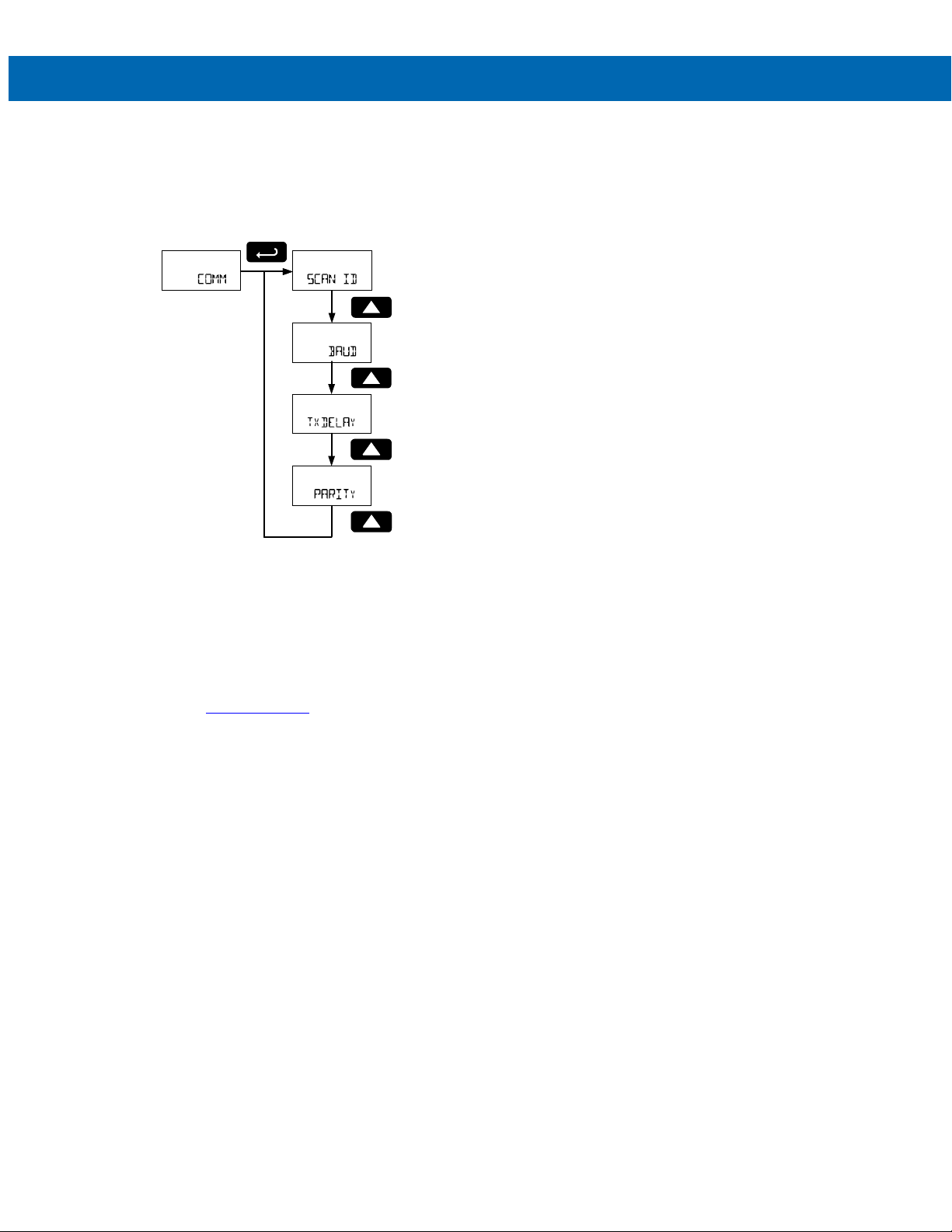
PD6730X Field-Mount Modbus Scanners
Serial Communications Settings
COMM)
(
The Serial Communications menu is used to setup se-
rial communications parameters necessary for communication via the RS-485 connection and Modbus.
Instruction Manual
Scanner Modbus ID (SCAN ID)
The Scanner Modbus ID menu sets the Modbus address (ID) of the scanner. The scanner Modbus ID
may be programmed between 1 and 247. When using
more than one device in a multi-drop mode, each device must be provided with its own unique address.
To program the Modbus ID, refer to Setting Numeric
Values on page 18.
Baud Rate (BAUD)
The baud rate may be set to 1,200; 2,400; 4,800;
9,600; 19,200; 38,400; 57,600; or 115,200 bps.
In the Baud Rate menu, use the Up button to scroll
through the menu choices.
Press Enter to make a selection and proceed to the
next menu.
Transmit Delay Time (TXDELAY)
The transmit delay may be set between 0 and 199 ms.
To program the transmit delay time, refer to Setting
Numeric Values on page 18.
Press Enter to access the Serial Communications
Settings menu then press the Up to scroll through the
menu choices.
Press Enter to select a menu. Press Menu to back
out of a menu or hold Menu to exit at any time.
Modbus communications is performed with the 3-wire
(including Ground) RS-485 connector.
Refer to the PD6730X Scanner Modbus Register Tables located at www.predig.com
information.
for additional Modbus
Parity (PARTIY)
The parity can be set to even (EVEN), odd (ODD), or
none with 1 (NONE1) or 2 (NONE2) stop bits.
In the Baud Rate menu, use the Up button to scroll
through the menu choices.
Press Enter to make a selection and proceed to the
next menu.
34
Page 35
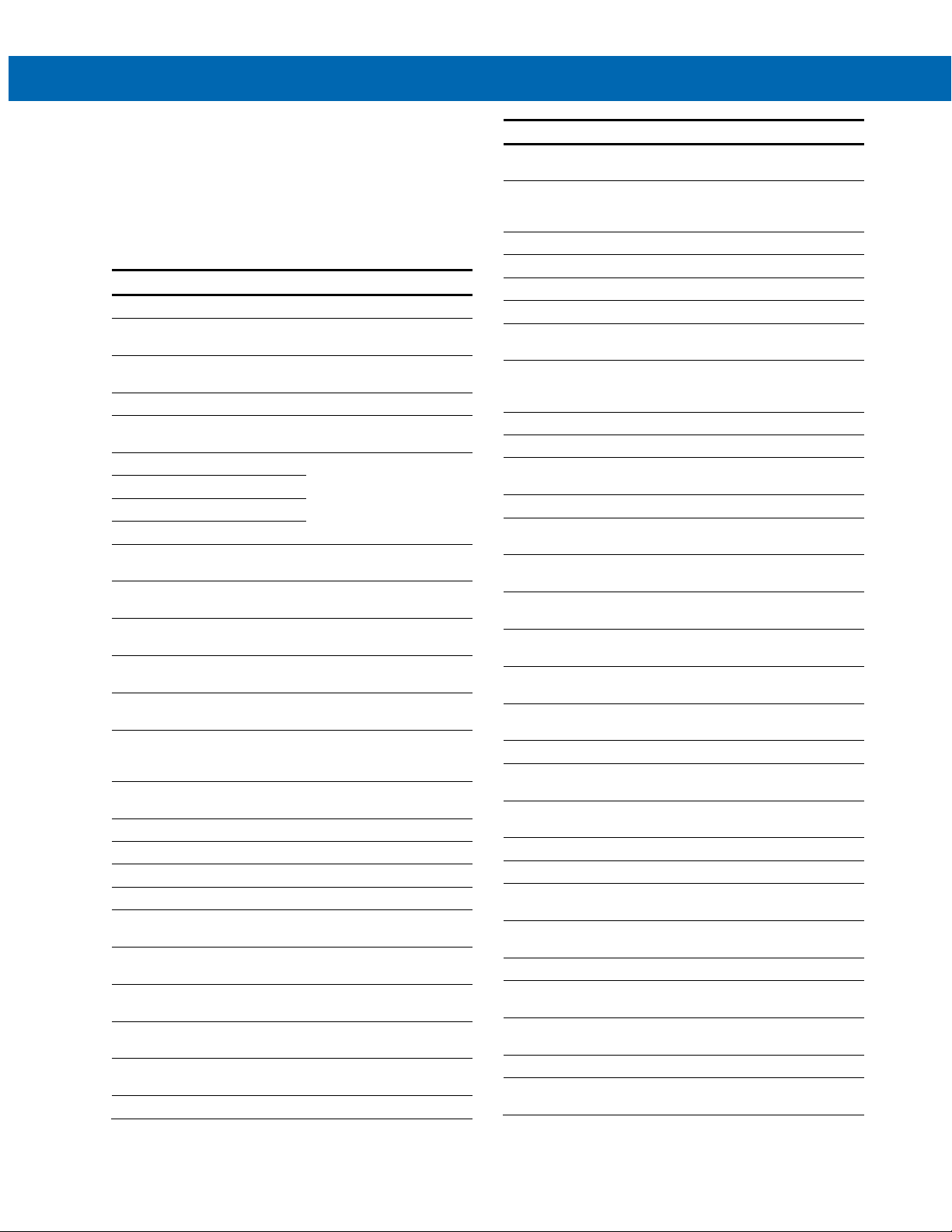
PD6730X Field-Mount Modbus Scanners
Display
Parameter
Action/Setting
ADVANCE
pulse output mode
Advanced Menu
Display Functions & Messages
The scanner displays various functions and messages
during setup of advanced features. The following table
shows the Advanced Features menu functions and
messages in the order they appear in the menu.
OUTPUT
OUT 1
OFF
PULSE
RATE
TOTAL
GrTOTAL
RETRAN
QUAD
TEST
PV
SORUCE
ALARM
PV NUM
PV 1
SET
RESET
ON
OFF
TIMER
Start
PERIOD
TIME
OUT 2
A OUT
Advanced Enter Advanced menu
Output Setup open collector
Output 1 Assign function of open
Off Disable output
Pulse Set Out 1 or Out 2 for
Rate Refer to pulse input
Total
Grand Total
Retransmit
Quadrature Assign pulse output to
Test Assign pulse output to test
Process
Variable
Source Set pulse output reference
Alarm
Process
Variable
Number
Process
Variable 1
Set Point Set alarm set point
Reset Point Set alarm reset point
On Set output to on state
Off Set output to off state
Timer
Start Activate timed pulse
Delay Set the time of one period
On Set the active low pulse
Output 2 Assign function of open
Analog Output Enter Analog Output menu
outputs Out 1 and Out 2
collector output 1
manual for any reference
to Rate, Total, or Grand
Total.
quadrature
mode
Assign pulse output to a
PV or CV
variable
Assign Out 1 or Out 2 for
alarm output mode
Assign alarm output to a
PV or CV
Select Process Variable to
assign alarm to (1-16)
Set Out 1 or Out 2 for
timed pulse output mode
output
(seconds)
width time
collector output 2
Instruction Manual
Display Parameter Action/Setting
SOURCE
PV1
DSPLY 1
OUt 1
DSPLY 2
OUt 2
SAVE?
CV1
DISABLE
MATH
CV 1
MULTI
PAR1
PAR2
PAR3
L2P1
L2P2
L2P3
DIVIDE
DIFABS
WAVG
DRAW
RATIO
CONCEN
CONST
NONE
ABS
SQRT
SUM
DIF
Source
Process
Variable 1
Display 1 Output display 1 value
Output 1 Output 1 value
Display 2 Output display 2 value
Output 2 Output 2 value
Save
Math
Channel 1
Disable Turn off the analog output
Math Enter Math menu
Math
Channel 1
Multiply Set math to multiply
Parameter 1 Enter math function
Parameter 2
Parameter 3
Level 2
Parameter 1
Level 2
Parameter 2
Level 2
Parameter 3
Divide Set math function to divide
Absolute
Difference
Weighted
Average
Draw Set math function to draw
Ratio Set math function to ratio
Concentration Set math function to
Constant Set math function to a
None Set math function to none
Absolute Value Set math function to
Square Root Set math function to
Sum Set math function to sum
Difference
Set analog output
reference variable
Set PV as analog output
source, can select any
active PV (1-16)
Save entered analog
parameters
Set CV as analog output
source, can select any
active CV (1-4)
Program math channel
(Channel 1-4)
parameter 1
Enter math function
parameter 2
Enter math function
parameter 3
Enter nested math function
level 2 parameter 1
Enter nested math function
level 2 parameter 2
Enter nested math function
level 2 parameter 3
Set math function to
absolute difference
Set math function to
weighted average
concentration
constant value
absolute value
square root
Set math function to
difference
35
Page 36

PD6730X Field-Mount Modbus Scanners
October
Set month as October
Backup
Enter Backup menu
Display Parameter Action/Setting
GATE
FILTER
CUTOFF
SCALCAL
T RESET
PASSWRD
UNLOCKD
LOCKED
Pass
UnLOC
LOCD
Pass T
Pass GT
CUSTOM
POS 1
SYSTEM
SETTIME
YEAR
MONTH
01
02
03
04
05
06
07
08
09
10
11
12
DAY
TIME
DATALOG
LOGTIME
LOG 1
Gate
Filter
Low-Flow
Cutoff
Scale &
Calibrate
Total Reset
Password Enter the Password menu
Unlocked Program password to lock
Locked
Password
Unlock
Lock Password has been locked
Password
Total
Password
Grand Total
Custom Enter Custom menu
Position 1 Set menu position 1 (1-8)
System Enter System menu
Set Time Set real-time clock date
Year Set the year
Month Set the month
January Set month as January
February Set month as February
March Set month as March
April Set month as April
May Set month as May
June Set month as June
July Set month as July
August Set month as August
September Set month as September
November Set month as November
December Set month as December
Day Set the day
Time Set the hour and minute
Data Log Enter Data Log menu
Log Time Set daily data log times
Log 1 Set first daily log time
Refer to pulse input
manual
scanner
Enter password to unlock
scanner
Program password to lock
scanner parameters
Password has been
unlocked
Refer to pulse input
manual
and time
(1-4)
Instruction Manual
Display Parameter Action/Setting
DISABLE
ENABLE
INTERVL
FULSTOP
CONT
START
LOGVIEW
LOGVIEW
ALL
ERASE
ERASE
ALL?
BAKLITE
ENABLE
DISABLE
AO CAL
Disable Disable log number
Enable Enable log number
Interval Set interval log time
Stop When
Full
Continue Data logging will continue
Start Begin interval logging
Log View View data log
All Log View View all data log points
All Erase Erase all logs
Erase? Confirm to erase all logs
Backlight Enable or disable backlight
Disable Disable backlight
Enable Enable backlight
Analog Output
Calibration
Data logging will stop
when the log is full
when the log is full,
deleting old data
Enter Analog Output
Calibration menu
BACKUP
SAVE?
LOAD?
DEFAULT
DFALTS?
INFO
SOFT
VER
MODEL
Save? Save current parameters
Load? Load parameters from
Default Restore factory default
Reset Defaults Confirm factory reset
Info Enter Info menu
Software
Version
Model Display model number
to backup restore
backup restore
parameter settings
Display software ID
number
Display software version
number
36
Page 37
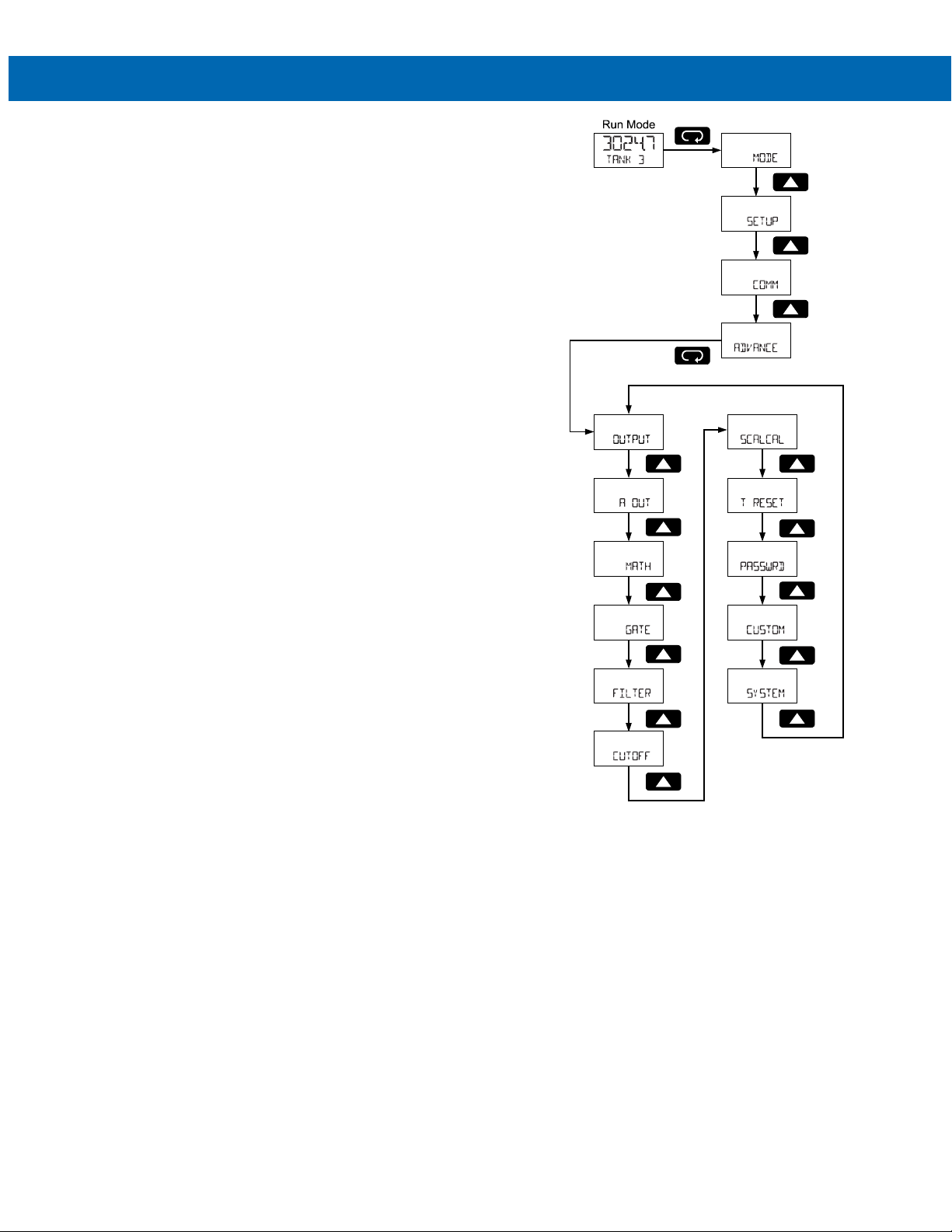
PD6730X Field-Mount Modbus Scanners
Note 1
Note 2
Note 2
Note 2
Note 2
Note 2
Advanced Menu Programming
ADVANCE)
(
To simplify the setup process, functions not needed for
most applications are located in the Advanced menu.
Access the Advanced menu features by pressing Enter
at the Advance menu in the Main Menu defined on
page 19.
Press the Enter button to access any menu or press
the Up arrow button to scroll through choices.
Press the Menu button to back out of a menu or hold
the Menu button to exit at any time.
The Advanced menu is used to select:
• Open Collector Output Configuration
(OUTPUT)
• Analog Output Configuration (A OUT)
• Math channel functions (MATH)
• Set Passwords (PASSWRD)
• Reconfigure the Main Menu Structure
(CUSTOM)
• Enter the System Menu for Scanner
Operation and Data Logging (SYSTEM)
Instruction Manual
A OUT
Note 1: Analog Output (
for scanners with the analog output option.
Note 2: Refer to pulse input manual
37
) menu displayed only
Page 38
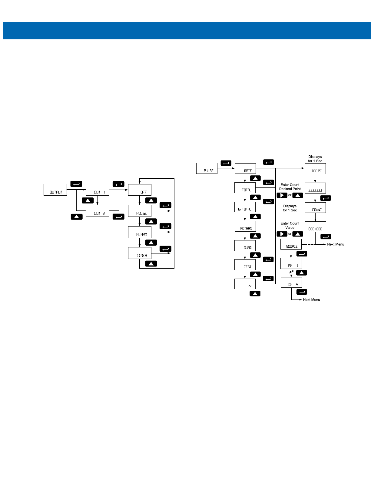
PD6730X Field-Mount Modbus Scanners
Note 1
Note 2
Note 2
Note 2
Note 2
Open Collector Outputs (OUTPUT)
The scanner is equipped with two NPN open collector
outputs that may be set up for pulse outputs, alarms,
timed pulses, or turned off.
Pulse outputs can be based on a Modbus PV value,
or math channel value. Both outputs may be used to
generate a quadrature output based on any pulse
menu output type. An output test mode is also selectable to generate pulses at a constant programmable frequency.
Alarms are available based on a Modbus PV or math
channel. The alarm status will show on the display
even if the output is not wired. The outputs may also
be forced on or off.
A timed pulse output generates constant pulses at a
specified frequency and on time.
The output may be disabled by selecting Off.
Instruction Manual
Output 1 and 2 Setup (OUT 1, OUT 2)
The function of open collector output 1 and 2 is configured using the Off (OFF), Pulse (PULSE), Alarm
(ALARM), and Timer (TIMER) menus detailed below.
In the Output 1 and 2 menus, use the Up button to
scroll through the menu choices.
Press Enter to make a selection and proceed to the
next menu.
See Setting Numeric Values on page 18 for more in-
formation on programming numeric count, set, and reset value.
Pulse Output (PUlse)
Pulse outputs may be assigned to Modbus PV (PV),
math channel (CV), quadrature (QUAD), or test (TEST).
Note 1:
SOURCE
menu only applicable to PV option.
Note 2: Refer to pulse input manual
38
Page 39
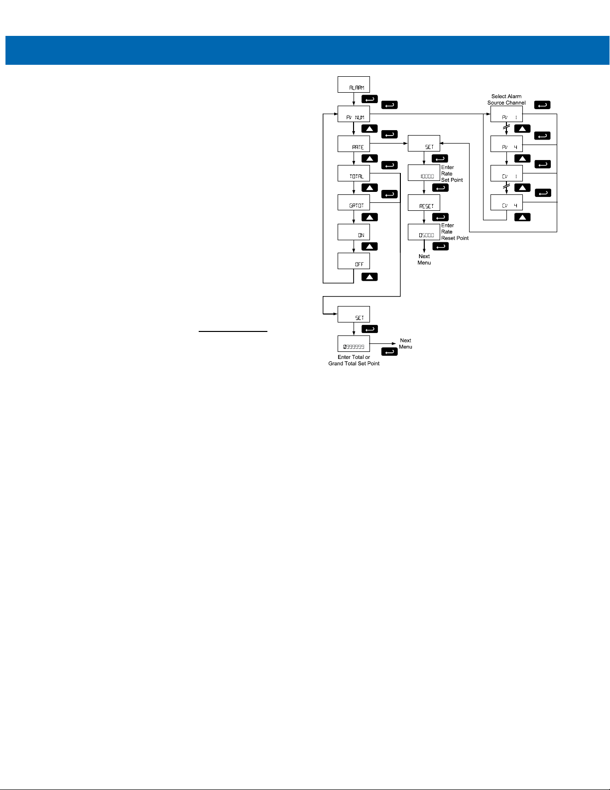
PD6730X Field-Mount Modbus Scanners
Note 1
Note 1
Note 1
Quadrature Pulse Output (QUAD)
The pulse output set to quadrature will duplicate the
other open collector output, but lag by ¼ duty cycle
(90 degrees out of phase). For example, Out 1 will
follow Out 2, if Out 1 is set to QUAD. Only one output
should be set to QUAD. If both outputs are set to QUAD,
both outputs will be disabled. The other output should
be programmed as desired for the quadrature output
function, and must be a pulse (PUlse) output
selection.
Test Pulse Output (test)
The test output setting programs the output to
generate pulses at a programmed constant
frequency. Set the frequency decimal point location in
the DECPT menu, and then enter the desired output
frequency in Hz in the PULSE menu.
Modbus PV or Math Pulse Output (PV)
The pulse output may be based on an enabled
Modbus PV or math channels CV1 to CV4. The pulse
output frequency in hertz (Hz) is calculated as the
value of the selected PV or CV divided by the
programmable count (or divisor).
(
()=
The frequency of the pulse output will update as the
PV or CV value is changed.
For example, if the output is set to reference PV 2,
and PV 2 is reading 1540.5, with a count or 10, the
pulse output frequency will be 154.05 Hz.
Alarm Output (ALARM)
Alarm outputs may be assigned to Modbus PV or
math channel (PV NUM), always on (ON) or always off
(OFF).
)
Instruction Manual
Note 1: Refer to pulse input manual
Modbus PV or Math Alarm (PV NUM)
Program a PV (PV1-16) or math channel (CV1-4) to
trigger an alarm. Select the source PV or CV for the
alarm and enter the display value set and reset
points. The alarm deadband is determined by the
difference between set and reset points. Minimum
deadband is one display count. If set and reset points
are programmed the same, output will reset one count
below set point.
39
Page 40
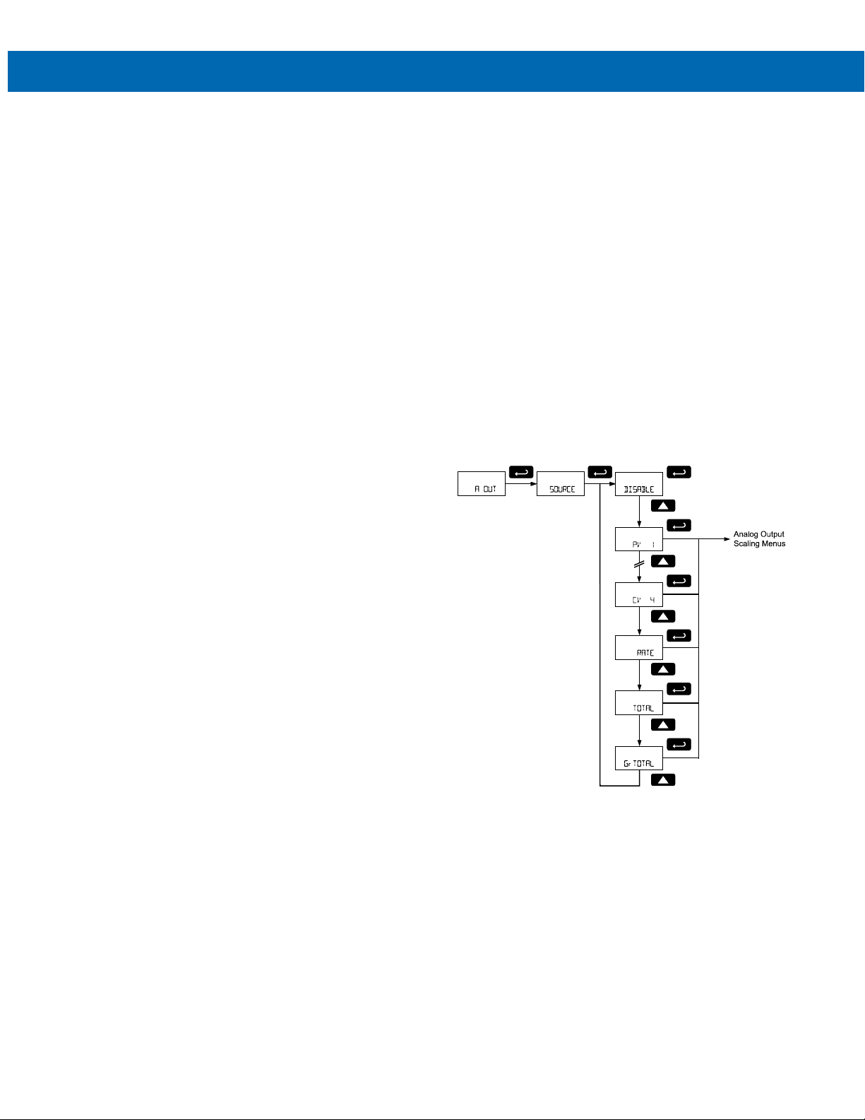
PD6730X Field-Mount Modbus Scanners
Note 1
Note 1
Note 1
Force On State (ON)
This alarm mode forces the output to be active, or on.
This mode is primarily used to test alarm systems.
Force Off State (OFF)
This alarm mode forces the output to be inactive, or
off. This mode is primarily used to test alarm systems.
Timer Output (TIMER)
The timer output produces a constant pulse width at a
constant frequency. Program the Period (PERIOD)
from 0.1 to 999999.9 seconds (time from the start of
one pulse to the start of the next pulse).
Program the On Time (TIME) for the active low pulse
from .01 to 99999.99 seconds (pulse width). The on
time must be less than the delay time (Period).
Select Start (START) to begin outputting the constant
timed pulse.
Select Stop (STOP) to end outputting the constant
timed pulse.
Instruction Manual
Scaling the 4-20 mA Analog Output (Aout)
The Analog Output menu is used to program the
4-20 mA output based on display values. This menu
is not present on models without a 4-20 mA output
option.
The 4-20 mA analog output (if equipped) can be
scaled to provide a 4-20 mA signal for any display
range selected for either Modbus PV 1 to 16 or math
channel CV 1 to 4.The output may be disabled (DISA-
BLE), and it will only output the minimum signal.
No equipment is needed to scale the analog output;
simply program two display values and corresponding
mA output signals.
Selecting the Analog Output Source
In the Analog Output (A OUT) menu, press the Enter
button. In the Source (SOURCE) menu, press the Up
button to scroll through the menu choices.
Press Enter to make a selection and proceed to the
next menu.
Note 1: Refer to pulse input manual
40
Page 41
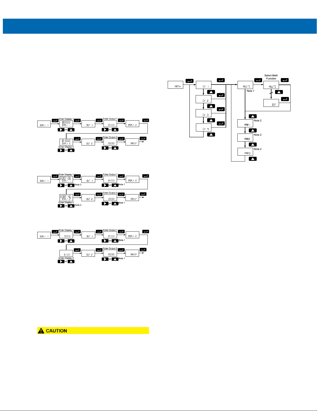
PD6730X Field-Mount Modbus Scanners
Enter Display and Output Values
To scale the analog output, enter display value 1 and
a corresponding analog output value for this display,
and enter display value 2 and a corresponding analog
output value for this display value. This will provide a
linearly scaled analog output.
On decimal display models, enter the output value in
mA. On feet and inches display models, enter the output value in µA.
The following diagram details setting the analog output when the source is configured to display on the
top display of a decimal display model.
The following diagram details setting the analog output when the source is configured to display on the
top display of a feet and inches display model.
The following diagram details setting the analog output when the source is configured to display on the
bottom display.
Instruction Manual
Math Channel (CV1 to CV4) Programming (MATH)
The scanner includes four math channels, CV1 to
CV4. Each math channel is constructed by selecting a
math function and the desired parameters.
Note 1: The current math function selection will display as this menu item.
Note 2: Parameter 1, 2, and 3 will appear in the menu
structure based on their use in the selected math
function. See the table below for information on what
parameters are necessary for each math function. If
Constant is selected as the math function, the value
will be immediately entered.
See Setting Numeric Values on page 18 for more in-
formation on programming the display and output values.
Note 1: On decimal display models, enter the output
value in mA. On feet and inches display models, enter
the output value in µA.
Note 2:The hundreds digit on the feet display does
0
not display 0 as a seven-segment
represented with three horizontal bars as shown.
• Please note that when power is removed from the
scanner, the analog output will drop below 1 mA.
• Consider this effect when designing any system
using the 4-20 mA output.
; instead 0 is
41
Page 42

PD6730X Field-Mount Modbus Scanners
Selection
Square Root
√(PAR1)
PAR
also selectable
The available math functions are detailed below.
Math
SUM
DIF
MULTI
DIVIDE Division PAR1 / PAR2
DIFABS
WAVG
DRAW
RATIO
CONCEN
CONST
NONE None Disable
ABS
SQRT
Function Equation
Addition PAR1 + PAR2
Difference PAR1 - PAR2
Multiplication PAR1 * PAR2
Absolute diff. Abs(PAR1 - PAR2)
Weighted
avg.
Draw
Ratio (PAR1 / PAR2) * PAR3
Concentration
Constant
Absolute
Value
((PAR1 –
PAR2)*PAR3) +PAR2
((PAR1 / PAR2) –
1) * PAR3
PAR1 / (PAR1 +
PAR2) * PAR3
Constant value of
0.0001 to 99999
Abs(PAR1)
Instruction Manual
The available parameters for PAR1, PAR2, and PAR3
shown above are detailed below.
Parameter Description
Selection
The scaled PV1 value;
PV 1
CV 1
ABS
SQRT
SUM
DIF
MULTI
DIVIDE
DIFABS
WAVG
DRAW
RATIO
CONCEN
CONST Constant
NONE None No parameter.
*Selecting this math function as a parameter will enter
into the setup for a Nested Math Function. These parameters are not available for level 2 parameters used
when setting up the nested math function.
Modbus PV1
Math Channel
CV1
Nested
Absolute
Value*
Nested
Square Root*
Nested
Addition*
Nested
Difference*
Nested
Multiplication*
Nested
Division*
Nested
Absolute diff.*
Nested
Weighted
avg.*
Nested Draw*
Nested Ratio* (L2P1 / L2P2) * L2P3
Nested
Concentration*
PV2 to PV16 also
selectable
The math channel CV1
value; CV2 to CV4
Abs(L2 PAR1)
√(L2 PAR1)
L2P1 + L2P2
L2P1 - L2P2
L2P1 * L2P2
L2P1 / L2P2
Abs(L2P1 - L2 PAR2)
((L2P1 – L2P2)* L2P3)
+ L2P2
((L2P1 / L2P2) – 1) *
L2P3
L2P1 / (L2P1 + L2P2)
* L2P3
Constant value of
0.0001 to 99999
Nested Math Functions
To create more complicated math functions, the first
level parameters allow a math function to be selected
as the parameter. In this case, a second level of
parameters is selected for the nested math function.
These level 2 parameters are level 2 parameter 1,
L2P1 (L2P1), level 2 parameter 2, L2P2 (L2P2), level
2 parameter 3, and L2P3 (L2P3). Level 2 parameters
are selected similarly to other math parameters;
however additional nested math functions are
unavailable for selection.
42
Page 43
PD6730X Field-Mount Modbus Scanners
Model
Password
Entering a Constant Value
To enter a constant value, press Enter to select
Constant (CONST). Value (VALUE) will display. Press
Enter to confirm and enter a constant value. V.DP will
display. Use the Up and Right arrows to select the
number of decimal points used in the constant value.
Press Enter to select the number of decimal points
selected. Value will display. Set the constant value.
See Setting Numeric Values on page 18 for more
information.
No Parameter (NONE)
Selecting a parameter of None will disable the math
function. Any math function with a parameter of None
will display None (NONE) on the display as the value of
the math function.
Setting Up Passwords (PASSWRD)
The Password menu is used to program a five-digit
password to prevent unauthorized changes to the programmed parameter settings.
The lock symbol is displayed on decimal display models to indicate that settings are password protected.
Record all passwords for future reference. If appropriate, it may be recorded in the space provided.
For instructions programming numeric values see Set-
ting Numeric Values on page 18 for more information.
Instruction Manual
• Did you forget the passwords? The password
may be disabled by entering a master password.
If you are authorized to make changes, enter the
master settings lockout (PASS) password 50865,
to unlock the scanner.
Serial Number:
Setting Lockout
Password (PASS):
____ ____ ____ ____ ____
Locking Scanner Setup Parameters (PASS)
Enter the Password menu by pressing Enter. Select
Password (Pass) by pressing Enter. Program a five-
digit password. The scanner will return to Run Mode
after locking any of the passwords.
Making Changes to a Password Protected Scanner
If the scanner is password protected, the scanner will
display the message LOCKED when the Menu button is
pressed. Press the Enter button while the message is
being displayed and input the correct password
followed by the Enter button to gain access to the
menu. After exiting the programming mode, the
scanner returns to its password protected condition.
Disabling Password Protection
To disable the password protection, access the
Password menu, select the type of password to be
disabled, and enter the programmed password. That
password is now disabled until a new password is
entered.
43
Page 44
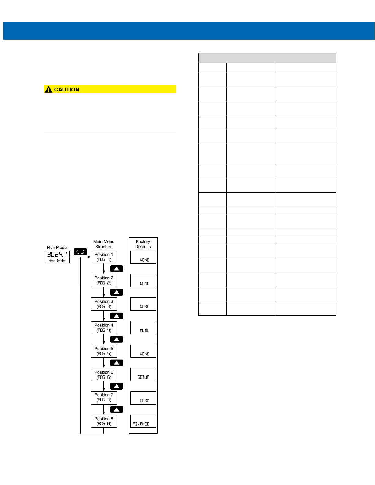
PD6730X Field-Mount Modbus Scanners
Set no menu position
display
Set to show Units
menu
Set to show Decimal
menu
Set to show Display
menu
Set to show
Output menu
Program password
parameters
Set to show Output
menu
Assign function of
pulse output 1
Assign function of
pulse output 2
Data Log
Enter Data Log menu
Set daily data log
times
Interval
Set interval log times
Log View
Enter Log View menu
Set to show
Password menu
menu
Set to show
Advanced menu
Set to show System
menu
Set to show Mode
menu
Custom (CUSTOM)
The Custom menu is used to modify the initial
programming menus that appear in the Main Menu
when the Menu button is pressed in Run Mode.
Display
NONE None
Parameter/Menu Action
Instruction Manual
Custom Menu Parameters
• Changing the default menu setup with the
Custom menu feature may change the setup and
operation procedures described in this manual.
Only operators familiar with the programming and
operation of this unit should use this feature.
Eight menu positions are available. Menu positions
6 and 7 are factory programmed for Setup and
Advanced.
After pressing Enter at the Custom menu, the display
will flash Position (POS 1) and then display the
parameter to appear in position 1 of the main menu.
To add a menu or parameter to the menu structure, or
change the default menus, press Enter at the desired
position (POS) to be edited, and use the Up or Right
arrows to select the desired menu item for that
position. Press Enter to save the setting. See the
Custom Menu Parameters chart for a complete list of
available menu selections for each position.
UNITS Units
DECIMAL
DISPLAY
A OUT Analog out
PASS
OUTPUT Output
OUT 1
OUT 2
DATALOG
LOGTIME Log Time
INTERVL
LOGVIEW
PASSWRD
SETUP
Decimal
Display
Password
Out 1
Out 2
Password
Setup
Analog
to lock scanner
Set to show Setup
ADVANCE Advance
SYSTEM
MODE
System
Mode
44
Page 45
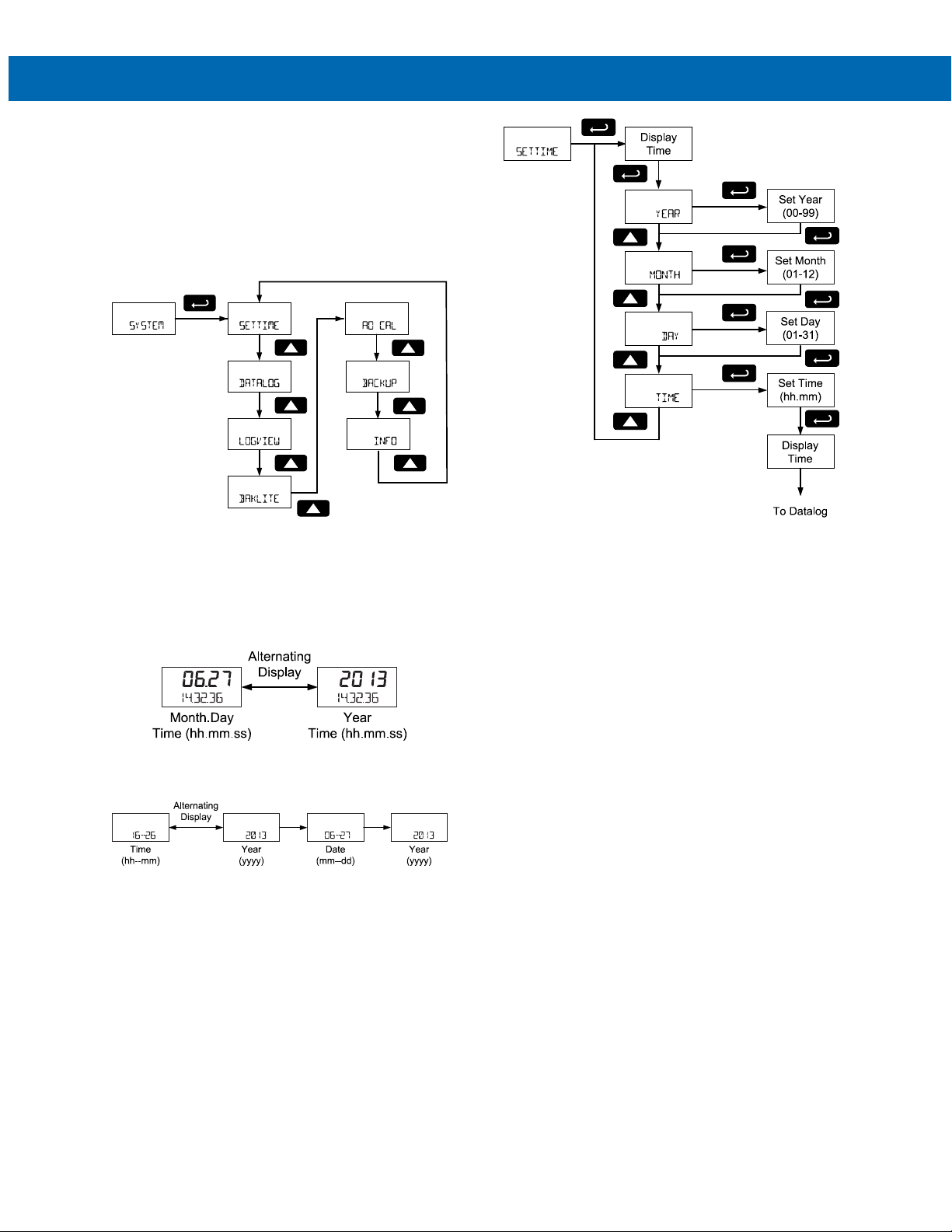
PD6730X Field-Mount Modbus Scanners
System (SYSTEM)
The system function is used to set the real time
clock, set daily data log times, enable/disable the
backlight, access analog output controls used in
troubleshooting, store, restore, and backup restore
feature, enable/disable the battery power alert symbol on the display, and review basic system identification information.
Instruction Manual
Set Real Time Clock (SETTIME)
The real time clock is used to trigger data log events,
and is recorded at every logged data point. The Set
Time menu displays the date and time.
Figure 10. Real Time Clock Display Example –
Decimal Model
Figure 11. Real Time Clock Display Example –
Feet & Inches Model
The above display examples show the date to be
June 27, 2013; at 14 hours, 32 minutes, and
36 seconds.
The year, month, day, hour, and minute may all be set
by the user. The real time clock will need to be reset if
external power and battery power are lost.
To program the time, select the time or date
component to be programmed, and press Enter. To
enter the time or date as a numeric value, see Setting
Numeric Values on page 18 for more information.
Changing the time (hours and minutes) will reset the
second clock to 0.
45
Page 46
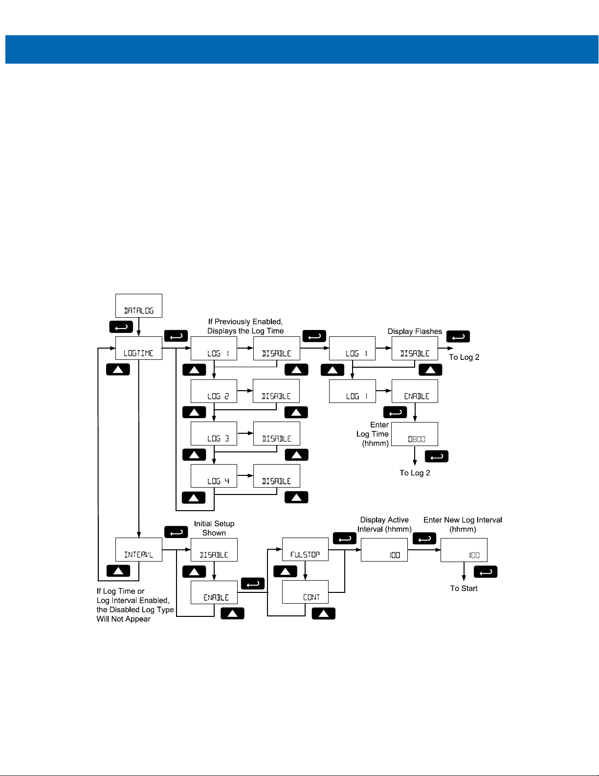
PD6730X Field-Mount Modbus Scanners
Data Log Setup (DATALOG)
The Data Log menu is used to setup and enable the
data log functions. The scanner may contain up to
511 records, each containing the date, time, and log
number. Each record may hold the first eight enabled
Modbus PVs and all enabled math channel CVs.
The data log can hold 511 records of the first eight
enabled Modbus PVs and math channel CVs.
The frequency of these records depends on the data
log settings.
For example: If PV 1, 2, 3, and 4 are enabled, and
CV 1 and 2 are enabled, the data log may record 511
logs containing PV 1, 2, 3, and 4, as well as CV 1 and
CV 2. The data log will record these values even if
CV2 is the only value set to display.
Instruction Manual
Log Time and Log Interval
There are two ways to configure the time when a data
log record is recorded. The Log Time feature allows
up to 4 data log events time to be entered for each
day. The Log Interval feature allows a data log recording event at the selected time interval. At each data
log event, all appropriate data records will be recorded.
Only the Log Time or Log Interval may be active at a
time. While one type of data logging is enabled, the
other menu is inaccessible.
46
Page 47
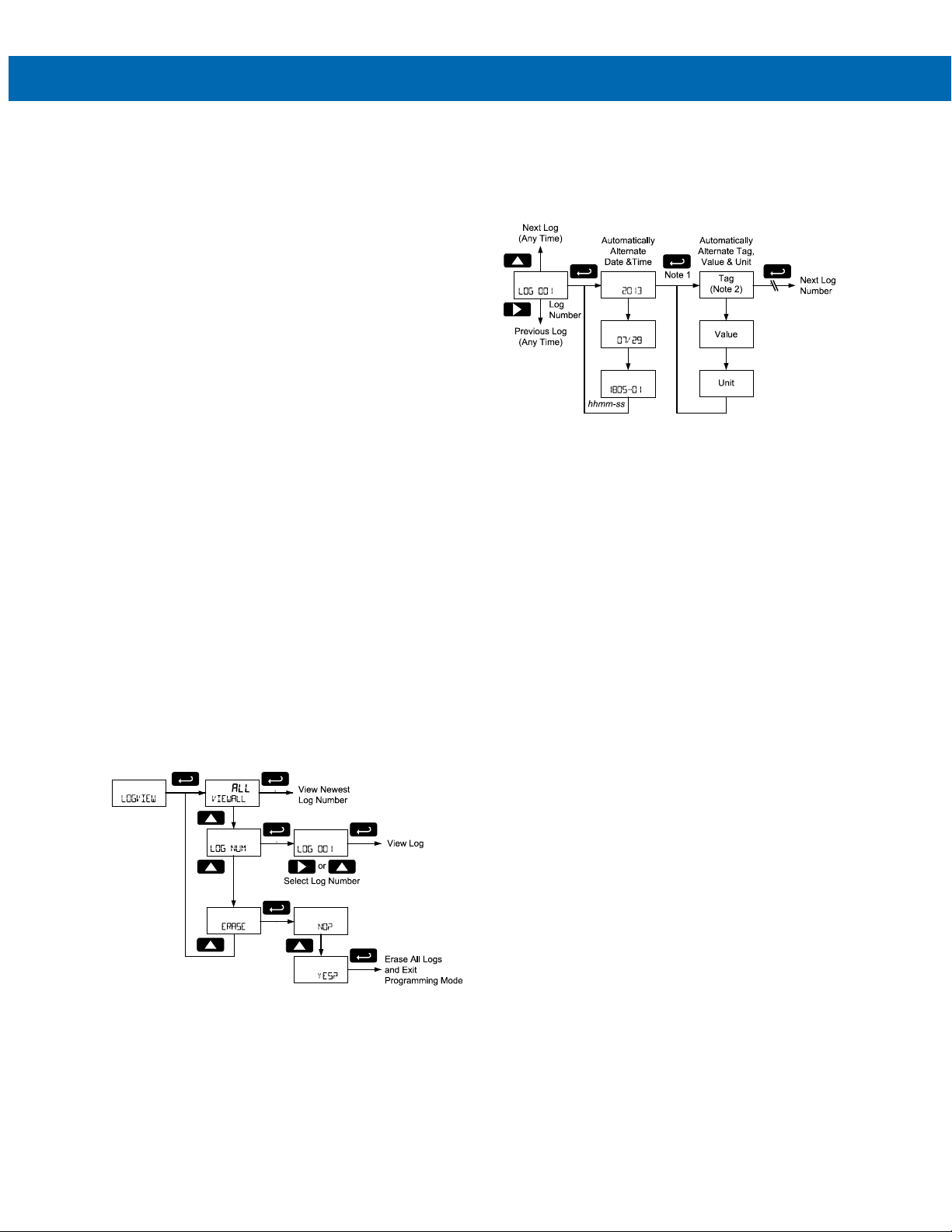
PD6730X Field-Mount Modbus Scanners
Log Time Setup (LOGTIME)
The Log Time menu contains four log events (LOG 1
to LOG 4). Each log time is configured independently.
For each daily log time desired, enable a log, and set
the log time for the hours and minutes the log is to be
recorded. The time is set in real-time hours and
minutes, based on the real time clock setup.
The Log Time feature will roll-over, deleting the oldest
data logs (in blocks of 8) when the log is full and new
logs must be recorded. This makes it the most useful
for long-term data logging.
Interval Setup (INTERVL)
The Interval menu sets the time interval for data logging. Every time interval, one data log event will be
recorded. To enable interval data logging, enable the
feature, and set the interval time for the hours and
minutes between each log.
If set to FULSTOP, the Log Interval feature will not de-
lete old data, and data logging will stop when the log
is full. This makes it the most useful for short periods
and logging specific functions.
If set to CONT, the Log Interval feature will delete the
old data when full and continue logging data. The Log
Interval feature will roll-over, deleting the oldest data
logs (in blocks of 8) when the log is full and new logs
must be recorded. This makes it the most useful for
long-term data logging.
View Data Log (LOGVIEW)
The Log View menu allows on-screen browsing of the
data log event records stored in the scanner. Data
points may be navigated by viewing the log number,
date and time, first eight enabled PVs and four CVs. A
known log may be jumped to immediately, avoiding a
lengthy search for data. All logs may be deleted with
the ERASE command, requiring confirmation.
Instruction Manual
Once the log records are displayed, use the Enter
key to display variable within the same log and move
to the next log. Use the Up and Right arrows to move
to the next or previous log number.
Note 1: All enabled PVs and CVs will display in order,
the Tag for each PV and CV will flash before displaying the value.
Note 2: All tags, values, and units will appear on the
lower display with exception of feet and inches formatted values on the feet and inches display models.
These parameters will automatically alternate on the
display.
Backlight (BAKLITE)
The Backlight menu is used to enable or disable the
backlight. After pressing Enter to access the Back-
light menu, press the Up arrow to Enable (ENABLE) or
Disable (DISABLE) for the backlight.
Analog Output Calibration (AO CAL)
This feature is only used at the factory. It is not recommended to access this menu without instruction
from technical support.
47
Page 48
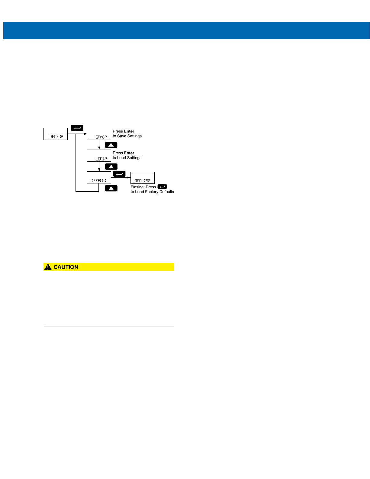
PD6730X Field-Mount Modbus Scanners
Backup & Restore (BACKUP)
The scanner saves all parameter settings, and no
reprogramming is necessary when power is lost and
restored to the scanner.
These features are used to save and restore
programmed settings. Programming can be restored
to a known saved good configuration, or to factory
defaults. This is useful to restore scanners whose
programming has been altered in unknown ways, or
to quickly restore known good settings if mistakes are
made during reprogramming.
The Save feature (SAVE?) saves all current parameter
settings into the memory of the backup restore. The
backup restore feature is loaded with factory default
settings until a new configuration is saved.
The Load feature (LOAD?) restores all parameters to
the programmed values stored in backup restore
memory. The Load feature will not affect the current
password settings.
Instruction Manual
Information (INFO)
The Information menu is part of the System features
menu. It shows software identification number,
version number, and extended model number. To
view this information:
Go to the Information menu (INFO) and press Enter
button.
Continue pressing Enter to scroll through the
displays.
Following the information display, the scanner will exit
the Advanced features menu and return to run mode.
• Once scanner parameters have been saved to
memory by the backup restore feature there is
no recovering the previously saved settings.
• Once parameters have been loaded into the
scanner from the backup restore feature there
is no recovering the previously programmed
settings.
The Default feature (DEFAULT) restores all parameters
to the factory default values. Factory default reset
does not change the saved backup restore settings,
or override passwords.
In the Backup menu, use the Up arrow key to select
the desired menu. Press Enter to execute the save,
load, or restore defaults command. To restore the
scanner to factory defaults, press Enter again to
confirm the request when Defaults? (DEFLTS?) is
blinking.
48
Page 49
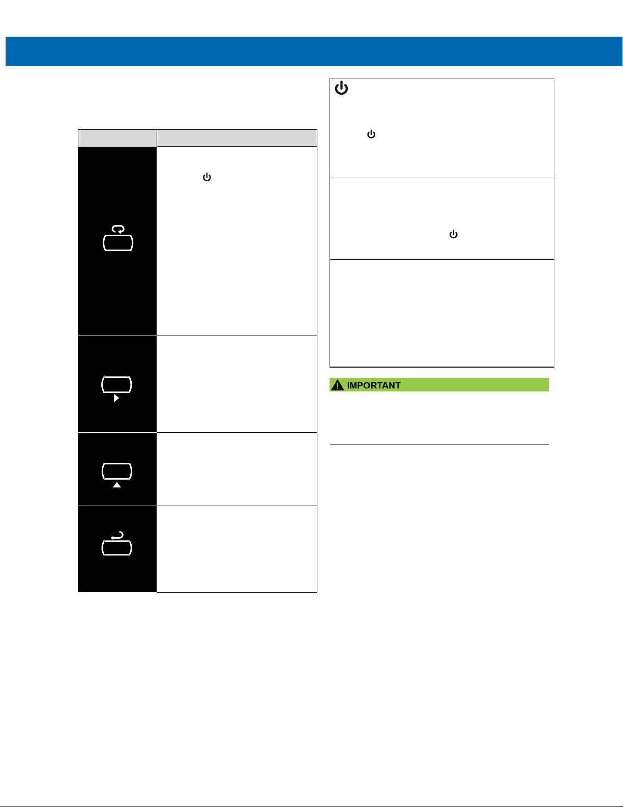
PD6730X Field-Mount Modbus Scanners
the Safe Touch buttons will be fully enabled.
SafeTouch Disabled Mode
chanical pushbutton being pressed.
SafeTouch Button Equalize Delay
being unblocked.
MENU
PREV
NEXT
SCAN
Instruction Manual
Operation
Front Panel Buttons Operation
Symbol Description
See SafeTouch Buttons on page 15 for setup.
SafeTouch Button Operation
To actuate a button, press and remove one finger to
the window directly over the marked button area. Remove finger to at least 4 inches away from the window
in between button activations. SafeTouch and mechanical buttons may be held to cycle through menus or digits in place of repeatedly pushing a button.
Hold the Menu SafeTouch button
when in power save mode (display
will show ) to awaken SafeTouch
buttons.
Press the Menu button to enter
Programming Mode.
Press the Menu button during
Programming Mode to return to the
previous menu selections.
Hold the Menu button for 1.5
seconds at any time to exit
Programming Mode and return to
Run mode.
Press and hold the Menu button for
3 seconds to access the Advanced
features menu.
Press Previous to manually display
the previous PV or input display.
Press the Right arrow button in
programming mode to move to the
next digit or decimal position.
Press the Right arrow button in
programming mode to go backward
through most selection menus.
Press Next to manually display the
next PV or input display.
Press the Up arrow button in
programming mode to scroll forward
through the menus, decimal point, or
to increment the value of a digit
Press Scan to pause automatic
scanning.
Press Scan to resume automatic
scanning when paused.
Press the Enter button in
programming mode to access a
menu or to accept a setting.
SafeTouch Power Save Mode
(Symbol shown on -2 decimal models only)
SafeTouch buttons enter a power saving mode after three
minutes of inactivity. This mode is indicated by a power
symbol ( ) appearing in the lower right of the display.
Only the MENU button is monitored in this mode. To activate the SafeTouch buttons, press and hold the menu button for up to five seconds. The display will read AWAKE, and
When the cover is removed, the four mechanical buttons
located next to the sensors may be used. The sensors are
disabled when a mechanical button is pressed and will
automatically be re-enabled after 60 seconds of inactivity.
The SafeTouch power symbol ( ) will blink in the lower
right of the display if the buttons are disabled due to a me-
The SafeTouch buttons are designed to constantly recalibrate for ambient conditions. When the cover position is
changed, the cover is removed, or an object is removed
that was placed over the front window, it may take a moment for the SafeTouch buttons to recalibrate to the
change in conditions.
Allow up to 2 minutes for the SafeTouch buttons to
recalibrate to new conditions in these cases where the
cover position was changed, or the front window is
• SafeTouch will not work if two or more buttons are
detected as being pressed simultaneously. Be careful
to avoid triggering multiple buttons or reaching across
one button location to press another.
SafeTouch Button Tips and Troubleshooting
The SafeTouch Buttons are designed to filter normal
levels of ambient interference and to protect against
false triggering, however it is recommended that the
Safe Touch
BUTTONS switch to OFF) if there is an infrared interference source in line-of-sight to the display or if the
buttons are not needed.
SafeTouch Button Tips:
Buttons be turned off (slide THRU-GLASS
• To the extent possible, install the display
facing away from sunlight, windows,
reflective objects, and any sources of
infrared interference.
• Keep the window clean.
• Tighten the cover securely.
• Use a password to prevent tampering.
• If the cover has not been installed and
secured tightly, it may take a moment for the
SafeTouch buttons to properly self-calibrate
when the cover is tightened.
• After all connections have been completed
and verified, connect the ribbon cable to the
display module, fasten the display module to
the base, install enclosure cover, and then
apply power.
49
Page 50

PD6730X Field-Mount Modbus Scanners
Instruction Manual
Pause/Start Automatic Scanning
Automatic scanning will cycle through the enabled
Modbus PVs and math channel CVs. The time each
variable will be displayed is programmed in the Scan
Time (T-SCAN) menu on page 33.
To pause scanning on the displayed variable, press
the Scan button.
To start scanning again, press the Scan button.
Manual Scanning
The enabled Modbus PVs and math channel CVs can
be manually cycled onto the display using the Next
and Previous buttons.
The Next button will display the next enabled display
variable, proceeding in the order of Modbus PVs and
math channel CVs.
The Previous button will display the displayed variable shown prior to the one being displayed, cycling
through display variable in the reverse order.
Reset Scanner to Factory Defaults
Reset to factory defaults will restore most scanner parameters to their factory default setting.
When the parameters have been changed in a way
that is difficult to determine what’s happening, it might
be better to start the setup process from the factory
defaults.
Factory default reset does not change the saved
backup restore settings or override passwords.
Instructions to load factory defaults can be found in
the Backup & Restore (BACKUP) menu on page 48.
50
Page 51

PD6730X Field-Mount Modbus Scanners
Instruction Manual
Factory Defaults & User Settings
The following table shows the factory setting for most of the programmable parameters on the scanner. Next to the
factory setting, the user may record the new setting for the particular application.
Model: _______________________ S/N: _______________________ Date: ____________
Parameter Display1 Default Setting User Setting & Notes
Mode
Modbus PV1 PV 1 Enable
Slave ID SLAVEID 1
Function Code FUNCODE Function 03
Register Number
Data Type
Byte BYTE 1234
Modbus PV2 PV 2 Enable
Slave ID SLAVEID 2
Function Code FUNCODE Function 03
Register Number
Data Type
Byte BYTE 1234
Modbus PV3 PV 3 Enable
Slave ID SLAVEID 3
Function Code FUNCODE Function 03
Register Number
Data Type
Byte BYTE 1234
Modbus PV4 PV 4 Enable
Slave ID SLAVEID 4
Function Code
Register Number
Data Type
Byte BYTE 1234
Modbus PV5-16 PV 5-16 Disable
Poll Time T POLL 2.0 seconds
Modbus Timeout
Retries to Error
Setup
Display DISPLAY
Top Display
(Decimal Display Models Only)
Bottom Display
MODE
REG NUM
DATATYP
REG NUM
DATATYP
REG NUM
DATATYP
FUNCODE
REG NUM
DATATYP
TIMEOUT
RETRIES
SeTUP
TOPDSP PV
BOTDSP
Master
40001
Float
40001
Float
40001
Float
Function 03
40001
Float
0.2 seconds
3
Tag
51
Page 52
PD6730X Field-Mount Modbus Scanners
Parameter Display1 Default Setting User Setting & Notes
PV Setup
PV 1 PV 1
Format
(Decimal Display Models)
Format
(Feet & Inches Display Models)
Tag TAG PV 1
Units UNITS FEET
Display Decimal Point
(Decimal Display Models Only)
Float Decimal Point
(Decimal Display Models Only)
Scale
Factor Decimal Point
Factor Value VALUE 1.000
PV 2 PV 2
Format
(Decimal Display Models)
Format
(Feet & Inches Display Models)
Tag TAG PV 2
Units UNITS FEET
Float Decimal Point
(Decimal Display Models Only)
Display Decimal Point
(Decimal Display Models Only)
Scale
Factor Decimal Point
Factor Value VALUE 1.000
PV 3 PV 3
Format
(Decimal Display Models)
Format
(Feet & Inches Display Models)
Tag TAG PV 3
Units
Float Decimal Point
(Decimal Display Models Only)
Display Decimal Point
(Decimal Display Models Only)
Scale
Factor Decimal Point F.DP 3
PVSETUP
FORMAT Top Display
FORMAT
DISP.DP
FLOAT.DP 1
SCALE
F.DP
FORMAT Top Display
FORMAT Ft-In-16
FLOAT.DP
DISP.DP 1
SCALE
F.DP
FORMAT
FORMAT Ft-In-16
UNITS
FLOAT.DP 1
DISP.DP 1
SCALE
Ft-In-16
1
Factor
3
1
Factor
3
Top Display
FEET
Factor
Instruction Manual
52
Page 53
PD6730X Field-Mount Modbus Scanners
Parameter Display1 Default Setting User Setting & Notes
Factor Value
PV 4 PV 4
Format
(Decimal Display Models)
Format
(Feet & Inches Display Models)
Tag TAG PV 4
Units UNITS FEET
Float Decimal Point
(Decimal Display Models Only)
Display Decimal Point
(Decimal Display Models Only)
Scale
Factor Decimal Point
Factor Value VALUE 1.000
Math Channel Setup MATH
CV 1 CV 1
Format FORMAT Off
CV 2
Format
CV 3 CV 3
Format FORMAT Off
CV 4 CV 4
Format FORMAT Off
Tag Display Time
Units Display Time
Scan Time T-SCAN 2 seconds
Pulse Input Setup PULSE.IN Disabled
Communications COMM
Scanner Modbus ID
Baud Rate
Transmit Delay
Parity PARITY Even
Advanced Features ADVANCE
Open Collector Output OUTPUT
Output 1
Output 2
Analog Output AOUT
Source SOURCE Disable
Math Functions MATH
VALUE
FORMAT Top Display
FORMAT
FLOAT.DP
DISP.DP 1
SCALE
F.DP
CV 2
FORMAT
T-TAG
T-UNITS
SCAN ID
BAUD
TXDELAY
OUT 1
OUT 2
1.000
Ft-In-16
1
Factor
3
Off
2 seconds
2 seconds
240
9600 bps
50 ms
Off
Off
Instruction Manual
53
Page 54

PD6730X Field-Mount Modbus Scanners
Parameter Display1 Default Setting User Setting & Notes
Channel 1
Channel 2 CV 2 None
Channel 3 CV 3 None
Channel 4 CV 4 None
Password
Parameter Lock Password
Additional Parameters & Notes
CV 1
PASSWRD
PASS
None
00000 (unlocked)
Instruction Manual
1. Feet and Inches display models do not include lower display decimal points.
54
Page 55
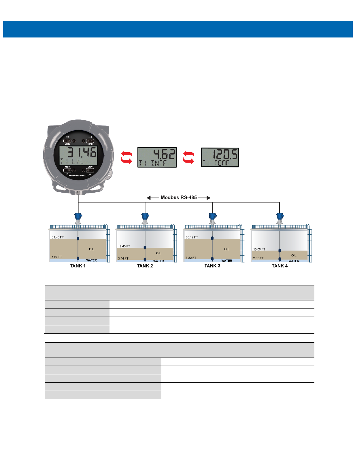
PD6730X Field-Mount Modbus Scanners
Address (Slave ID)
001
002
003
004
Baud Rate
4800 bps
4800 bps
4800 bps
4800 bps
Parity
None 1
None 1
None 1
None 1
Byte Order
1234 (big-endian: most significant digits register first)
Instruction Manual
Application Examples
The following applications show how the scanner can be configured for common applications.
Example 1: Master Polling Multivariable Level Transmitters
In this application we have a system consisting of four MTS LP-Series multivariable tank level gauges connected to a
PD6730-AX0-I-2 displaying product level, interface level, and average temperature. The PD6730X is setup for Master
mode, and it is polling the Modbus transmitters.
Note: As a tank level indicator displaying in units of feet, a PD6730-AX0-I-L could also be considered for this application. This would display feet and inches in the upper display and includes a tank level indicator.
Example 1 Level Transmitter Setup, Register Numbers, & Process Variables
Serial Communications
Parameters
Transmit Delay 50 ms 50 ms 50 ms 50 ms
Fixed Serial Data
Parameters
Level Register 30001, 30002
Interface Register 30003, 30004
Ave Temp Register 30017, 30018
Data Type Long Integer (2 registers), Binary, Signed
Tank 1
Transmitter
Tank 2
Transmitter
Tank 3
Transmitter
MTS LP-Series Transmitter Data
Tank 4
Transmitter
55
Page 56
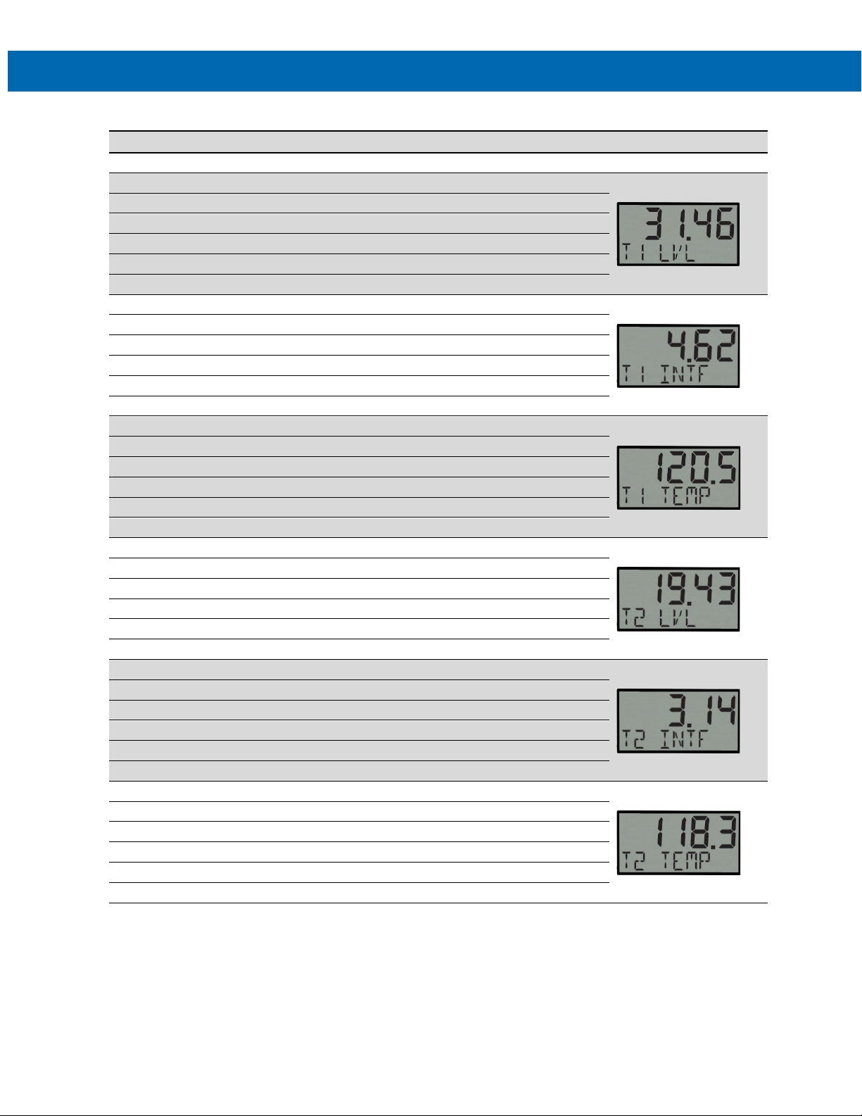
PD6730X Field-Mount Modbus Scanners
Parameter
PD6730X
Description/Comment
Display
Mode
Master
PV1
Enable
Register PV1
30001
Tank 1 Product Level
Byte Order
1234
Function Code
04
Data Type
Long integer Binary, Signed
PV3 Slave ID
1
Register PV3
30017
Tank 1 Average Temperature
PV4
Enable
Function Code
04
Byte Order
1234
PV5 Slave ID
2
Data Type
Long integer Binary, Signed
PV6
Enable
Register PV6
30017
Tank 2 Average Temperature
Byte Order
1234
The following table shows the PD6730X setup to work with the MTS LP-Series gauges.
PV1 Slave ID 1
Function Code 04
Instruction Manual
Data Type Long integer Binary, Signed
PV2 Enable
PV2 Slave ID 1
Register PV2 30003 Tank 1 Interface
Byte Order 1234
PV3 Enable
Function Code 04
Data Type Long integer Binary, Signed
Byte Order 1234
PV4 Slave ID 2
Register PV4 30001 Tank 2 Product Level
Data Type Long integer Binary, Signed
PV5 Enable
Function Code 04
Register PV5 30003 Tank 2 Interface
Byte Order 1234
PV6 Slave ID 2
Function Code 04
Data Type Long integer Binary, Signed
56
Page 57
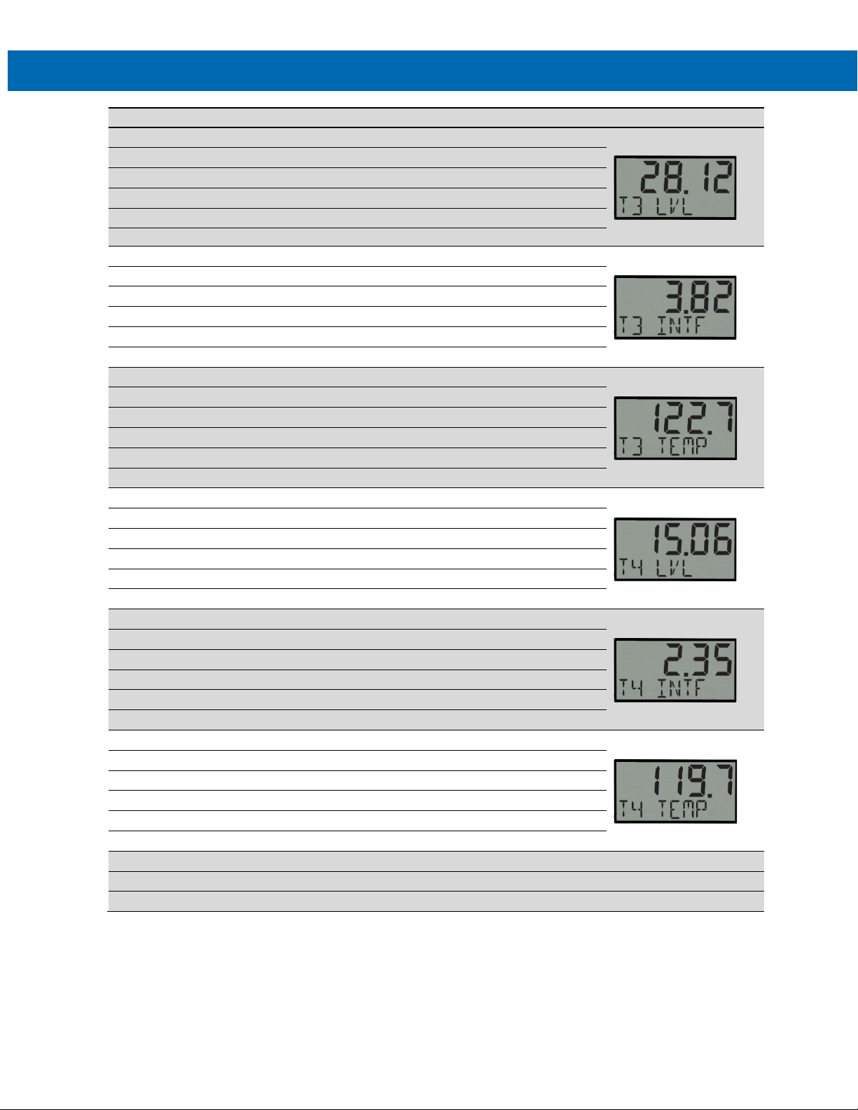
PD6730X Field-Mount Modbus Scanners
Parameter
PD6730X
Description/Comment
Display
Function Code
04
Byte Order
1234
PV8
Enable
Byte Order
1234
Data Type
Long integer Binary, Signed
Register PV10
30001
Tank 4 Product Level
Function Code
04
PV12 Slave ID
4
Poll Time
5.0 seconds
PV7 Enable
PV7 Slave ID 3
Register PV7 30001 Tank 3 Product Level
Data Type Long integer Binary, Signed
PV8 Slave ID 3
Function Code 04
Register PV8 30003 Tank 3 Interface
Data Type Long integer Binary, Signed
PV9 Enable
PV9 Slave ID 3
Function Code 04
Register PV9 30017 Tank 3 Average Temperature
Byte Order 1234
PV10 Enable
PV10 Slave ID 4
Function Code 04
Instruction Manual
Data Type Long integer Binary, Signed
Byte Order 1234
PV11 Enable
PV11 Slave ID 4
Register PV11 30003 Tank 4 Interface
Data Type Long integer Binary, Signed
Byte Order 1234
PV12 Enable
Function Code 04
Register PV12 30017 Tank 4 Average Temperature
Data Type Long integer Binary, Signed
Byte Order 1234
Timeout 0.3 seconds
Retries 3 Default Value
57
Page 58

PD6730X Field-Mount Modbus Scanners
Serial Communications
Transmit Time Delay
50 ms
Bottom Display
Tag & Units
Show Tag and Units for Each PV
Units
FEET
Input 2
12000
x1000 inch
Units
FEET
Input 2
12000
x1000 inch
Units
°F
Input 2
10000
x10,000 deg F
Parameter PD6730X Description/Comment
Scanner ID 246 Must be Unique on the Network
Baud 4800 bps Must Match All Network Devices
Parity None 1 Must Match All Network Devices
Setup
Display
Top Display PV Show Only PVs
PV Setup
PV 1 Identical for PV1, 4, 7, and 10
Format Top Display
Tag T1 LVL Indicates Tank 1 Level
Display Decimal Point 2
Scale Scaling for Level
Input 1 00000
Display 1 0.00
Instruction Manual
Display 2 10.00
PV 2 Identical for PV2, 5, 8, and 11
Format Top Display
Tag T1 INT Indicates Tank 1 Interface Registers
Display Decimal Point 2
Scale Scaling for Interface Registers
Input 1 00000
Display 1 0.00
Display 2 10.00
PV 3 Identical for PV3, 6, 9, and 12
Format Top Display
Tag T1TEMP T1 Indicates Tank 1 Average Temperature
Display Decimal Point 1
Scale Scaling for Temperature Registers
Input 1 00000
Display 1 0.0
Display 2 10.0
Feet
Feet
Deg F
58
Page 59
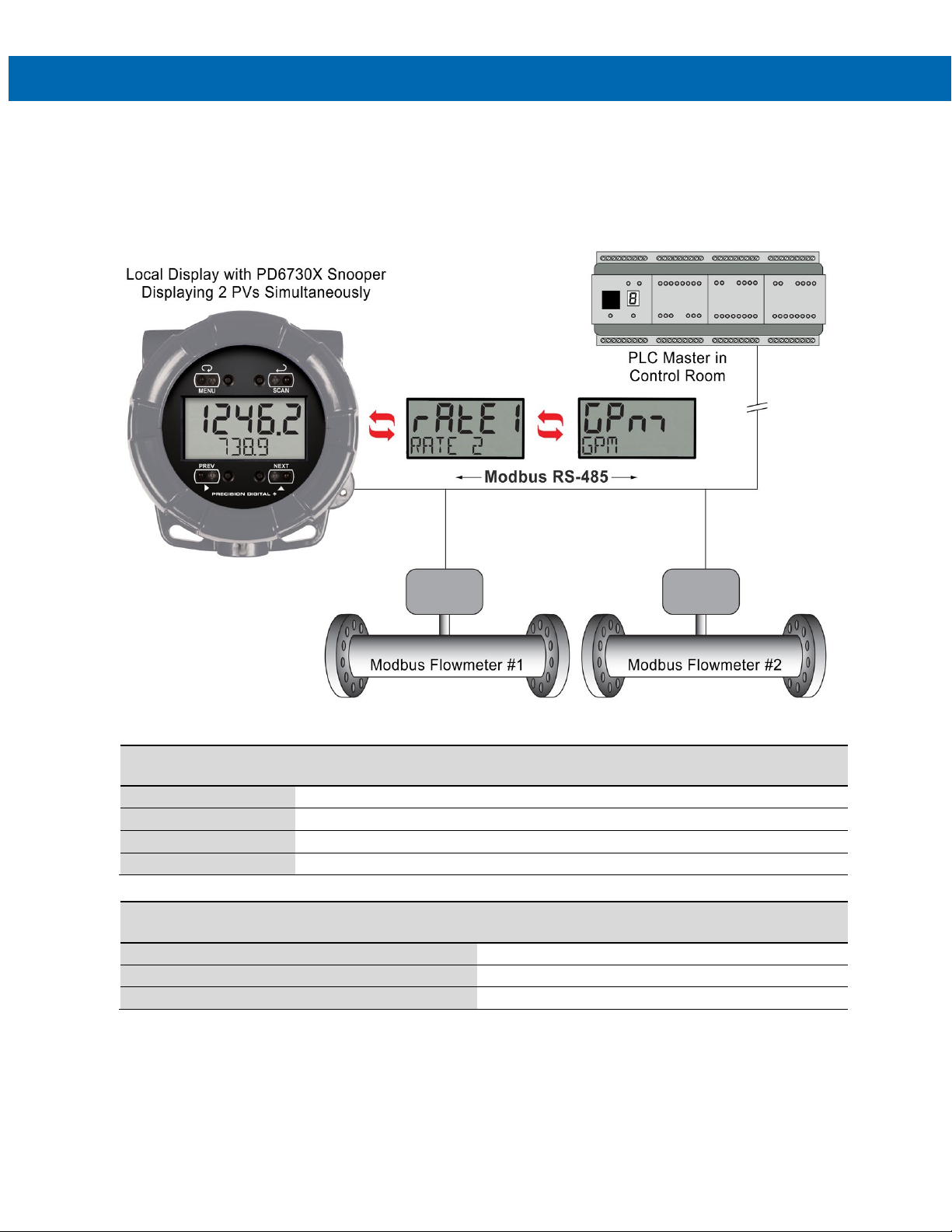
PD6730X Field-Mount Modbus Scanners
Address (Slave ID)
100
200
N/A
Baud Rate
4800 bps
4800 bps
4800 bps
Parameters
Flow Data Register
40001, 40002
Instruction Manual
Example 2: Snooper Displaying Flow Rate from Modbus Flowmeters
In this application we have a system consisting of two Modbus enabled flowmeters connected to a SCADA system
operated out of a control room. A Modbus PLC polls the data out of the flowmeters. A PD6730-AX0-I-2 has been
added to the system as a Modbus Snooper, to provide the operators an easy to read field display near the flow lines.
The scanner displays one flow rate on the top display, and one on the bottom display. Each has an alternating tag
and units for clear identification.
Example 2: Flow Meter & PLC Setup, Register Numbers, & Process Variables
Serial Communications
Parameters
Transmit Delay 50 ms 50 ms 50 ms
Parity None, 1 Stop Bit None, 1 Stop Bit None, 1 Stop Bit
Flow Transmitter 1 Flow Transmitter 2 Control Room PLC
Fixed Serial Data
Data Type Long Integer (2 registers), Binary, Signed
Byte Order 1234 (big-endian: most significant digits register first)
Modbus Flow Meter Data
59
Page 60

PD6730X Field-Mount Modbus Scanners
Parameter
PD6730X
Description/Comment
Mode
Snooper
PV1
Enable
PV1 Slave ID
100
Flow Meter 1 Address
Function Code
03
Register PV1
40001
Flow Meter 1 Rate
Data Type
Long integer Binary,
Byte Order
1234 PV2
Enable
PV2 Slave ID
200
Flow Mater 2 Address
Function Code
03 Register PV2
40001
Flow Meter 2 Rate
Data Type
Long integer Binary,
Byte Order
1234
Snooper Mode Response Time
2.0 seconds
Default Value
Serial Communications
Scanner ID
246
Must be Unique on the Network
Baud
4600 bps
Must Match All Network Devices
Transmit Time Delay
50 ms
Parity
None, 1 Stop Bit
Must Match All Network Devices
Setup
Display
Top Display
PV, Tag, & Units
Show PV, Tag, and Units for Each Top PV
Bottom Display
PV, Tag, & Units
Show PV, Tag, and Units for Each Bottom PV
PV Setup
PV 1
Format
Top Display
Show PV 1 (Flow Meter 1 Rate) on Bottom Display
Tag
RATE 1
Indicates Flow Meter 1 Rate
Units
GPM
Indicates Gallons Per Minute
Display Decimal Point
1 Scale
Scaling for Rate
Input 1
00000
Display 1
0.0 Input 2
50000
Display 2
5000.0
PV 2
Format
Bottom Display
Show PV 2 (Flow Meter 2 Rate) on Bottom Display
Tag
RATE 2
Indicates Flow Meter 2 Rate
Units
GPM
Indicates Gallons Per Minute
Display Decimal Point
1 Scale
Scaling for Rate
Input 1
00000
Display 1
0.0 Input 2
50000
Display 2
5000.0
The following table shows the PD6730X setup to work with two Modbus flowmeters.
Instruction Manual
60
Page 61
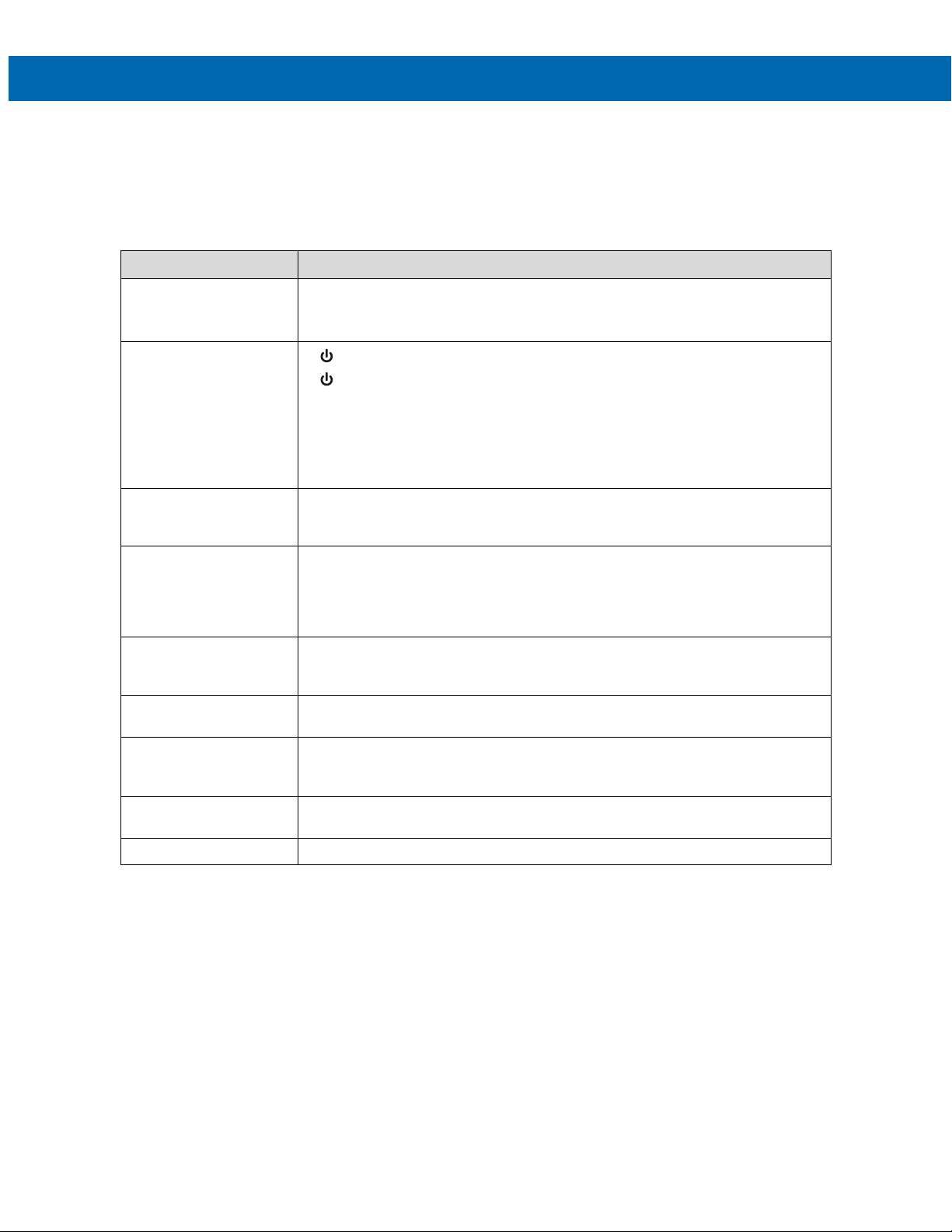
PD6730X Field-Mount Modbus Scanners
Instruction Manual
Troubleshooting
Due to the many features and functions of the scanner, it’s possible that the setup of the scanner does not agree with
what an operator expects to see. If the scanner is not working as expected, refer to the Diagnostics menu and consult
the recommendations described below.
Troubleshooting Tips
Symptom Check/Action
No display or faint display Check power connection.
Press and hold Menu key for 5 seconds to check for Standby mode. If “WAKEUP?” is
displayed, press the Enter key to awaken the scanner from Standby mode.
SafeTouch Buttons do
not respond
Scanner channel displays
NONE
Long time between
channel value updates
Scanner displays span
error message during
scaling
Scanner flashes
maximum display
If the display locks up or
the scanner does not
respond
Backlight does not
appear.
Other symptoms Call Technical Support for assistance.
If is displayed, hold Menu SafeTouch button to leave power save mode.
If is flashing, wait 60 seconds to leave mechanical pushbutton lockout mode.
If the cover was recently tightly secured, you may need to wait up to 2 minutes for
buttons to self-calibrate to the new cover position due to window reflection.
Verify THRU-GLASS BUTTONS switch on display module is in ON position.
Sunlight can interfere with the sensors. It is recommended to shield the window
while operating the buttons by standing so as to block direct sunlight.
Verify that the polling parameters (slave address, register, etc) are correct. If the
channel is a math channel CV, verify the chosen math function does not include
any NONE selections or un-programmed Modbus PVs.
Verify all channels are communicating. Errors, combined with long timeouts and
high allowable number of failures when polling Modbus devices, will combine to
significantly delay the polling speed. Reduce the number of allowable timeout
errors to check that communications are successful, and if there are errors, reduce
the timeout if possible.
Verify minimum input span requirements
Check slave device registers are valid. Check math channels are not exceeding
maximum possible display. Check input signal is within scaled range of 99999.
Perform hard reset by removing the display module or by removing DC power.
Backlight is intended for viewing assistance in dim lighting. It may not be noticeable
under good lighting conditions.
Note: Certain sequences of events can cause unexpected results. To solve these issues, it is best to start fresh from
factory defaults and map changes ahead of time, rather than at random.
61
Page 62
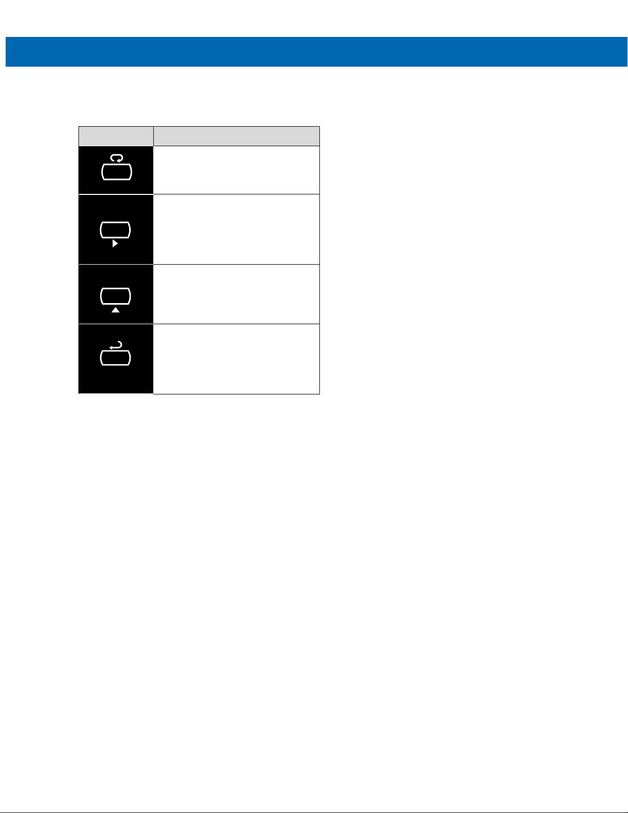
PD6730X Field-Mount Modbus Scanners
MENU
PREV
NEXT
SCAN
Quick User Interface Reference
Pushbutton Function
Go to Main menu. Back out one level
of programming.
Hold to enter Advanced menu.
Return to previous display variable.
Move to next digit or decimal point
position.
Return to previous same-level
programming menu.
Display next display variable.
Move to next selection or increment
digit.
Enter max/min display mode.
Pause/start automatic display
scanning.
Accept selection/value and move to
next selection.
Acknowledge Alarm.
Instruction Manual
62
Page 63

PD6730X Field-Mount Modbus Scanners
PRECISION DIGITAL CORPORATION
www.predig.com
Contact Precision Digital
Technical Support
Call: (800) 610-5239 or (508) 655-7300
Fax: (508) 655-8990
Email: [email protected]
Sales Support
Call: (800) 343-1001 or (508) 655-7300
Fax: (508) 655-8990
Instruction Manual
Email: [email protected]
Place Orders
Email: [email protected]
For the latest version of this manual please visit
www.predig.com
233 South Street • Hopkinton MA 01748 USA
Tel (800) 343-1001 • Fax (508) 655-8990
SFT092 & 93 Ver 1.200 & up
LIM6730X_D
08/21
 Loading...