

Page 1
LOW COST 3½ DIGIT LOOP-POWERED METERS
MODEL PD660 NEMA 4X
SPECIFICATIONS
Except where noted all specifications apply to operation at +25°C.
General
Input: 4-20 mA @ 24 VDC maximum
Display: 0.5" (12.7 mm) LCD, 3½ digits; 1999
Accuracy: ±0.1% FS ±1 count
Decimal Point: User selectable decimal point
Calibration: 2 step; non-interacting zero and span
Calibration Range: 4 mA input: -500 to +500;
20 mA input: between 20 and 2000 above 4 mA display
Maximum Voltage Drop: 1.5 VDC @ 20 mA;
3.5 VDC @ 20 mA with backlight option
Display Update Rate: 2.5/second
Loop-Powered Backlight Option: Factory installed only. Powered
directly from the 4-20 mA loop, no batteries required. The display
brightness will increase as the input signal current increases.
Connections: Removable screw terminals accept 12 to 22 AWG
Operating Temperature: -40 to 80°C
Storage Temperature: -40 to 80°C
Relative Humidity: 0 to 90% non-condensing
Approvals: The PD661-N-EX and PD661-B-EX are FM Approved
& CSA Certified as explosion-proof for Class I, Division 1,
Groups B, C, & D; dust-ignition proof for Class II, Division 1,
Groups E, F, & G; and Class III hazardous (classified) locations.
PD660 Enclosure: Impact-resistant ABS plastic body, color: gray, clear
polycarbonate cover with blue faceplate; NEMA 4X, IP67; ½" conduit
hole provided at base.
PD660 Weight: 9.3 oz (264 g)
PD661 Enclosure: Explosion-proof, cast aluminum with glass window,
0.3% max copper content, corrosion resistant polyester powder
coating, color: safety blue. NEMA 4X, 7, & 9, IP66; FM Approved
& CSA Certified: Class I, Division 1, Groups B, C, & D, Class II,
Groups E, F, & G, Class III hazardous
Two ½" NPT holes provided; mounts directly to conduit.
PD661 Weight: 3.1 lb (1.4 kg)
Warranty: 2 years parts & labor
Extended Warranty: 1 or 2 years, refer to Price List for details.
DISCLAIMER: The information contained in this document is subject to change
without notice. Precision Digital makes no representations or warranties with
respect to the contents hereof, and specifically disclaims any implied warranties
of merchantability or fitness for a particular purpose.
outdoor (Type 4X) locations.
• 4-20 mA Input
• 3½ Digit Display
• Loop-Powered Backlight Option
• Operates from -40 to 80°C
®
MODEL PD661 EXPLOSION-PROOF
ORDERING INFORMATION
Model Description
PD660- N* NEMA 4X Loop-Powered Meter
PD6 60- B NEMA 4X Loop-Powered Meter with Loop-Powered Backlight
PD661- N* Explosion- Proof Loop- Powered Meter
PD6 61- B Exp-Proof Loop-Powered Meter with Loop-Powered Backlight
PD661-N-EX FM Approved & CSA Cer tified Explosion-Proof Meter
PD661-B-EX FM & CSA Exp-Proof Meter with Loop- Powered Backlight
*Quick Shipment Program product, shipped within 2 working days.
Accessories
PDA6 604 Panel Mounting Kit for PD66 0 (No NEMA 4X Seal to Panel)
PDA6845 2" Pipe Mounting Kit for PD660
PDA6845- SS 2" Pipe Mounting Kit Stainless Steel for PD66 0
PDA-SSTAG Stainless Steel Tag
Services
PDN-CSETUP Custom Setup
PDN-CAL 2-Point Calibration
PDN-CERTCAL Certificate of Calibration
PDN-CERTCAL2 Certificate of Calibration with Data
PDN-LTCAL Lifetime Calibration with Annual Recert. - See Price List for Details
PDN-EXTWRNTY Extended Warranty Services - See Price List for Details
YOUR LOCAL DISTRIBUTOR IS:
PRECISION DIGITAL CORPORATION
www.predig.com
Page 2
LOW COST 3½ DIGIT LOOP-POWERED METERS
Ribbon Cable
SETUP
The only tools needed for calibration are a calibrated current
source, a flat head screwdriver, and a phillips head screwdriver.
Please note that the meter must be disassembled in order to
perform the setup functions.
Disassembly
The calibration controls are located behind the display faceplate.
To access these controls, you must first remove the enclosure
cover and faceplate by doing the following:
PD660: Loosen the four screws on the enclosure cover and remove.
Unscrew the two fasteners that hold the faceplate, then remove.
PD661: Turn the enclosure cover counterclockwise to remove.
Unscrew the two fasteners that hold the faceplate, then remove.
Connections
Field connections are made to the screw terminals located on
the Input Signal Board. To access these screw terminals it is
necessary to remove the Display Board from the Input Signal
Board. First, disconnect the ribbon cable connector from the
Display Board. Next, loosen the two screws located to the left and
right of the LCD that hold the Display Board in place. Finally,
remove the Display Board carefully to avoid contact with any
rough surfaces.
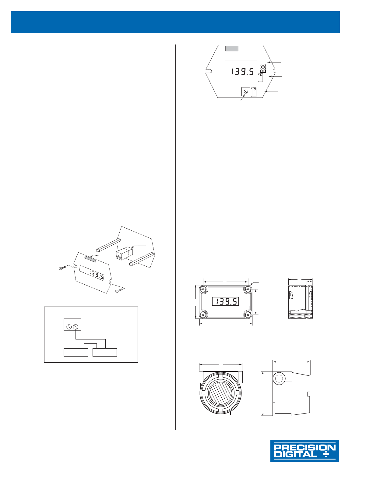
Connect a 4-20 mA input signal to terminal J5 located on the Input
Signal Board as shown below.
Screw
Terminal
Connector J5
Ribbon
Cable
Connector
Input Signal Board
Pollution Degree 2
Installation Category II
Note: When reassembling boards DO NOT over-tighten screws.
J5 Screw Terminal Connector
CAUTION - DISCONNECT FROM SUPPLY BEFORE OPENING. KEEP COVER TIGHT WHILE CIRCUITS ARE ALIVE.
CONDUIT SEALS MUST BE INSTALLED WITHIN 18" OF THE ENCLOSURE.
ATTENTION - OUVRIR LE CIRCUIT AVANT D’ENLEVEL LE COUVERCLE GARDER LE COUVERCLE BIEN FERME TANT QUE
LES CIRCUITS SONT SOUS TENSION. UN SCELLEMENT DOIT ETRE INSTALLE A MOINS DE 450 mm DU BOITIER.
Display Board
Wiring Diagram
+
-
SS
++
--
Loop Power
Supply
Signal Input Connections
4-20 mA
Transmitter
Balance Control (factory adjust only)
Calibration
The LO control (R11) is located below the display and the HI control
(R9) is located to the right of the display. Apply a 4 mA signal and
adjust the LO control to display the desired reading. Next, apply a
signal between 16 and 20 mA and adjust the HI control to display
the desired reading. Complete the calibration by making any
minor adjustments to the LO and HI controls.
MOUNTING
PD660
The PD660 can be wall mounted using the mounting holes beneath
the cover screws. It can be panel mounted with the addition of the
PDA6604 panel mount kit. It can also be pipe mounted by using the
PDA6845 or the PDA6845-SS 2" pipe mounting kit.
PD661
The PD661 has no provisions for wall mounting. Installation of
the unit is accomplished by using the two ½" NPT conduit holes
provided with ½" NPT fittings.
DIMENSIONS
PD660
A: 3.15 (80) C: 2.36 (60) E: 2.56 (65)
B: 4.33 (110) D: 3.54 (90) F: 0.79 (20)
PD661
A
Connector
R9
HI
Decimal Point
Jumper Array
HI
Calibration
Control
LO
Calibration
Control
E
C
Units: Inches (mm)
JP1
R10
BAL
D
B
R11
LO
Wall
Mounting
Holes
Beneath
Cover
Screws
C
A
F
Decimal Point Selection
Decimal point selection is accomplished using JP1 located behind
the faceplate to the right of the display. Leave jumper on one pin
only for a display of 1999 (default), place the jumper over both
bottom pins for a display of 199.9, middle for 19.99, top for 1.999
A: 4.5 (114) B: 4.75 (121) C: 3.75 (95)
PRECISION DIGITAL CORPORATION
19 Strathmore Road • Natick MA • 01760 • USA • Tel: (800) 343-1001 • Fax: (508) 655-8990
B
LIM660-661_E 11/05
www.predig.com
 Loading...