

Page 1
Model 930
Power Control System
Instruction Manual
Publication No. A105328-001 Rev A
December 2000
Another quality product from:
7128 Shady Oak Rd, Eden Prairie MN 55344
Phone: (952) 949-9009 Fax: (952) 949-9559
www.researchinc.com
Page 2

Dear Customer:
Thank you for purchasing a Model 930 ControlIR
TM
Power Control System. We believe
it is the finest system of its type and are confident you will think so too.
For technical assistance, training, replacement parts and assemblies, or any other
problems or questions, contact our Field Service specialists. They will do everything
they can to help you or will put you in touch with someone who can.
This instruction manual has been carefully prepared to make sure you get out of your
system all the capabilities we designed and built into it. To tell us how we could make
the system, our support of it, or this manual even more useful, we invite your to call our
product manager with your suggestions and recommendations.
Additional copies of this manual are available at a reasonable cost from our Customer
Service Department.
Once again, let us welcome you to the growing family of Research, Inc. customers. We
look forward to working with you in the future.
Sincerely,
Terry Nigon
President
Research Inc.
Page 3

Model 930 ControlIRTM Instruction Manual Contents
Section page
INTRODUCTION
General Description 1
Standard Features
Optional Features
1
2
SAFETY 3
INSTALLATION
Mounting the System
Wiring Connections
Power Wiring Connections 6
Line Connections 6
Load Connections 6
Control Connections 6
Cooling Flow On/Off Relay Output 6
Cooling Flow Switch Interlock 7
Heater Over-Temperature Thermo-switch Interlock 7
Remoter Interlock Switch 7
Heater Open Switch Interlock 7
Remote Setpoint Input 8
Temperature Control Option Connections (Option Codes TCT & TCP) 9
4
5
OPERATING INSTRUCTIONS
Controls and Indicators 10
Main Disconnect Switch 10
Heater ON/OFF Switch 10
Cooling ON/OFF Switch
Heater On Indicator 10
Cooling On Indicator
Heater Over Temperature Indicator
Lamp-Out, OCT / SCR Indicator 10
Remote/Local Setpoint Switch 11
Local Setpoint Potentiometer
Load Volts Indicator (Option Code VM) 11
Temperature Control Option
Setup Summary 12
Theory of Operation 12
Principles of SCR Power Control
Principles of Phase Angle Control 12
10
10
10
11
12
12
Page 4

Model 930 ControlIRTM Instruction Manual Contents
MAINTENANCE AND
TROUBLE SHOOTING
Routine Maintenance 16
Troubleshooting
Calibration
Power Controller 17
Panel Voltmeter Calibration 18
Temperature Controller Option 18
Line Voltage Re-Configuration 19
16
17
DIMENSIONS AND
SPECIFICATIONS
Specifications 20
Dimensions
Ordering Information 24
Ordering Example 24
Spare and Replacement Parts 25
22
Page 5
Model 930 ControlIRTM Instruction Manual Introduction
GENERAL
DESCRIPTION
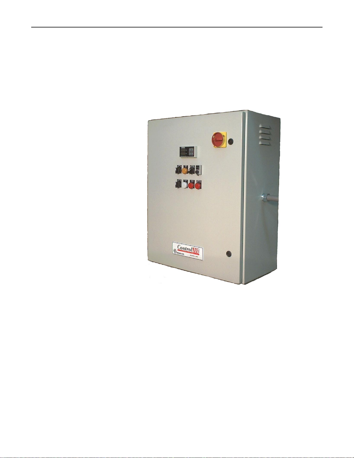
Figure 1-1 Model 930
Three Phase Power
Controller
STANDARD
FEATURES
Introduction
The Model 930 power control system is a complete power ‘solution’ featuring a
number of elements integrated into a single, ready-to-insta l l package . The M odel 9 30
is a three-phase power control system available in two configurations of 120 and 160
Amps at 480 Volts. These systems are ideally suited for many industrial power control
applications and have been specifically optimized for use with Research Inc. infrared
heating systems.
Standard features include:
• Local 10 turn potentiometer with digital dial for precise manual control of load
voltage.
• Remote control capability with a 0-5 VDC or 0-20 mA signal.
• Heater power switch with remote interlocks. The load voltage may be enabled or
disabled without turning off the main disconnect switch.
• Heater ON/OFF switch controls an AC contactor to remove power from the SCR
controller and the load.
• Cooling power switch to control air or water cooling flow.
• Cooling flow interlock contacts. Low cooling turns off the heater contactor.
• Heater open interlock contacts. A heater open condition turns off the heater
contactor.
• Heater over temperature contacts. Heater over temperature condition turns off the
heater contactor.
• Indicators lights for heater on, cooling on, heater over temperature, and SCR fault
condition.
Research, Inc. Page 1 of 25
Page 6

Model 930 ControlIRTM Instruction Manual Introduction
OPTIONAL
FEATURES
• Fail safe operation of the heater contactor. The contactor will not automatically re-
energize after a power failure, or an alarm condition that shuts down the heater.
• Programmable Logic Controller for operating and alarm logic control.
The following standard options are available:
Automatic Temperature Control Option
The automatic temperature control option allows the power level to be adjusted based
on an entered temperature setting for the process. The temperature controller uses PID
type control and is pre-wired for a ‘K’ type thermocouple (option code TCT) or a
4/20mA pyrometer signal (option code TCP).
Voltmeter Option
The true RMS load voltage is displayed with a digital meter. A true RMS voltage
transmitter is provided for isolation and operator safety.
Lamp-out Detection Option
The lamp out detection option is designed to detect a lamp failure or load loss when
using multiple infrared heaters or zones of lamps in a single heater. The SCR fault /
Lamp out indicator flashes during this condition.
Product Detect “PD” Option
The product detect option automatically adjusts the heater or lamp intensity between
run and idle states when a product is detected on the conveyor. A single turn idle
potentiometer is provided on the front panel. Idling the process saves energy and
equipment wear.
Research, Inc. Page 2 of 25
Page 7

Model 930 ControlIRTM Instruction Manual Operating Instructions
Safety
WARNING!
Hazardous voltages are present at the main disconnect switch and load terminals.
Setting the setpoint potentiometer or control signal to minimum does NOT eliminate
these hazardous voltages.
Always remove AC line voltage from the system before making contact with internal
assemblies, line or load wiring, or fuses. Also remove AC line voltage from the system
before making connections, equipment changes, or resistance measurements.
CAUTION!
Up to 480 volts AC is present within the power control solution system.
Do not make any wiring connections when power is applied.
Disconnect power before performing any maintenance or service to the system.
Use extreme caution when adjusting calibration potentiometers on modules when
power is applied.
Always use an isolated oscilloscope for checking waveforms.
Research, Inc. Page 3 of 25
Page 8
Model 930 ControlIRTM Instruction Manual Operating Instructions
MOUNTING THE
SYSTEM
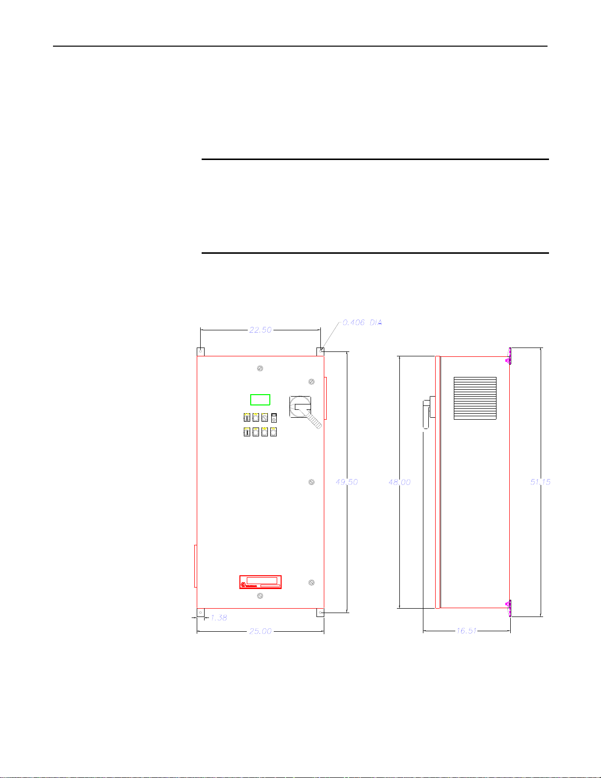
Figure 3-1 Wall Mounting
Dimensions
Installation
This section describes how to install and wire the Model 930 power control system.
The features and options mentioned here are identified in the model number found
inside the enclosure.
WARNING!
Hazardous voltages are present at the main disconnect switch and load terminals.
Setting the setpoint potentiometer or control signal to minimum does NOT eliminate
these hazardous voltages.
Always remove AC line voltage from the system before making contact with internal
assemblies, line or load wiring, or fuses. Also remove AC line voltage from the system
before making connections, equipment changes, or resistance measurements.
The Model 930 Power Control System may be mounted to a wall with the supplied
brackets, on a stand, or bench. The Model 930 must be mounted in a vertical position.
When mounting to a wall, the top of the enclosure should not be over 74 inches (1880
mm) above the floor.
The weight of the Model 930 varies slightly with the options installed. The maximum
weight of the system is ???.
Research, Inc. Page 4 of 25
Page 9
Model 930 ControlIRTM Instruction Manual Operating Instructions
WIRING
CONNECTIONS
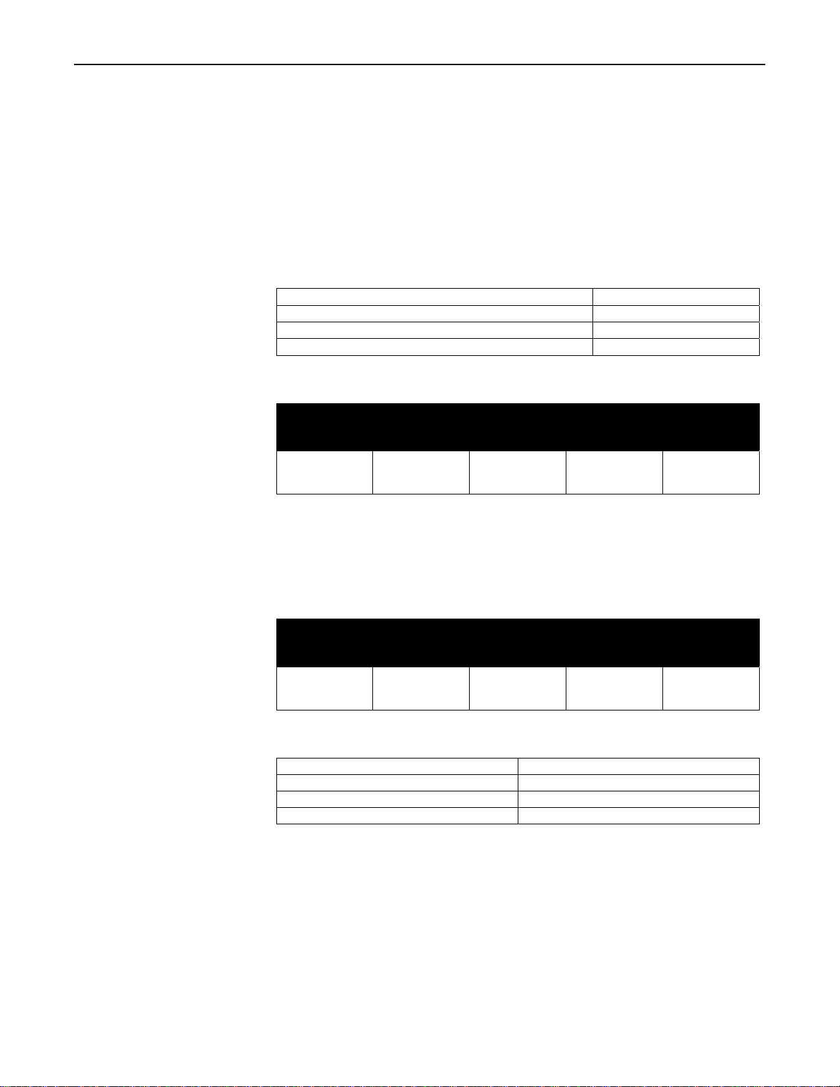
Table 3-1 Wiring Specifications
Conduit entry into the system should be made near the right side of the cabinet for
power wiring, near the center of the cabinet for load wiring, and near the left side for
low voltage control wiring. Assure that metal fragments are not allowed to fall into the
equipment while holes are made for conduit fittings.
We suggest a separate conduit entry should be made for low level DC control wiring if
used. This includes the remote setpoint input or thermocouple wire (temperature
control option).
Wire Ratings:
Wire Temperature Rating:
Line/Load Wiring Voltage Rati ng (2 4 0 VAC systems) 300 VAC Minimum
Line/Load Wiring Voltage Rati ng (4 8 0 VAC systems) 600 VAC Minimum
Control Wiring 300 VAC Minimum
75°C or Higher
Allowable Wire Sizes:
Current
Rating of
System
120 Amp
160 Amp
Line
Connections
#6-250 MCM
#6-250 MCM
Load
Connections
#6-250 MCM
#6-250 MCM
Ground
Connection
#4-1/0 AWG
#4-1/0 AWG
Control
Circuit
Connections
22-10 AWG
22-10 AWG
Recommended Minimum Wire Sizes:
NOTE:
Wire temperature and connector ampacity ratin gs are b as ed on NEC 31 0 -1 6 usin g
75
°
C copper wire derated for 50°C ambient environment.
Current
Rating of
System
120 Amp
160 Amp
Line
Connections
1 AWG
2/0 AWG
Load
Connections
6 AWG
4 AWG
Ground
Connection
6 AWG
6 AWG
Control
Circuit
Connections
16 AWG
16 AWG
Electrical Inputs:
Heater open interlock switch Contacts Rated for 120 VAC at 2.0 A
Cooling flow interlock switc h Contacts rated for 120 VAC at 100 mA
Heater over-temp. thermoswitch Contacts rated for 120 VAC at 100 mA
Remote interlock switch Contacts rated for 120 VAC at 100 mA
Research, Inc. Page 5 of 25
Page 10
Model 930 ControlIRTM Instruction Manual Operating Instructions
Power Wiring Connections
Line Connections
Load Connections
Figure 3-2
CONTROL
CONNECTIONS
Cooling Flow On/Off
Relay Output
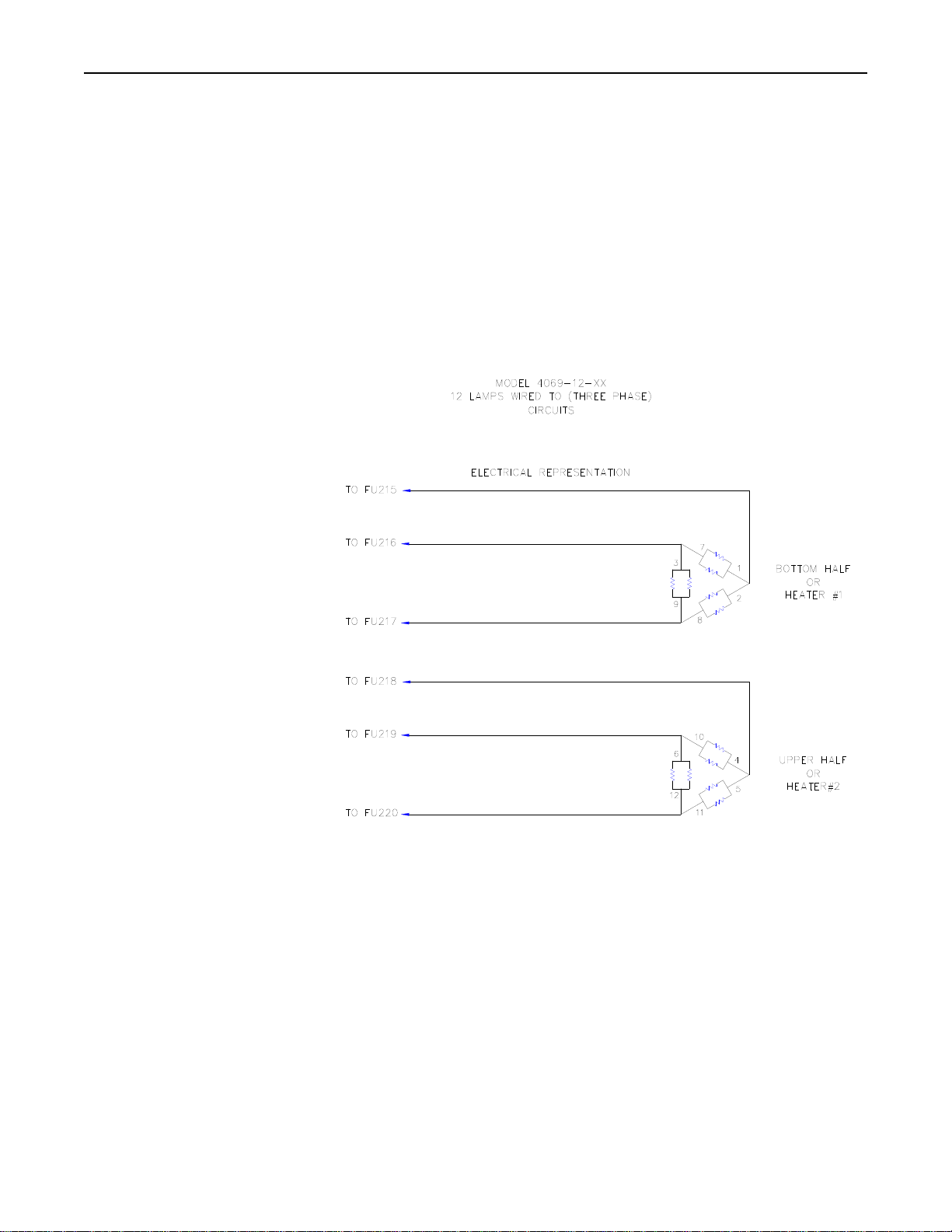
Referring to the wiring specification in Table 3-1, connect the external power lines to
the top of the disconnect switch.
The model 930 power control system has 2 (3-pole) load fuseblocks for distributing the
Three-phase power to your process. For the 120 Amp systems, do not exceed more
than 60 amps – 3 phase per fuseblock. For the 160 Amp systems, do not exceed more
than 80 amps – 3 phase per fuseblock. The heater load should be wired to evenly
distribute the number of individual lamps or heating elements to the 2 (three phase)
load circuits. It is suggested to balance the load circuits by having the same number
and size of lamps or heating elements per phase and per load circuit.
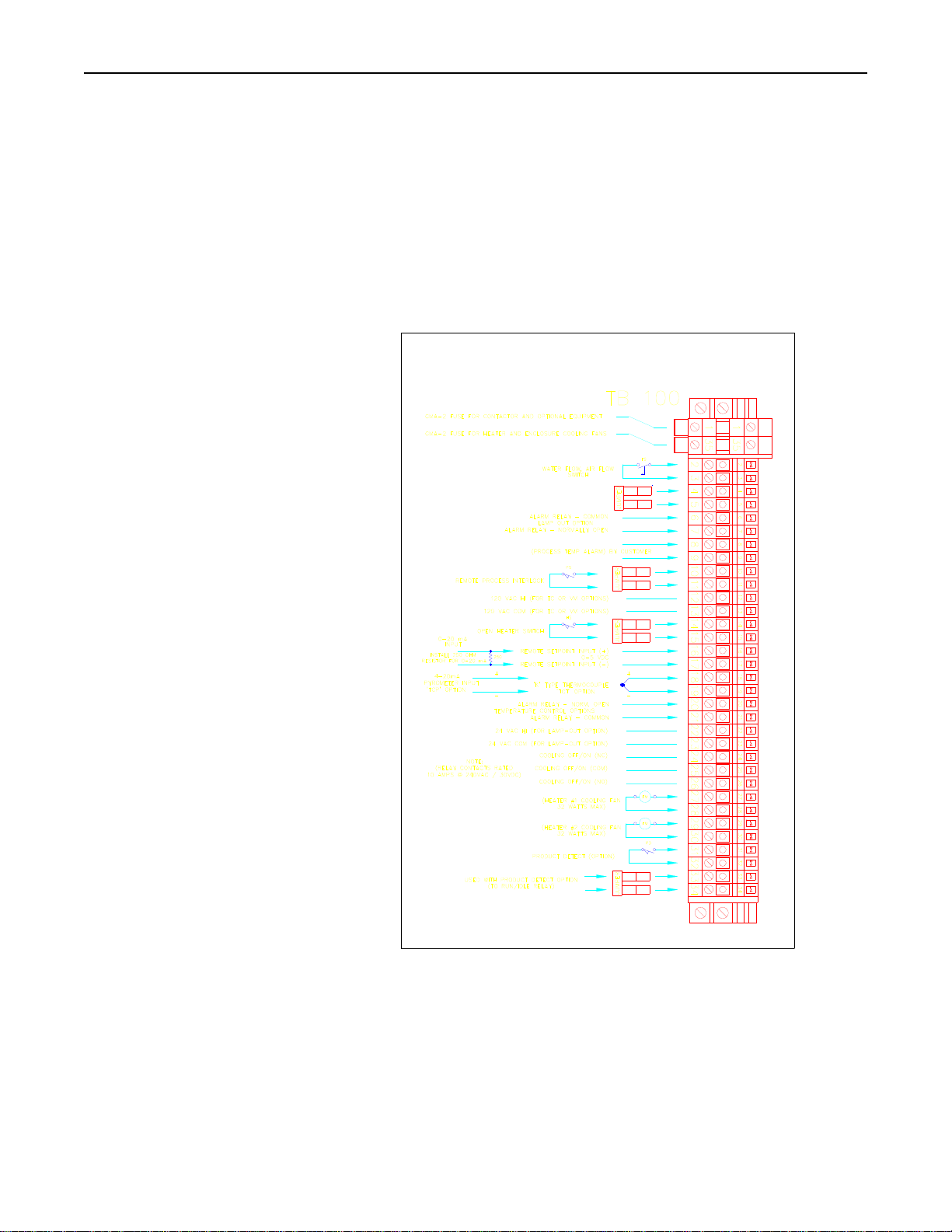
Refer to Figure 3-3 for connection of the following items.
This feature provides a normally closed and open (form C) dry contact relay output to
control cooling flow.
Connect the cooling solenoid /chiller/contactor circuit to TB-100 pins 24 (NC), 25
(COM), 26 (NO) as required.
Research, Inc. Page 6 of 25
Page 11

Model 930 ControlIRTM Instruction Manual Operating Instructions
Cooling Flow Switch
Interlock
Heater Over-Temperature
Thermo-switch Interlock
Remote Interlock Switch
Heater Open Switch
Interlock
This feature provides shutdown of the heater power in case of low or no cooling flow.
This is accomplished by opening the heater power controller contactor. The cooling
sensor may be a water flow or air flow switch. Use a switch with contacts that are open
during the fault condition.
Connect the flow switch to TB 100 pins 2 and 3. If both water and air cooling flow
switches are used in a system, wire the switches in series and then connect to the
system.
This feature provides shutdown of the heater power in case of a heater overtemperature.
This is accomplished by opening the heater power controller contactor. If a thermoswitch
is not included with your heater, use a thermo-switch with contacts that will open
during
the over-temperature condition. If this feature is desired or provided with the heater,
connect using the following procedure:
1. Remove the factory installed jumper at TB 100 pins 4 and 5.
2. Connect the thermo-switch to TB 100 pins 4 and 5.
3. If more than 1 thermo-switch is used, in a system, wire the switches in series and
then connect to the system.
This feature provides for remote process interlock shutdown of the heater power. This
is accomplished by opening the heater power controller contactor. With the interlock
open, the heater can not be turned on from the control system front panel. The switch
contacts must be open during the heater off condition. If this feature is desired, connect
using the following procedure:
1. Remove the factory installed jumper at TB 100 pins 10 and 11.
2. Connect the normally open contacts of the switch to TB 100 pins 10 and 11.
3. If more than 1 interlock switch is used in a system, wire the contacts in series and
then connect to the system.
This feature provides shutdown of the heater power if the heater is opened during
operation. This switch directly interlocks power to the heater contactor. If a heater
cavity
open switch is not included with your heater, use a switch with contacts that are open
when the heater is open. To implement feature, connect using the following procedure:
1. Remove the factory installed jumper at TB 100 pins 14 and 15.
2. Connect the normally open contacts of the switch to TB 100 pins 14 and 15.
3. If more than 1 heater open interlock switch is used in a system, wir e the contact s in
series and then connect to the system.
NOTE:
If a remote Emergency Stop switch is desired, wire the switch (push/pull type with
maintained contacts) in series with the heater open switch.
Research, Inc. Page 7 of 25
Page 12
Model 930 ControlIRTM Instruction Manual Operating Instructions
Remote Setpoint Input
Figure 3-3 Control Connections
This feature allows the power level of the system to be controlled from a remote
location or device. This is accomplished by apply i n g a 0-5 VDC o r 0- 20 mA signal
input from a remote source. This feature is not available when the ‘Temperature
Controller’ option is installed. If this feature is desired use the following procedure:
1. For a 0-5 VDC input, connect the source to TB 100 pins 16+ and 17-.
2. For a 0-20 mA input, connect the source to TB 100 pins 16+ and 17-. Also
install a 250 ohm resistor across terminals TB 100 16+ and 17-.
Research, Inc. Page 8 of 25
Page 13

Model 930 ControlIRTM Instruction Manual Operating Instructions
Temperature Control
Option Connections
(Option Codes TCT &
TCP)
Temperature control option ‘TCT’ is setup to use a ‘K’ type thermocouple for the
temperature input. Temperature control option ‘TCP’ is setup to use a pyrometer for
the temperature input. Alarm connections are provided if required for your process.
The alarm contacts are ‘dry’ type rated for a maximum of 3 Amps resistive at 240
VAC. If desired the process temperature alarm may be connected to the Front Paned
Over-Temp Alarm Indicator. Make connections as follows:
1. ‘TCT’ option: Use ‘K’ type extension wire from the thermocouple to the system
connections. Connect the ‘K’ thermocouple extension wire to TB 100 pins 18+
and 19-.
2. ‘TCP’ option: The pyrometer should source the 4-20 mA current through it’s
circuitry. If a ‘2 wire’ pyrometer is used, an external power supply must be used.
The model 935 does not source current for pyrometer operation. Connect the
4-20mA signal to TB 100 pins 18+ and 19-.
3. ‘TCT’ and ‘TCP’ options: To use the alarm output as an external process alarm.
Connect the device for the alarm output to TB100 pins 20 and 21.
If a remote alarm output is not used, the alarm may be connected to the front panel
over-temp alarm indicator. Connect TB 100 pin 20 to pin 8 and TB 100 pin 4 to
pin 11. The alarm indicator will flash while the temperature controller is in an
alarm condition.
Research, Inc. Page 9 of 25
Page 14

Model 930 ControlIRTM Instruction Manual Operating Instructions
CONTROLS AND
INDICATORS
Main Disconnect Switch
Heater ON/OFF Switch
Cooling ON/OFF Switch
Heater On Indicator
Cooling On Indicator
Heater Over Temperature
Indicator
Lamp-Out, OCT / SCR
Indicator
Operating Instructions
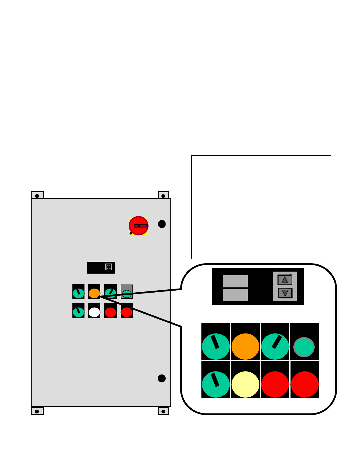
Figure 4-1 shows the location of the controls and indicators.
The main disconnect switch turn on and off the power control system. Note the
following:
Before turning on the disconnect switch, check the following:
1. The load is wired and ready for power to be applied to it.
2. All safety precautions are observed.
The Heater ON/OFF switch allows the operator to enable or disable the power going to
the load. This is accomplished by removing power from the AC contactor. This in
turn removes power from the SCR controller. The cooling on indicator must be on
before the heater power can be turned on.
The Cooling ON/OFF switch allows the operator to turn on or off the heater cooling.
• Indicator light on steady indicates power is applied to the heater power controller.
• Indicator light flashing indicates that the Remote Interlock is open and heater
power can not be applied.
• Indicator light on steady indicates adequate cooling flow.
• Indicator light flashing indicates that the cooling is in a one minute shutoff delay
cycle. The one minute delay cycle is activated any time that the heater power
contactor is opened, after the initial heater on cycle is activated.
• Indicator light on steady indicates a heater over temperature condition. A heater
over temperature condition will open the heater power contactor, removing power
from the heater.
• Indicator light flashing indicates a process over temperature alarm. This feature
is available only if the Temperature Control Option is installed. The indicator
will flash only as long as the process alarm exists.
• Indicator light on steady indicates a power controller over current (OCT) or a
power controller shorted scr (SCR) condition exists. The OCT / SCR alarm will
open the heater contactor, removing power from the load.
• Indicator light flashing indicates a lamp out condition. This feature is available
only if the lamp out (LL) option is installed. The alarm will remain on as long as
the lamp out condition exists.
Research, Inc. Page 10 of 25
Page 15
Model 930 ControlIRTM Instruction Manual Operating Instructions
Remote/Local Setpoint
Switch
Local Setpoint
Potentiometer
Load Volts Indicator
(Option Code VM)
Figure 4-1 Controls and
Indicators
2
The remote/local setpoint switch allows the operator to select the source for the power
level setting to the load, lamps, or heaters. The selections include:
1. LOCAL: The power level is adjusted using the digital 10-Turn ‘LOCAL
SETPOINT’ potentiometer.
2. REMOTE: The power level is controlled from a remote location or device or the
power level is controlled by the temperature controller if the TCT/TCP
temperature option is installed. The operator will enter a desired temperature
setpoint for the process. The power level is adjusted based on the feedback from
the temperature sensor connected to the process.
The power level is adjusted using the digital 10-Turn ‘LOCAL SETPOINT’
potentiometer when the ‘Setpoint’ switch is in the ‘Local’ position.
This option provides indication of the ‘True RMS’ load voltage.
1. Disconnect Switch
2. Optional Temperature Controller or
Optional Voltmeter
3. Heater On / Off Switch
4. Heater On Indicator
5. Remote / Local Setpoint Switch
1
6. Local Setpoint Potentiometer
7. Cooling On / Off Switch
8. Cooling On Indicator
9. Heater Over-Temperature Indicator
10. Over Current / Shorted SCR Indicator
and Optional Lamp Out Indicator
070
070
PV
SV
3 4 5 6
Heater
Off On
Cooling
Off On
Heater
On
Cooling
On
Setpoint
Rem Loc
Heater
Overtemp
Local
000
Lamp Out
OCT SCR
7 8 9 10
Research, Inc. Page 11 of 25
Page 16
Model 930 ControlIRTM Instruction Manual Operating Instructions
TEMPERATURE
CONTROL OPTION
Setup Summary
Table 4-1 Temperature
Controller
Configuration
THEORY OF
OPERATION
Principles of SCR Power
Control
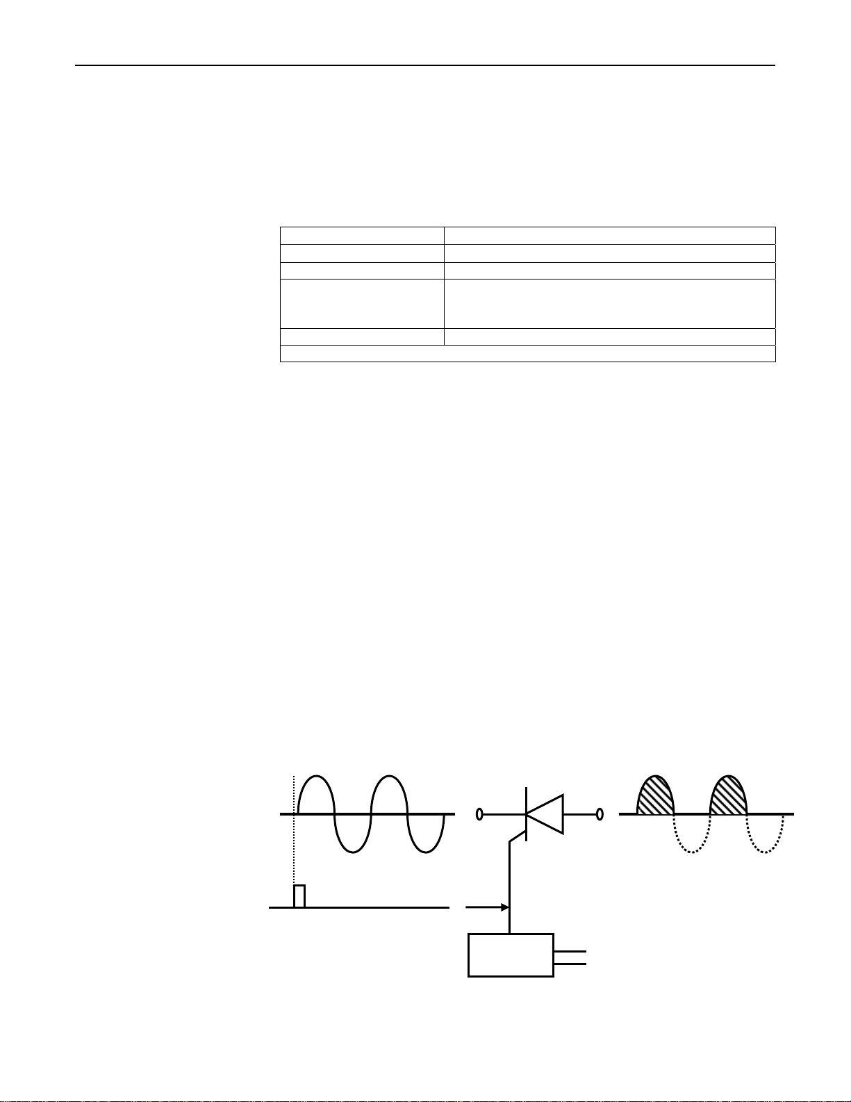
Figure 4-2 Conduction of one
SCR when turned on
at the beginning of a
half-cycle
This section contains temperature controller configuration information for your system.
Refer to the Model XT19 installation and instruction manual for operating the
temperature controller.
Table 4-1 displays factory configurations made for your system:
Sensor Input (TCT option)
Sensor Input (TCP option)
Control Type: PID (proportional, integral & derivative)
AL 1 (alarm 1):
Control Output: 0-20 milliamps
This alarm may be re-configured as necessary for your process
SCR type power controllers control power by regulating when silicon controlled
rectifiers (SCRs) conduct AC line current to the load.
A SCR is a solid-state, electronic switching device that turns on (fires) very quickly
when a low-level “gating” signal is applied to its gate electrode. The timing of the
gating signal, and therefore the length of time the SCR condu c ts, is de termined by the
controller’s firing circuitry in response to a control signal. The greater the percentage
of time the SCR is on, the greater the average power it allows to pass through to the
load.
The Model 910 uses a random-fire solid state relay within its SCR poser controller.
This relay is a package consisting of 2 SCRs and a gate drive circuit.
During the positive half-cycle of the AC line voltage the SCR’s anode is positive with
respect to its cathode, so during that half-cycle the SCR will begin to conduct
whenever a gating signal is applied to its gate electrode (see figure 4-2). Once turned
on, an SCR will continue to conduct until its anode-to-cathode voltage drops to zero, so
the SCR continues to conduct until the end of the half-cycle.
‘K’ type thermocouple scaled 0-2500°F
4-20mA signal scaled 0-2500°F
Full scale high, non-latching, set for 2000°F
(This alarm will trip a relay connected to TB100 pins 13
and 14)
CATHODE ANODE
INPUT LINE VOLTAGE
GATING SIGNAL
CIRCUITRY
Research, Inc. Page 12 of 25
GATE
OUTPUT LINE VOLTAGE
FIRING
CONTROL SIGNAL
Page 17
Model 930 ControlIRTM Instruction Manual Operating Instructions
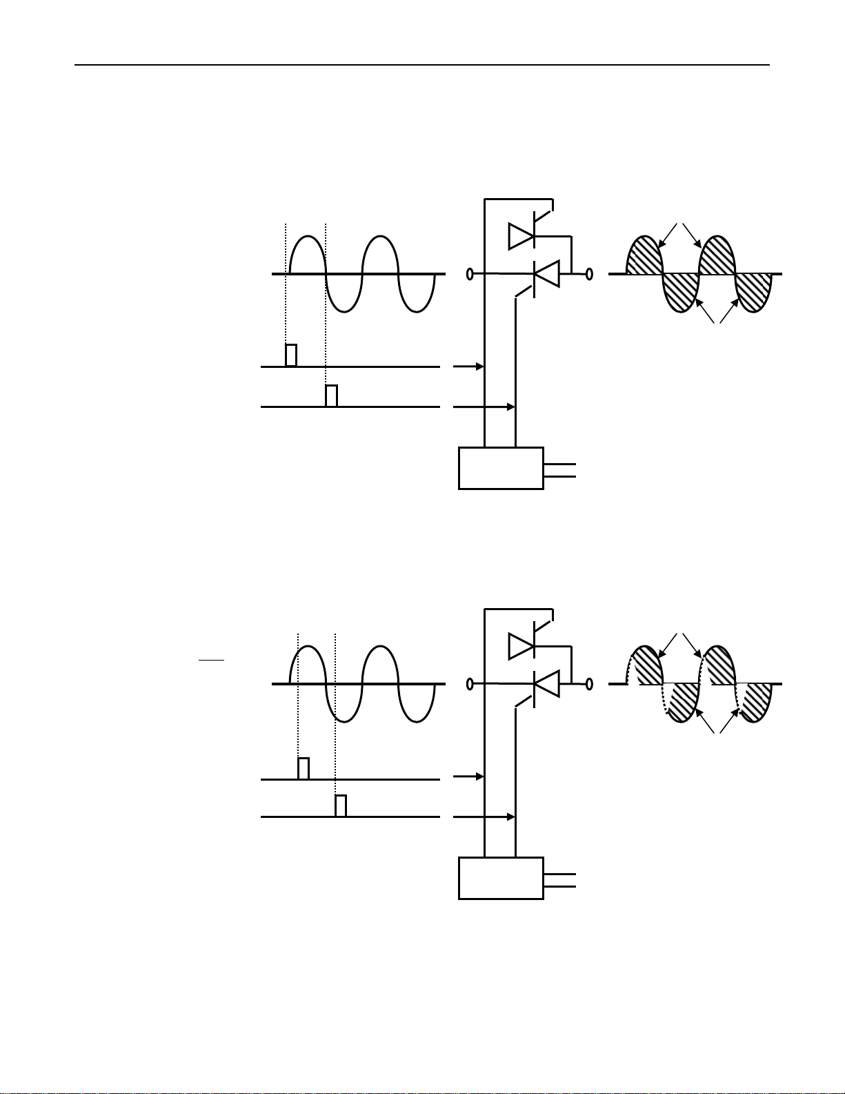
Figure 4-3 Conduction of two
SCRs connected in
reverse parallel when
turned on at the
beginning of
half-cycles
Principles of Phase Angle
Control
Figure 4-4 Conduction of two
SCRs connected in
reverse parallel when
turned on after
beginning of the
half-cycles
the
Because an SCR is a type of diode, it can conduct only during every other half-cycle of
the applied voltage. Therefore, SCRs used to control AC power are usually installed in
pairs, connected in reverse-parallel, as shown in figure 4-3. One of the SCRs then can
be fired during the positive half-cycle and the other can be fired during the negative
half-cycle.
In phase angle controllers, the SCRs conduct during all or part of every half-cycle.
When delivering full power, the SCRs start conducting at the beginnings of the AC
half-cycles. When delivering less than maximum power, the gating signal is de-layed
so the SCRs start conducting some time later than the beginnings of the half-cycles.
Operation of a phase angle controller at partial output is depicted in figure 4-4.
INPUT LINE VOLTAGE
GATING SIGNAL
GATING SIGNAL
INPUT LINE VOLTAGE
GATING SIGNAL
GATING SIGNAL
FIRING
CIRCUITRY
FIRING
CIRCUITRY
SCR 1
SCR 1
SCR 2
SCR 2
OUTPUT LINE VOLTAGE
CONTROL SIGNAL
SCR 1
SCR 1
SCR 2
SCR 2
OUTPUT LINE VOLTAGE
CONTROL SIGNAL
Research, Inc. Page 13 of 25
Page 18
Model 930 ControlIRTM Instruction Manual Operating Instructions
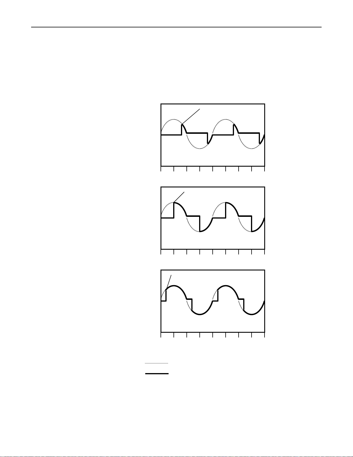
Figure 4-5 Phase angle power
control
The average power a phase angle controller de livers to its load is determined by the
number of electrical degrees by which the gating signal that turns on the SCRs is
delayed past the beginnings of the half-cycles. The later in each half-cycle the SCRs
fire, the less the time the SCRs conduct during each half-cycle and, therefore, the less
power is delivered to the load (see figure 4-5). The 0–5 VDC control signal received
by the phase angle firing-circuit determines the amount by which the gating signal is
delayed.
135° PHASE ANGLE
LOW POWER
OUTPUT
360° 270° 180° 90° 360° 270° 180° 90° 0°
90° PHASE ANGLE
MEDIUM POWER
OUTPUT
HIGH POWER
OUTPUT
360° 270° 180° 90° 360° 270° 180° 90° 0°
45° PHASE ANGLE
360° 270° 180° 90° 360° 270° 180° 90° 0°
AC PHASE ANGLE
AC LINE VOLTAGE
OUTPUT VOLTAGE TO LOAD
Research, Inc. Page 14 of 25
Page 19

Model 930 ControlIRTM Instruction Manual Operating Instructions
The output voltage of a phase angle controller does not change linearly with respect to
the number of degrees the SCR conduction phase angle changes. Therefore, the SCR
controllers have a built-in load feedback circuit to linearize the relationship between
the control signal and the voltage output. The feedback circuit also adjusts the power
controller output to compensate for changes in line voltage and load impedance (this is
called “line and load regulation”).
Phase angle power control offers a number of attractive features. Because the power
controller output level is adjusted by varying the SCR on time within each AC halfcycle, the controller’s output is quite constant, rather than being divided into multiplecycle periods of on time and off time. In addition, a variety of feedback and output
indication (metering) circuits can easily be incorporated into the controller.
Research, Inc. Page 15 of 25
Page 20

Model 930 ControlIRTM Instruction Manual Maintenance and Trouble Shooting
ROUTINE
MAINTENANCE
TROUBLESHOOTING
Maintenance and
Trouble Shooting
The following bi-monthly routine maintenance is suggested:
1. Remove power connection to the system. Lock out power if possible. Carefully
vacuum any dust or dirt collecting within the enclosure. Use caution to not disturb
the wiring. Service more often in dust locations.
2. Clean the outside of the enclosure with glass cleaner and a soft cotton cloth as
necessary.
Symptom Action
Heater Contactor will not
energize.
No output to load, heaters
or lamps. Setpoint switch
is in LOCAL mode.
1. Verify line voltage is applied to the main disconnect
switch.
2. Verify remote heater open, remote process interlocks
or water flow switches (if used) are closed.
3. If not using remote heater enable, heater open
interlocks or water flow switches, verify the 2 pin
jumpers are installed between TB 100 pins 2 to 3, 10
to 11 and 14 to 15.
4. Check fuses FU 1050, FU 1051, FU 107, FU 108 and
TB 100 pin 1.
1. Verify the ‘Heater On’ indicator is illuminated.
2. Verify a 0-5 VDC signal is present on pins 13 and 14
of the power controller connector. This voltage is
proportional to the setting of the local Setpoint
potentiometer or the idle potentiometer (product
detect option) if product is not detected.
3. If the over current light on the controller is
illuminated, check the load wiring, lamp or heater
connections for short circuits.
4. If the shorted SCR light is lit on the controller, refer
to the power controller manual regarding repairs.
5. If the COMMAND led on the power controller is not
lit and a control signal is greater than 10 percent is
applied, refer to the power controller manual
regarding repairs.
Research, Inc. Page 16 of 25
Page 21

Model 930 ControlIRTM Instruction Manual Maintenance and Trouble Shooting
CALIBRATION
Power Controller
Symptom Action
No output to load, heaters
or lamps. Setpoint switch
is in REMOTE. Operation O.K. with Setpoint
switch in LOCAL (if not
see above).
Full voltage cannot be
obtained.
Load voltage will not go
to zero.
Generally components of the power control system hold their calibration very well
over a long period of time. Usually verification of calibration is all that is necessary.
We suggest verification or calibration be performed on a yearly basis. Calibration
should be performed by qualified personnel as danger ou s v olt ages a re pre s ent.
Refer to the power controller manual for specific calibration instructions. Calibrate
using step 1, 2 or 3 below (use whichever is used most often):
1. When LOCAL setpoint mode is selected, the local setpoint potentiometer is used
as the source for the input. Adjust the zero and span potentiometers on the power
controller. The SPAN potentiometer is adjusted for 90 percent or rated line
voltage for 900 dial divisions of the local setpoint pot. The ZERO potentiometer is
adjusted for 0 Volts output when the local setpoint is set to 000 dial divisions.
1. Verify the polarity of the remote input. TB 100 pin
16 is positive, and 17 is negative.
2. Units with Temperature control option: Place
temperature controller in manual mode with 50
percent output. Verify 2.5VDC at TB 100 pins 16
and 17. Refer to the temperature controller manual
regarding repairs.
1. Verify the load, lamps, or heaters are not drawing
current at full capacity of the system. Rotate the
current limit pot on the power controller 1 turn
counterclockwise. If the load current decreases, the
current limit is controlling the output.
2. Verify the line voltage. Load voltage maximum is
approximately 98 percent of the line voltage.
3. Test in LOCAL setpoint mode. Set the ‘Local
Setpoint’ potentiometer to 900. The voltage should
be 216 (240 volt line), or 432 (480 volt line). Adjust
the RUN SPAN potentiometer of the power
controller as necessary.
4. Faulty power controller SCR or control circuit. Refer
to the power controller manual regarding repairs.
1. Verify the load voltage will go to zero with the SCR
switch set to DISABLED. If it does not, refer to the
power controller manual regarding repairs.
2. If the shorted SCR indicator of the power controller
is on, an SCR has failed.
3. Units with the Product Detect option: Normal
operation of the idle circuit. The idle potentiometer
maintains the voltage at idle.
4. Units with the Conveyor / Web speed option:
Normal operation. The minimum idle potentiometer
may be adjusted to lower the load voltage to zero if
the web is stopped.
Research, Inc. Page 17 of 25
Page 22

Model 930 ControlIRTM Instruction Manual Maintenance and Trouble Shooting
Panel Voltmeter
Calibration
Temperature Controller
Option
2. Voltmeter Option or No Options: When REMOTE setpoint mode is selected, use
a 0-5 VDC source for an input. Adjust the zero and span potentiometers on the
power controller. The SPAN potentiometer is adjusted for 90 percent of rated line
voltage for 4.5 VDC input. The ZERO potentiometer is adjusted for 0 Volts
output when the local setpoint is set to 000 dial divisions.
3. Temperature Controller option only : Whe n AUTO setpoint mode is selected, the
temperature controller is used as the source for the input. Adjust the zero and span
potentiometers on the power controller. The SPAN potentiometer is adjusted for
90 percent of rated line voltage for 90 percent output of the temperature controller.
The ZERO potentiometer is adjusted for 0 volts output when the temperature
controller is set to 0 percent.
The front panel load voltmeter is calibrated to match as closely as possible the true
RMS voltage measured at the load terminals.
1. Connect a true RMS DVM to load 1 and load 2.
2. Connect another DVM across pins 1(+) and 2(-) of the EXT 200 RMS voltage
transmitter.
3. Turn the HEATER switch to OFF. Measure the voltage of EXT 200 pins 1(+) and
2(-) to be 0.0 VDC +/- 10 millivolts. Adjust the EXT 200 zero potentiometer if
necessary.
4. Verify the panel voltmeter reads 0 volts. If necessary, carefully remove the front
cover of the meter and adjust the zero potentiometer for 000 +/- 1 reading.
5. Turn the Heater switch to ON. Adjust the LOCAL SETPOINT potentiometer for
the following load voltage based on the voltage your system is configured for:
480 VAC units: 450 VAC
240 VAC units: 225 VAC
6. Measure the voltage of EXT 200 pins 1(+) and 2(-) to be the following voltage +/-
10 millivolts:
480 VAC units: 3.750 VDC
240 VAC units: 1.875 VDC
7. Verify that the panel voltmeter reads the voltage as set in Step 5 above. If
necessary, carefully remove the front cover of the meter and adjust the span
potentiometer for a +/- 1 reading.
Refer to the temperature controller manual for calibration instructions.
Research, Inc. Page 18 of 25
Page 23
Model 930 ControlIRTM Instruction Manual Maintenance and Trouble Shooting
LINE VOLTAGE
RE-CONFIGURATION
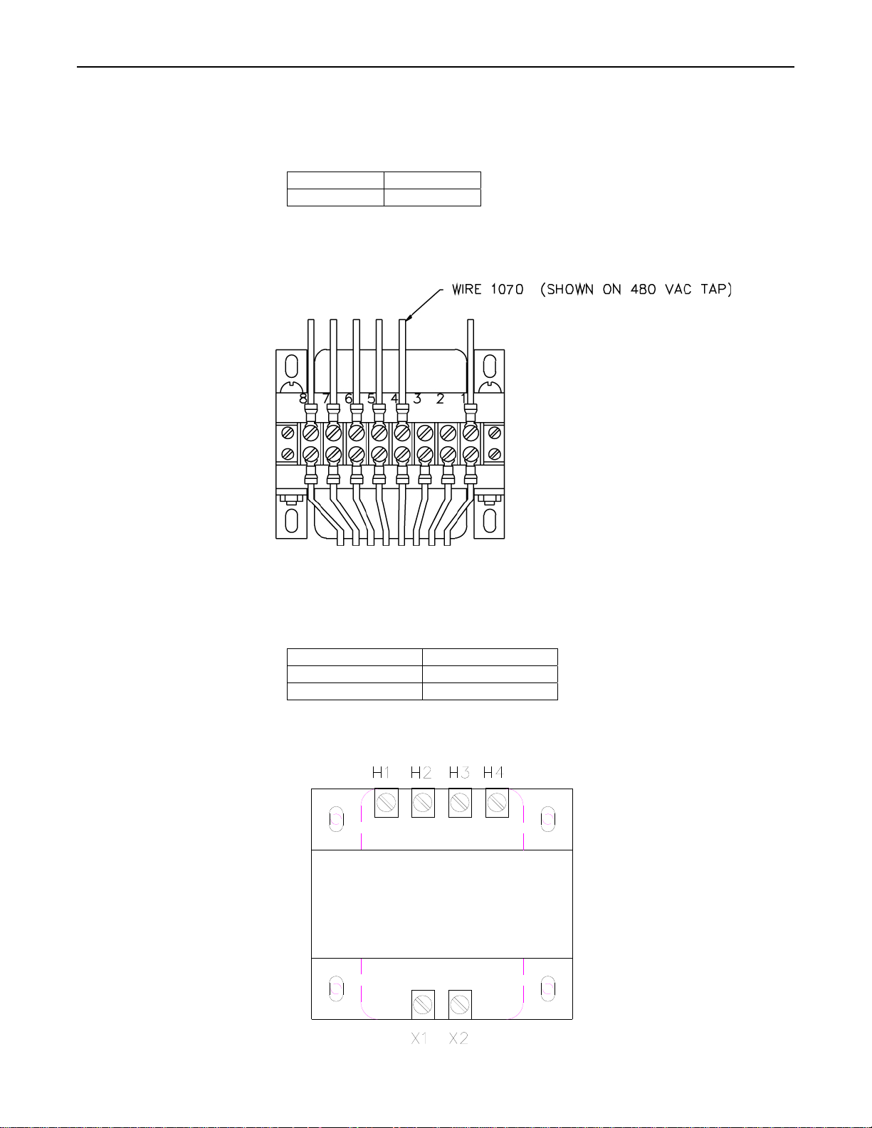
Figure 5-1 AC Voltage Tap
Figure 5-2 T200 Transform e r
The AC line voltage for the Model 930 Power Control System may be re-configured. On
transformer T100, a wire with wire number 1070 is connected to pins 3 or 4. Move this
wire to the pin corresponding to the desired line voltage.
Pin 3 240 VAC
Pin 4 480 VAC
See Figure 5-1 below.
On transformer T200, it is necessary to re-configure the primary wires per the
following (see Figure 5-2):
240VAC 480VAC
Jumper H1 to H3 Jumper H3 to H2
Jumper H2 to H4
Research, Inc. Page 19 of 25
Page 24
Model 930 ControlIRTM Instruction Manual Dimensions and Specifications
SPECIFICATIONS
Dimensions and
Specifications
Environmental Limits:
Operating Temperature 0-50 deg. C (32-122 deg. F)
Storage Temperature -40-70 deg. C (-10-158 deg. F)
Humidity 0-90 %, non-condensing
Clearance 4” (100mm) on right and left sides
Weight:
The system weight varies slightly with the options installed. The maximum weight of
the system is ??? pounds (??? kg).
Operating Voltage:
240 or 480-VAC +10%, -15% at 50 or 60 Hertz. Voltage set at factory per order.
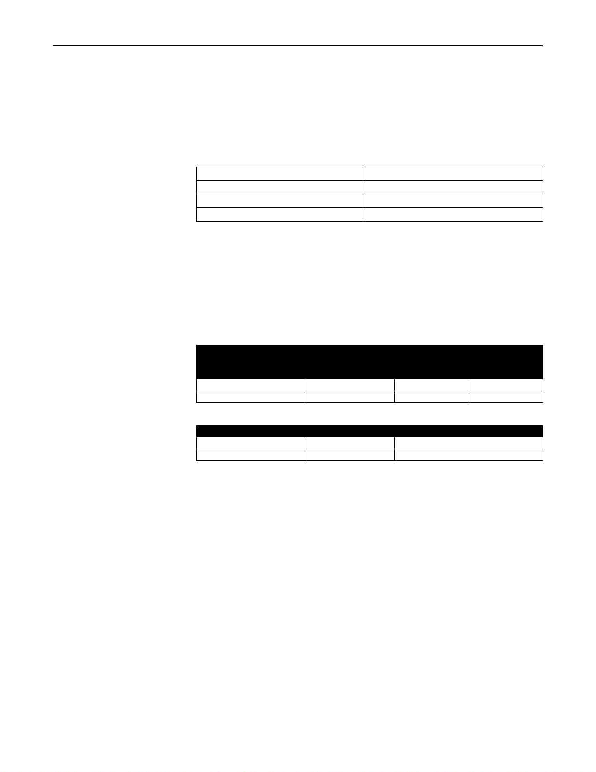
Operating Current and kW:
Current Rating of System
120 Amp 120 Amps 50 99.8
160 Amp 160 Amps 66.5 133
Line Fusing:
Current Rating of System Fuse Type Fuse Rating
120 Amp JJS-150 Class T 150 Amp 600 Volt
160 Amp JJS-200 Class T 200 Amp 600 Volt
Power Control:
Control Mode:
SCR phase-angle control of the voltage applied to a three phase load. True RMS
voltage feedback for load voltage regulation.
Control Range:
0-98% of supply voltage.
Output Linearity:
RMS load voltage varies linearly with control signal, within +/- 2 percent of span
over the entire range of control.
Continuous Current
Rating at 50°C
Maximum Power kW at
240 VAC 480 VAC
Research, Inc. Page 20 of 25
Page 25
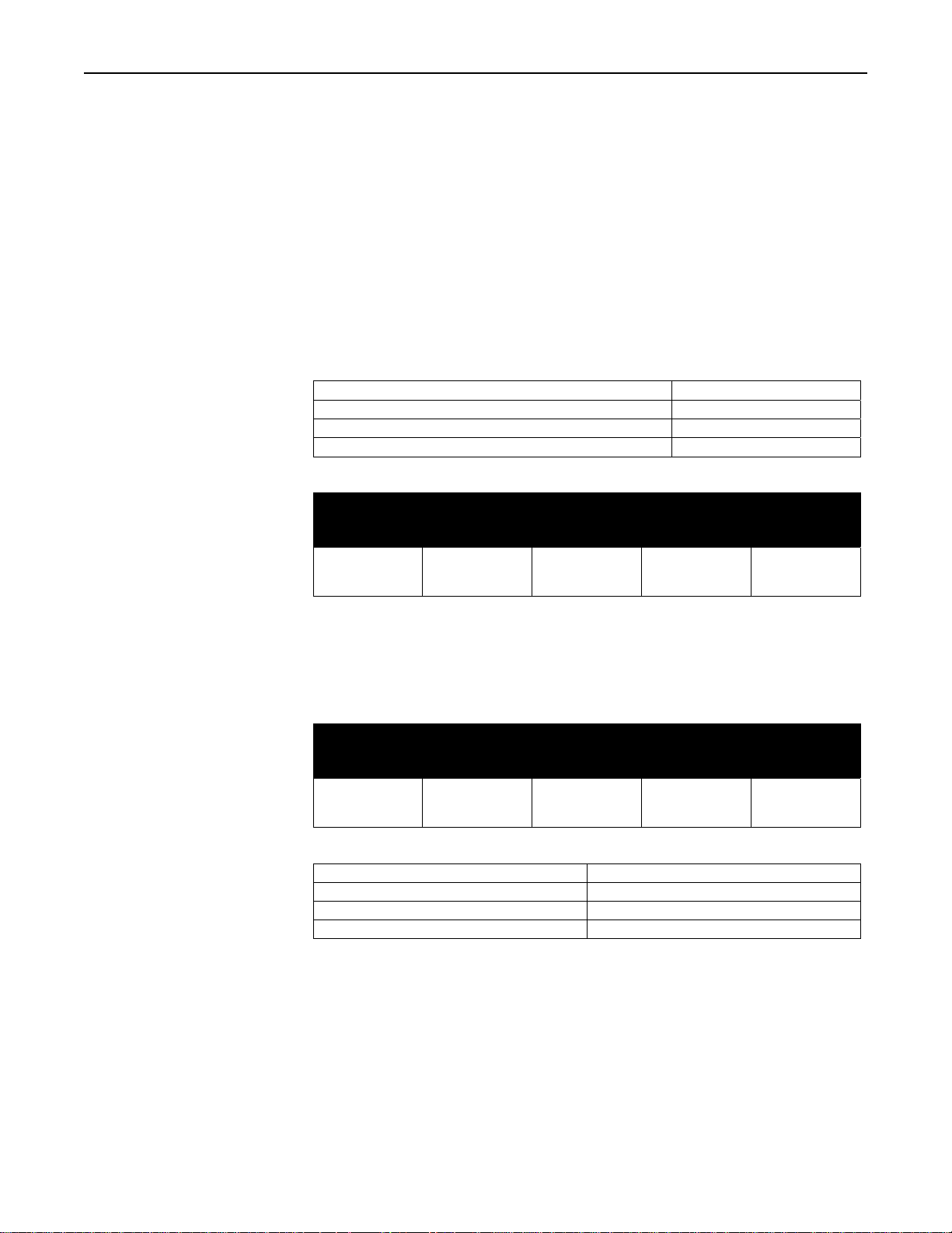
Model 930 ControlIRTM Instruction Manual Dimensions and Specifications
Wiring Specifications
Electrical Isolation:
Heat sink to supply and load voltage: 2500 Volts peak.
Command signal to supply and load voltage: 1400 Volts peak.
Slew Rate:
200 ms. Slew rate is the time required for the load voltage to change 63% of the
value represented by the command signal. The current limiting action will affect
the slew rate if the load current is greater than the current rating of the SCRs.
Wire Ratings:
Wire Temperature Rating:
Line/Load Wiring Voltage Rati ng (2 4 0 VAC systems) 300 VAC Minimum
Line/Load Wiring Voltage Rati ng (4 8 0 VAC systems) 600 VAC Minimum
Control Wiring 300 VAC Minimum
Allowable Wire Sizes:
Current
Rating of
System
120 Amp
160 Amp
Recommended Minimum Wire Sizes:
NOTE:
Wire temperature and connector ampacity ratings are based on NEC table 310-16
using 75
Electrical Inputs:
°
C copper wire derated for 50°C ambient environment.
Current
Rating of
System
120 Amp
160 Amp
Heater open interlock switch Contacts Rated for 120 VAC at 2.0 A
Cooling flow interlock switc h Contacts rated for 120 VAC at 100 mA
Heater over-temp. thermo-switch Contacts rated for 120 VAC at 100 mA
Remote interlock switch Contacts rated for 120 VAC at 100 mA
Line
Connections
#6-250 MCM
#6-250 MCM
Line
Connections
1 AWG
2/0 AWG
Load
Connections
#6-250 MCM
#6-250 MCM
Load
Connections
6 AWG
4 AWG
Connection
#4-1/0 AWG
#4-1/0 AWG
Connection
Ground
Ground
6 AWG
6 AWG
75°C or Higher
Control
Circuit
Connections
22-10 AWG
22-10 AWG
Control
Circuit
Connections
16 AWG
16 AWG
Research, Inc. Page 21 of 25
Page 26
Model 930 ControlIRTM Instruction Manual Dimensions and Specifications
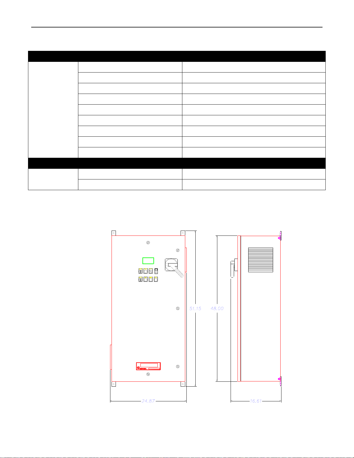
Specifications for Options
Option Code Temperature Controller Option
Thermocouple type (TCT): Type ‘K’
Sensor Input (TCP): 4-20mA scaled 0-2500 deg. F
Alarm relay rating: 5A @ 120VAC resistive, 3A @ 240VAC
Sample rate: 10 HZ
TCT & TCP
Option Code Voltmeter Option
VM
DIMENSIONS
Figure 6-1 Model 930
Dimensions
Overall
Calibration accuracy: +/- 0.2% of full scale +/- 1 digit
Control modes: PID or PI, PD, P only, or On/Off
Temperature stability:
Noise Rejection: Common Mode > 100 dB, Series Mode > 70 dB
Autotune: Operator initiated
RMS Voltage transducer: 0-600 VAC to 0-5 VDC
Overall accuracy: +/- 2 VAC
Figure 6-1 displays the overall dime nsi ons o f the Mo del 93 5 po wer control system.
The dimensions include the side vents and door handle.
5uV/°C max, 3uV/°C typical
Research, Inc. Page 22 of 25
Page 27
Model 930 ControlIRTM Instruction Manual Dimensions and Specifications
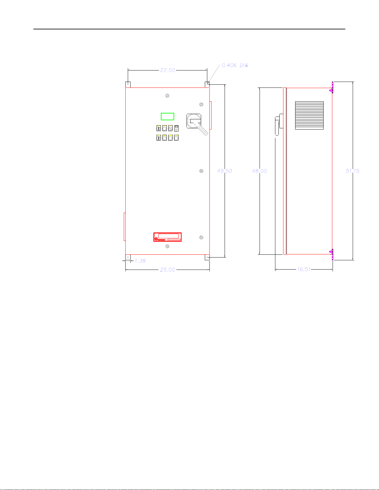
Figure 6-2 Wall Mounting
Dimensions
Figure 6-2 shows the mounting dimensions using the supplied brackets.
Research, Inc. Page 23 of 25
Page 28
Model 930 ControlIRTM Instruction Manual Dimensions and Specifications
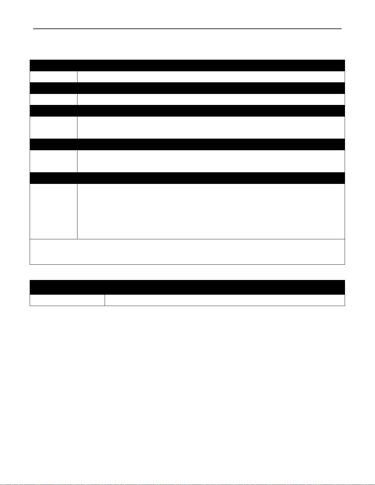
Ordering Information
Model Product Description
935 Three Phase SCR Power Control System
Code Enclosure
A Wall Mount
Code Line Voltage
240 240 Volts AC
480 480 Volts AC
Code Current Cap acity
120 120 Amps
160 160 Amps
Code Options
(2)
TCP
Temperature Controller – 4/20 mA, Pyrometer Input
(2)
TCT
Temperature Controller – Thermocouple Input
(2)
VM
Digital Voltmeter
(1)
LL Lamp-out Detection
00 None
Overall Dimensions (including side vents, door handle and mounting brackets): 51.15 inches
(1)
High (1299.2mm) x 16.34 inches Deep (415mm).
(2) System available with either option TCP, TCT or VM. Select one only.
Ordering Example
Model Enclosure
Line
Voltage
Typical Model Number 930 A 480 120 TCP LL
Current
Capacity
Options
Research, Inc. Page 24 of 25
Page 29

Model 930 ControlIRTM Instruction Manual Dimensions and Specifications
Spare and Replacement Parts
Description Part Number
Fuse – 200 Amp 600 VAC (For use with 160 Amp version)
Fuse – 150 Amp 600 VAC (For use with 120 Amp version)
Fuse – 1 Amp Time Delay "CC"
Fuse – 2 Amp 5x20 mm Fast Act.
True RMS AC Voltage Transmitter
Digital Meter – 0-600 VAC
Control Transformer – 70 VA
Potentiometer – 1K, 10 Turn
Digital Dial
Switch – 2 Position Selector (contact blocks separate, see below) Remote/Local
Switch – 3 position spring return to cent er (contact blocks sold separately)
Switch – contact block 1 CON NO
Switch – contact block 2 CON NO NC
Pilot Light Module 120 VAC
Model XT19 Temperature Controller (Thermocouple Input)
Model XT19 Temperature Controller (4-20mA, Pyrometer Input)
Main Disconnect Switch 3P 200A
Handle for Disconnect Switch
Contactor 3 Pole 200A
Model 3629B Power Controller 160A
Model 3629B Power Controller 120A
Programmable Logic Controller 8AC in 6 Relay out with 915/935-PRJ Software
Fuse Load 80A, 600VAC (Load Fuse 120A Version)
Fuse Load 100A, 600VAC (Load Fuse 160A Version)
Control Transformer 100VA 240/480-120V
089330-001
086160-015
086445-015
087146-002
097832-002
097831-005
099366-001
055769-004
042952-000
087543-002
087543-004
087545-001
087545-001
092452-001
097399-002
097399-003
105286-001
105287-001
105289-001
099458-043
099458-041
099559-001
086797-001
086160-010
075475-001
Research, Inc. Page 25 of 25
 Loading...