

Page 1
I
Model 6020 User’s Manual
Dry
Infrared Heaters
Publication #: A106920-001 Rev. 1
R
March 2003
Another quality product from:
7128 Shady Oak Road, Eden Prairie, MN 55344
Phone: (952)949-9009 Fax: (952)949-9559
E-mail: [email protected]
www.researchinc.com
Page 2

Copyright © 2003 by Research, Inc. All rights re ser ved . U nder copyright laws, neither the documentati on
nor the software may be copied, photocopied, reproduced, translated, or reduced to any electronic medium
or machine-readable form, in whole or in part, without the prior written consent of Research, Inc., except in
the manner described in the documentation.
Research, Inc. reserves the right, without notice, to alter or improve the designs or specifications of the
products described herein. No warranty or guarantee of any kind is expressed or implied by information
contained herein.
Printed in the U.S.A.
Page 3

Dear Valued Customer:
Thank you for purchasing a Model 6020 DryIR
®
infrared heater. We believe it is the finest
heating system of its type and are confident you will think so also.
This instruction manual has been carefully prepared to ensure you will be able to easily install
and operate the Model 6020 heater and to fully realize all its inherent capabilities. We invite your
comments as well as any issues you may have regarding this manual or the Model 6020.
Requirement
Appropriate Contact
Additional information regarding application Your local sales representative.
of the Model 6020 heater or other Research Inc.
products.
Ordering additional Research Inc. products or Manuals. Your local sales representative
or Research, Inc. Customer
Service (952) 949-9009
Technical assistance and training. Research Inc. Factory Service
(952) 949-9009
Once again, let us welcome you to the growing family of Research Inc. customers. We look
forward to working with you in the future.
Sincerely,
Terry Nigon
President
Research Inc.
Page 4

Table of Contents
Section 1 – Introduction.......................................................................................... 1-1
Section 2 – Features & Benefits.............................................................................. 2-1
Section 3 – Specifications........................................................................................ 3-1
Dimensions............................................................................................................. 3-1
Ordering Information.............................................................................................. 3-2
Accessories, Spare & Replacement Parts............................................................... 3-2
Section 4 – Safety..................................................................................................... 4-1
Section 5 – Installation…………………………………………….……………... 5-1
5.1 Un-pack and Check for Damage.......... ..................... ..................... ................... 5-1
5.2 Mounting the Heater......................................................................................... 5-1
5.3 Electrical Connections...................................................................................... 5-1
Section 6 – Maintenance......................................................................................... 6-1
6.1 Lamp Removal/Replacement/Installation......................................................... 6-1
6.2 Cleaning the Reflector...................................................................................... 6-2
Section 7 – Spare & Replacement Parts................................................................ 7-1
APPENDIX.........................................................………………………………...... A-1
106920-001 Rev. 1
Page 5
Section 1 – INTRODUCTION
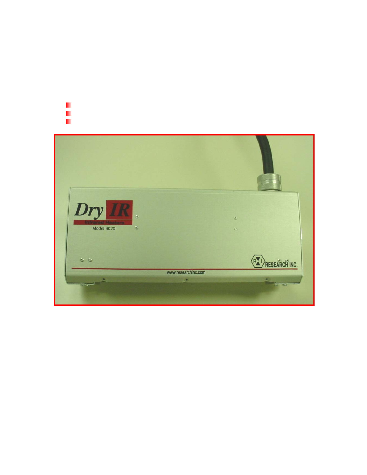
The Model 6020 DryIR® Infrared line heater is designed for drying applications that
requires a clean, responsive, non-contact heat source.
Typical applications for the Model 6020 include:
Water-based drying
Solvent-based drying
Adhesive curing
The Model 6020 includes the following major components:
Heater Module – The heater consists of a polished aluminum reflector that directs the
infrared energy generated by two 1000-watt medium-wave quartz halogen lamps, that are
included with the heater. Heated widths of one-half, one, and two inches (13, 25, and 54
mm) are offered for the Model 6020, with a heated length of 10 inches. Additional lamps
can be ordered separately from the heater.
Air Cooling – An integrated fan blows air past the lighted lamps resulting in a heated air
impingement on the target product surface. When combined with quartz lamps, the result
is immediate evaporation and fast drying rates.
106920-001 Rev. 1 1-1
Page 6
Electrical Cable – The Model 6020 heater is electrically wired from the lamps to an
intermediate terminal block within the heater. An 8-foot (2.4 m) electrical cable is
supplied with each heater.
Optional Mounting Kit – The Model 6020 can be ordered with an optional mounting
kit.
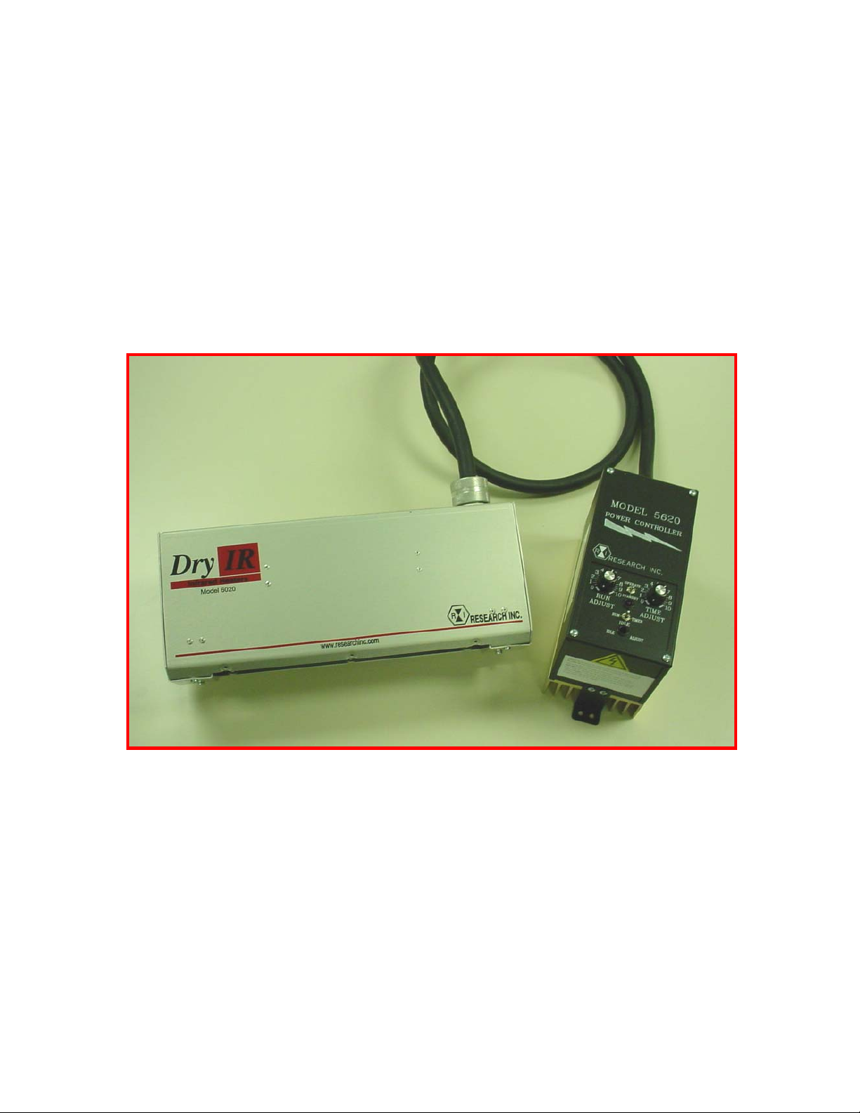
Optional Power Control System – The Model 6020 can be ordered with a Power
Control "PC" Option. This configuration consists of the Model 6020 heater, a Model
5620 ControlIR® SCR Power Controller, and eight feet (2.4m) of electrical cable
connecting the heater to the controller. Please see the Model 5620 ControlIR® product
data sheet for further detail.
Figure 1-1. Model 6020 with the PC Option
106920-001 Rev. 1 1-2
Page 7
Section 2 – FEATURES & BENEFITS
The design and functionality of the Model 6020 supplies a variety of features and related
benefits:
Rapid Response – The medium-wave quartz halogen lamps heat up and cool down
instantly in response to power control signals.
Continuous Operation – The aluminum construction of the Model 6020 combined with
the air-cooling, allows the heater to withstand continuous high-temperature operation.
Modular Design – The modular design of the heater allows units to be installed in a
variety of configurations suitable for many applications.
Electrically Enclosed Heater Module – All electrical connections for the Model 6020
are completely enclosed for safety.
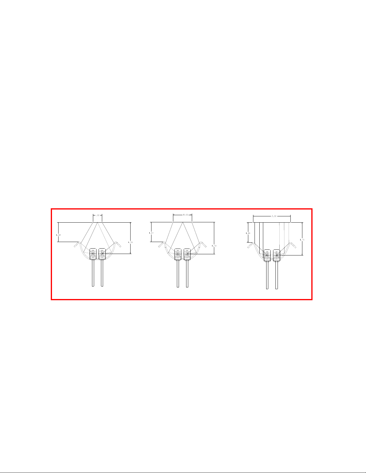
Target Product Sizes – The Model 6020 generates radiant energy and directs it into a
band approximately 10 inches (254 mm) long and 0.5, 1.0 or 2.0 inches (13, 25, or 51
mm) wide. See the schematic below for reflector options.
0.5-Inch Reflector (400 W/in2)
1.0-Inch Reflector (200 W/in2)
Figure 2-1. Model 6020 Reflector Options
2.0-Inch Reflector (100 W/in2)
Heat Flux Density – Heat flux densities up to approximately 400 watts per square-inch
(62 watts per square-cm) can be achieved with the Model 6020 with the 0.5 inch width,
operating at the lamp’s rated voltage. Heat flux density is a product of the lamp type,
applied voltage, and distance between the lamp and the target surface. For best results, it
is recommended that the Model 6020 be operated at a distance of 1.0 inch from the
product.
Controllable Energy Output – The infrared energy emitted from the heater can be
adjusted to match the heating requirements of a variety of applications.
The Model 6020 ordered with the ‘PC’ option is a complete heating solution designed
with a number of features including heater on/off control switching, potentiometer local
control, and a timer.
106920-001 Rev. 1 2-1
Page 8
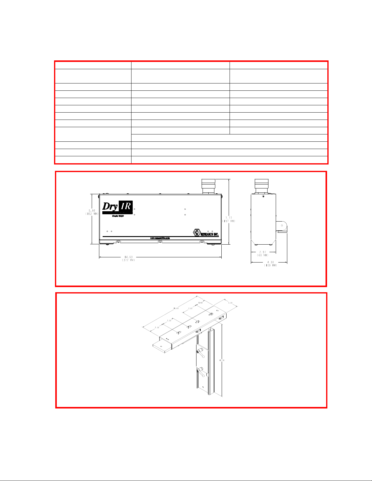
Section 3 - SPECIFICATIONS
Maximum Drying Width
Overall Length 14.63 inches (372 mm) 14.63 inches (372 mm)
Heated Length 10 inches (254mm) 10 inches (254mm)
Lamps (2 Total) 1000W, 120V Rapido Lamps 1000W, 240V Rapido Lamps
Lamp Orientation Horizontal Only Horizontal Only
Amps at Applied Voltage 17 amps 8.5 amps
Power at Applied Voltage 2.0 kW 2.0 kW
Site Requirements
Blower Air Volume 75 CFM (2.1m³/min)
Power Connection Electrical power cord (8-foot (2.5 m) length)
Mounting 6 mm threaded mounting screw (Mounting Kit available)
0.5, 1.0, or 2.0 inches
(13, 25, or 51 mm)
120V/25 amp service 240V/15 amp service
Personnel to position the system in place
120 Volts 240 Volts
0.5, 1.0, or 2.0 inches
(13, 25, or 51 mm)
Figure 3-1. Model 6020 DryIR Dimensions - Inches (mm)
Figure 3-2. Optional Mounting Kit - Inches
106920-001 Rev. 1 3-1
Page 9
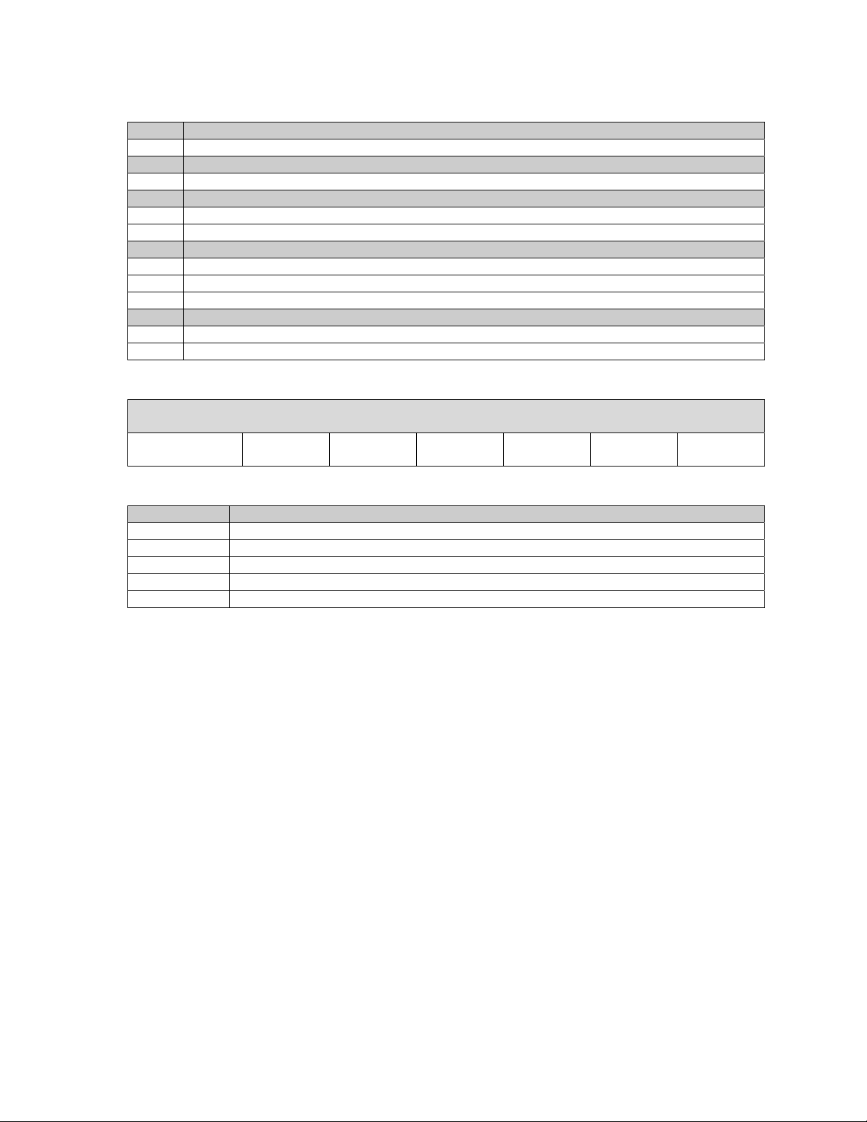
Ordering Information – Model 6020
Model Product Description
6020 DryIR Infrared Heater (Includes 2 medium-wave lamps)
Code Dryer Length
10 10 inches (254 mm)
Code System Voltage
120 120 Volts
240 240 Volts
Code Drying Width
A 0.5 inches (13 mm)
B 1 inch (25 mm)
C 2 inch (50 mm)
Code Additional Options
MK Mounting Kit
PC Model 6020 supplied with Model 5620 SCR Power Controller and interface wiring
Ordering Example – Model 6020
Typical Model
Number
Model
6020 10 240 A MK PC
Dryer
Length
System
Voltage
Drying
Width
Additional
Options
Accessories, Spare & Replacement Parts – Model 6020
Model Description
106876-001 Mounting Kit
083502-004 Replacement Electrical Power Cord (8-foot (2.5 m) length)
106877-003 Lamp Kit, 120V (includes 2 lamps and connectors)
106877-002 Lamp Kit, 240V (includes 2 lamps and connectors)
M6020 Additional Model 6020 Operation Manual (one supplied with each heating module)
Additional
Options
106920-001 Rev. 1 3-2
Page 10

Section 4 – SAFETY
GENERAL: The Model 6020 heater is designed for safe operation. Nevertheless,
installation, maintenance, and operation of the heater can be dangerous for a careless
operator or maintenance person. For your safety and the safety of others, read the
instructions in this Instruction Manual and follow these safety practices to help prevent
accident or injury.
INFRARED RADIATION - CAUTION! Continuous exposure to high intensity
infrared radiation at close proximity could be harmful to eyes or skin. Although infrared
lamps emit negligible ultra violet electromagnetic radiation, harmful burns can still result
if an operator is in close contact with lamps being operated at high intensity.
Because of the brilliant light emitted by infrared lamps at full intensity, it is
recommended that eyes be shielded from the glare if observing the lamps for an extended
period of time. Use suitable shaded lenses or dark glasses.
HIGH TEMPERATURES: Parts of the heater may exceed 500°F (260°C). Contact
with the lamps, reflector, or metal parts near the lamps may cause severe burns.
WARNING!
NEVER place hands under or in front of the heating elements.
ALWAYS allow heating element to cool at least three minutes before touching the lamps
or adjacent parts.
ELECTRICAL SAFETY: There is danger of electrical shock when servicing the heater.
CAUTION! Observe all applicable local and national electrical codes and ensure that a
safe electrical ground system is installed before attempting to operate the heater. Refer to
the Section 5 for proper installation procedures.
WARNING!
ALWAYS disconnect the external power lines prior to servicing the heater.
ALWAYS disconnect the power lines AND any optional interlock circuits before
installing or changing lamps.
NEVER operate the heater with end covers removed.
106920-001 Rev. 1 4-1
Page 11

FIRE SAFETY:
1. Obey the same fire-safety rules you observe when working with hot plates,
propane or acetylene torches, soldering irons, and other equipment that operates at
extremely high heat.
2. Remove all solids, liquids, and gases that burn easily from the area around the
heater.
3. Know where the nearest fire extinguisher is located and how to use it.
4. Know how to put out fire from all the types of material near the heater.
106920-001 Rev. 1 4-2
Page 12
Section 5 – INSTALLATION
5.1 UNPACK AND CHECK FOR DAMAGE: Remove the Model 6020 heater
from its shipping container and associated packaging. Check the unit for any potential
damage due to shipping. In the unlikely event damage has occurred, keep all shipping
containers and materials in order to file a damage claim with the shipping company
responsible for shipping the unit.
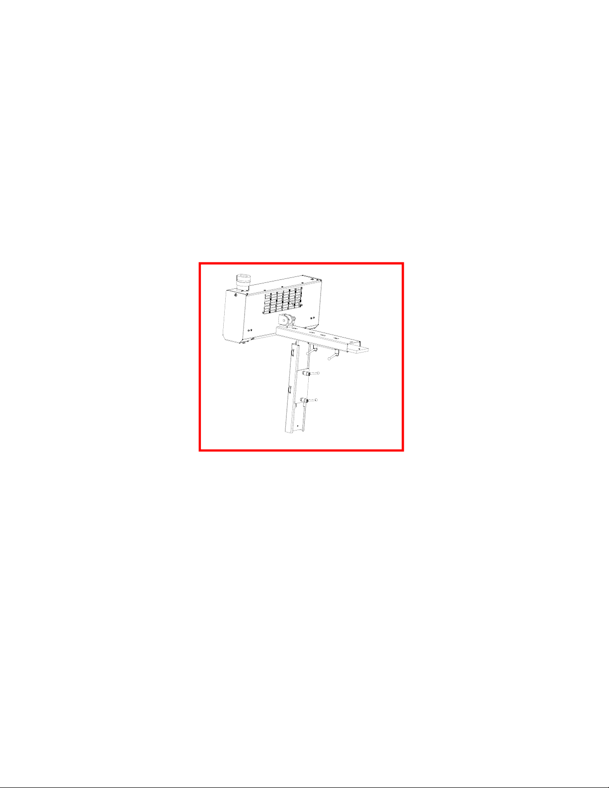
5.2 MOUNTING THE HEATER: The Model 6020 heater should be mounted to a
framework or structure that is designed to support the weight of the heater and provide
stability to the unit. If a transport is being used in the application, the heater module
should be mounted so it is level with the transport and should be spaced from one inch
(25.4 mm) above the transport surface.
Figure 5-1. Model 6020 Pictured with Optional Mounting Kit
5.3 ELECTRICAL CONNECTIONS: The lamps of the Model 6020 are electrically
wired to an intermediate terminal block within the heater. An electrical schematic can be
found in the Appendix.
Each heater is supplied with an 8-foot (2.4 m) electrical cable. If ordered with the PC
option, this cable is directly hard wired into the Model 5620 power controller.
106920-001 Rev. 1 5-1
Page 13
Section 6 – MAINTENANCE
The repair and maintenance of the Model 6020 includes replacement of the lamps and
cleaning of the reflector.
6.1 LAMP REMOVAL/REPLACEMENT/INSTALLATION: The lamps are
included with the Model 6020 heater, but are shipped separately to avoid breakage. The
following procedure details the process to install or replace the lamps in the Model 6020
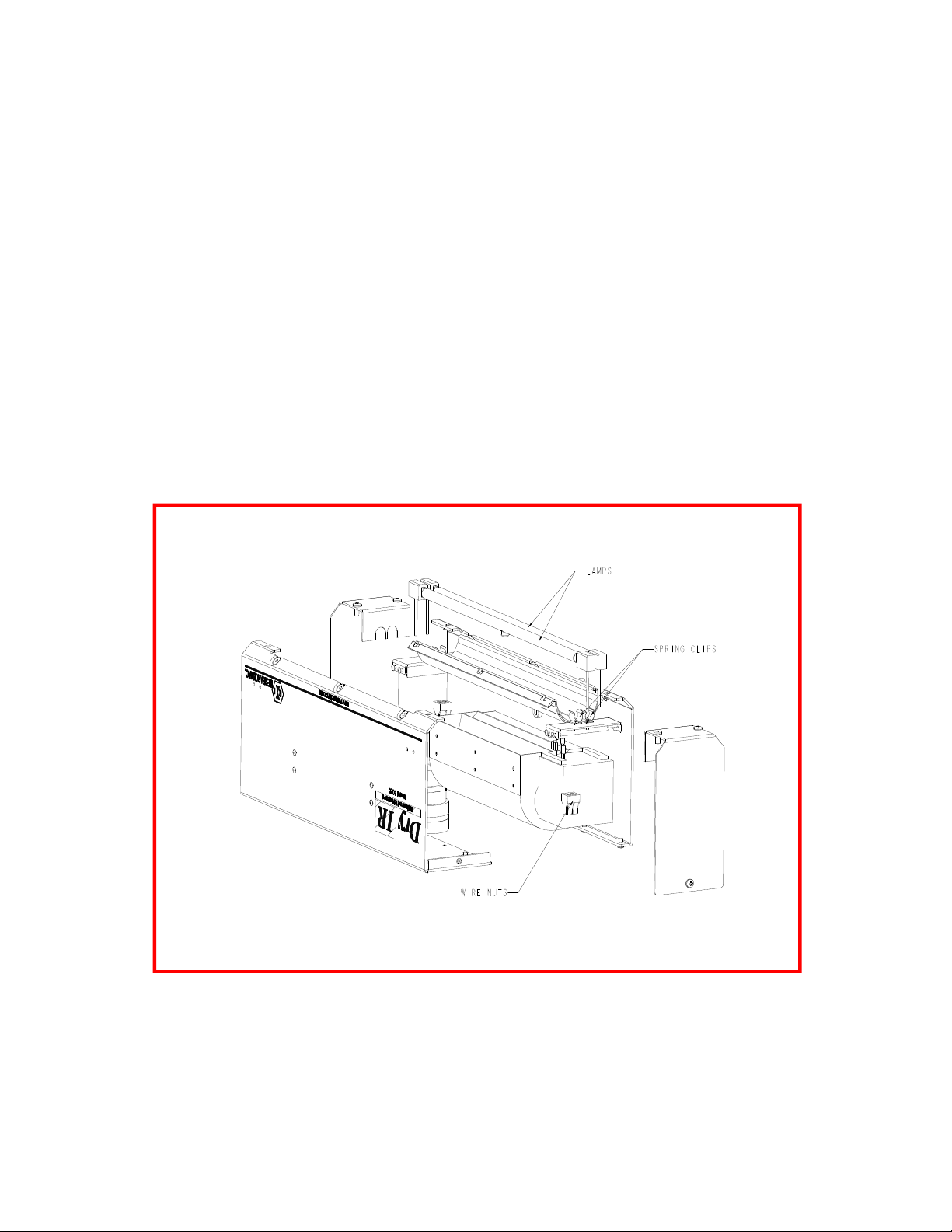
(reference Figure 6-1):
Note:
• Remove all power from the heater BEFORE attempting to install/replace the
lamps.
• Allow a minimum of ½-inch (12 mm) of slack in the lamp lead so that the lead
is not taut when inserted into the lamp terminal block.
• Always take care to handle all lamps by the ceramic end seals and use clean
cotton or latex gloves to prevent contamination of the quartz lamp envelope.
Figure 6-1. Model 6020 Spring Clip and Wire Nut Locations
1. Remove end-cover screws.
2. Remove end covers on both ends of the heater.
3. Pull the lead wires out of the wire nuts. (see Figure 6-1).
106920-001 Rev. 1 6-1
Page 14

4. Gently pull the lamp out of the lamp clips, and set aside for disposal.
5. While holding the replacement lamp by the end seals, place the lamp into the
lamp clips located on each end of the heater. Orient the lamp so that the gas fill
tip, formed into the quartz tube of the lamp, points out away from the reflector.
6. Insert the bare wire of each insulated lamp lead into the wire nut that previously
held the old lamp.
7. Form a loop within each lead along its length. This loop will act as a strain relief
within the lead during normal operation of the heater.
8. Reinstall both end covers and secure each to the heater with the end cover screws.
6.2 Cleaning the Reflector: A clean reflector provides the greatest radiant efficiency.
If the reflector surface becomes contaminated, it reflects less energy. The energy that is
not reflected is absorbed by the reflector, and removed by the cooling water. This energy
is lost energy.
The following procedure should be used to clean the Model 6020 reflector:
1. Remove the lamp as described in Section 6.1 – Lamp
Removal/Replacement/Installation.
2. Clean the reflector with a mixture of warm water and common household
ammonia followed by a thorough wipe-down using a clean, water-dampened
flannel cloth.
3. Depending on the type of contamination present on the reflector, a suitable
solvent may be required to remove the contamination. The solvent must be
selected based on its inability to adversely affect the aluminum reflector.
4. Thoroughly wipe the reflector using the warm water/household ammonia mixture
followed by the dampened flannel cloth.
5. Replace the lamps and the heater end covers as outlined in Section 6.1 – Lamp
Removal/Replacement/Installation.
106920-001 Rev. 1 6-2
Page 15
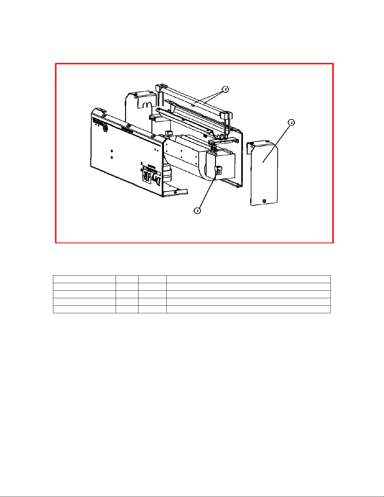
Section 7 – SPARE & REPLACEMENT PARTS
Figure 7-1. Model 6020 Parts Identification
COMPONENT NO. QTY ITEM DESCRIPTION
055923-001 2 1 PUSHWIRE CONN 2-18 AWG 4 POS.
106877-003 2 2A LAMP KIT - RAPIDO 1000 W. CER. END, 120V
106877-002 2 2B LAMP KIT - RAPIDO 1000 W. CER. END, 240V
106763-001 2 3 FAB - END REFLECTOR, 0.75 PRT
Table 7-1. Model 6020 Spare & Replacement Parts
106920-001 Rev. 1 7-1
Page 16

APPENDIX
106920-001 Rev. 1 A-1
 Loading...