

Page 1
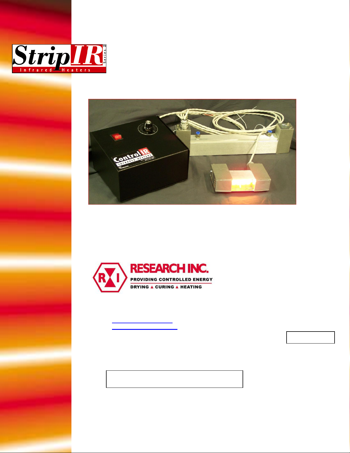
Model 5306B User’s Manual
Rev.112811
Instruction Manual
StripIR Model 5306B
7128 Shady Oak Road Eden Prairie, MN 55344
(952) 949-9009 Fax (952) 949-9559
Another quality product from:
Page 2

Page 3

Table of Contents
Section 1 – Introduction.......................................................................................... 1-1
Section 2 – Features & Benefits.............................................................................. 2-1
Section 3 – Specifications........................................................................................ 3-1
Dimensions............................................................................................................. 3-2
Ordering Information.............................................................................................. 3-3
Accessories, Spare & Replacement Parts............................................................... 3-3
Section 4 – Safety..................................................................................................... 4-1
Section 5 – Installation…………………………………………….……………... 5-1
5.1 Un-pack and Check for Damage....................................................................... 5-1
5.2 Mounting the Heater......................................................................................... 5-1
5.3 Heater Cooling Connections............................................................................. 5-2
5.4 Electrical Connections...................................................................................... 5-2
Section 6 – Maintenance......................................................................................... 6-1
6.1 Lamp Removal/Replacement/Installation......................................................... 6-1
6.2 Quartz Window Cleaning and Replacement..................................................... 6-2
6.3 Cleaning the Reflector...................................................................................... 6-3
Section 7 – Spare & Replacement Parts................................................................ 7-1
106837-001 Rev. 1
Page 4
Section 1 – INTRODUCTION
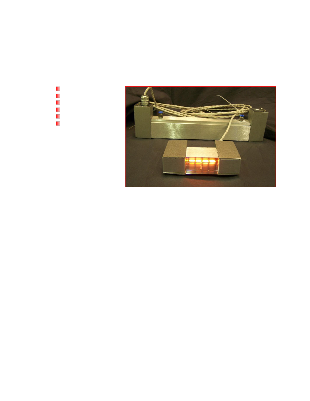
The Model 5306B StripIR® Infrared line heater is designed for use in any application that
requires a clean, responsive, non-contact heat source.
Typical applications for the Model 5306B include:
Drying paint
Curing adhesive
Drying ink
Forming plastic
Stress relieving metal
Heat treating
The Model 5306B includes the following major components:
Heater Module – The heater consists of a specular aluminum reflector that directs the
infrared energy generated by one ceramic end-seal ‘T-3 style’ quartz halogen lamp
factory-installed in the heater. Heated lengths of 2.56, 5, 11, 16, 25, and 38 inches (65,
127, 279, 406, 635, and 965 mm) are offered for the Model 5306B. Additional lamps can
be ordered separately from the heater.
Water Cooling – Adequate cooling water is required during operation of the Model
5306B. Flexible tubing and plumbing fittings are supplied with each heater for easy
installation. Required cooling water flow rates are listed in Specifications.
Electrical Cable – The Model 5306B heater is electrically wired from the T3 lamp to
intermediate terminal block within the heater. An 8-foot (2.4 m) electrical cable is
supplied with each heater.
Optional Quartz Window – A quartz window can be ordered along with each size of the
Model 5306B. When installed in the heater, the quartz window protects the aluminum
reflector and lamp from contaminants released in the heating process, resulting in
maximum efficiency of the heater.
1. 106837-001 Rev. 1 1-1
Page 5
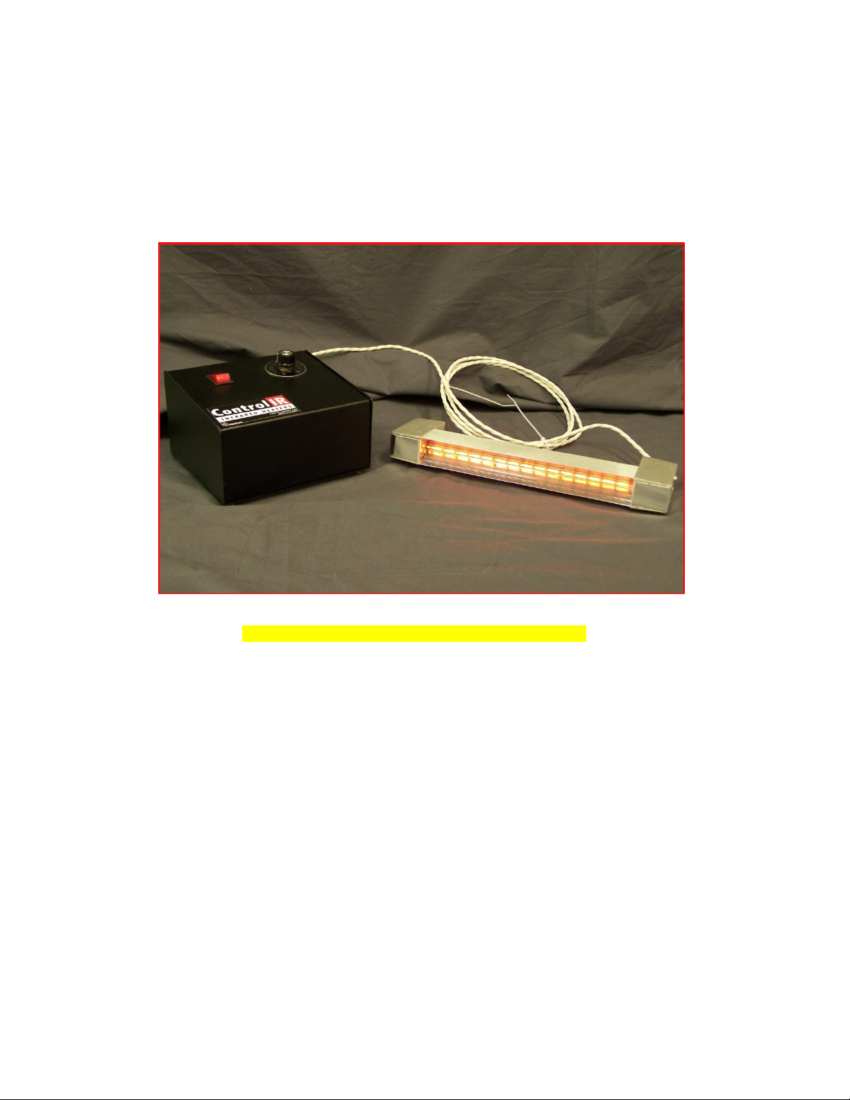
Figure 1-1. Model 5306 with the Control Option
Optional Power Control System – The Model 5306B can be ordered with the ‘PC’
option. This configuration consists of the heater, the Model 5420 ControlIR® controller,
and eight feet (2.4 m) of electrical cable connecting the heater to the controller. Please
see the Model 5420 ControlIR® product data sheet for further detail.
1. 106837-001 Rev. 1 1-2
Page 6

Section 2 – FEATURES & BENEFITS
The design and functionality of the Model 5306B supplies a variety of features and
related benefits:
Rapid Response – The quartz halogen lamps heat up and cool down instantly in response
to power control signals. They reach 90 percent of full operating temperature within three
seconds of a cold start. The radiant energy dissipates to ten percent five seconds after the
power supply is disconnected.
Continuous Operation – The cast end enclosure and extruded aluminum construction of
the Model 5306B, combined with the liquid, allows the heater to withstand continuous
high temperature operation.
Controllable Energy Output – The infrared energy emitted from the heater can be
adjusted to match the heating requirements of a variety of applications.
The Model 5306B ordered with the Controller option is a complete heating solution
designed with a number of features including heater on/off control switching,
potentiometer local control, with or without a timer or a remote 4-20 ma control signal.
106837-001 Rev. 1 2-1
Page 7
Specification
5306B-02
5306B-05
5306B-10
5306B-16
5306B-25
5306B-38
Weight, Pounds (kg)
1.6 (0.60)
2.2 (0.82)
3.1 (1.2)
4.1 (1.5)
5.8 (2.2)
8.1 (3.0)
Lamp Type
QIH120-
1000RI2
QIH2401000R12
QIH2402000R12
QIH2403000R12
QIH6005000R12
QIH4803800R12
Lamp Part Number
106587-001
103390-002
103390-004
103390-012
103390-008
103390-010
Lighted Length, Inches
(mm)
2.56 (65)
5.0 (127)
11.0 (279)
16.0 (406)
25.0 (635)
38.0 (965)
Watt Density (W/in)
266
133
125
125
93
66
Rated Voltage
120
240
240
240
600
480
Total Power Dissipated @
Rated Voltage, Watts
1000
1000
2000
3000
5000
3800
Total Current @ Rated
Voltage, Amps
8.3
4.2
8.2
12.5
8.3
7.9
Cooling Water Flow1, GPM
(lpm)
0.15 (0.5)
0.15 (0.5)
0.25 (0.9)
0.4 (1.5)
0.6 (2.2)
0.45 (1.7)
Section 3 - SPECIFICATIONS
1. Cooling water must be used on all Model 5306B heaters while in operation.
106837-001 Rev. 1 3-1
Page 8
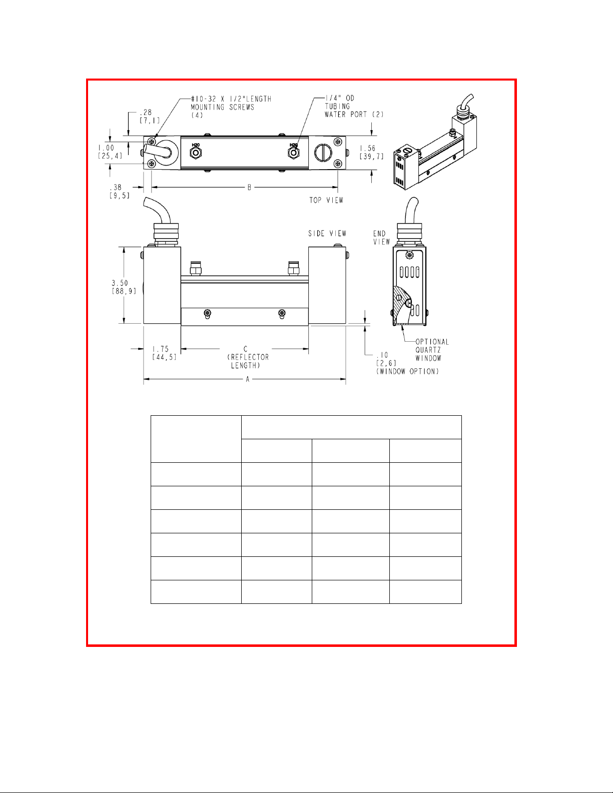
Model Number
Dimension
A
Inches (mm)
B
Inches (mm)
C
Inches (mm)
5306B-02-1000
6 (152.4)
2.5 (63.5)
5.3 (133.4)
5306B-05-1000
9.5 (241.3)
6 (152.4)
8.8 (222.3)
5306B-10-2000
14.5 (368.3)
11 (279.4)
13.8 (349.3)
5306B-16-3000
20.1 (510.5)
16.6 (421.5)
19.4 (491.5)
5306B-25-3550
29.5 (749.3)
26 (660.4)
28.8 (730.3)
5306B-38-3800
42.5 (1079.5)
39 (990.6)
41.8 (1060.5)
Figure 3-1. Model 5306 Dimensions
106837-001 Rev. 1 3-2
Page 9
Model
Product Description
5306B
Infrared Strip Heater (Installed lamp included)
Code
Length
Lighted Lamp Length
Reflector Length
Overall Heater Length
02-1000
2 in (51 mm)
2.56 in (65 mm)
5.3 in (133 mm)
6 in (152 mm)
05-1000
5 in (127 mm)
5 in (127 mm)
8.8 in (222 mm)
9.5 in (241 mm)
10-2000
10 in (254 mm)
11 in (279 mm)
13.8 in (349 mm)
14.5 in (368 mm)
16-3000
16 in (406 mm)
16 in (406 mm)
19.4 in (492 mm)
20.1 in (511 mm)
25-3550
25 in (635 mm)
25 in (635 mm)
28.8 in (730 mm)
29.5 in (749 mm)
38-3800
38 in (965 mm)
38 in (965 mm)
41.8 in (1061 mm)
42.5 in (1080 mm)
Code
Optional Equipment
00
No optional controls.
02
Controller including potentiometer
03
Controller including potentiometer and timer
04
Controller including an input for a remote 4-20 mA control signal
Model
Heating Chamber Length
Optional Equipment
Typical Model Number:
5306B
16-3000
03
Model
Description
Quartz Window Kit for:
W-5306B-02
2 Inch (51 mm) length
W-5306B-05
5 Inch (127 mm) length
W-5306B-10
10 Inch (254 mm) length
W-5306B-16
16 Inch (406 mm) length
W-5306B-25
25 Inch (635 mm) length
W-5306B-38
38 Inch (965 mm) length
Quartz Halogen, Ceramic End-Seal, Infrared Lamp for:
106587-001
Model 5194-02 (1000-watts, 120-volts)
103390-002
Model 5194-05 (1000-watts, 240-volts)
103390-004
Model 5194-10 (2000-watts, 240-volts)
103390-012
Model 5194-16 (3000-watts, 240-volts)
103390-008
Model 5194-25 (5000-watts, 600-volts/3550watts @480 volts)
103390-010
Model 5194-38 (3800-watts, 480-volts)
Other Available Lamps:
103390-001
Model 5194-05 (500-watts, 120-volts)
103390-003
Model 5194-10 (1000-watts, 240-volts)
103390-005
Model 5194-16 (1600-watts, 240-volts)
103390-007
Model 5194-25 (2500-watts, 480-volts)
103390-009
Model 5194-38 (3800-watts, 570-volts)
Accessories:
106684-001
Electrical Power Cable, 8-foot (2.4 m) length
106685-001
Water-Cooling Supply Kit
M5306B
Additional Operation Manual
Ordering Information – Model 5306B
Ordering Example – Model 5306B
Accessories, Spare & Replacement Parts – Model 5306B
106837-001 Rev. 1 3-3
Page 10
Section 4 – SAFETY
GENERAL: The Model 5306B heater is designed for safe operation. Nevertheless,
installation, maintenance, and operation of the heater can be dangerous for a careless
operator or maintenance person. For your safety and the safety of others, read the
instructions in this Instruction Manual and follow these safety practices to help prevent
accident or injury.
INFRARED RADIATION - CAUTION! Continuous exposure to high intensity
infrared radiation at close proximity could be harmful to eyes or skin. Although infrared
lamps emit negligible ultra violet electromagnetic radiation, harmful burns can still result
if an operator is in close contact with lamps being operated at high intensity.
Because of the brilliant light emitted by infrared lamps at full intensity, it is
recommended that eyes be shielded from the glare if observing the lamps for an extended
period of time. Use suitable shaded lenses or dark glasses.
HIGH TEMPERATURES: Parts of the heater may exceed 500°F (260°C). Contact
with the lamps, reflector, or metal parts near the lamps may cause severe burns.
WARNING!
NEVER place hands under or in front of the heating elements.
ALWAYS allow heating element to cool at least three minutes before touching the lamps
or adjacent parts.
ELECTRICAL SAFETY: There is danger of electrical shock when servicing the heater.
CAUTION! Observe all applicable local and national electrical codes and ensure that a
safe electrical ground system is installed before attempting to operate the heater. Refer to
the Section 5 for proper installation procedures.
WARNING!
ALWAYS disconnect the external power lines prior to servicing the heater.
ALWAYS disconnect the power lines AND any optional interlock circuits before
installing or changing lamps.
NEVER operate the heater with end covers removed.
106837-001 Rev. 1 4-1
Page 11

FIRE SAFETY:
1. Obey the same fire-safety rules you observe when working with hot plates,
propane or acetylene torches, soldering irons, and other equipment that operates at
extremely high heat.
2. Remove all solids, liquids, and gases that burn easily from the area around the
heater.
3. Know where the nearest fire extinguisher is located and how to use it.
4. Know how to put out fire from all the types of material near the heater.
106837-001 Rev. 1 4-2
Page 12
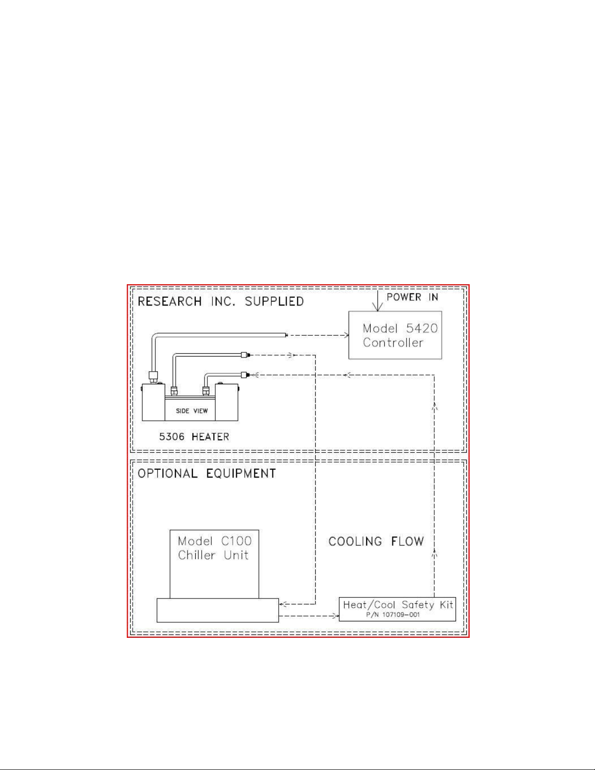
Figure 5-1. Typical Model 5306B Installation.
Section 5 – INSTALLATION
5.1 UNPACK AND CHECK FOR DAMAGE: Remove the Model 5306B heater
from its shipping container and associated packaging. Check the unit for any potential
damage due to shipping. In the unlikely event damage has occurred, keep all shipping
containers and materials in order to file a damage claim with the shipping company
responsible for shipping the unit.
5.2 MOUNTING THE HEATER: The Model 5306B heater should be mounted to a
framework or structure that is designed to support the weight of the heater and provide
stability to the unit. Four #10-32 threaded holes are located on the top surface of the
heater and are designed for mounting the heater (see Figure 3-2).
Note: All Research Inc. lamps associated with the Model 5306B heater are designed for
vertical operation, except for the lamps used in the 5306B-02.
106837-001 Rev. 1 5-1
Page 13

5.3 HEATER COOLING CONNECTIONS: Each Model 5306B is designed with
two ‘quick-disconnect’ fittings protruding from the top of the heater cover. The fittings
located at the outer ends of the heater are the inlet/outlet cooling water ports.
Both fittings accept 1/4-inch outer-diameter flexible nylon tubing. A 20-ft. (6 m) length
of tubing and two additional quick-disconnect fittings are shipped with each Model
5306B heater. The tubing should be cut to specific lengths so that cooling water can be
supplied to the heater. The additional fittings should be used for connecting the tubing
directly to the cooling water source.
Once cut to the appropriate lengths, each individual tube length should be inserted into
the appropriate fittings on both the heater and the cooling water sources. Figure 5-2
details a typical installation for the Model 5306B heater.
Proper coolant flow must be maintained during operation of the heater. See Section 3 –
Specifications for required cooling-water flow for each Model 5306B heater size.
5.4 ELECTRICAL CONNECTIONS: The T3 lamp of the Model 5306B is
electrically wired to an intermediate terminal block within the heater.
Each heater is supplied with an 8-foot (2.4 m) electrical cable. If ordered with the PC
option, this cable is directly hard wired into the Model 5620 power controller.
106837-001 Rev. 1 5-2
Page 14
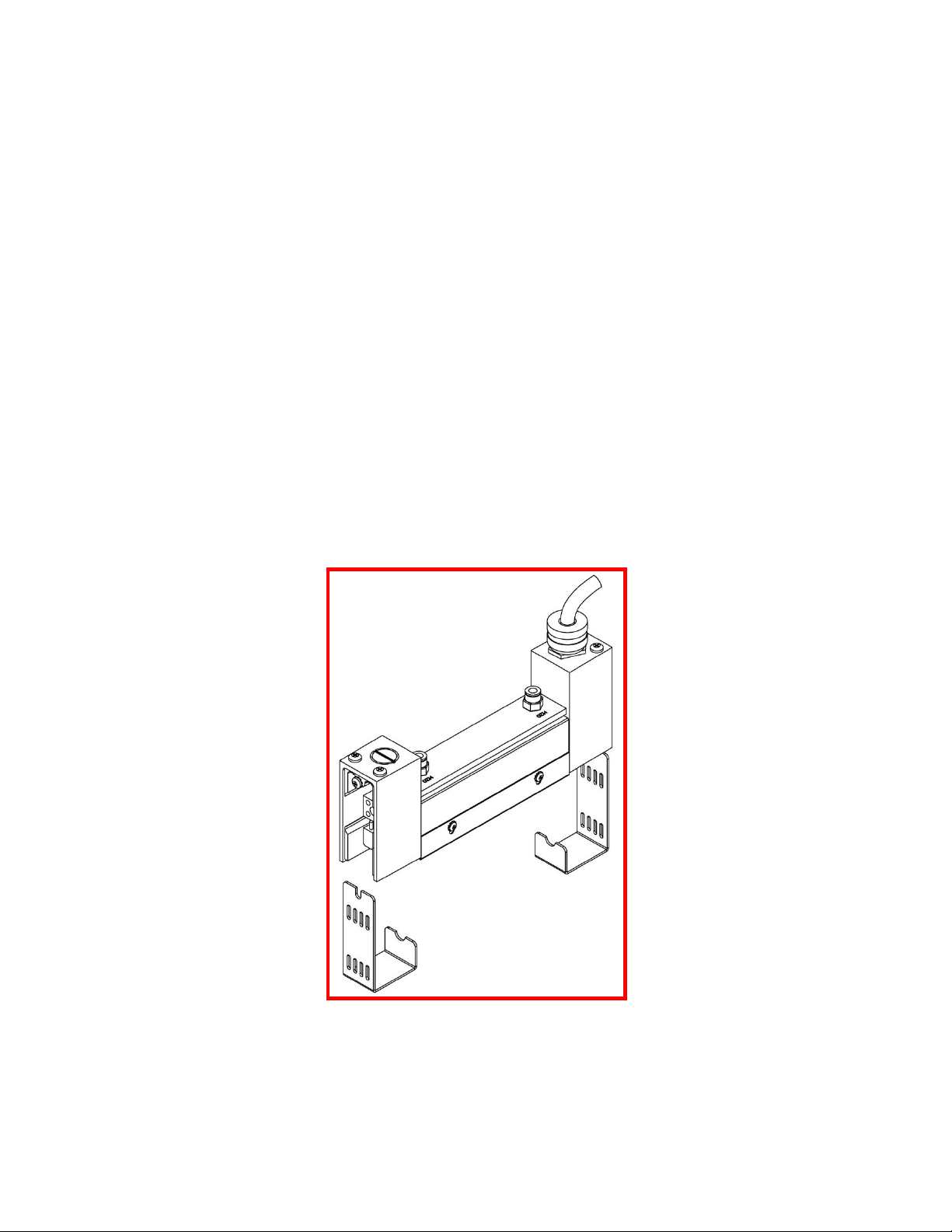
Figure 6-1. Model 5306B End Cover Removal.
Section 6 – MAINTENANCE
The repair and maintenance of the Model 5306B includes replacement of the T3-style
lamp and quartz window and cleaning of the reflector.
6.1 LAMP REMOVAL/REPLACEMENT/INSTALLATION: The T3-style lamp
is installed into the Model 5306B heater when shipped from the factory. The following
procedure details the process to replace the lamps in the Model 5306B (reference Figure
6-1,& 6-2):
Note:
Remove all power from the heater BEFORE attempting to install/replace the
lamp.
Allow a minimum of ½-inch (12 mm) of slack in the lamp lead so that the lead
is not taut when inserted into the lamp terminal block.
Always take care to handle all lamps by the ceramic end seals and use clean
cotton or latex gloves to prevent contamination of the quartz lamp envelope.
1. Remove end-cover screws (1 per end cover).
2. Remove end covers on both ends of the heater.
106837-001 Rev. 1 6-1
Page 15
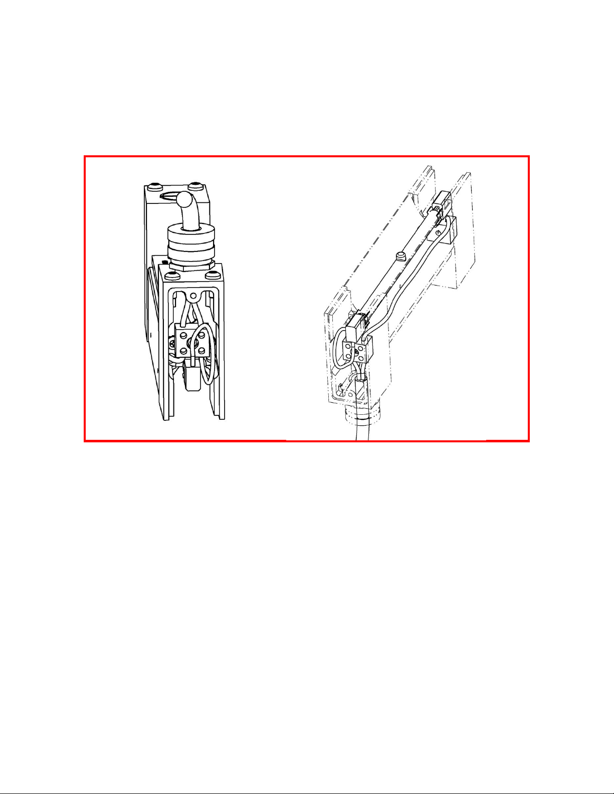
Figure 6-2. Model 5306 Lamp Removal.
3. Loosen (do not remove) the setscrews in the ceramic terminal block on each end
of the heater and remove the lamp lead from the terminal block. (see Figure 6-2).
4. While holding the lamp, gently pull the lead wires out of the ceramic terminal
blocks, out of the lamp clips, and set the old lamp aside for disposal. (The model
5306B-02 does not have lamp clips, but a half-circle groove that the lamp fits in.)
5. If the heater has a window installed it may have to be removed before the lamp
can be removed. Remove the end cover enclosures screws with a 9/64 hex
wrench. This will allow the window to be removed and access to the lamp. Install
the new lamp and install the window back into the reflector. With the 2 hex
screws remount the end enclosure back onto the reflector.
6. While holding the replacement lamp by the ceramic end seals, place the lamp into
the lamp clips located on each end of the heater. Orient the lamp so that the gas
fill tip, formed into the quartz tube of the lamp, points out away from the
reflector.
7. Insert the bare wire of each insulated lamp lead into the ceramic terminal block
position that previously held the old lamp. Push each lead wire into the terminal
block far enough so, that when tightened, the setscrew will hold the lead securely.
8. Tighten the setscrews in each terminal block so the lead wires are held securely.
Note: tighten the terminal block set screws to a torque of 0.6 Ft.-Lbs. [0.82 N-m].
106837-001 Rev. 1 6-1
Page 16

9. Form a loop within each lead along its length from the top of the cooling manifold
and the ceramic terminal block. This loop will act as a strain relief within the lead
during normal operation of the heater.
10. Reinstall the quartz window by replacing the screws in the window brackets.
11. Reinstall both end covers and secure each to the heater with the two screws per
end cover.
Note: tighten the end cover screws to a torque of 1.7 Ft.-Lbs. [2.3 N-m].
6.2 Quartz Window Cleaning and Replacement: The optional quartz window can
be replaced or removed from the Model 5306B for periodic cleaning. Use the following
procedure to remove/reinstall/clean the quartz window:
1. Loosen the screw that holds the lamp end cover to the end enclosure and remove
the end cover from the end without the electrical wires coming out of the end
enclosure. Remove the lamp lead from the ceramic block. Unclip the lamp from
its holder. With a 9/64 hex wrench remove the 2 screws that mounts the
enclosure to the reflector.
2. Carefully slid the window out of the reflector.
3. If cleaning the window, use Isopropyl Alcohol and a clean, dry, lint-free cloth.
After cleaning, do not touch the inside surface of the window unless wearing
cotton gloves.
4. Reinstall the quartz window into the reflector and reassemble the end enclosure,
hook the lamp back up and clip it back into place..
6.3 Cleaning the Reflector: A clean reflector provides the greatest radiant efficiency.
If the reflector surface becomes contaminated, it reflects less energy. The energy that is
not reflected is absorbed by the reflector, and removed by the cooling water. This energy
is lost energy.
The following procedure should be used to clean the Model 5306B reflector:
1. Remove the lamp as described in Section 6.1 – Lamp
Removal/Replacement/Installation.
2. Clean the reflector with a mixture of warm water and common household
ammonia followed by a thorough wipe-down using a clean, water-dampened
flannel cloth.
3. Depending on the type of contamination present on the reflector, a suitable
solvent may be required to remove the contamination. The solvent must be
selected based on its inability to adversely affect the aluminum reflector.
4. Thoroughly wipe the reflector using the warm water/household ammonia mixture
followed by the dampened flannel cloth.
Replace the lamps, quartz window (if so desired), and the heater end covers as
outlined in Section 6.1 – Lamp Removal/Replacement/Installation.
106837-001 Rev. 1 6-1
Page 17
ITEM
PART NO.
DESCRIPTION
5306B-
02
5306B-
05
5306B-
10
5306B-
16
5306B-
25
5306B-
38
1
054979-001
Panhead Screw, 2-56X3/16
N/A 2 2 2 2 2 2
054979-026
Panhead Screw, 4-40X3/4
1 2 2 2 2 2 3
054979-099
Panhead Screw, 8-32X5/8
6 6 6 6 6 6 4
054979-123
Panhead Screw, 10-32X.5
4 4 4 4 4 4 5
063042-001
Plug, 1/2NPT X 1/4LG
1 1 1 1 1 1 6
100571-001
Terminal Block, 10A
1 2 2 2 2
2 7 106587-001
Lamp-QIH120-1000W
1 103390-002
Lamp-QIH240-1000W
1 103390-004
Lamp-QIH240-2000W
1 103390-012
Lamp-QIH240-3000W
1 103390-008
Lamp-QIH600-5000W
1 103390-010
Lamp-QIH480-3800W
1 8
103830-001
Fittting-1/8NPT x 1/4"
2 2 2 2 2 2 9
103831-001
Spring Clip
N/A 2 2 2 2 2 10
106684-001
Power Cable Assembly, 8ft
1 1 1 1 1 1 11
106833-002
End Casting
2 2 2 2 2
2
12
106834-001
Reflector-5306B-02
1 106834-002
Reflector-5306B-05
1 106834-003
Reflector-5306B-10
1 106834-004
Reflector-5306B-16
1 106834-005
Reflector-5306B-25
1 106834-006
Reflector-5306B-38
1
13
106835-001
End Cover
2 2 2 2 2
2
14
W-5306B-02
Option-Quartz Window Kit,5306B-
1 W-5306B-05
Option-Quartz Window Kit,5306B-
1 W-5306B-10
Option-Quartz Window Kit,5306B-
1 W-5306B-16
Option-Quartz Window Kit,5306B-
1 W-5306B-25
Option-Quartz Window Kit,5306B-
1 W-5306B-38
Option-Quartz Window Kit,5306B-
1
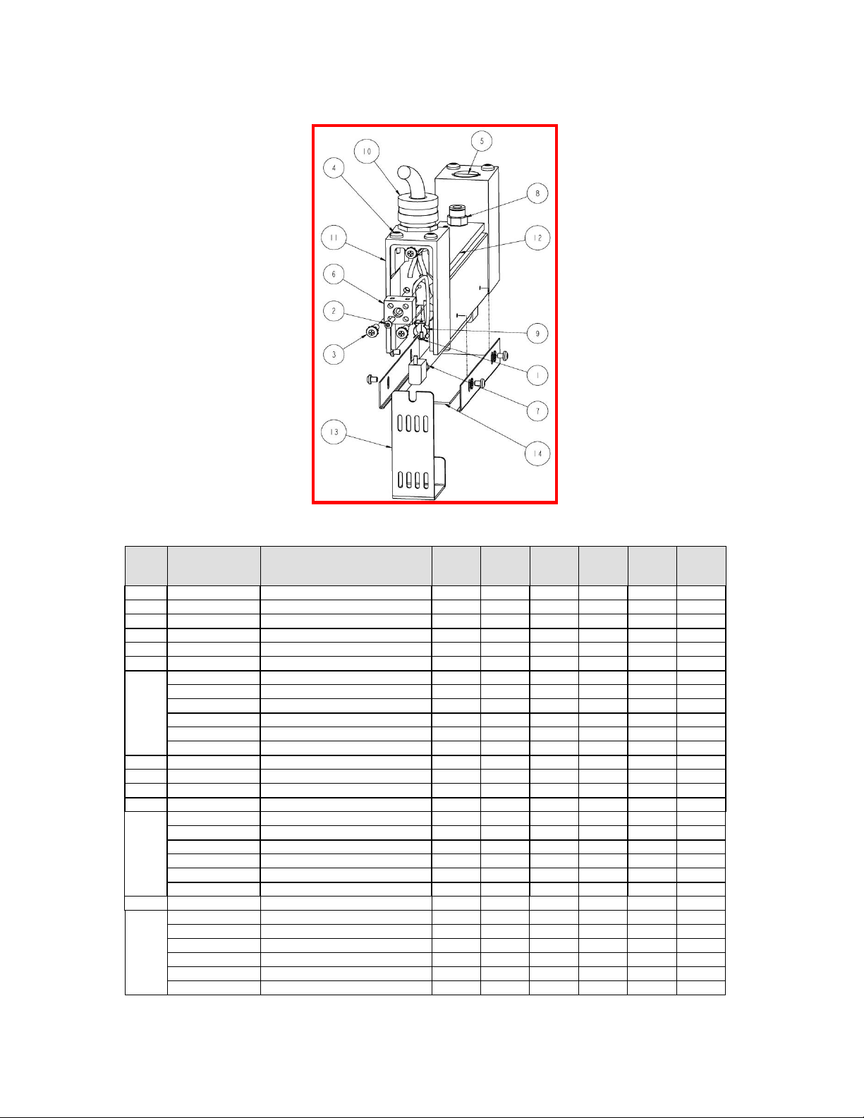
Section 7 – SPARE & REPLACEMENT PARTS
Figures 7-1. Model 5306B Parts Identification.
106837-001 Rev. 1 6-1
 Loading...