

Page 1
Instruction Manual
Infrared Strip Heater
Model 4185 StripIR
Publication No. 106991-001 Rev. 1
June 2010
Another quality product from:
7128 Shady Oak Road • Eden Prairie, MN 55344
(952) 949-9009 Fax (952) 949-9559
www.researchinc.com
Page 2

Dear Customer,
Thank you for purchasing the Model 4185 StripIR™. We believe it is the finest
system of its type and are confident you will think so too.
For technical assistance, training, replacement parts and assemblies, or any
other problems or questions, contact our Field Service specialists. They will do
everything they can to help you or will put you in touch with someone who can.
This instruction manual has been carefully prepared to ensure you get all the
capabilities out of your system we designed and built into it. To tell us how we
can make the system, our support of it, or this manual even more useful, we
invite you to call our product manager with your suggestions and
recommendations.
Additional copies of this manual are available at reasonable cost from our
Customer Service Department.
Once again, let us welcome you to the growing family of Research, Inc.
customers. We look forward to working with you in the future.
Sincerely,
Terry Nigon
President
Research, Inc.
Page 3

Section 1
Introduction
Features and Benefits………………………………………………… 1-2
Heater Description……………………………………………………. 1-2
Product Sizes…….……………………………………………………. 1-3
Lamps………...…..……………………………………………………. 1-3
Power Controller………….…………………………………………… 1-4
Section 2
Safety
General ………………………………………………………………… 2-1
Infrared Radiation…………………………………………………….. 2-1
High Temperatures…………………………………………………… 2-1
Electrical Safety ………………………………………………………. 2-1
Fire Safety……………………………………………………………... 2-2
Section 3
Assembly
Required Tools…………………………………………………………. 3-1
Reflector and Lamp Installation ……………………………………… 3-1
Exploded View.…………………………………………………………. 3-1
Section 4
Installation
Unpack and Check for Damage……………………………………... 4-1
Required Tools………….……………………………………………… 4-1
Mechanical Installation...………………………………………..……. 4-1
Heater Dimensions …….……………………………………………… 4-2
Wiring Power to Heater……………………………………………….. 4-3
Section 5
Maintenance
General………………………………..………………………………… 5-1
Lamp and Reflector Surface Maintenance………………………….. 5-1
Lamp Replacement…………………………………………………….. 5-1
Section 5
Product Information
Specifications….……………………..………………………………… 6-1
Ordering Information……………………….………………………….. 5-1
Accessories/Replacement Parts…….……………………………….. 5-1
Contents
Page 4
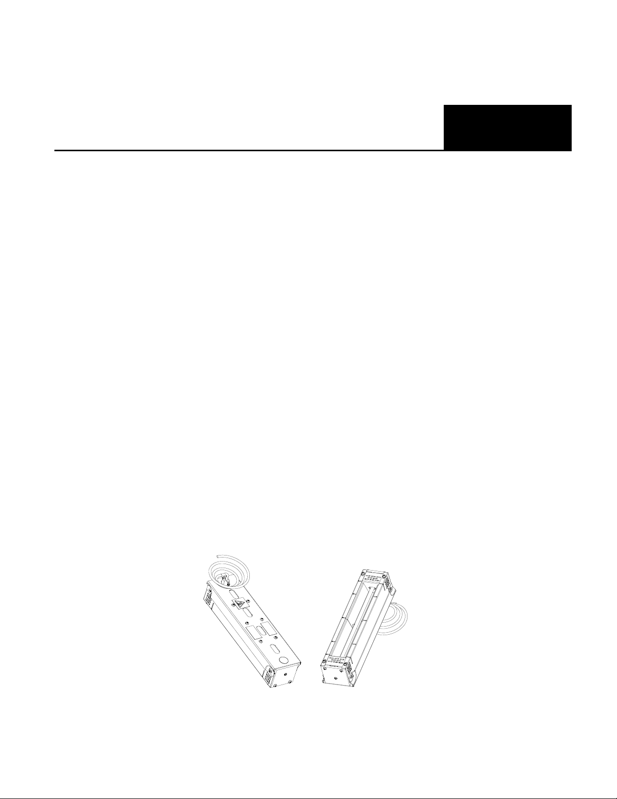
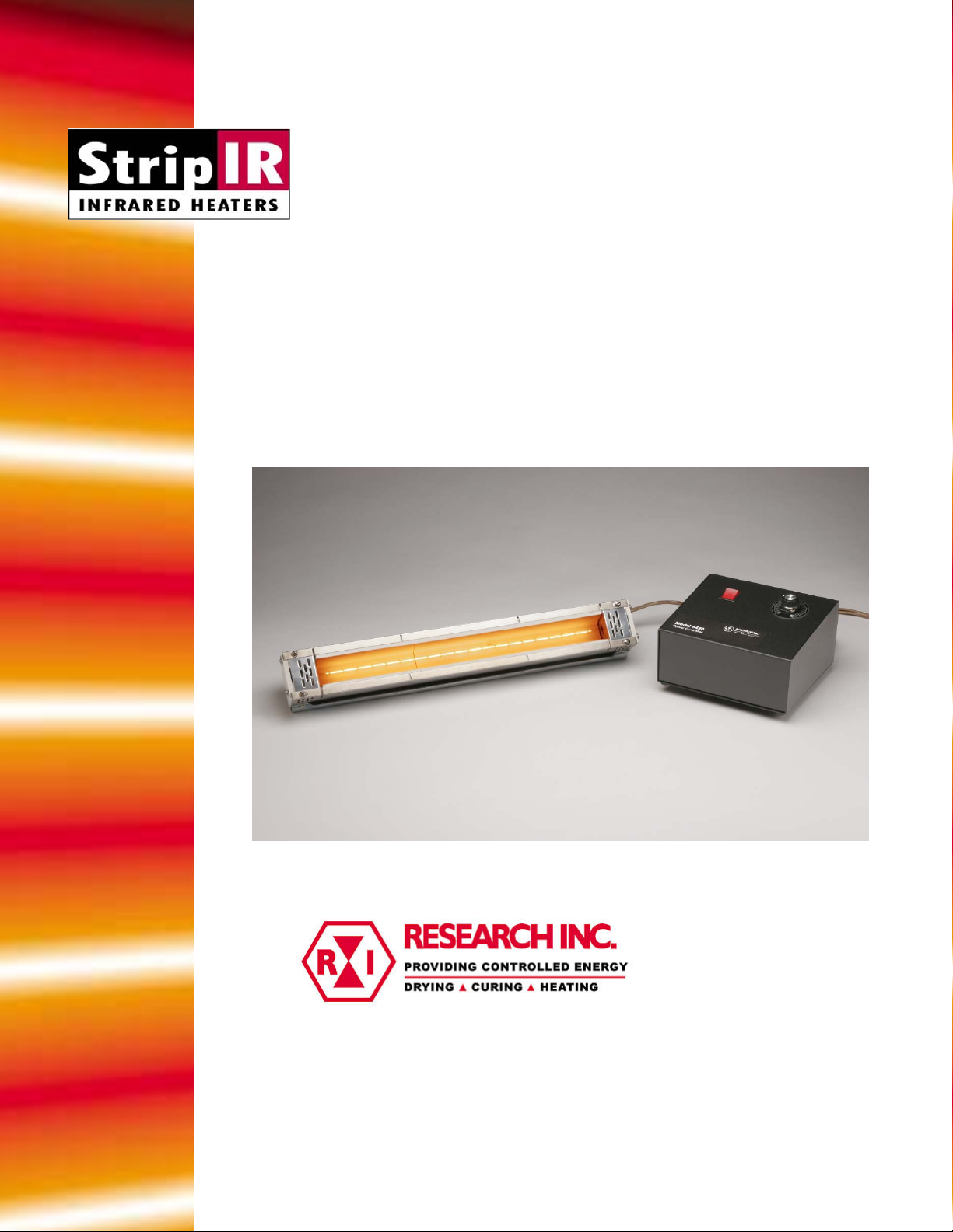
Figure 1-1: Model 4185 StripIR
Heater.
Section 1
Introduction
The Model 4185 StripIR infrared heater is a lamp and formed reflector heating system
that provides even heat distribution across a 1.7” wide strip. The Model 4185 heater uses
T-3, halogen lamps backed by a ceramic reflector to provide heat and offer the users
benefits of a high density heating solution.
The Model 4185 StripIR infrared heaters are designed for use in any application that
requires a clean, responsive, non-contact heat source. Some typical applications for the
heater are listed below:
• Curing epoxy
• Curing rubber coating on steel
• Drying and Curing Paint
• Drying and Curing adhesive
• Forming plastic
• Heating acrylic
• Laminating
• Preheating
• Reglossing
• Shrink Insulation
• Thermoforming
• Weld Stress Relief
1-1
Page 5

FEATURES AND
BENEFITS
HEATER
DESCRIPTION
• The lamps of these heaters heat up and cool down instantly in response to power
control signals.
• They reach 90 percent of full operating temperature within three seconds of a cold
start.
• The radiant energy dissipates to ten percent five seconds after the power supply is
disconnected.
• Localized heat focuses only on the desired area without heating the rest of the
product.
• The construction of these heaters, combined with air-cooling, allows them to
withstand continuous high temperature operation.
• Non-contact heat source does not come in contact with product being heated.
• The infrared energy emitted from these heaters can be adjusted to match the heating
requirements of a variety of applications.
• Repeatable results can be achieved for consistent process outputs.
• Integrated power controllers to control the operation of the heater.
• The ceramic reflector in the heater module is self-cleaning in most applications. This
feature provides both high efficiency and low maintenance cost.
Heater Module
The absorption/emission characteristics of the ceramic reflector surfaces in the Model
4185 heater module maintain a high surface temperature. The reflector material also
serves as a re-emitter of medium wave (3 to 4 microns) infrared energy. This can be
beneficial in many processes depending on the absorptive properti es of the material
being heated.
Ceramic Reflector
The ceramic reflector provides heat by re-emitting medium wave and short-wave energy.
Mounting
The back of the Model 4185 has six 10-32 NF threaded holes for mounting purposes.
Product Temperatures
The maximum work-piece temperature depends upon a number of conditions: the ability
of the work-piece to absorb radiant energy, the amount of heat loss, and the applied
voltage to the heater emitter. For continuous heating processes, the maximum workpiece temperature should be less than 1300°F (704°C).
Heat Flux Densities
The Model 4185 can generate as much as 100 watts per linear inch (3.9 watts per mm).
Dissipated power for the heaters varies with heated length and is listed in Specifications.
Heat flux density is a product of the lamp type, applied voltage, and distance between the
lamp and the target surface.
1-2
Page 6
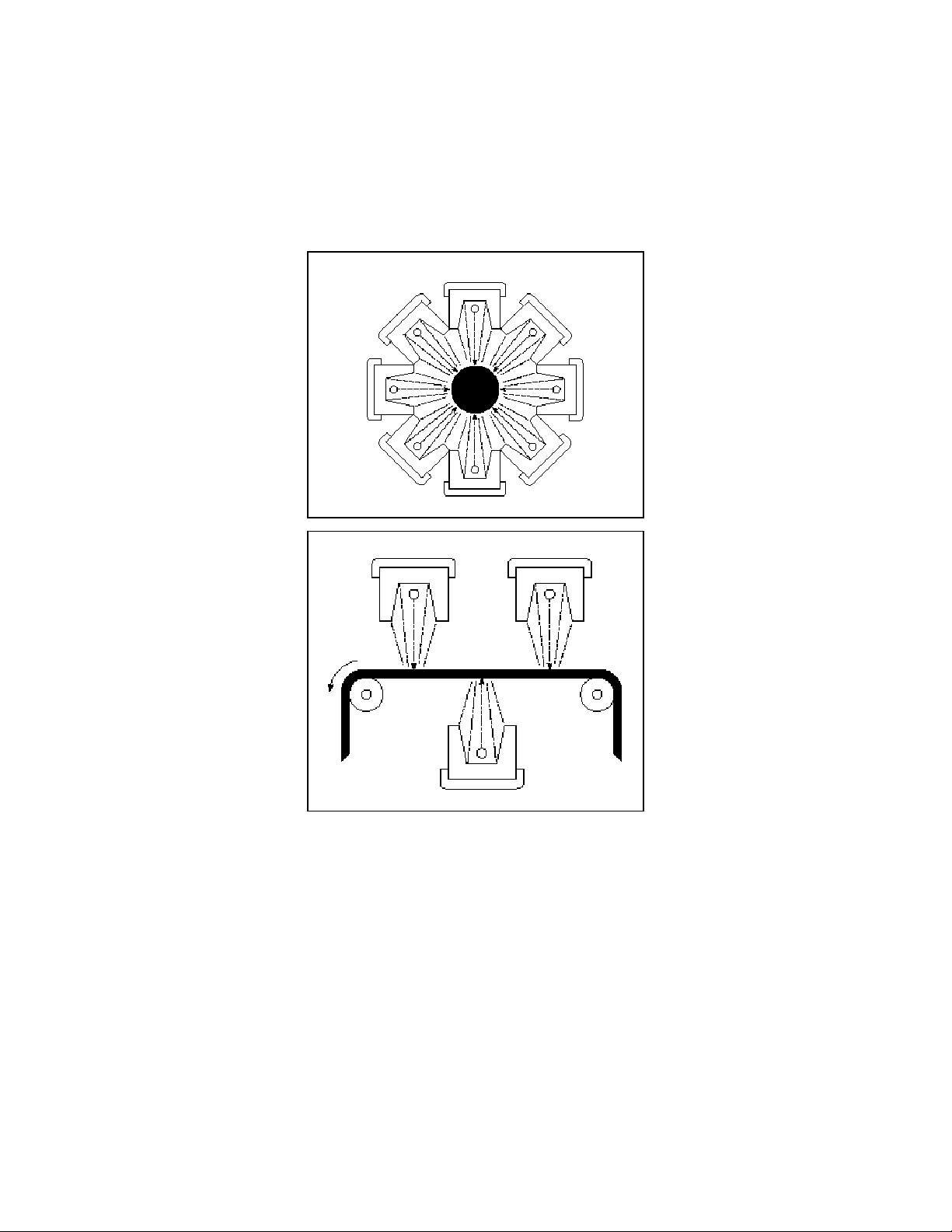
Figure 1-2: Cylindrical Heating
Figure 1-3: Web Drying
Product Sizes
A strip 1.7 inches in width and length from 5 to 38 inches (43 by 965 mm) can be heated
with a single Model 4185. Mounting two or more heaters side-by-side can create different
heated areas. For example, Figure 3 shows eight heaters installed cylindrically to provide
high heat concentration on work-piece objects. Heating efficiency is highest on objects 1
inch or larger. Figure 4 shows three heaters installed to provide heat to a moving web of
material. Additional heaters could be used in similar applications requiring greater heat
flux density.
Lamps
The Model 4185 utilizes high intensity, short wave tungsten lamps. The tungsten emitter
in the lamps has an operating temperature of up to 4000°F (2205°C) with a spectral
energy peak wavelength of 1.15 microns. Each heater requires one lamp to operate. The
Model 4185 will heat a strip that is 1.7 inch (43 mm) wide and is available in heated
lengths of 5, 10, 16, 25 and 38 inches (127, 254, 406, 635 and 965 mm). Heated lengths
should be at least 20% larger than work-piece.
1-3
Page 7
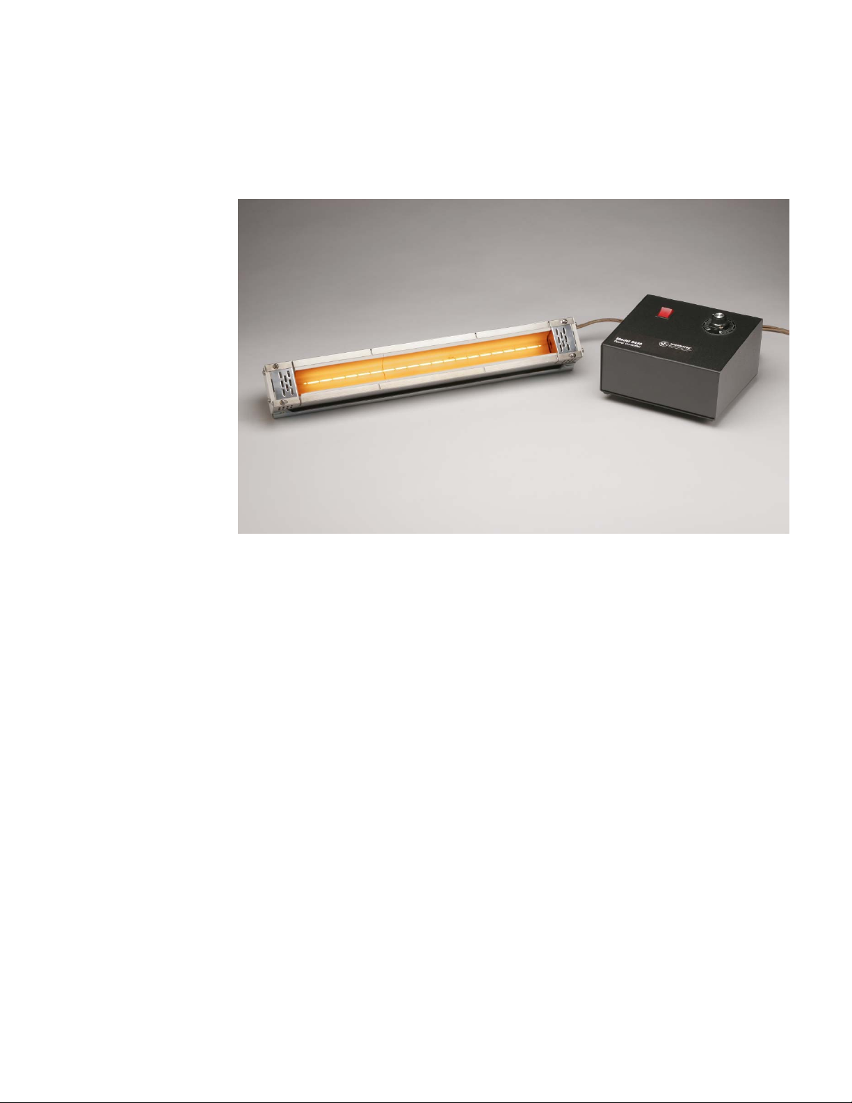
Figure 1-4: Model 4185 with
Power Controller
Power Controller
The Model 4185 heater comes with the Research, Inc. Model 5420 SCR Power
Controller. A separate instruction manual for the Power Controller is included with the
heater.
1-4
Page 8
GENERAL
INFRARED
RADIATION
HIGH
TEMPERATURES
ELECTRICAL
SAFETY
Section 2
Safety
The Model 4185 Strip Heater is designed for safe operation. Nevertheless, installation,
maintenance and operation of the heater can be dangerous for a careless operator or
maintenance person. For your safety and the safety of others, please read the
instructions in this INSTRUCTION MANUAL and follow these safety practices that will
help to prevent accident or injury.
CAUTION!
Continuous exposure to high intensity infrared radiation at close proximity could be
harmful to eyes or skin. Although infrared lamps are not emitting ultra violet
electromagnetic radiation, harmful burns could still result if an operator is in close
contact with lamps being operated at high intensity.
Because of the brilliant light emitted by infrared lamps at full intensity, it is
recommended that the eyes be shielded from the glare if observing the lamps or
radiant heat chamber for an extended period of time. Use suitable shaded lenses or
dark glasses.
Parts of the heater may exceed 500°F (260°C). Contact with the lamps, reflectors, or
metal parts near the lamps may cause severe BURNS.
WARNING!
NEVER place hands under the heating elements.
ALWAYS allow heating element to cool at least 5 minutes before touching the
lamps or adjacent parts.
There is danger of electrical shock when servicing the heater.
CAUTION!
Observe that all applicable local and national electrical codes are met and a safe
electrical ground system is installed before attempting to operate the heater. Refer
to the Section 3 for proper installation procedures.
2-1
Page 9

FIRE SAFETY
WARNING!
ALWAYS disconnect the external power lines prior to servicing the heater.
ALWAYS disconnect the power lines AND any optional interlock circuits before
installing or changing lamps.
NEVER operate the heater with the heater end covers removed.
1. Obey the same fire-safety rules you observe when you work with hot plates, high
intensity infrared heaters, propane or acetylene torches, soldering irons, and
other equipment that gets very hot.
2. Remove all solids, liquids, and gases that burn easily from the area around the
heater.
3. Know where the nearest fire extinguisher is located and how to use it.
4. Know how to put out fired from all the types of material near the Model 4185
Heater.
2-2
Page 10

UNPACK AND
CHECK FOR
DAMAGE
REQUIRED TOOLS
REFLECTOR
AND LAMP
INSTALLATION
Section 3
Assembly
Remove the Model 4185 heater from its shipping container and associated packaging.
Check the entire unit for any potential damage due to shipping. In the unlikely event
damage has occurred, keep all shipping containers and materials and file a damage
claim with the shipping company that delivered the heater.
• Phillips Screwdriver
• Pliers
• Wire Stripper
NOTE:
The Reflectors and Lamp are shipped separately and must be installed prior to operation.
Refer to Figures 3-1 Reflector and Lamp Assembly operations.
1. Remove both Ceramic End Covers, item 1, from both End Reflector assemblies, item
4.
2. Remove End Reflector assemblies, item 4, from Heater Housing, item 2, on the end
opposite Power Cord, item 19.
3. Slide Reflectors, item 3 into Heater Housing, item 2.
4. Reassemble End Reflector, item 4.
CAUTION!
Wear soft, clean, oil-free flannel or plastic gloves when handling halogen, quartz
lamps. Oils and contaminants are readily transmitted to the quartz by unprotected
hands and can cause premature lamp failure.
5. From the end of the assembly insert the Lamp, item 18, through the End Reflector
openings
6. Trim approximately 4“ off each Lamp Lead then strip.25” of insulation off each Lamp
Lead.
7. Insert Lamp Lead into Terminal Blocks, item 17, to make connections to power
wiring. Repeat at other end.
8. Reassemble End Covers, item 1.
3-1
Page 11
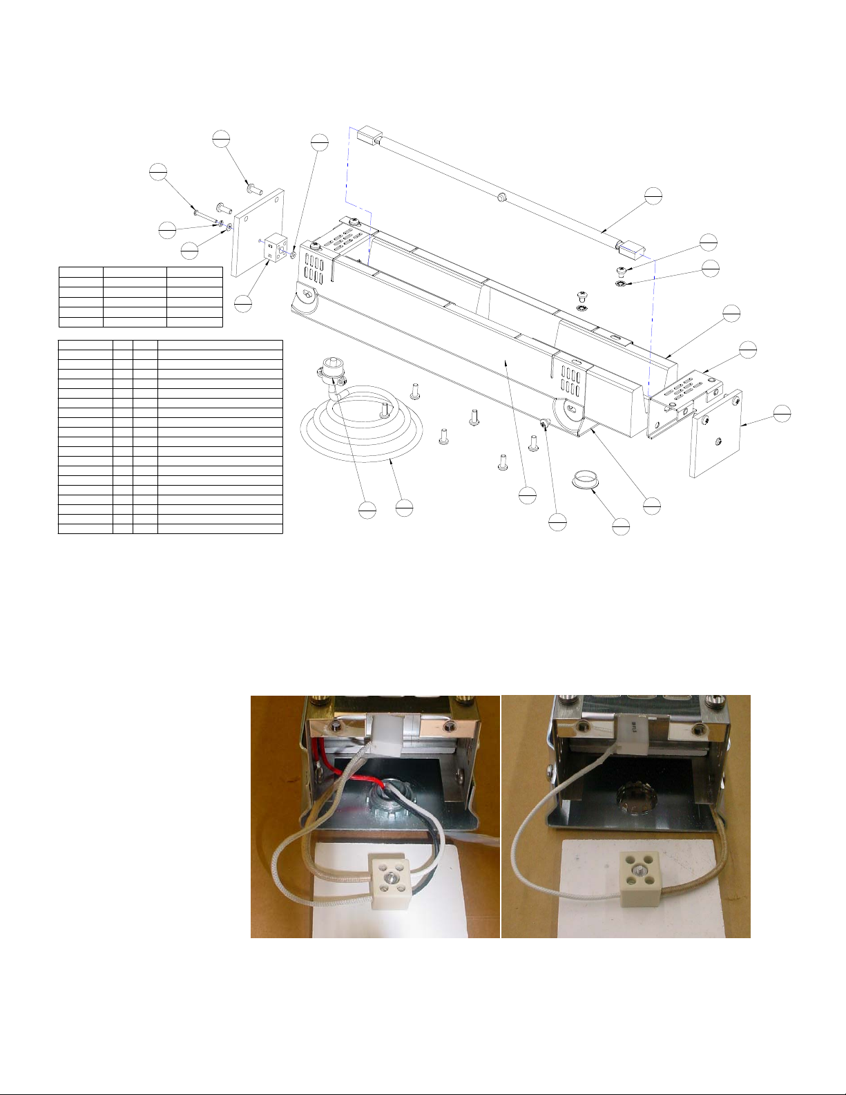
Figure 3-1: Reflector and
Lamp Assembly
8
10
6
2
11
2
9
2
38 INCH42.504185-38
25 INCH29.504185-25
16 INCH20.504185-16
10 INCH14.504185-10
5 INCH9.504185-05
DESCRIPTIONOVERALL LENGTHMODEL NO.
COMPONENT NO. QTY ITEM DESCRIPTION
037193-000 2 1 COVER-END 4184
***
037194-004 1 2 FAB-COVER 4184 20.50 LG
037195-004 2 3 REFL-4184-10
***
037197-000 2 4 FAB/ASSY-END REFLECTOR
037603-002 1 5 FAB-COVER SAFETY 4184-16
***
054979-027 2 6 SCRW-PH 4-40X1 SST PH
054979-105 8 7 SCRW-PH 10-32X1/4 SST PH
054979-123 10 8 SCRW-PH 10-32X.5 PH SS SEMS-IN
055029-002 2 9 WASHER-FLAT #4 SST
055307-017 2 10 NUT-HEX 4-40 SST
055310-017 2 11 WASHER-SPLIT,#6,SST
055455-011 4 12 WASHER-LOCK #10 INT ZI
055729-004 1 13 PLUG-BUTTON,7/8 DIA.
060512-001 1 14 STRAIN RELIEF-BUSHING
095180-006 2 15 LABEL-THERMAL/BARCODE (2X1)
098901-001 1 16 LABEL-HOT SURFACE UL IEC 5041
100571-001 2 17 TERMINAL BLOCK CERAMIC 2P 10A
***
103390-004 1 18 LAMP-QIH240-2000/V CER.END
106690-002 1 19 CABLE-14/3 TEFLON JACKET 200°C
*** DENOTES PART NUMBERS LISTED ARE FOR MODEL 4185-10.
CONSULT FACTORY FOR PART NUMBER CORRESPONDING TO
YOUR MODEL.
10
2
18
1
7
8
12
4
17
2
2
19
14
1
1
1
7
REF
5
1
13
1
3
2
4
2
1
2
3-2
Page 12
TOOLS REQUIRED
MECHANICAL
INSTALLATION
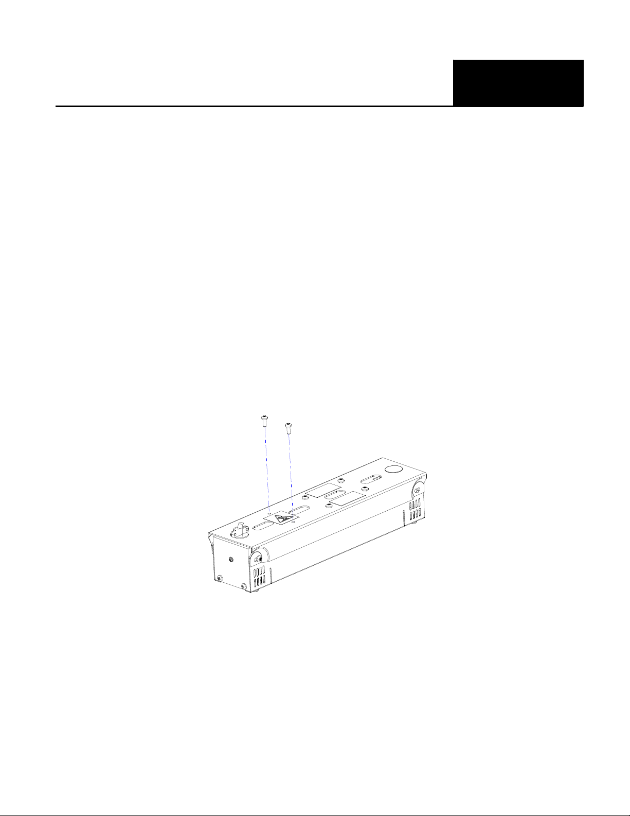
Figure 4-1: Typical
Installation for Model 4185
Heater
Section 4
Installation
• Phillips Screwdriver
NOTE:
Refer to Figures 4-1 Typical Installation.
Refer to Figure 4-2 Mounting Dimensions.
As shown in Figure 4-1, six 10-32 x 1/2 inch screws are provided on the top of the Model
4185 heater for mounting purposes. The heater can be attached directly to a suitable
frame structure or mounting brackets using these six screws. Mount the heater so that
the intended target absorbs the generated infrared energy yet not so close that the heater
touches the target. The heater should be mounted so that each end cover may easily be
removed for lamp installation.
Multiple Model 4185 heaters can be mounted side-by-side to form large heating arrays.
4-1
Page 13
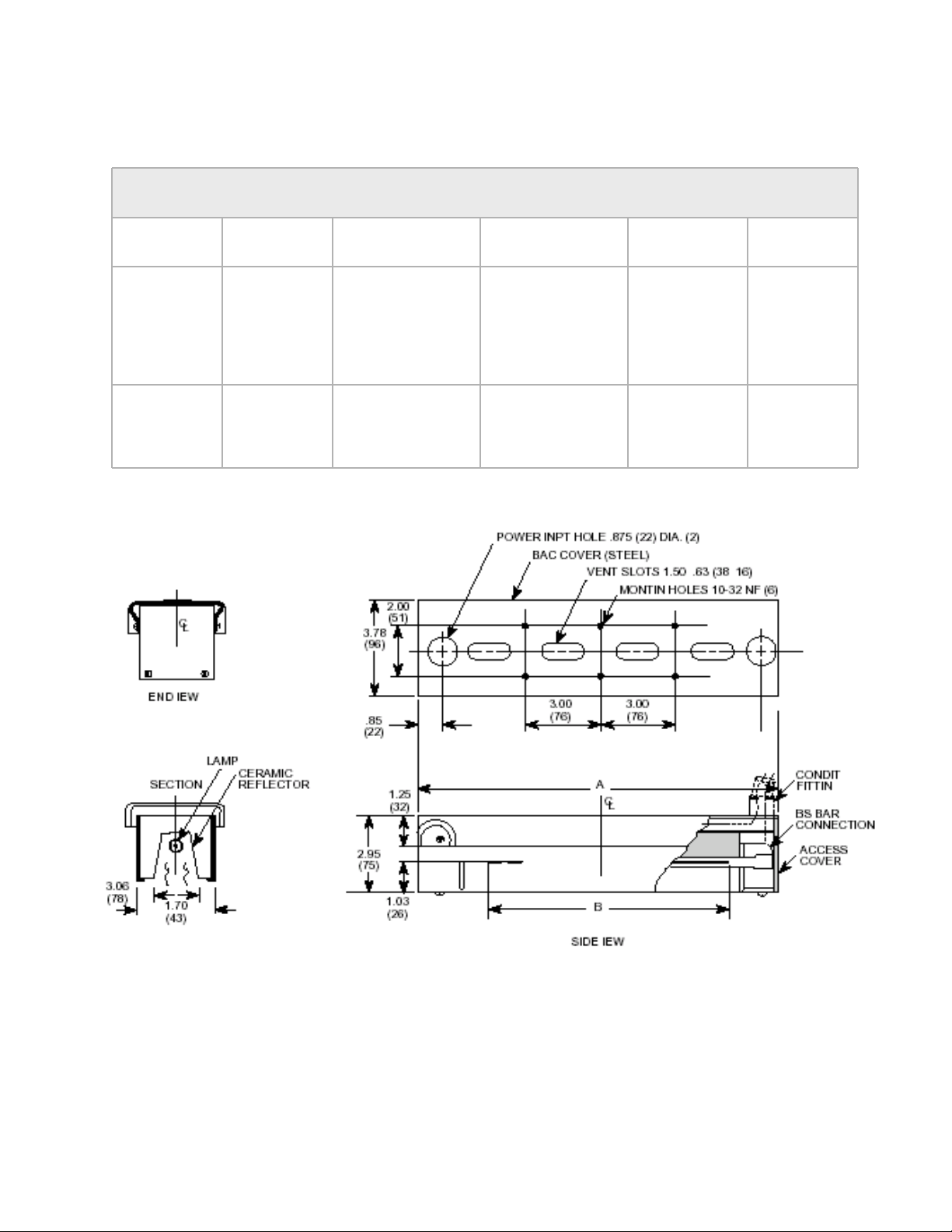
Figure 4-2: Mounting
Dimensions for Model 4185
Heater
Dimension
A
Overall
Length
Inches (mm)
B Lighted
Length
Inches (mm)
DIMENSIONS STRIP IR 4185
4185-25 4185-16 4185-10 4185-05
4185-38
42.5 (1080) 29.5 (749) 20.5 (521) 14.5 (368) 9.5 (241)
25 (635) 16 (406) 10 (254) 5 (127)
38 (965)
4-2
Page 14

WIRING POWER
TO HEATER
All electrical wiring from the Model 4185 to the Model 5420 SCR Power
Controller is included on Model 4185 units. Refer to Model 5420 SCR Power
Controller Instruction Manual for further wiring details.
4-3
Page 15
Maintenance
Section 5
GENERAL
LAMP AND
REFLECTOR
SURFACE
MAINTENANCE
LAMP
REPLACEMENT
Periodic inspection and removal of dirt and contaminants will ensure that equipment can
be operated safely.
In dirty environments or heating operations the lamps may become contaminated with
smoke, dust, fingerprints or other foreign matter. When this occurs it is recommended
that the lamp be cleaned. Doing so will extend the life of the lamp and improve the
heater’s overall performance. Use the following procedure:
WARNING!
Disconnect the power cable from the power source and allow the heater to cool
before continuing.
CAUTION!
Wear soft, clean, oil-free flannel or plastic gloves when handling quartz lamps. If
skin oils come in contact with the quartz tube, the lamp will fail prematurely.
1. With a soft, dry cloth or tissue, wipe the residue from the lamps. Household strength
ammonia can be used to clean the lamps if necessary.
The ceramic reflector is a high temperature material with unlimited life and is essentially
self-cleaning.
CAUTION!
Wear soft, clean, oil-free flannel or plastic gloves when handling quartz lamps. If
skin oils come in contact with the quartz tube, the lamp will fail prematurely.
1. Remove both end covers from the Model 4185 by removing the two screws from
each end cover using the Phillips screwdriver.
2. Disconnect lamp leads from terminal blocks.
3. Grasp lamp end and pull the lamp out of heater.
4. Feed one end of the new lamp (wire first) into the lamp slot in end reflector, through
the heater, and into the lamp slot on the heater’s opposite end.
5. Connect lamp leads to terminal blocks.
6. Reinstall both end covers, insert all four end cover screws, and ‘hand tighten’ each
screw using the Phillips screwdriver.
5-1
Page 16

600
00
0
olt
(5.8)
Product Information
Specification
MODEL SPECIFICATIONS 4185
Section 6
Weight lb (kg)
Rated Voltage
Part to Order
Power at
Lamp
Optical
103390-001
4185-05-500
4185-101000E
1.0 KW
103390-003
Clear
4185-101
6-1
1.6 KW
103390-005
Clear
4185-161
4185-25 4185-16 4185-10 4185-05 Specifications
8.4 (3.8) 5.4 (2.6) 3.3 (2.6) 2.0 (0.91)
480 Volt 240 Volt 240 Volt 120 Volt
2.5 1.0 KW 0.5 KW
103390-007 097771-001
Clear EZ eye Clear
4185-25-2500
4185-38
12.8
480
V
3.8
103390-010
Clear
4185-38-3800
Page 17

Ordering Information
Product Description - 5 inch Strip heaters (500 watt)
4185-05-500-01-00 4185-05 with Model 5420-120 controller (includes potentiometer)
4185-05-500-02-00 4185-05 with Model 5420E-120 controller (includes potentionmeter and timer)
4185-05-500-03-00 4185-05 with Model 5420mA-120 controller (includes 4-10 mA input control)
Product Description - 10 inch Strip heaters with EZ eye lamp (1000 watt)
4185-10-1000E-01-00 4185-10 with Model 5420-120 controller (includes potentiometer)
4185-10-1000E-02-00 4185-10 with Model 5420E-120 controller (includespotentionmeter and timer)
4185-10-1000E-03-00 4185-10 with Model 5420mA-120 controller (includes 4-10 mA input control)
Product Description - 10 inch Strip heaters (1000 watt)
4185-10-1000-01-00 4185-10 with Model 5420-240 controller (includes potentiometer)
4185-10-1000-02-00 4185-10 with Model 5420E-240 controller (includes potentionmeter and timer)
4185-10-1000-03-00 4185-10 with Model 5420mA-240 controller (includes 4-10 mA input control)
Product Description - 16 inch Strip heaters (1600 watt)
4185-16-1600-01-00 4185-16 with Model 5420-240 controller (includes potentiometer)
4185-16-1600-02-00 4185-16 with Model 5420E-240 controller (includes potentionmeter and timer)
4185-16-1600-03-00 4185-16 with Model 5420mA-240 controller (includes 4-10 mA input control)
Product Description - 25 inch Strip heater with EZ Eye lamps (2500 watt)
4185-25-2500E-01-00 4185-25 with Model 5420-240 controller (includes potentiometer)
4185-25-2500E-02-00 4185-25 with Model 5420E-240 controller (includes potentionmeter and timer)
4185-25-2500E-03-00 4185-25 with Model 5420mA-240 controller (includes 4-10 mA input control)
Product Description - 25 inch Strip heaters (2500 watt)
4185-25-2500-01-00 4185-25 with Model 5420-480 controller (includes potentiometer)
4185-25-2500-02-00 4185-25 with Model 5420E-480 controller (includes potentionmeter and timer)
4184-25-2500-03-00 4185-25 with Model 5420mA-480 controller (includes 4-10 mA input control)
Product Description - 38 inch Strip heaters (3800watt)
4185-38-3800-01-00 4185-38 with Model 5420-480 controller (includes potentiometer)
4185-38-3800-02-00 4185-38 with Model 5420E-480 controller (includes potentionmeter and timer)
4185-38-3800-03-00 4185-38 with Model 5420mA-480 controller (includes 4-10 mA input control)
MODEL 4185
6-2
Page 18

A
A
A
,
p
,
p
)
Accessories/Replacement Parts
103390-003
103390-007
037195-003
037195-008
037195-003,-008
037195-007
-008
Re
lacement Lamps (all lamps sold in pairs
500 watt, 103390-001
5 inch
10 inch, 1000 watt
16 inch, 1600 watt 103390-005
25 inch 2500 watt
38 inch, 3800 watt 103390-010
Re
lacement Reflectors
05 inch length (1 per heater)
10 inch length (1 per heater)
16 inch length (1 each per heater)
25 inch length (Qty. 1 -007 and Qty. 2 -008 per heater)
38 inch length (Qty. 1 -003 and Qty. 3 -008 per heater) 037195-003,-008
Heater Modules
4184-05-500 Heater Module4185-05-500
4185-10-1000 Heater Module4185-10-1000
4185-16-1600 Heater Module4185-16-1600
4185-25-2500 Heater Module4185-25-2500
4185-38-3800 Heater Module4185-38-3800
120 volt Power Controllers
Model 5420-120 Power Controller5420-120
Model 5420E-120 Power Controller5420E-120
Model 5420m
240 Volt Power Controllers
Model 5420-240 Power Controllers5420-240
Model 5420E-240 Power Controllers5420E-240
Model 5420m
480 Power Controllers
Model 5420-480 Power Controllers 5420-480
Model 5420E-480 Power Controllers5420E-480
Model 5420m
6-3
MODEL 4185
-Power Controller5420mA-120
-240 Power Controllers5420mA-240
-480 Power Controllers5420mA-480
Page 19

Accessories/Replacement Parts continued
4184/4185 Ceramic Reflectors Replacement Part Numbers
Heater Size Old Reflector Part # Length Qty. New Reflector Part # Length Qty.
5 037195-003 6.0” 1 037195-003 6.00” 1
10 037195-004 5.5” 2 037195-008 11.0” 1
16 037195-001 5.66” 3 037195-008
037195-003
25 037195-002 6.5” 4 037195-008
037195-007
38 037195-002 6.5” 6 037195-008
037195-003
6-4
11.0”
6.0”
11.0”
4.0”
11.0”
6.0”
1
1
2
1
3
1
 Loading...