

Page 1
Model 4069P User’s Manual
Publication #: 107663-001 Rev. _
Feb. 2009
Another quality product from:
7128 Shady Oak Road, Eden Prairie, MN 55344
Phone: (952) 949-9009 Fax: (952) 949-9559
E-mail: [email protected]
www.researchinc.com
Page 2

Model 4069P ProfileIRTM User Manual Contents
Section page
INTRODUCTION
General Description 1
Standard Features 1
Optional Features
2
SAFETY
General 3
Gas Shock 3
High Temperatures 3
Electrical 3
SPECIFICATIONS
Specifications 4
Dimensions 6
INSTALLATION
Wiring 8
Control Connections 10
Remote Interlock Switch 10
Remote Fast Stop 10
Water Connections 10
Air Connections
10
OPERATION
Main Disconnect Switch 11
Operator Control Panel 12
Panel View Terminal 13
Main Screen 14
Recipe Screen
Alarms Screen 18
Options Screen
16
20
MAINTENANCE AND
TROUBLE SHOOTING
Routine Maintenance 22
Lamp Removal, Replacement and Installation
Split Quartz Cleaning and Replacement
22
24
Page 3

Model 4069P ProfileIRTM User Manual Contents
Cleaning the Reflectors 25
Removing the Reflectors 26
Trouble-Shooting 28
Spare Parts
30
Page 4

Model 4069P ProfileIRTM User Manual Introduction
General
Description
Standard
Features
Introduction
The Model 4069P ProfileIR curing System uses high intensity infrared lamps and polished
aluminum reflectors to deliver heat precisely where it is needed for many curing and
drying applications on extrusion lines. It can be used effectively to provide a surface cure
to rubber extrusions, dry adhesives and coatings on rubber or metal, and provide in process
curing between layers of multi layer cable. Depending on the model selected, diameters as
small as ¼ inch or a large as 4 inches can be processed. This system includes, along with
the Model 4069 ChamberIR heater, an operator interface pedestal with a PanelView 400+
terminal, a split quartz liner, height adjustment with plus/minus 15 degrees of tilt off
horizontal, and convenient connection points for power, water and air. Optional features
that can be ordered with the unit include an optical pyrometer to monitor product
temperature, product motion sensing to shut power down if the line brakes, and an air
nozzle kit to provide forced air inside the heating chamber to increase efficiencies in
curing and drying.
The single chamber models are an efficient solution for most applications and the dual
chamber models provide additional product support to allow fragile product to run through
the system without breaking or drooping
Typical applications for the Model 4069P include:
Surface cure on rubber extrusion
Drying adhesives and coatings on rubber or metal
Soften and Cure between multi-layer extrusions
Cast and hold the shape extrusion
Flash cure coatings between operations
Heater Module –A circular array of individual parabolic polished aluminum reflectors
direct the infrared energy generated by the quartz lamps towards the center axis of the
heater. Each heater houses either 12 or 18 reflectors, depending on the model. The 12
reflector model accepts product sizes up to 2 inches in diameter while the 18 reflector
model accepts products up to 4 inches in diameter. Heated lengths of 10, 16, 25, and 38
inches (254, 406, 635, and 965 mm) are offered for the Model 4069P. For applications
prone to product sagging a dual heater system with two 10” heated length chambers and an
intermediate product support between them is available. The chamber’s clamshell design
offers easy access for liner cleaning and lamp servicing by simply releasing the latches on
the front of the chamber and lifting the upper half. Gas springs are provided to assist with
the left gas spring having an integral extension lock. The factory installed ceramic end
seal T3 style lamps provide precise levels of power to the product in the chamber. The
lamps generate infrared energy at a peak wavelength of 1.2 microns at rated voltage. This
wavelength is commonly known as short wavelength or NIR, (Near Infrared). The lamps
reach 90% of full operating temperature within three seconds of a cold start. Radiant
energy is dissipated to 10% five seconds after power is shut down. Additional lamps can
be ordered separately from the heater.
Research, Inc.
1
Page 5

Model 4069P ProfileIRTM User Manual Introduc tion
Standard
Features
Optional
Features
Heater Positioning – The chamber is mounted to lifts at each end allowing for variations
on product elevation. Each lift can operate independently allowing for up to 15° off
chamber tilt. This can be useful when product sagging is occurring.
Water Cooling – Each reflector is designed with an internal coolant passageway to allow
coolant to flow through its entire length during operation. Water lines run from the fittings
on the base of the cart to the heater. Adequate cooling water is required during operation
of the Model 4069E. Required cooling-water flow rates are listed in Specifications.
Air Cooling – A cooling fan is designed into the Model 4069 housing and provides
ambient airflow through the heater body. This airflow helps to prevent air-borne
contamination from depositing on the reflector surfaces. It also provides cooling to the
quartz halogen lamp end seals.
Split Quartz Liner – A split quartz liner is included with the Model 4069 and provides
contamination protection for the aluminum reflectors. When installed in the heater, the
quartz liner protects the aluminum reflector and lamp from contaminants released in the
heating process, resulting in maximum efficiency of the heater.
Operator Interface – The operator interface includes a PanelView 400+ terminal for
controlling the system; lift control switches and a fast stop.
Power Control Cabinet − A NEMA 12 cabinet containing components to accurately
control power to the system.
Product Motion Detection – An optional low torque roller providing rotational feedback
can be positioned at either end of the chamber to signal product stoppage. If no signal is
detected the system will shut down power to the chamber thus reducing the incidence of
the product burning in the chamber. When motion is restored, the lamp voltage will be reapplied to the previous value.
Air Curing Nozzles – Optional twin air curing nozzles can be attached to the input end of
the heater. These nozzles force air down the length of the quartz liner and provide a
convective component to the curing process. This option includes a fitting for house air, a
filter and regulator in addition to the nozzles.
Exhaust Hood – An optional exhaust hood attaches to the exit end of the single chamber
system or between chambers on a dual chamber system to collect smoke and gasses given
off during heating the process. 3 inch diameter is used all 12R units and a 4” diameter is
used on all 18R units.
Pyrometer – The optional pyrometer is useful for monitoring product temperature in
sensitive areas. The mounting bracket provides multiple sensing positions for full product
coverage. This option includes a fitting for house air, a filter and regulator in addition to
the pyrometer.
Booster Pump – An optional booster pump is available when plant water pressure is too
low to provide adequate flow rate for proper cooling of the chamber. Pump will raise the
water pressure up-to 50 PSI
Research, Inc. 2
Page 6
Model 4069P ProfileIRTM User Manual Safety
Safety
General
Gas Shock
High
Temperatures
Electrical
The Model 4069P heater is designed for safe operation. Nevertheless, installation,
maintenance, and operation of the heater can be dangerous for a careless operator or
maintenance person. For your safety and the safety of others, read the instructions in this
instruction manual and follow these safety practices to help prevent accident or injury.
INFRARED RADIATION - CAUTION!
intensity infrared radiation at close proximity could be harmful to eyes or skin. Although
infrared lamps emit negligible ultra violet electromagnetic radiation, harmful burns can
still result if an operator is in close contact with lamps being operated at high intensity.
Because of the brilliant light emitted by infrared lamps at full intensity, it is recommended
that eyes be shielded from the glare if observing the lamps for an extended period of time.
Use suitable shaded lenses or dark glasses.
A latching shock is installed on the left side of the model 4069 heater. The latch will
prevent the heater from closing should the gas strut fail. When closing the heater pull the
knob to release the latch while closing. Failure to release latch can cause damage to the
heater if forced closed.
Parts of the heater may exceed 500°F (260°C). Contact with the lamps, reflector, or metal
parts near the lamps may cause severe burns.
WARNING!
NEVER place hands under or in front of the heating elements.
ALWAYS allow heating element to cool at least three minutes before touching the lamps
or adjacent parts.
There is danger of electrical shock when servicing the heater.
CAUTION! Observe all applicable local and national electrical codes and ensure that
a safe electrical ground system is installed before attempting to operate the heater. Refer
to the Section 5 for proper installation procedures.
WARNING!
ALWAYS disconnect the external power lines prior to servicing the heater.
ALWAYS disconnect the power lines AND any optional interlock circuits before
installing or changing lamps.
NEVER operate the heater with end covers removed.
Continuous exposure to high-
Research, Inc. 3
Page 7
Model 4069 ProfileIRTM User Manual Specifications
Specifications
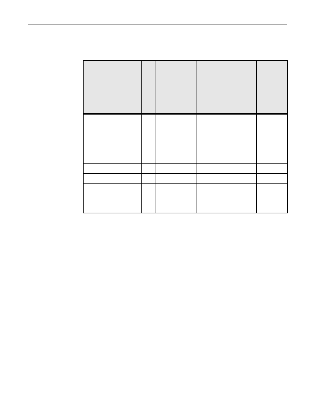
4069P-12R-10L-12kW-480V
4069P-12R-16L-19kW-480V
4069P-12R-25L-30kW-480V
4069P-12R-38L-46kW-480V
4069P-18R-10L-18kW-480V
4069P-18R-16L-29kW-480V
4069P-18R-25L-45kW-480V
4069P-18R-38L-68kW-480V
Model Number*
4069P-12R-10L-DUAL-
18kW-480V
4069P-18R-10L-DUAL-
36kW-480V
* Recommended maximum product diameter for 12-reflector models is two inches.
Recommended maximum product diameter for 18-reflector models is four inches.
** Stated flow rates are for each of two flow paths.
*** Maximum inlet water temperature not to exceed 100° F (37°C)
Lamp Lighted Length,
10
(254)
16
(406)
25
(635)
38
(965)
10
(254)
10
(254)
16
(406)
25
(635)
38
(965)
10
(254)
Inches (mm)
Lamp Wattage
1000
1600
2500
3800
1000
1000
1600
2500
3800
1000
Lamp Type
QIH2401000RI2
QIH2401600RI2
QIH4802500RI2
QIH4803800RI2
QIH2401000RI2
QIH2401000RI2
QIH2401600RI2
QIH4802500RI2
QIH4803800RI2
QIH2401000RI2
Lamp Part Number
103390-
003
103390-
005
103390-
007
103390-
010
103390-
003
103390-
003
103390-
005
103390-
007
103390-
010
103390-
003
Wattage Heater, kW
Lamp Rated Voltage
240 12.0 1.2 (4.5) 10
240 19.2 1.8 (6.9) 16
480 30.0
480 45.6
240 24 2.4 (9) 20
240 18.0 1.7 (6.5) 15
240 28.8 2.7 (10.2) 29
480 45.0
480 68.4
240 36 3.4 (13) 30
(LPM)
***Water Flow GPM
2.8
(10.6)**
4.2
(15.9)**
4.2
(15.7)**
3.1
(11.9)**
Heater @ Required
Pressure Drop Through
31
63
61
37
Water Flow, psi +/- 5psi
(227)
(234)
(243)
(256)
(261)
(237)
(249)
(267)
(290)
(281)
Total Weight, Pounds (kg)
501
515
535
564
575
523
550
588
639
619
Research, Inc. 4
Page 8

Model 4069 ProfileIRTM User Manual Specifications
2 Inch Diameter ProfileIR Model 4069P
Single Chamber2 Inch Diameter Profile
Dual Chamber 2 Inch Diameter Profile
Power Generated
Model
4 Inch Diameter ProfileIR Model 4069P
Single Chamber 4 Inch Diameter Profile
4069P-12R-38L 4069P-12R-25L 4069-12R-16L 4069P-12R-10L Model
45.6kW 30kW 19.2kW 12kW Power Generated
480 volt 3 phase 480 volt 3 phase 240 volt 3 phase 240 volt 3 phase Voltage
55 amp 36 amp 46 amp 29 amp Max Current
564 lb (256 kg) 535 (243 kg) 515 lb (234 kg) 501 lb (227 kg) Weight *
103390-010 103390-007 103390-005 103390-003 Lamp Type
4.2 gpm (15.9 lpm) 2.8 gpm (10.6 lpm) 1.8 gpm (6.8 lpm) 1.2 gpm (4.5 lpm) Water Flow Requirement
4069P-12R-10L-Dual
25Kw
480 volt 3 phase Voltage
30 amp Max Current
575 lb (26 kg) Weight *
103390-003 Lamp Type
2.4 gpm ( 9 lpm) Water Type Flow Requirement
4069P-18R-38L 4069P-18R-25L 4069-18R-16L 4069P-18R-10L Model
68.4 kW 45kW 28.8kW 18 kW Power Generated
480 volt 3 phase 480 volt 3 phase 240 volt 3 phase 240 volt 3 phase Voltage
82 amp 55 amp 69 amp 43 amp Max Current
639 lb (290 kg) 588 lb (267 kg) 550 lb (267 kg) 523 lb (237 kg) Weight *
103390-010 103390-007 103390-005 103390-003 Lamp Type
Power Generated
Model
Dual Chamber 4 Inch Diameter Profile
4069P-18R-10L-Dual
36kW
480 volt 3 phase Voltage
43 amp Max Current
6.2 gpm (23.4 lpm) 4.2 gpm (15.9 lpm) 2.7 gpm (10.2 lpm) 1.7 gpm (6.4 lpm) Water Flow Requirement
Research, Inc. 5
619 (28 kg) Weight *
103390-003 Lamp Type
3.4 gpm (12.8 lpm) Water Type Flow Requirement
Page 9
Model 4069 ProfileIRTM User Manual Specifications
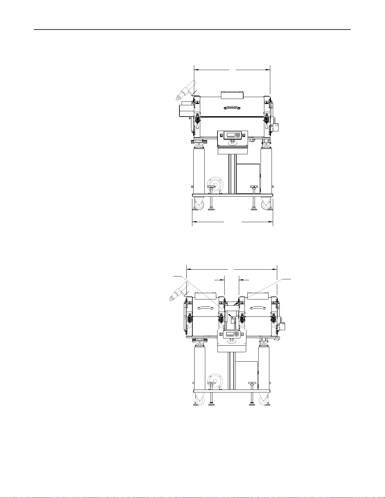
DIMENSIONS
A
32.63
INTERMEDIATE PRODUCT
SUPPORT ROLLER
A
6.14
OPTIONAL EXHAUST HOOD
Research, Inc. 6
Page 10
Model 4069 ProfileIRTM User Manual Specifications
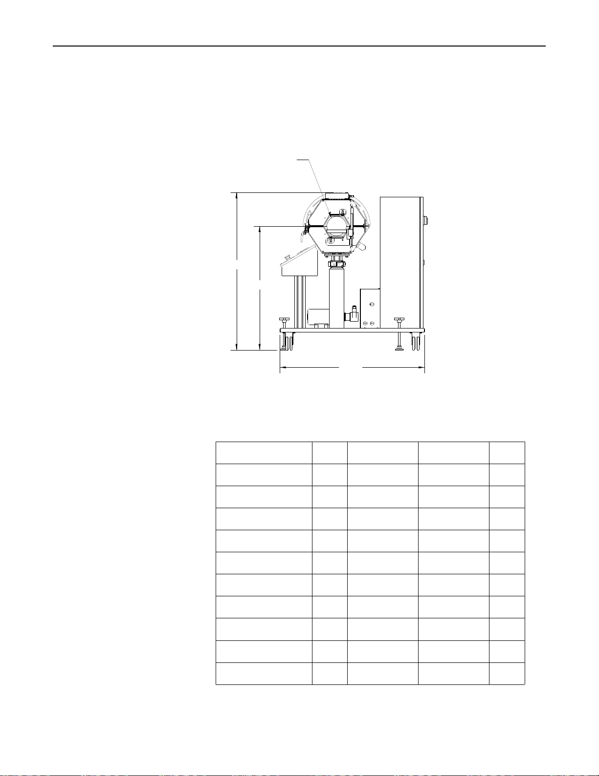
DIMENSIONS
D DIA
C
B
MODEL NUMBER A B
4069P-12R-10L
4069P-12R-16L
4069P-12R-25L
4069P-12R-38L
4069P-18R-10L
4069P-18R-16L
4069P-18R-25L
4069P-18R-38L
4069P-12R-10L-DUAL
4069P-18R-10L-DUAL
16.13
(410)
21.75
(552)
30.75
(781)
43.75
(1111)
16.13
(410)
21.75
(552)
30.75
(781)
43.75
(1111)
38.39
(975)
38.39
(975)
44.00
MIN MAX
36.75 44.75
(933) (1137)
36.75 44.75
(933) (1137)
36.75 44.75
(933) (1137)
36.75 44.75
(933) (1137)
38.00 46.00
(965) (1168)
38.00 46.00
(965) (1168)
38.00 46.00
(965) (1168)
38.00 46.00
(965) (1168)
36.75 44.75
(933) (1137)
38.00 46.00
(965) (1168)
C
MIN MAX
44.97 52.97
(1142) (1345)
44.97 52.97
(1142) (1345)
44.97 52.97
(1142) (1345)
44.97 52.97
(1142) (1345)
47.89 55.89
(1216) (1419)
47.89 55.89
(1216) (1419)
47.89 55.89
(1216) (1419)
47.89 55.89
(1216) (1419)
44.97 52.97
(1142) (1345)
47.89 55.89
(1216) (1419)
D DIA
3.22
(82)
3.22
(82)
3.22
(82)
3.22
(82)
5.90
(150)
5.90
(150)
5.90
(150)
5.90
(150)
3.22
(82)
5.90
(150)
IN
(MM)
Research, Inc. 7
Page 11
Model 4069 ProfileIRTM User Manual Installation
WIRING
Installation
This section describes how to wire the Model 4069P power control system. The
features and options mentioned here are identified in the model number found inside
the enclosure.
WARNING!
Hazardous voltages are present at the main disconnect switch and load terminals.
Always remove AC line voltage from the system before making contact with internal
assemblies, line or load wiring, or fuses. Also remove AC line voltage from the
system
before making connections, equipment changes, or resistance measurements.
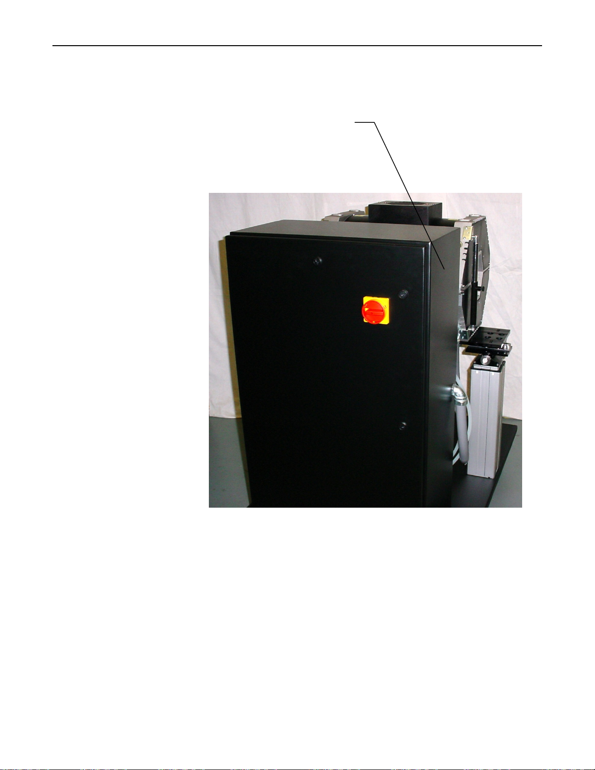
Conduit entry into the system should be made near the right side of the cabinet for
power wiring. Assure that metal fragments are not allowed to fall into the equipment
while holes are made for conduit fittings. See Figure 1. Referring to the wiring
specification in the table, connect the external power lines to the top of the disconnect
switch.
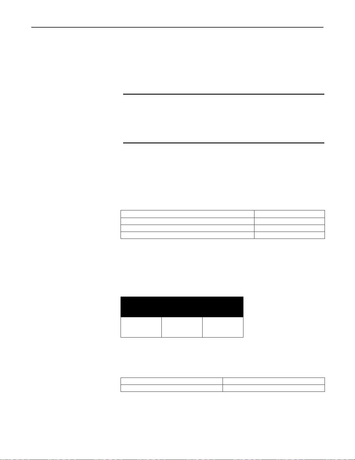
Wire Ratings:
Wire Temperature Rating:
Line/Load Wiring Voltage Rati ng (2 4 0 VAC systems) 300 VAC Minimum
Line/Load Wiring Voltage Rati ng (4 8 0 VAC systems) 600 VAC Minimum
75°C or Higher
Minimum Allowable Wire Sizes:
NOTE:
Ampacity ratings are based on NEC 310-16 using 75°C copper wire.
Current
Rating of
System
30 Amp
60 Amp
90 Amp
Line
Connections
10 AWG
6 AWG
3 AWG
Ground
Connection
10 AWG
8 AWG
8 AWG
Remote Inputs:
Remote Interlock Dry contact (open to stop)
Fast Stop Dry contact (open to stop)
Research, Inc. 8
Page 12
Model 4069 ProfileIRTM User Manual Installation
CONNECT POWER
THIS SIDE IF
POSSIBLE
Figure 1.
Research, Inc. 9
Page 13
Model 4069 ProfileIRTM User Manual Installation
CONTROL
CONNECTIONS
Remote Interlock
Switch
Remote Fast Stop
Water Connections
Air Connections
This feature provides for remote process interlock of the heater power. This is
accomplished by setting the heater power levels to 0 when switch is open and will
resume power levels when switch is closed. With the interlock open, the heater
cannot be turned on from the control system front panel. The switch contacts (dry)
must be open during the heater off condition. If this feature is desired, connect using
the following procedure:
1. Remove the factory-installed jumper at terminal block 1TB pins 20 and 21.
2. Connect the contacts of the switch to terminal block 1TB pins 20 and 21.
If more than one interlock switch is used in a system, wire the contacts in series and
then connect to the system.
This feature provides for remote process fast stop shutd o w n of the heater po wer,
water and fan cooling. This is accomplished by opening the heater power controller
contactor. With the fast stop switch open, the heater cannot be turned on from the
control system front panel. The switch contacts (dry) must be open during the heater
off condition. If this feature is desired, connect using the following procedure:
3. Remove the factory-installed jumper at terminal block 1TB pins 22 and 23.
4. Connect the contacts of the switch to terminal block 1TB pins 22 and 23.
If more than remote fast stop switch is used in a system, wire the contacts in series
and then connect to the system.
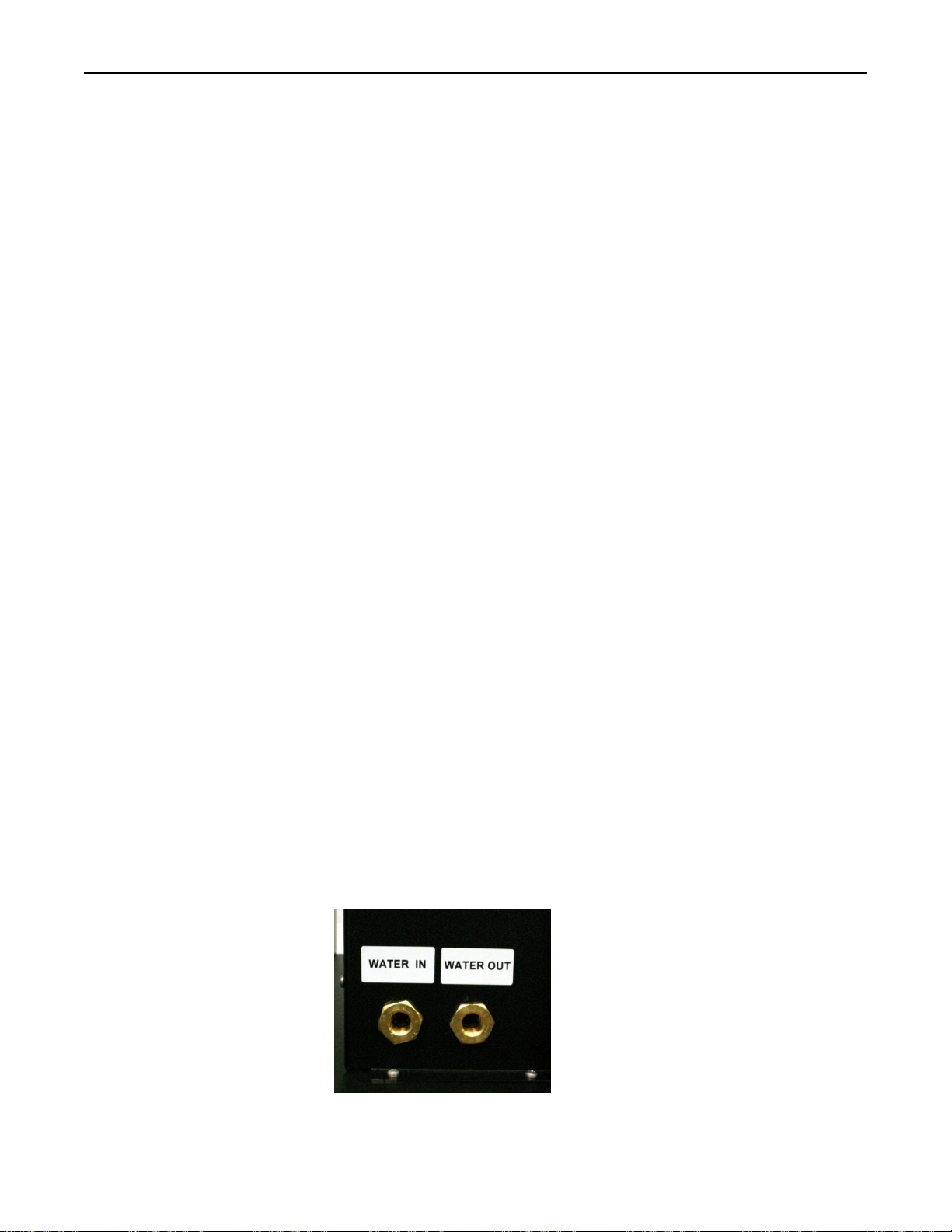
Use male 3/8” NPT fittings to connect the water input and output ports. See
Specifications for required flow rates.
Use a male 3/8” NPT fitting for the air input connection when the optional Air Curing
Nozzles and/or Pyrometer have been ordered.
Research, Inc. 10
Page 14
Model 4069 ProfileIRTM User Manual Operation
Figure 3
Operation
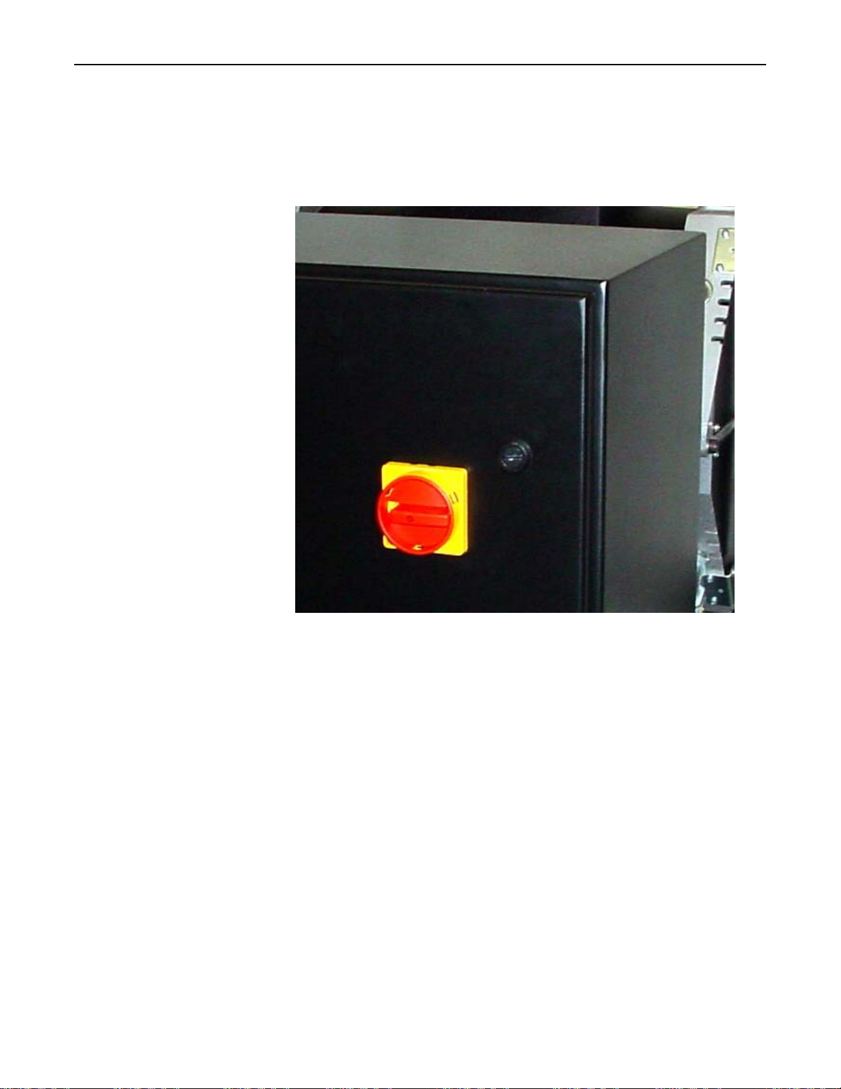
Main Disconnect Switch
The main disconnect switch turns on and off the power control system.
Note the following:
Before turning on the disconnect switch, check the following:
1. The load is wired an d ready for power to be applied to it.
2. All safety precautions are observed.
Research, Inc. 11
Page 15
Model 4069 ProfileIRTM User Manual Operation
OPERATOR
CONTROL
PANEL
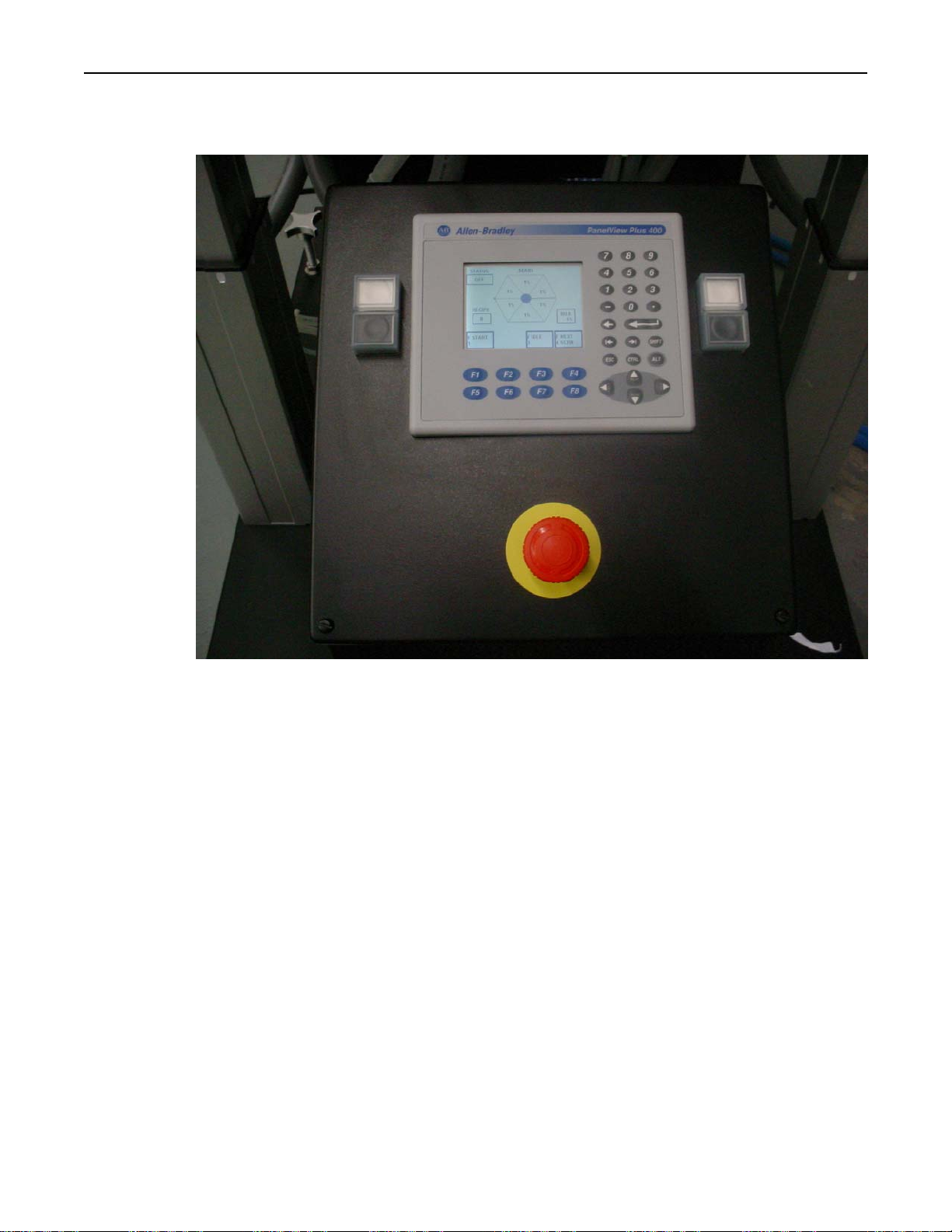
The operator control panel consists of the PanelView terminal, right
side and left side lift control switches, and a fast stop switch.
Lift Control Switches (2)
The white and black switches enable tilting of heater +/- 15° and have
up/down travel of 8 inches. The white switch raises the heater, the
black switch lowers the heater.
Fast Stop Switch (Red button, yellow background)
The Fast stop switch enables the immediate shutdown of the heater.
The heater contactor is turned off and the PLC is set to Stop. Push to
trip the switch, twist to reset or release the switch.
Research, Inc. 12
Page 16
Model 4069 ProfileIRTM User Manual Operation
PANELVIEW
TERMINAL
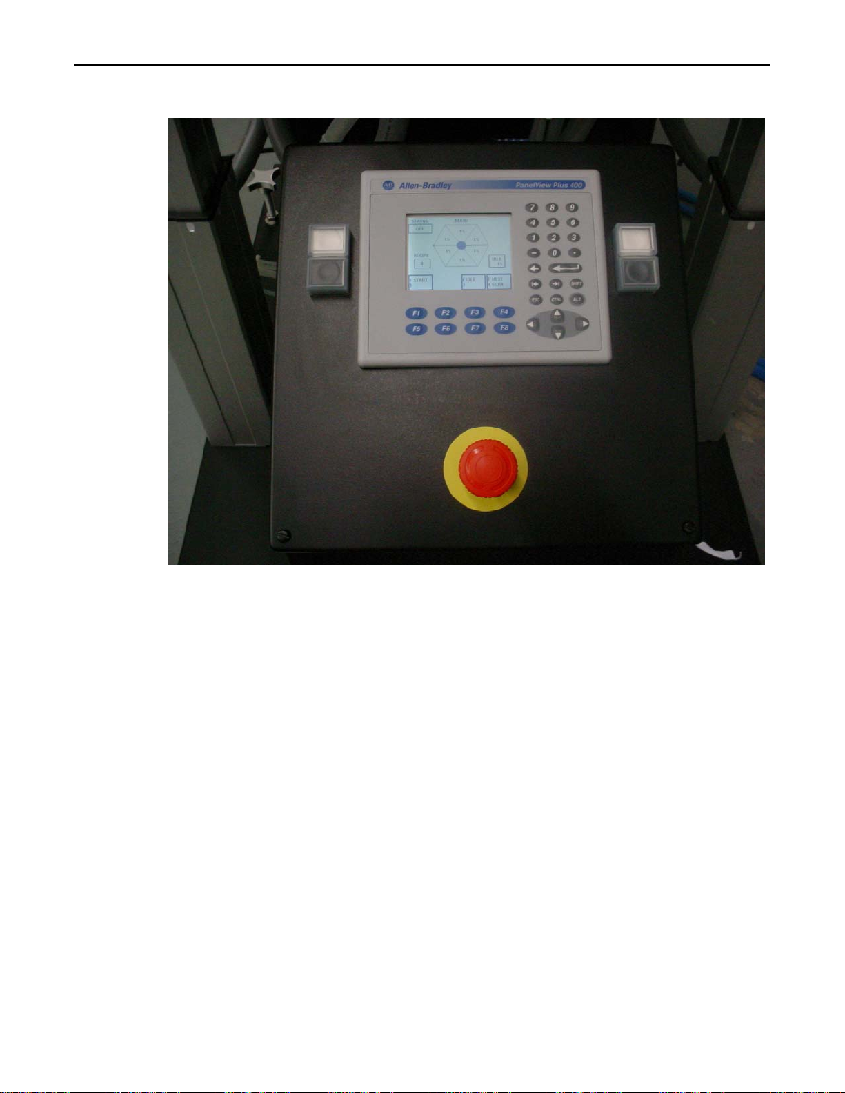
The PanelView terminal consists of a LCD display with keypad. 4
user screens are available: MAIN, RECIPE, ALARM, and OPTION.
The selection of the screens are made with the F4 (NEXT SCREEN)
key and the F5 (Previous Screen) key. The F5 key does not have a
legend displayed on the screen.
Note: The PanelView terminal is not a touchscreen, legends are
displayed to guide the operator. All entries are made from the keypad.
Research, Inc. 13
Page 17
Model 4069 ProfileIRTM User Manual Operation
MAIN SCREEN
NOTE: The START key
will not be displayed or
active if the recipe
displayed on the RECIPE
screen and the loaded
recipe, displayed on the
MAIN screen do not match.
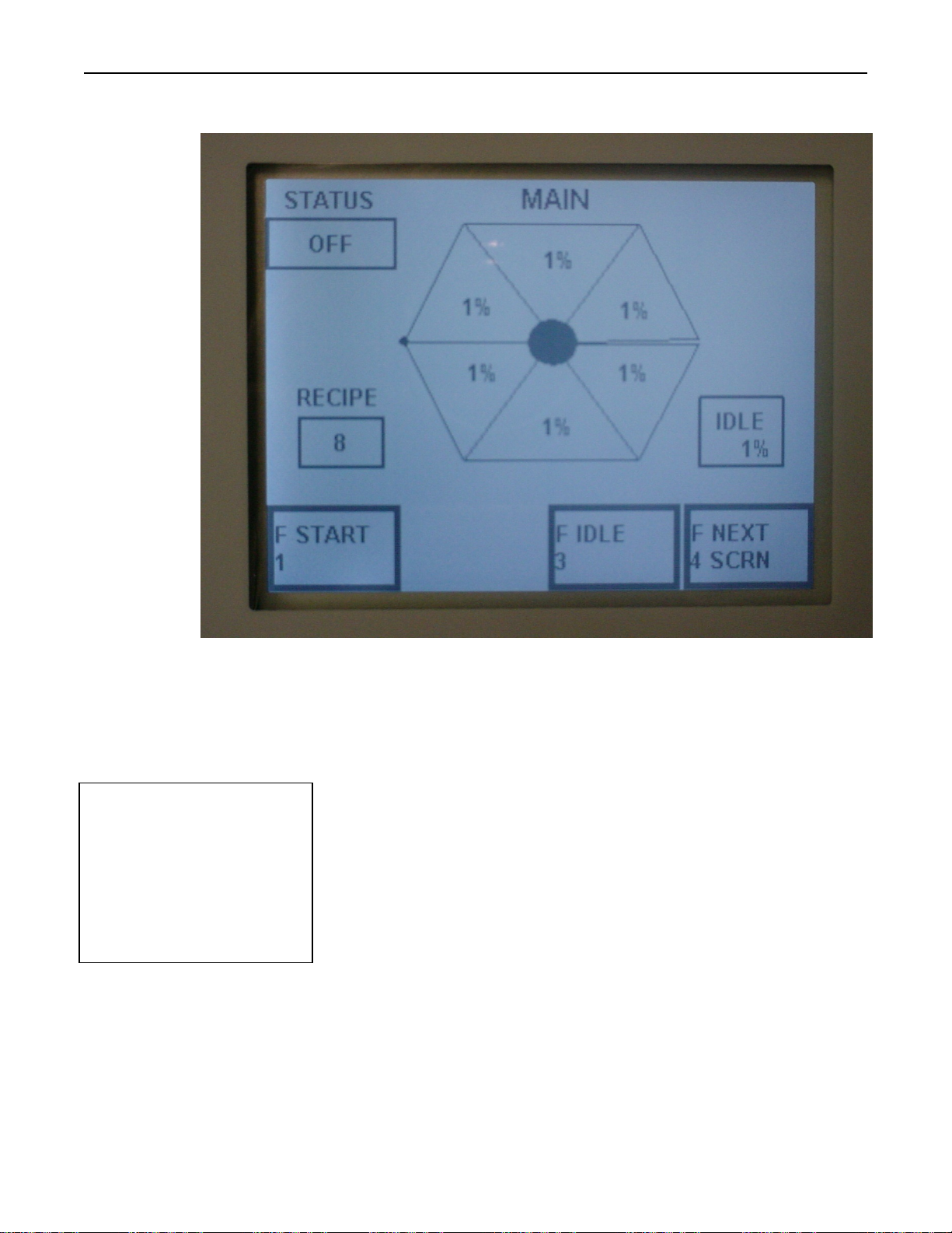
The MAIN screen allows monitoring of the system status, viewing the
current recipe, Starting/Stopping the recipe and changing between Idle
and Run. The display in the center represents a cross-sectional view of
the heater, with the hinge on the left side and the opening side on the
right. The darkened circle in the center represents the heating cavity
and it will blink when power is applied to the lamps.
Three keys are displayed and function when this screen is displayed, a
fourth key is active but not displayed.
F1 START key: This key will start and stop the system, once the
system is started the legend in the F1 box will change to STOP
allowing the F1 key to stop the system and the STATUS box will
display RUNNING. The system will not start if an alarm condition
exists and ALARM will be displayed in the STATUS box, see the
ALARM SCREEN page for more details.
Research, Inc. 14
Page 18

Model 4069 ProfileIRTM User Manual Operation
F3 IDLE key: This key will toggle the system between the zone
power levels and the idle power levels. Zone power levels are
displayed in the 6 pie shaped heater sections. The legend in the F3 box
displays IDLE when running or RESUME while in IDLE.
F4 NEXT SCRN key: This key will change the display to the next
screen in the following order: MAIN, RECIPE, ALARMS, and
OPTIONS. Each of these screens has the F4 key active.
F8 PREV SCRN key: This key is active on each of the screens but
has no legend displayed. This key will change the display to the
previous screen in the following order: MAIN, OPTIONS, ALARMS,
and RECIPE.
The system status will display one of the following: OFF, RUNNING,
IDLE, WAITING, and ALARM.
OFF displays when the heater is off and the system is shut down.
RUNNING is displayed when the system is operating at the zone
power settings of the selected recipe.
IDLE is displayed when the system is operating at the idle power
setting of the current recipe.
WAITING displays for one of two conditions: 1. The Remote
Interlock contacts are not closed or jumpered out. 2. The Motion
Detect Option has been enabled and product is not moving. In this
condition the system is ready to go with the zone power levels at 0 and
just “waiting” for the condition to change. Once the condition changes
the power levels go back to the recipe settings
ALARM is displayed when one of the alarm conditions exist. See the
Alarms Screen page for more details.
Research, Inc. 15
Page 19
Model 4069 ProfileIRTM User Manual Operation
RECIPE SCREEN
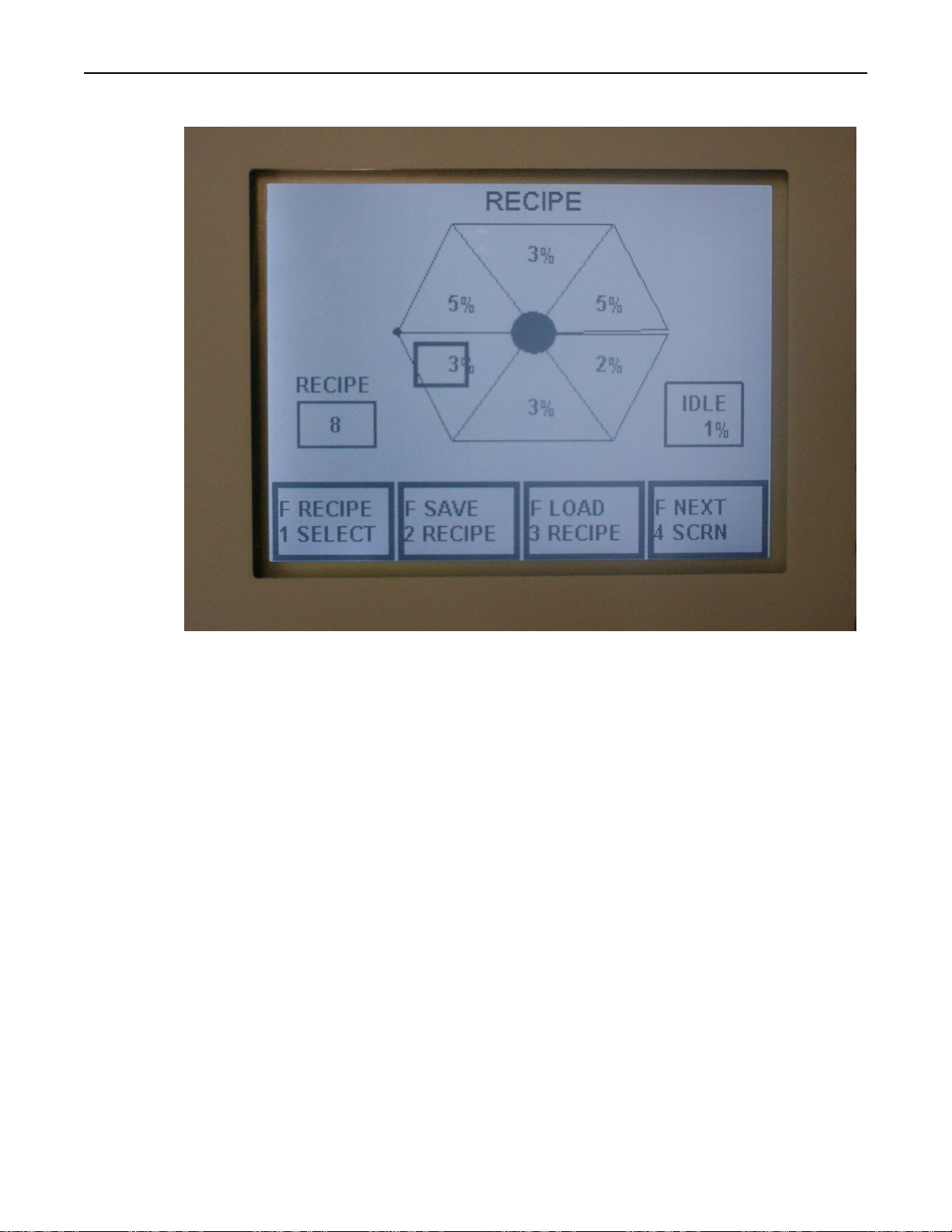
The RECIPE screen allows recipe selection, loading, creation or
modification, and saving of up to twenty recipes.
Recipe Selection The F1 key (RECIPE SELECT) will step through
the recipes from 1 to 20 and wrap back to 1. The zone power levels
and idle power level will be displayed as each recipe appears on the
screen. The F5 key is does not have a legend displayed, but it will
select the previous recipe.
Note: The RECIPE SELECT key is not displayed or available while in
the RUNNING mode. Only the current recipe may be modified at this
time.
Recipe Loading The F3 key (LOAD RECIPE) will take the selected
recipe and load it into active memory and change the display to the
MAIN screen, to allow the recipe to be run. Only after a recipe has
been loaded, can it be run.
Research, Inc. 16
Page 20
Model 4069 ProfileIRTM User Manual Operation
Recipe Creation/Modification After the recipe has been selected,
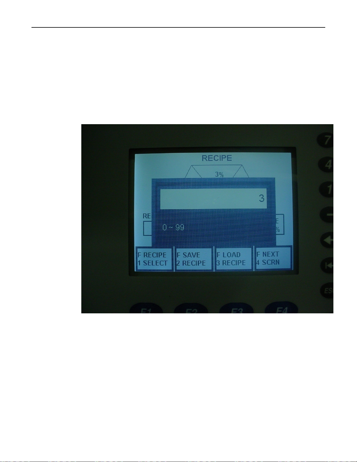
changes can be made to it. The Tab (→| ) and Back Tab ( |← ) keys
are used to move between the heating zones and idle power. The Enter
key ( ↵ ) is used to open the data entry window to allow power level
selection, 0 to 99%. The power level is entered on the numeric keypad
keys 0-9. The escape key (ESC) will abort an entry that has been
started. The backspace key (←) can be used for making changes. The
enter key will then load the power level into the temporary memory
storage until saved by the F2 key into nonvolatile memory.
Changes to the current recipe can be made while in the RUNNING
mode. Select the heating zone, change the power level and press F3
LOAD RECIPE. This will make a change to the current power levels
but only while it remains in RUNNING mode. By Saving the recipe
before Loading the change becomes part of the saved recipe in
nonvolatile memory.
Recipe Saving The F2 key (SAVE RECIPE) will save the current
recipe into nonvolatile memory. Recipes that are not saved will revert
back to zero or the last saved value after a power cycle or after
resuming from an idle state.
Research, Inc. 17
Page 21
Model 4069 ProfileIRTM User Manual Operation
ALARMS
SCREEN
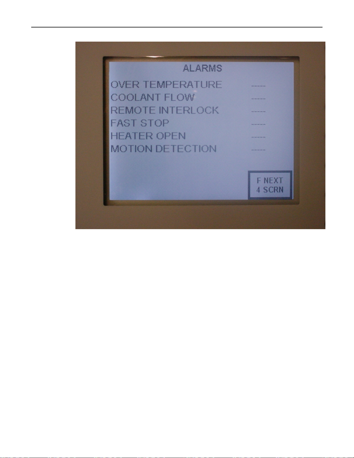
The ALARMS screen displays the status of each of the alarms. The
dashed line (-----) indicates no alarm. Alarms are of one of two types,
either a Critical or a Minor alarm. A Critical alarm will turn the
system to off, dropping out the heater contactor. It is due to an
abnormal condition that could damage equipment or harm personnel.
A Minor alarm puts the system in a waiting state where the power level
to the heaters is changed to 0%; once the condition has cleared the
power level returns to the pre-alarm level.
OVER TEMPERATURE The Over Temperature alarm is a Critical
alarm. A thermostat inside the 4069 Chamber heater monitors the
reflector temperature, when the preset value is exceeded the system
alarms and shuts down.
COOLANT FLOW The Coolant Flow alarm is a Critical alarm. A
flow switch on the system monitors the coolant flow through the 4069
Chamber heater. If it does not meet a minimum value or .25
gallon/minute (gpm) it will alarm and shut the system down. Note: A
flow rate of .25 gpm is significantly less than the heater requirement of
1.2 to 6.2 gpm depending on the heater. Inadequate coolant flow can
be a cause for the Over Temperature alarm.
Research, Inc. 18
Page 22

Model 4069 ProfileIRTM User Manual Operation
REMOTE INTERLOCK The Remote Interlock alarm is a Minor
alarm. This is a customer driven feature that can be used to signal a
line stoppage or any occurrence where the heaters should be
temporarily turned off. The opening of a dry contact is required to trip
this alarm, a jumper is installed from the factory to bypass this alarm
until it is hooked up. See the schematic for the location to make the
connection.
FAST STOP The Fast Stop Alarm is a Critical alarm. It is typically
used in an emergency, where the heat needs to be turned off in a hurry.
The Fast Stop can be initiated from the operator panel (the red
mushroom switch) or it can be wired into the production line. The
opening of a dry contact is required to trip this alarm, a jumper is
installed from the factory to bypass this alarm until it is hooked up.
See the schematic for the location to make the connection.
HEATER OPEN The Heater Open alarm is a Critical alarm. If
opened while running a very intense light would be directed at the
operator
MOTION DETECT The Motion Detect alarm is a Minor alarm. It
functions with the optional motion sensor, to set power output levels to
0 when the product is not moving. It can be enabled and disabled in
the OPTIONS menu.
Research, Inc. 19
Page 23
Model 4069 ProfileIRTM User Manual Operation
OPTIONS
SCREEN
The OPTIONS screen displays the status of each of the alarms. The
dashed line (-----) indicates no alarm. Alarms are of one of two types,
either a Critical or a Minor alarm. A Critical alarm will turn the
system to off , dropping out the heater contactor. It is due to an
abnormal condition that could damage equipment or harm personnel.
A Minor alarm puts the system in a waiting state where the power level
to the heaters is changed to 0%; once the condition has cleared the
power level returns to the pre-alarm level.
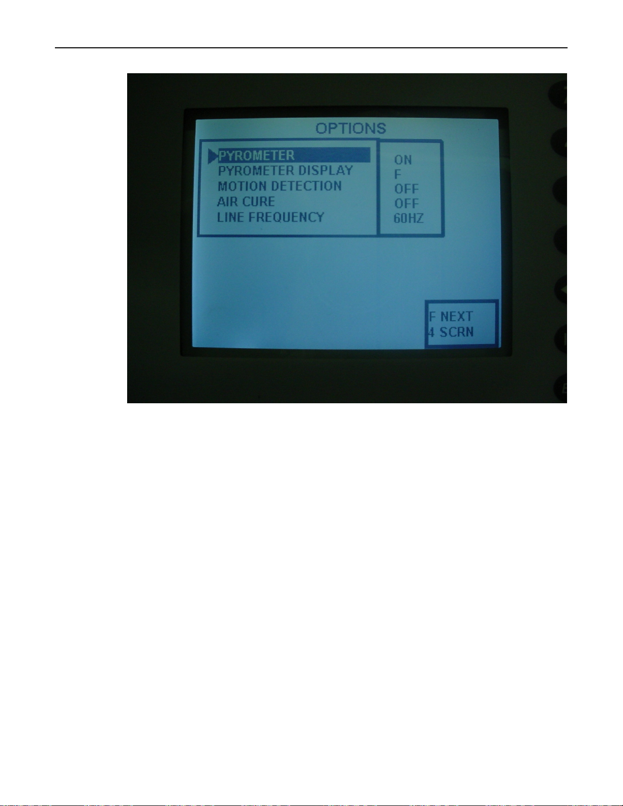
PYROMETER An option Pyrometer (optical temperature sensor) is
available for the 4069P. The pyrometer when installed and enabled
will display the temperature measured on the MAIN screen.
PYROMETER DISPLAY The temperature read by the Pyrometer
Option can be displayed in either degrees Fahrenheit or degrees Celsius
by making the appropriate selection here.
MOTION DETECTION An optional motion detection sensor is
available for the 4069P. The motion detection feature, when installed,
can be enabled and disabled by this selection. It consists of a Teflon
Research, Inc. 20
Page 24

Model 4069 ProfileIRTM User Manual Operation
covered roller and sensor,
when enabled it will change
the output power level to 0
when no motion is detected
for more than 2 seconds.
AIR CURE An optional air cure feature is available for the 4069P.
The air cure feature, when installed, can be enabled and disabled by
this selection. When enabled, a solenoid valve will be opened when
starting a recipe, allowing compressed air, directed by adjustable
nozzles, to be directed through the heating chamber.
LINE FREQUENCY The system is capable of running on AC power
at 60 Hz (USA) or at 50 Hz (Europe). This selection must be set
appropriately in order for the output power levels to work correctly.
Research, Inc. 21
Page 25

Model 4069 ProfileIRTM User Manual Maintenance
Maintenance and
ROUTINE
MAINTENANCE
LAMP REMOVAL,
REPLACEMENT,
INSTALLATION:
Trouble Shooting
The following bi-monthly routine maintenance is suggested:
1. Remove power connection to the system. Lock out power if possible. Carefully
vacuum any dust or dirt collecting within the enclosure. Use caution to not
disturb the wiring. Service more often in dust locations.
2. Clean the outside of the enclosure with glass cleaner and a soft cotton cloth as
necessary.
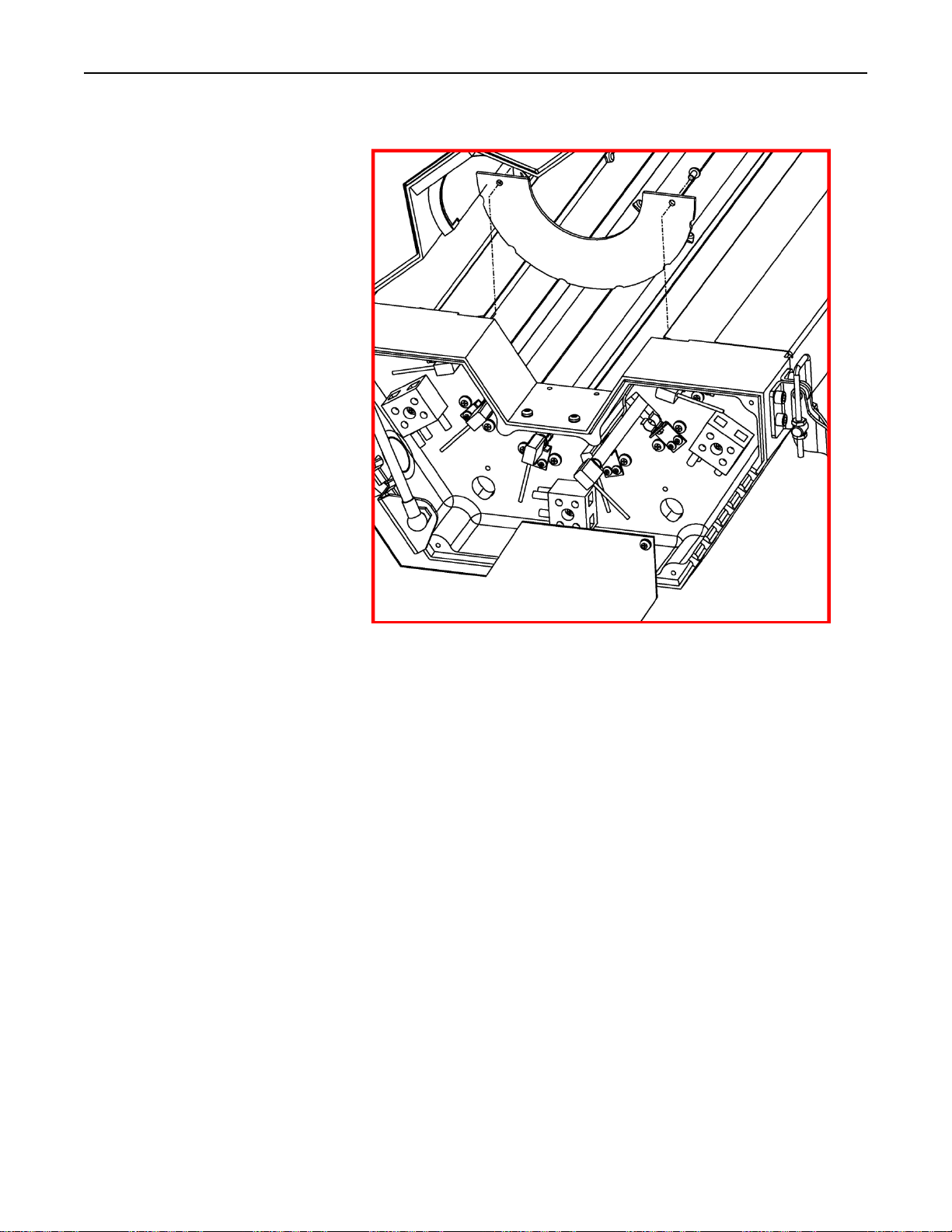
The T3-style lamps are installed into the Model 4069 when shipped from the factory.
The following procedure details the process to replace the lamps in the Model 4069
(reference Figure 6, 7, & 8):
Note:
Remove all power from the heater BEFORE attempting to install/replace the lamps.
Allow a minimum of ½-inch (12 mm) of slack in the lamp leads so that the leads are
not taut when inserted into the lamp terminal blocks.
Always take care to handle all lamps by the ceramic end seals and use clean cotton or
latex gloves to prevent contamination of the quartz lamp envelopes.
1. Re move quartz liner (see next section). Take this opportunity to clean the
liner.
2. Remove end-cover screws (4 per end cover).
3. Remove end covers on both ends of the heater.
4. Remove end-reflector screws (2 per reflector)
5. Remove end reflectors on both ends.
6. Carefully disengage lamp from clips (both ends).
7. Slide the end of the lamp through the rectangular cutout in the end casting
on one end of the heater through the rectangular cutout in the end casting of
the other end of the heater.
8. Position the lamp over the lamp clips so that the lighted portion of the lamp
is equally space in the reflector.
Note: Be sure that the Gas Fill Tip is facing away from the reflector
9. While holding the lamp on both ends by the ceramic end seals, with light
pressure push the lamp into the lamp clips. A slight twisting motion of the
lamp, while pushing the lamp into the clip, helps the lamp to seat properly.
Research, Inc. 22
Page 26
Model 4069 ProfileIRTM User Manual Maintenance
Figure 6.
10. Cut wire to a length allowing for a service loop.
11. Strip back the insulation on the end of the lamp leads approximately 1-1/2
inches (38 mm).
12. Insert the bare wire of each insulated lamp lead into the ceramic terminal
block position that previously held the old lamp. Push each lead wire into
the terminal block far enough so, that when tightened, the setscrew will hold
the lead securely.
13. Tighten the setscrews in each terminal block so the lead wires are held
securely (1.0 Ft.-Lbs. [1.4 N-m]).
14. Form a loop within each lead along its length. This loop will act as a strain
relief within the lead during normal operation of the heater.
15. Reinstall the end reflectors, end covers, and quartz liner.
Note:
Remove all power from the heater BEFORE attempting to install/replace the lamps.
Always use clean cotton or latex gloves when handling the split quartz liner so as not
to deposit any oils or grease from your hands onto the surface of the split quartz
liner.
Research, Inc.
23
Page 27
Model 4069 ProfileIRTM User Manual Maintenance
SPLIT QUARTZ
LINER CLEANING
AND REPLACEMENT
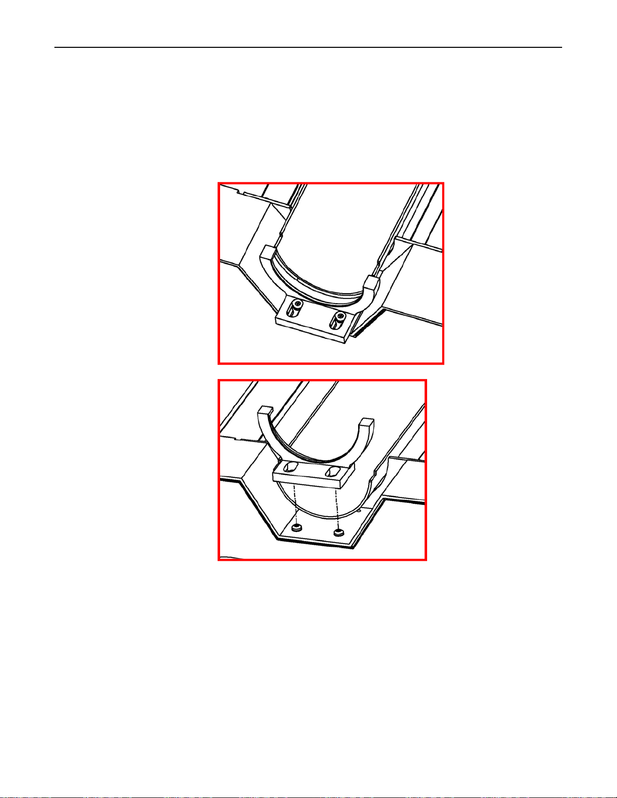
1. Open the Model 4069 Heater to allow access to each heater half for split
quartz liner installation.
2. Loosen the screws of one liner bracket and slide the bracket away from the
quartz-liner of one liner half at one end of the heater, while supporting the
liner with other hand.
Figure 7
Research, Inc.
Figure 8
3. Re move the bracket from the end casting of the heater.
4. G ently slide the quartz liner out of the grooves of the liner bracket from the
opposite end. Take care so that the quartz liner does chip or crack as it is
removed.
24
Page 28
Model 4069 ProfileIRTM User Manual Maintenance
CLEANING THE
REFLECTORS
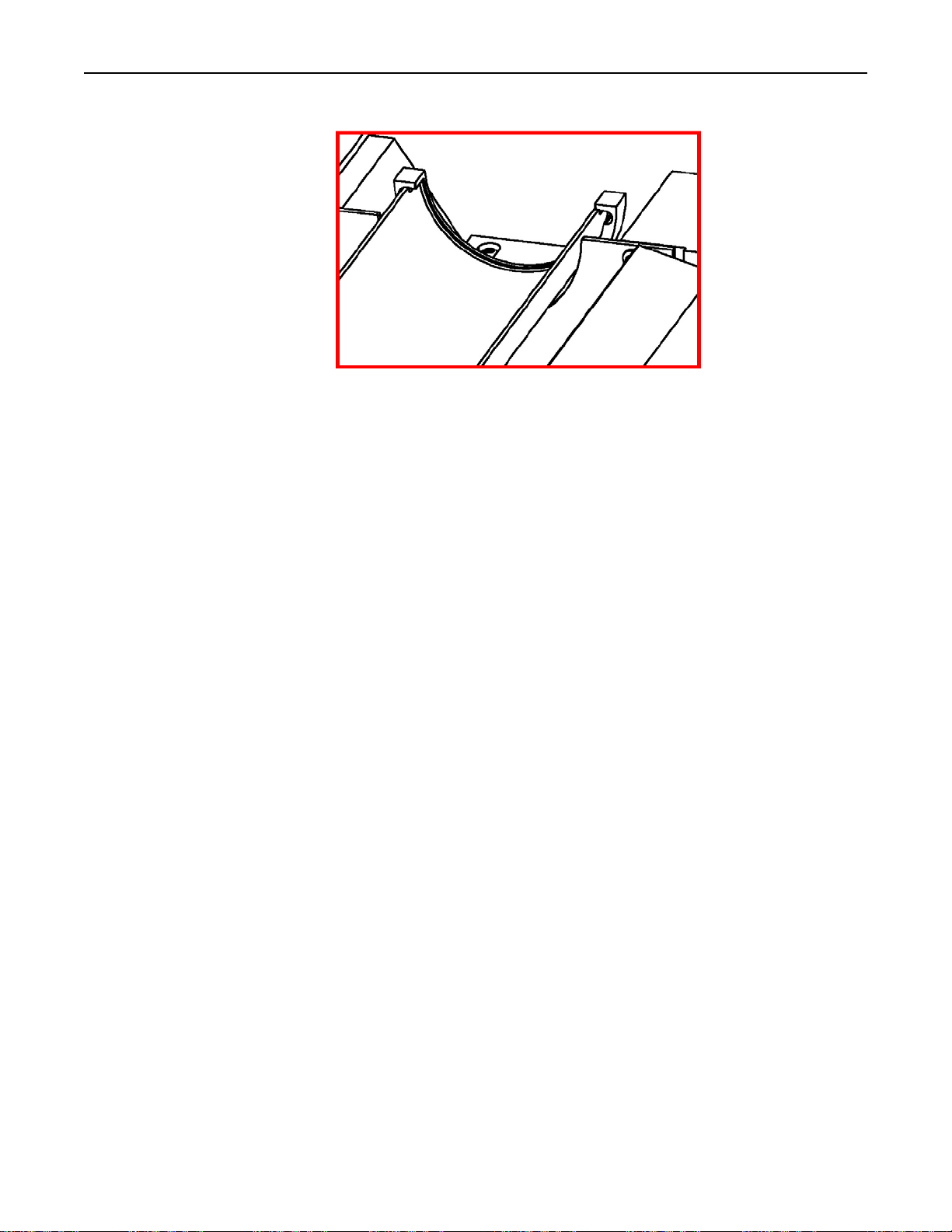
Figure 9
Clean reflectors provide the greatest radiant efficiency. If the reflector surface
becomes contaminated, it reflects less energy. The energy that is not reflected is lost,
absorbed by the reflectors, and removed by the cooling water and air.
The following procedure should be used to clean the Model 4069 reflectors:
If necessary, the reflectors may require re-polishing. This is permissible because the
reflector is solid aluminum and can be re-polished many times without damage from
continued erosion. A fine particle polishing compound, such as a chrome, semichrome, or soft metal polishing compound may be used. These types of compounds
can be found at a local automotive or metal-polishing supply house. Follow the
polishing instructions listed on the polishing product.
5. If cleaning the liner, use a non-abrasive glass cleaner (i.e. household
ammonia and water or isopropyl alcohol) and a clean, dry, lint-free cloth.
After cleaning, do not touch the outside surface of the liner unless wearing
cotton gloves.
6. Rein sert the edges of the liner into the grooves of the quartz-liner bracket.
7. Reinstall the other bracket and secure with the two bracket screws.
8. Rep eat this process for the other half of the liner.
1. Remove the lamps and quartz liner as described in Lamp
Removal/Replacement/Installation and Split Quartz Liner Cleaning and
Replacement.
2. Clean the reflectors with a mixture of warm water and common household
ammonia followed by a thorough wipe-down using a clean, water-dampened
flannel cloth.
3. D epending on the type of contamination present on the reflector, a suitable
solvent may be required to remove the contamination. The solvent must be
selected based on its inability to adversely affect the aluminum reflector.
4. Thoroughly wipe the reflector using the warm water/household ammonia
mixture followed by the dampened flannel cloth.
5.
Replace the lamps and quartz liner, as outlined in Lamp
Removal/Replacement/Installation and Section Split Quartz Lin e r Cleaning
and Replacement.
Research, Inc.
25
Page 29
Model 4069 ProfileIRTM User Manual Maintenance
REMOVING THE
REFLECTORS
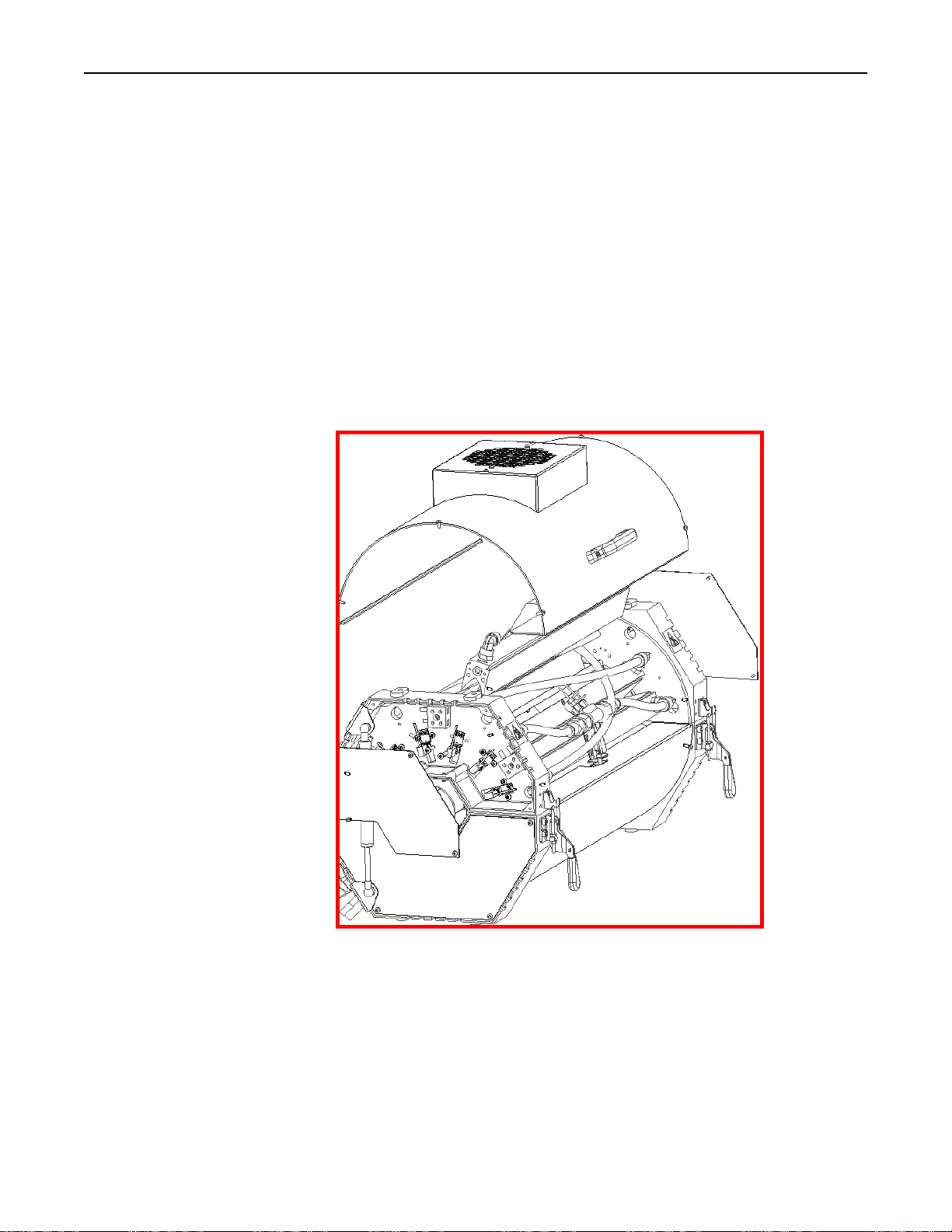
The reflectors can be removed from the Model 4069 Heater to make cleaning and
maintenance easier. The following procedure should be used to remove the Model
4069 reflectors:
Note:
Remove all power from the heater BEFORE attempting to install/replace the
heater reflectors.
1. Drain all cooling fluid from the heater and blow out the heater cooling lines
with compressed air.
2. Remove the heater-cover screws and heater cover.
Figure 10
Research, Inc. 26
Page 30
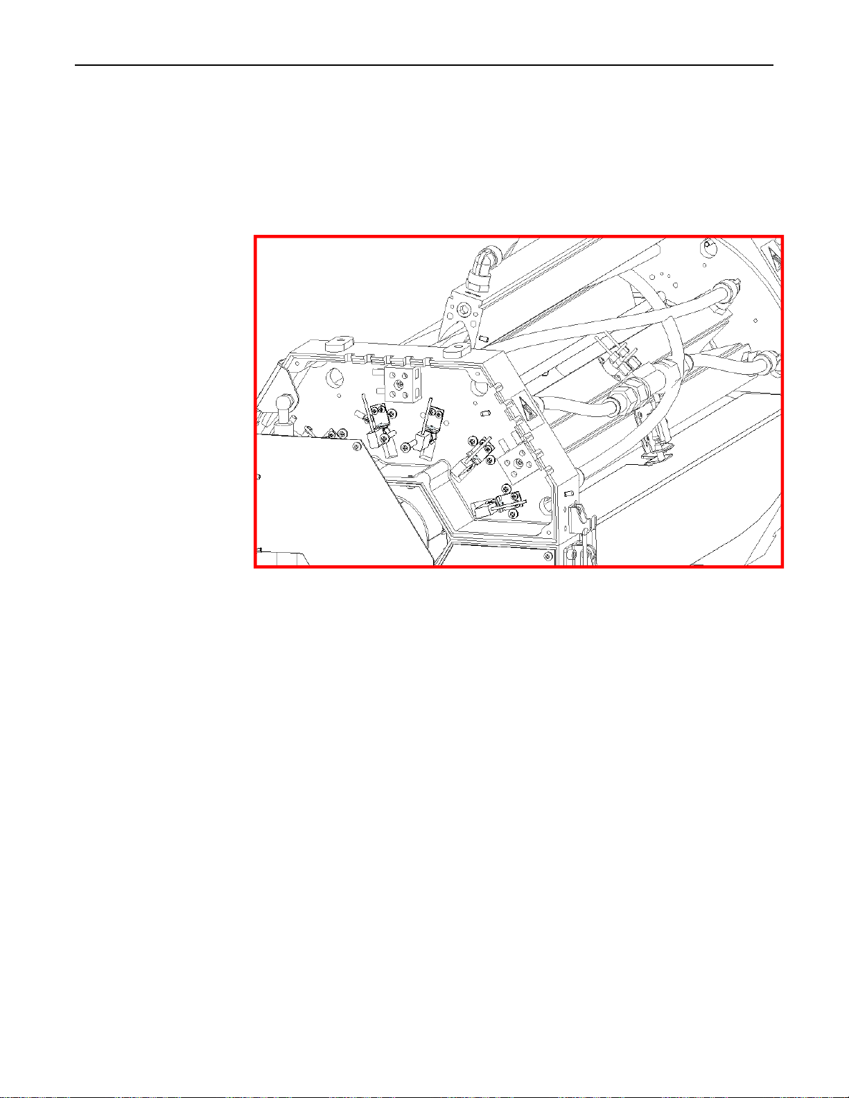
Model 4069 ProfileIRTM User Manual Maintenance
Figure 11
3. Disconnect the cooling line from the reflector to be maintained.
4. Loosen all screw from all reflectors on one side of the end casting of the
reflector to be maintained.
5. Remove the reflector mounting screws from the end casting of the reflector
to be maintained.
6. Remove the reflector.
Research, Inc. 27
Page 31

Model 4069 ProfileIRTM User Manual Maintenance
TROUBLESHOOTING
Symptom Action
System will not start. 1. Verify the F1 START legend is displayed on the
MAIN screen. If not, the recipe on the MAIN screen
and the recipe on the RECIPE screen do not match.
Load the desired recipe with the F3 LOAD key on
the RECIPE screen.
2. Check the STATUS box on the MAIN screen, if it is
ALARM, go to the ALARM screen, find and clear
the alarm.
3. Check the STATUS box on the MAIN screen , if it is
WAITING, go to the ALARM screen and find out if
it is Motion Detection or Remote Interlock causing
the condition. - Motion Detection will clear when
the product rotates the roller or can be disabled on
the OPTIONS screen. – Remote Interlock is
jumpered out from the factory 1TB20 and 22, or it
can be connected into the production line.
Power levels displayed on
the MAIN screen do not
match the RECIPE
screen.
Lamp zone not turning
on.
Operator Terminal has no
display.
Cannot change recipes. 1. Recipe change is only allowed when the STATUS
1. Verify the F3 IDLE key has not been pressed, legend
on screen will display RESUME if it has.
2. Selected recipe has not been loaded. Go to RECIPE
screen and LOAD the recipe.
3. Current recipe has been changed and not saved. Set
the recipe power levels to the desired level, then
SAVE and LOAD the recipe
1. Check load (zone) fuses. 10FU – 21FU
2. Check for burned out or broken lamps.
3. Check zone power level in recipe.
1. Verify disconnect switch is turned on and incoming
power is ok.
2. Check Line fuses. 1FU – 3FU
3. Check for green LED on the 24 VDC power supply,
then check power supply fuses if not lit. 4FU- 6FU
box displays OFF. While RUNNING the RECIPE
SELECT key is disabled, and the key legend is not
displayed. Stop the system and then change recipes.
Research, Inc. 28
Page 32
Model 4069 ProfileIRTM User Manual Maintenance
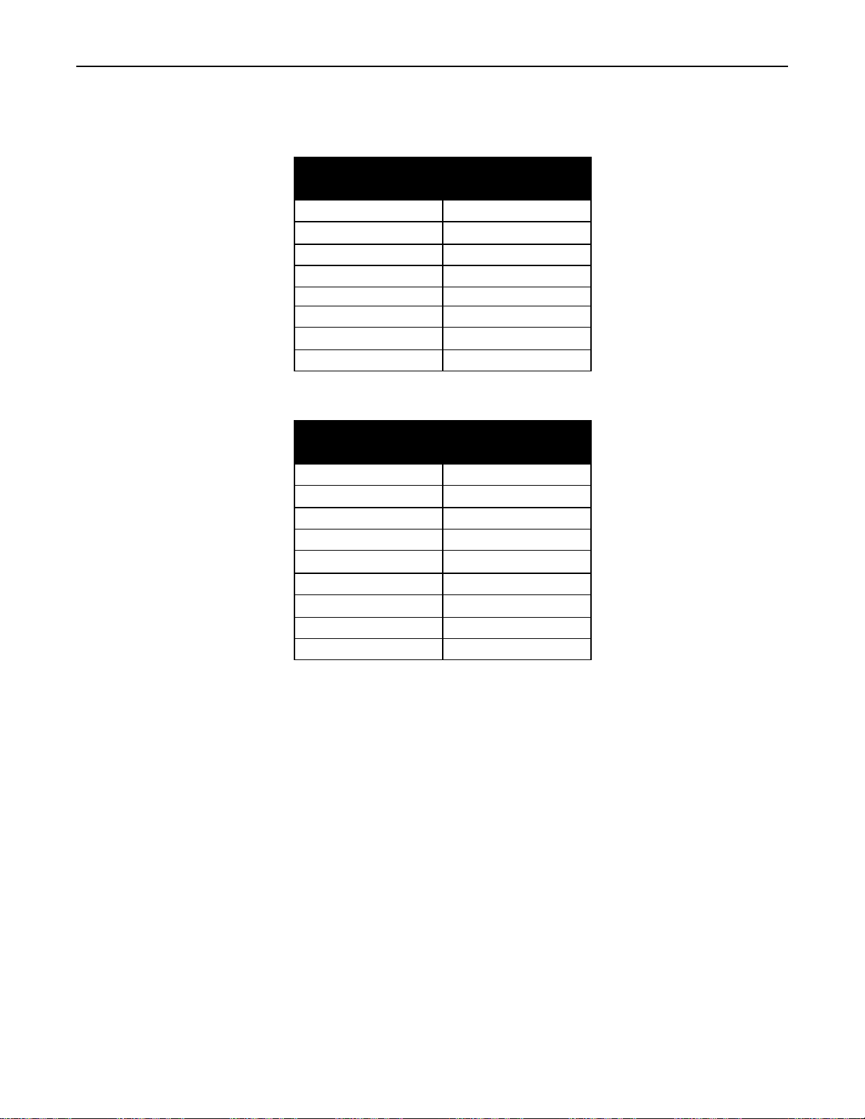
PLC DIGITAL I/O MAPPING
DIGITAL INPUTS
0 Flow Switch
1 Thermostat
2 Heater Closed
3 Fast Stop
4 Remote Interlock
5 Motion Sensor
DIGITAL OUTPUTS
0 Heater Enable
1 Cooling Solenoid / Fan
2 Heating Zone 1
3 Heating Zone 2
4 Heating Zone 3
5 Heating Zone 4
6 Heating Zone 5
7 Heating Zone 6
8 Air Cure Solenoid
The PLC should have 3 green LED’s on: Power, Run, and the COM 0 LED should
be flashing. (Communications to the Operator Terminal) The Amber LED’s on the
PLC indicate the state of the Digital Inputs and Outputs.
DESCRIPTION
DESCRIPTION
Research, Inc. 29
Page 33

Model 4069 ProfileIRTM User Manual Maintenance
Accessories, Spare, and Replacement Parts – Controls & Cart
Model Description
096191-006
107556-009
086445-016
099395-001
099396-001
107549-001
080821-001
055899-015
066798-004
107392-004
107392-001
107390-002
107390-001
107439-001
106783-011
106783-012
106783-013
106783-014
106784-011
106784-012
106784-013
106784-014
106783-013
106784-013
107358-011
107358-012
107358-014
107358-014
107396-011
107396-012
107396-013
107396-014
Control Cabinet:
Contactor- 3 phase, 100 amp, 24 VDC coil
Fuse-Cubefuse, 100 amp
Fuse-Time Delay, “CC”, 6 amp, 600 VAC
Switch-On /Off, 3 phase, 100 amp
Switch Actuator-Red/Yellow
Power Supply-480 VAC in, 24VDC out
Relay-DPDT, 10 amp, 24VDC, 650 ohm
Relay-SS, DC, 125 amp, 480 VAC
Varistor-Assembled, 480 VAC
Control Console:
Switch-Push Button, 2 head
Switch-Push Button, E-stop
Contact Block-Normally open
Contact Block-Normally closed
Actuator-Telescopic, 8” lift, 24 V
Cart
Replacement Gas Spring for 4069-12R-10L
Replacement Gas Spring for 4069-12R-16L
Replacement Gas Spring for 4069-12R-25L
Replacement Gas Spring for 4069-12R-38L
Replacement Gas Spring for 4069-18R-10L
Replacement Gas Spring for 4069-18R-16L
Replacement Gas Spring for 4069-18R-25L
Replacement Gas Spring for 4069-18R-38L
Replacement Gas Spring for 4069-12-DUAL
Replacement Gas Spring for 4069-18-DUAL
Gas Spring with Latch Replacement
Replacement Gas Spring & Latch for 4069-12R-10L
Replacement Gas Spring & Latch for 4069-12R-16L
Replacement Gas Spring & Latch for 4069-12R-25L
Replacement Gas Spring & Latch for 4069-12R-38L
Replacement Gas Spring & Latch for 4069-18R-10L
Replacement Gas Spring & Latch for 4069-18R-16L
Replacement Gas Spring & Latch for 4069-18R-25L
Replacement Gas Spring & Latch for 4069-18R-38L
Research, Inc. 30
Page 34

Model 4069 ProfileIRTM User Manual Maintenance
Accessories, Spare, and Replacement Parts – Heater
Model Description
103390-003
103390-004
103390-005
103390-007
103390-010
106721-001
106721-002
106721-003
106721-004
106778-001
106778-002
106895-001
106895-002
106895-003
106895-004
106895-005
106895-006
106895-007
106895-008
M4069P
Replacement Lamp For:
12kW or 18kW maximum-power rated heater (10 inch length, 1000-watts)
24kW or 36kW maximum-power rated heater (10 inch length, 2000-watts)
19kW or 29kW maximum-power rated heater (16 inch length, 1600-watts)
30kW or 45kW maximum-power rated heater (25 inch length, 2500-watts)
46kW or 68kW maximum-power rated heater (38 inch length, 3800-watts)
Replacement Reflector For:
10-inch length
16-inch length
25-inch length
38-inch length
Replacement End Reflectors (Four required per heater) for:
12-reflector size heater
18-reflector size heater
Spare Split Quartz Liner Half (Two required per heater) for:
12-reflector, 10-inch length
12-reflector, 16-inch length
12-reflector, 25-inch length
12-reflector, 38-inch length
18-reflector, 10-inch length
18-reflector, 16-inch length
18-reflector, 25-inch length
18-reflector, 38-inch length
Additional User Manual
Research, Inc. 31
 Loading...