

Prastel MR Series User Manual
Ricevitori serie MR
1. INFORMAZIONI GENERALI
Il ricevitore MR integra le funzioni di ricevitore e decodificatore di codice standard e di codice ‘rolling’.
Le sue memorie, sia di tipo tradizionale che rolling code, sono in grado di memorizzare fino a 1000 codici diversi generati da
trasmettitori delle famiglie MULTIPASS e MULTIPASS Roll. E’ possibile associare liberamente un qualsiasi pulsante del trasmettitore ad
uno qualunque dei relè monati a bordo.
Destinazione d’uso del prodotto: radio ricevitore in sistemi per apricancello.
2. CODIFICA ROLLING
Lo scopo di questa codifica è quello di impedire la possibilità di violazione del codice per cattura e ritrasmissione. La codifica rolling
comporta la trasmissione di una trama di bit costituita da una parte costante, diversa per ogni trasmettitore, dai bit di canale, relativi al
pulsante del trasmettitore attivato, più una parte che varia ad ogni trasmissione in modo pseudo-random (codice rolling) secondo un
algoritmo proprietario Prastel. La configurazione di questi bit varia tra due trasmissioni successive in modo non prevedibile. Il ricevitore
memorizza per autoapprendimento la parte di codice costante di ogni trasmettitore più il relativo codice rolling e aggiorna quest’ultimo
ad ogni trasmissione. Il trasmettitore viene riconosciuto solo se invia un codice rolling corrispondente alle 255 configurazioni successive
all’ultima trasmissione riconosciuta. Consente, tuttavia, il riallineamento e riconoscimento di un trasmettitore precedentemente
memorizzato che fosse uscito dall’intervallo consentito (ad esempio per un eccesso di trasmissioni non riconosciute o alla sostituzione
delle pile di alimentazione), premendo e rilasciando il pulsante di apprendimento del trasmettitore: viene in tal modo analizzata la
correttezza del codice, mantenendo i vantaggi della codifica variabile. Funzione RPA (comando di autoapprendimento a distanza del
trasmettitore).
3. CARATTERISTICHE TECNICHE
Alimentazione 12 - 24 VAC/DC
Consumo medio lavoro / riposo 90 mA / 20 mA
Numero di codici memorizzabili 1000
Numero di canali 4 per quadricanale; 2 per bicanale
Tipi di uscita monostabile, bistabile e temporizzata
Uscita Relè N.O.
Portata dei contatti 0,5 A @ 24 VAC/DC
Segnalazioni Led rossi: 4 per quadricanale, 2 per bicanale;
Temperatura di funzionamento -20/+55 °C
Temperatura di immagazzinamento -40/+85 °C
Dimensioni e peso
Tipo di Ricevitore Frequenza di ricezione
MR2/MR4 40.685 MHz
MR2E/MR4E 433.92 MHz
MR2F/MR4F 26.995 MHz
MR2K/MR4K 30.875 MHz
MR2N/MR4N 306 MHz
MR2S/MR4S 868.350 MHz
4. TENSIONE DI ALIMENTAZIONE
Il ricevitore MR può essere alimentato attraverso i terminali 1 e 3 (vedi figura) con 24 VAC/DC o 12 VAC/DC.
5. PROGRAMMAZIONE E CANCELLAZIONE DI CODICI
La memorizzazione di nuovi codici e la cancellazione totale dei codici in memoria viene eseguita attraverso il pulsante “ENTER RADIO”
del ricevitore.
Programmazione
• Alimentare il ricevitore
• Premere il pulsante “ENTER RADIO”. Tutti i led rossi si accendono per 2 secondi, quindi solo il primo led rimane acceso.
• Selezionare il relè che si vuole associare alla trasmissione premendo ripetutamente il pulsante “SET”.
• Effettuare una trasmissione premendo il pulsante desiderato. Ad ogni pulsante (canale) corrisponde una diversa trasmissione.
• Durante la memorizzazione il led lampeggia lentamente, a operazione conclusa il led ritorna acceso fisso.
• Se un led comincia a lampeggiare velocemente, il codice è gia stato memorizzato e associato al led che sta
lampeggiando. Ripetere la trasmissione per modificare l’assegnazione dal precedente relè a quello attualmente
selezionato.
• Se tutti i led rossi lampeggiano, la memoria è piena. Codice non memorizzato.
• Ripetere l’operazione per tutti i pulsanti (canali) che si vuole memorizzare, selezionando ogni volta il relè a cui li si vuole
associare.
• Ripetere l’operazione per tutti i trasmettitori che si vuole memorizzare.
• Per uscire dalla programmazione premere n uovamente il pulsante “ENTER RADIO”, i led si spengono. L’uscita è automatica
dopo 10 secondi dall’ultima operazione.
• I codici rimangono memorizzati anche se l’alimentazione viene a mancare.
Cancellazione totale dei codici
• Alimentare il ricevitore
• Tenere premuto il pulsante “ENTER RADIO” fino a che i led rossi cominciano a lampeggiare. Rilasciare e premere nuovamente
il pulsante per confermare la cancellazione. I led rimangono fissi durante l’operazione, ricominciano a lampeggiare più
velocemente ad operazione conclusa.
Led verde: 1 per ON/OFF
77 x 80 x 38 mm – 250 g.
ITALIANO
1
ISMREU_03_09.doc
Ricevitori serie MR
ITALIANO
6. SELEZIONE DELLA MODALITA’ DI COMMUTAZIONE DEI RELE’ DI USCITA
• Alimentare il ricevitore
• Premere il pulsante “SET”. Il led 1 comincia a lampeggiare secondo come è impostato il modo di commutazione del relè:
• Gruppi da tre lampeggi indicano che il relè è impostato in modo temporizzato
• Gruppi da due lampeggi indicano che il relè è impostato in modo bistabile
• Gruppi da un lampeggio indicano che il relè è impostato in modo monostabile
• Selezionare il relè che si vuole programmare premendo ripetutamente il pulsante “SET”.
• Per modificare la modalità di commutazione del relè selezionato:
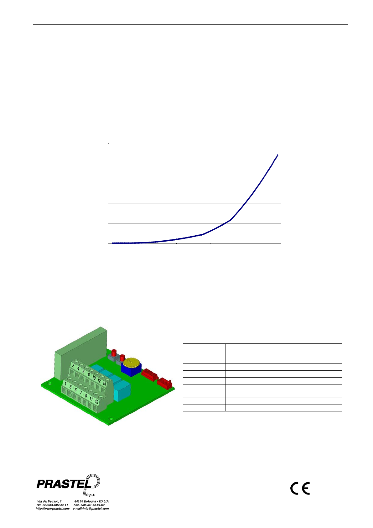
• Posizionare la rotella del trimmer come indicato dalla scritta sulla scheda: tutto a sinistra imposta il modo monostabile,
tutto a destra bistabile, posizioni intermedie impostano un modo temporizzato con tempo di commutazione come
mostrato in figura.
• Premere il pulsante “ENTER RADIO” per memorizzare la nuova impostazione.
• Per selezionare un altro relè premere “SET”.
• Per uscire dalla programmazione selezionare l’ultimo relè e poi premere nuovamente “SET”. I led si spegneranno. L’uscita è
automatica dopo 10 secondi dall’ultima operazione.
250
250
200
150
Secondi
Secondi
100
ISMREU_03_09.doc
50
0
0 50 100 150 200 250
Posizione del Trimmer (da sinistra a destra) e corrispondente tempo
di commutazione del relè di uscita
Valore letto dall'ADC
7. PROTEZIONE CON PASSWORD
E’ possibile proteggere la memoria a bordo con Password numerica tramite collegamento a PC e software WinGTProg. La Password è
un numero compreso tra 1 e 65535. Se la Password è compresa tra 1 e 32767 non è possibile inserire / cancellare utenti con il pulsante
“ENTER RADIO” ma è possibile modificare la programmazione dei relè con il pulsante “SET”. Se la Password è compresa tra 32768 e
65535 è disabilitata anche la modifica della programmazione dei relè con il pulsante “SET”.
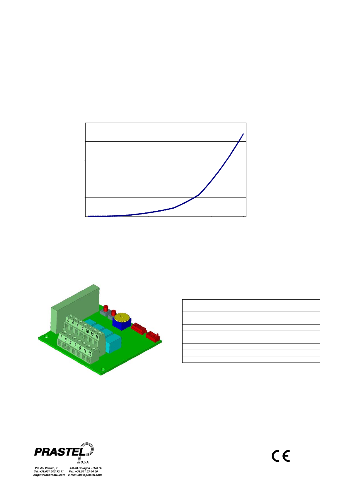
POSIZIONE DEI TERMINALI SULLA SCHEDA
Numerazione
morsettiera
Uscite
1 Alimentazione – 12/24V AC/DC
3 GND
2 Antenna
4 Schermo dell’antenna
5 - 7 Contatti Relè di uscita 1
6 - 8 Contatti Relè di uscita 2
9 - 11 Contatti Relè di uscita 3 (solo quadricanale)
10 - 12 Contatti Relè di uscita 4 (solo quadricanale)
2
MR series Receivers
1. GENERAL DESCRIPTION
The MR receiver integrates the functions of receiver and decoder of standard and ‘rolling’ codes. It’s memory, is capable of memorising
from up to 1000 different codes generated by transmitters of the MULTIPASS and MULTIPASS Roll families. It’s possible to link
whatever transmitter button to whatever relay mounted on the receiver.
Intended use of the equipment: radio receiver in garage-door systems.
2. ROLLING CODIFICATION
The purpose of this codification is to prevent the possibility of violation of the code by capture and retransmission. Rolling code
involves the transmission of a batch of bits consisting of a constant part, different for each transmitter, the channel bits related to the
transmitter switch activated plus a part that varies with each transmission in a pseudo-random manner (rolling code) in accordance with
a proprietary Prastel algorithm. Configuration of these bits varies unpredictably between two consecutive transmissions. The receiver,
by self-learning, memorises the constant part of the code of each transmitter plus the appropriate rolling code and updates the latter at
each transmission. The transmitter is recognised only if it sends a rolling code corresponding to the 255 configurations subsequent to
the last recognised transmission. Nevertheless it allows realignment and recognition of a previously memorised transmitter that has
overrun the permitted interval (e.g. due to an excess of unrecognised transmissions or on replacement of po wer supply batteries) by
pressing and releasing the transmitter learning button; in this way the correctness of the code is analysed, maintaining the advantages
of the variable codification. RPA Function (Transmitter remote self-learning command).
3. MAIN TECHNICAL FEATURES
Power supply 12 - 24 VAC/DC
Average Work/Rest consumption 90 mA / 20 mA
Number of codes memorisable 1000
Number of channels 4 for 4 channels; 2 for 2 channels
Types of output monostable, bistable and timed
Output Relay
Contact capacity 0,5 A @ 24 VAC/DC
Signals Red led: 4 on 4 channels, 2 on 2 channels
Working temperature -20/+55 °C
Storage temperature -40/+85 °C
Size / Weight
Type of receiver Reception frequency
MR2/MR4 40.685 MHz
MR2E/MR4E 433.92 MHz
MR2F/MR4F 26.995 MHz
MR2K/MR4K 30.875 MHz
MR2N/MR4N 306 MHz
MR2S/MR4S 868.350 MHz
4. SELECTION OF SUPPLY VOLTAGE
The MR receiver can be supplied through terminals 1 and 3 (see fig) with 24 VAC/DC or 12 VAC/DC.
5. CODE PROGRAMMING AND CANCELLATION
Operations of inserting a new code into the memory and cancelling the whole list of codes can be carried out using the same button
“ENTER RADIO” on the receiver.
Programming
• Power up the receiver correctly.
• Press button “ENTER RADIO”: all red leds lights up for 2 sec. Then only the first led remains on to indicate that
first relay is selected.
• Select the relay you wish to link to the transmitter pressing “SET” button repeatedly.
• Carry out a transmission pressing any transmitter button. Each button identifies a channel. Remember to repeat
the procedure for all transmitter buttons (channels) you want to program on the receiver, each time selcting the
desired associated relay.
• If led flashes slowly, insertion is running. When done the led returns in non-flashing state.
• If a led begins flashing quickly, the channel has already been programmed and is associated to the flashing
led. Carry out another transmission with the same button to update the programmation to selected relay.
• If all red leds flash at the same time, memory is full. Insertion is not done.
• The code is inserted into the memory. The led flashes during insertion. At the end the led returns to the non-flashing state,
indicating that a new code may be inserted.
• Memorise all the transmitters by carrying out a transmission with each one.
• At the end of the operation press button “ENTER RADIO” again to exit from the procedure. The led goes out. Exit from the
programme comes about automatically in any case 10 seconds after the last memorisation.
• The codes remain in the memory even if the receiver’s power supply is cut.
Total cancellation of codes
• Hold button “ENTER RADIO” pressed until all the red leds start flashing.
Press button “ENTER RADIO” again within 6 seconds to confirm cancellation. Leds are in non_flashing state during operation.
Confirmation is indicated by the led flashing with greater frequency.
Green Led: 1 for ON/OFF
77 x 80 x 38 mm – 250 g.
ENGLISH
3
ISMREU_03_09.doc
MR series Receivers
ENGLISH
6. SELECTION OF TYPE OF OUTPUT RELAY
• Power up the receiver correctly.
• Press button “SET”: the first led strat flashing according to programmed output mode.
• Group of only one flash means monostable output setted.
• Group of two flashes means bistable output setted.
• Group of three flashes means timed output setted.
• Select the relay you wish to set pressing “SET” button repeatedly.
• To change selected releay setting:
• Turn the trimmer wheel according to the arrow printed on the board: left end stroke select monostable
function, right end stroke bistable output. Midway positions select timed output as shown in figure below.
• Press “ENTER” button to save new setting into the selected relay.
• To set other relay press the “SET” button.
• To exit programming mode just select the last relay and then press the “SET” button another time. The led
goes out. Exit from the programme comes about automatically in any case 10 seconds after the last
memorisation.
250
250
200
150
Secondi
Seconds
100
ISMREU_03_09.doc
50
0
0 50 100 150 200 250
Trimmer Race (from left end to right end) and corresponding
switching time for timed relay output
Valore letto dall'ADC
7. PASSWORD PROTECTION
On board memory con be proteced with a numeric Password via PC link and WinGTProg software. Password must be a number in
the range from 1 to 65535. If Password is from 1 to 32767 only programmation / delation of user data through “ENTER RADIO” button
is disabled. If Password is from 32768 to 65535 either programmation / delation of user data and programmation of relays throu gh
“SET” button are disabled.
LAYOUT OF BUTTONS AND TERMINAL BOARDS
Terminal
Number
Terminal Function
1 Power Supply – 12/24V AC/DC
3 GND
2 Antenna core
4 Antenna GND
5 - 7 Output Relay 1
6 - 8 Output Relay 2
9 – 11 Output Relay 3 (only 4 channels version)
10 – 12 Output Relay 4 (only 4 channels version)
4
 Loading...