

Page 1

Powerware 9395 UPS and Plus 1 UPS
®
650–825 kVA
Installation and Operation Manual
Page 2

IMPORTANT SAFETY INSTRUCTIONS
SAVE THESE INSTRUCTIONS
This manual contains important instructions that you should follow during installation and maintenance of the UPS and batteries. Please
read all instructions before operating the equipment and save this manual for future reference.
CONSIGNES DE SÉCURITÉ IMPORTANTES
CONSERVER CES INSTRUCTIONS
Ce manuel comporte des instructions importantes que vous êtes invité à suivre lors de toute procédure d’installation et de maintenance
des batteries et de l’onduleur. Veuillez consulter entièrement ces instructions avant de faire fonctionner l’équipement et conserver ce
manuel afin de pouvoir vous y reporter ultérieurement.
W A R N I N G
This is a product for restricted sales distribution to informed partners (EN/IEC 62040−2). Installation restrictions or additional measures
may be needed to prevent electromagnetic disturbances.
Eaton, Powerware, X−Slot, LanSafe, PowerXpert, and Powerware HotSync are registered trademarks and ConnectUPS is a
trademark of Eaton Corporation or its subsidiaries and affiliates. IBM and AS/400 are registered trademarks of International
Business Machines Corporation. Modbus is a registered trademark of Schneider Electric. National Electrical Code and NEC are
registered trademarks of National Fire Protection Association, Inc. All other trademarks are property of their respective
companies.
ECopyright 2008 Eaton Corporation, Raleigh, NC, USA. All rights reserved. No part of this document may be reproduced in any
way without the express written approval of Eaton Corporation.
Page 3

Table of Contents
1 Introduction 1−1. . . . . . . . . . . . . . . . . . . . . . . . . . . . . . . . . . . . . . . . . . . . . . . . . . . . . . . . . . . . . . . . . . . . . . . . . . .
1.1 UPS Standard Features 1−1. . . . . . . . . . . . . . . . . . . . . . . . . . . . . . . . . . . . . . . . . . . . . . . . . . . . . . . . . . . . . . . . . . . . . . . . . . . . . . . . .
1.1.1 Installation Features 1−1. . . . . . . . . . . . . . . . . . . . . . . . . . . . . . . . . . . . . . . . . . . . . . . . . . . . . . . . . . . . . . . . . . . . . . . . . . . . . . .
1.1.2 Control Panel 1−2. . . . . . . . . . . . . . . . . . . . . . . . . . . . . . . . . . . . . . . . . . . . . . . . . . . . . . . . . . . . . . . . . . . . . . . . . . . . . . . . . . . .
1.1.3 Customer Interface 1−2. . . . . . . . . . . . . . . . . . . . . . . . . . . . . . . . . . . . . . . . . . . . . . . . . . . . . . . . . . . . . . . . . . . . . . . . . . . . . . . .
1.1.4 Advanced Battery Management 1−3. . . . . . . . . . . . . . . . . . . . . . . . . . . . . . . . . . . . . . . . . . . . . . . . . . . . . . . . . . . . . . . . . . . . . . .
1.1.5 Power Management Software 1−3. . . . . . . . . . . . . . . . . . . . . . . . . . . . . . . . . . . . . . . . . . . . . . . . . . . . . . . . . . . . . . . . . . . . . . . .
1.2 Options and Accessories 1−4. . . . . . . . . . . . . . . . . . . . . . . . . . . . . . . . . . . . . . . . . . . . . . . . . . . . . . . . . . . . . . . . . . . . . . . . . . . . . . . .
1.2.1 Field Installed UPM 1−4. . . . . . . . . . . . . . . . . . . . . . . . . . . . . . . . . . . . . . . . . . . . . . . . . . . . . . . . . . . . . . . . . . . . . . . . . . . . . . .
1.2.2 Inherent Redundancy 1−4. . . . . . . . . . . . . . . . . . . . . . . . . . . . . . . . . . . . . . . . . . . . . . . . . . . . . . . . . . . . . . . . . . . . . . . . . . . . . .
1.2.3 Sync Control 1−4. . . . . . . . . . . . . . . . . . . . . . . . . . . . . . . . . . . . . . . . . . . . . . . . . . . . . . . . . . . . . . . . . . . . . . . . . . . . . . . . . . . .
1.2.4 Monitoring and Communication 1−4. . . . . . . . . . . . . . . . . . . . . . . . . . . . . . . . . . . . . . . . . . . . . . . . . . . . . . . . . . . . . . . . . . . . . . .
1.2.5 Single−Feed Kit 1−5. . . . . . . . . . . . . . . . . . . . . . . . . . . . . . . . . . . . . . . . . . . . . . . . . . . . . . . . . . . . . . . . . . . . . . . . . . . . . . . . . .
1.2.6 Separate Rectifier Input 1−5. . . . . . . . . . . . . . . . . . . . . . . . . . . . . . . . . . . . . . . . . . . . . . . . . . . . . . . . . . . . . . . . . . . . . . . . . . . .
1.2.7 Distributed Bypass System 1−5. . . . . . . . . . . . . . . . . . . . . . . . . . . . . . . . . . . . . . . . . . . . . . . . . . . . . . . . . . . . . . . . . . . . . . . . . .
1.2.8 Input Output Module Configuration 1−5. . . . . . . . . . . . . . . . . . . . . . . . . . . . . . . . . . . . . . . . . . . . . . . . . . . . . . . . . . . . . . . . . . . .
1.3 Battery System 1−5. . . . . . . . . . . . . . . . . . . . . . . . . . . . . . . . . . . . . . . . . . . . . . . . . . . . . . . . . . . . . . . . . . . . . . . . . . . . . . . . . . . . . . .
1.4 Basic System Configurations 1−6. . . . . . . . . . . . . . . . . . . . . . . . . . . . . . . . . . . . . . . . . . . . . . . . . . . . . . . . . . . . . . . . . . . . . . . . . . . . .
1.5 Using This Manual 1−6. . . . . . . . . . . . . . . . . . . . . . . . . . . . . . . . . . . . . . . . . . . . . . . . . . . . . . . . . . . . . . . . . . . . . . . . . . . . . . . . . . . .
1.6 Conventions Used in This Manual 1−6. . . . . . . . . . . . . . . . . . . . . . . . . . . . . . . . . . . . . . . . . . . . . . . . . . . . . . . . . . . . . . . . . . . . . . . . . .
1.7 Symbols, Controls, and Indicators 1−7. . . . . . . . . . . . . . . . . . . . . . . . . . . . . . . . . . . . . . . . . . . . . . . . . . . . . . . . . . . . . . . . . . . . . . . . . .
1.8 For More Information 1−7. . . . . . . . . . . . . . . . . . . . . . . . . . . . . . . . . . . . . . . . . . . . . . . . . . . . . . . . . . . . . . . . . . . . . . . . . . . . . . . . . . .
1.9 Getting Help 1−8. . . . . . . . . . . . . . . . . . . . . . . . . . . . . . . . . . . . . . . . . . . . . . . . . . . . . . . . . . . . . . . . . . . . . . . . . . . . . . . . . . . . . . . . .
2 Safety Warnings 2−1. . . . . . . . . . . . . . . . . . . . . . . . . . . . . . . . . . . . . . . . . . . . . . . . . . . . . . . . . . . . . . . . . . . . . . .
Section I – Installation
3 UPS Installation Plan and Unpacking 3−1. . . . . . . . . . . . . . . . . . . . . . . . . . . . . . . . . . . . . . . . . . . . . . . . . . . . . . .
3.1 Creating an Installation Plan 3−1. . . . . . . . . . . . . . . . . . . . . . . . . . . . . . . . . . . . . . . . . . . . . . . . . . . . . . . . . . . . . . . . . . . . . . . . . . . . . .
3.2 Preparing the Site 3−1. . . . . . . . . . . . . . . . . . . . . . . . . . . . . . . . . . . . . . . . . . . . . . . . . . . . . . . . . . . . . . . . . . . . . . . . . . . . . . . . . . . . .
3.2.1 Environmental and Installation Considerations 3−1. . . . . . . . . . . . . . . . . . . . . . . . . . . . . . . . . . . . . . . . . . . . . . . . . . . . . . . . . . . . .
3.2.2 UPS System Power Wiring Preparation 3−8. . . . . . . . . . . . . . . . . . . . . . . . . . . . . . . . . . . . . . . . . . . . . . . . . . . . . . . . . . . . . . . . . .
3.2.3 UPS System Interface Wiring Preparation 3−19. . . . . . . . . . . . . . . . . . . . . . . . . . . . . . . . . . . . . . . . . . . . . . . . . . . . . . . . . . . . . . . .
3.2.4 Distributed Bypass Power Wiring Preparation 3−20. . . . . . . . . . . . . . . . . . . . . . . . . . . . . . . . . . . . . . . . . . . . . . . . . . . . . . . . . . . . .
3.3 Inspecting and Unpacking the UPS Cabinets 3−21. . . . . . . . . . . . . . . . . . . . . . . . . . . . . . . . . . . . . . . . . . . . . . . . . . . . . . . . . . . . . . . . . . .
4 UPS System Installation 4−1. . . . . . . . . . . . . . . . . . . . . . . . . . . . . . . . . . . . . . . . . . . . . . . . . . . . . . . . . . . . . . . . .
4.1 Preliminary Installation Information 4−1. . . . . . . . . . . . . . . . . . . . . . . . . . . . . . . . . . . . . . . . . . . . . . . . . . . . . . . . . . . . . . . . . . . . . . . . .
4.2 Unloading the UPS Sections from the Pallet 4−1. . . . . . . . . . . . . . . . . . . . . . . . . . . . . . . . . . . . . . . . . . . . . . . . . . . . . . . . . . . . . . . . . . .
4.3 Mechanically Joining the Sections 4−5. . . . . . . . . . . . . . . . . . . . . . . . . . . . . . . . . . . . . . . . . . . . . . . . . . . . . . . . . . . . . . . . . . . . . . . . .
4.4 Electrically Connecting the Sections 4−8. . . . . . . . . . . . . . . . . . . . . . . . . . . . . . . . . . . . . . . . . . . . . . . . . . . . . . . . . . . . . . . . . . . . . . . .
4.5 Field Installed UPM Installation 4−18. . . . . . . . . . . . . . . . . . . . . . . . . . . . . . . . . . . . . . . . . . . . . . . . . . . . . . . . . . . . . . . . . . . . . . . . . . .
4.6 Battery System Installation 4−18. . . . . . . . . . . . . . . . . . . . . . . . . . . . . . . . . . . . . . . . . . . . . . . . . . . . . . . . . . . . . . . . . . . . . . . . . . . . . . .
4.7 Distributed Bypass Tie Cabinet Installation 4−18. . . . . . . . . . . . . . . . . . . . . . . . . . . . . . . . . . . . . . . . . . . . . . . . . . . . . . . . . . . . . . . . . . .
EATON Powerware® 9395 UPS (650–825 kVA) Installation and Operation Manual S 164201725 Rev 2 www.powerware.com
i
Page 4

TABLE OF CONTENTS
4.8 Installing UPS External and Battery Power Wiring 4−18. . . . . . . . . . . . . . . . . . . . . . . . . . . . . . . . . . . . . . . . . . . . . . . . . . . . . . . . . . . . . . .
4.8.1 External Power Wiring Installation 4−18. . . . . . . . . . . . . . . . . . . . . . . . . . . . . . . . . . . . . . . . . . . . . . . . . . . . . . . . . . . . . . . . . . . . .
4.8.2 Battery Power Wiring 4−28. . . . . . . . . . . . . . . . . . . . . . . . . . . . . . . . . . . . . . . . . . . . . . . . . . . . . . . . . . . . . . . . . . . . . . . . . . . . . .
4.9 Installing Interface Connections 4−31. . . . . . . . . . . . . . . . . . . . . . . . . . . . . . . . . . . . . . . . . . . . . . . . . . . . . . . . . . . . . . . . . . . . . . . . . . .
4.9.1 TB1, TB2, and TB3 Connections (Other than TB1 Battery Interface Connections) 4−31. . . . . . . . . . . . . . . . . . . . . . . . . . . . . . . . . . . . .
4.9.2 TB1 Battery Interface Connections 4−36. . . . . . . . . . . . . . . . . . . . . . . . . . . . . . . . . . . . . . . . . . . . . . . . . . . . . . . . . . . . . . . . . . . . .
4.9.3 X−Slot Connections 4−38. . . . . . . . . . . . . . . . . . . . . . . . . . . . . . . . . . . . . . . . . . . . . . . . . . . . . . . . . . . . . . . . . . . . . . . . . . . . . . . .
4.10 Installing a REPO Switch 4−39. . . . . . . . . . . . . . . . . . . . . . . . . . . . . . . . . . . . . . . . . . . . . . . . . . . . . . . . . . . . . . . . . . . . . . . . . . . . . . . .
4.11 Installing Options, Accessories, and Distributed Bypass Control Wiring 4−42. . . . . . . . . . . . . . . . . . . . . . . . . . . . . . . . . . . . . . . . . . . . . . . .
4.12 Initial Startup 4−42. . . . . . . . . . . . . . . . . . . . . . . . . . . . . . . . . . . . . . . . . . . . . . . . . . . . . . . . . . . . . . . . . . . . . . . . . . . . . . . . . . . . . . . .
4.13 Completing the Installation Checklist 4−42. . . . . . . . . . . . . . . . . . . . . . . . . . . . . . . . . . . . . . . . . . . . . . . . . . . . . . . . . . . . . . . . . . . . . . . .
5 Installing Options and Accessories 5−1. . . . . . . . . . . . . . . . . . . . . . . . . . . . . . . . . . . . . . . . . . . . . . . . . . . . . . . .
5.1 Installing an Optional Powerware Hot Sync CAN Bridge Card 5−1. . . . . . . . . . . . . . . . . . . . . . . . . . . . . . . . . . . . . . . . . . . . . . . . . . . . . . .
5.2 Installing Distributed Bypass Control Wiring 5−4. . . . . . . . . . . . . . . . . . . . . . . . . . . . . . . . . . . . . . . . . . . . . . . . . . . . . . . . . . . . . . . . . . .
5.3 Installing an Optional Remote Monitor Panel II 5−9. . . . . . . . . . . . . . . . . . . . . . . . . . . . . . . . . . . . . . . . . . . . . . . . . . . . . . . . . . . . . . . . .
5.4 Installing an Optional Relay Interface Module II 5−11. . . . . . . . . . . . . . . . . . . . . . . . . . . . . . . . . . . . . . . . . . . . . . . . . . . . . . . . . . . . . . . .
5.5 Installing an Optional Supervisory Contact Module II 5−13. . . . . . . . . . . . . . . . . . . . . . . . . . . . . . . . . . . . . . . . . . . . . . . . . . . . . . . . . . . . .
5.6 Accessory Mounting Dimensions 5−15. . . . . . . . . . . . . . . . . . . . . . . . . . . . . . . . . . . . . . . . . . . . . . . . . . . . . . . . . . . . . . . . . . . . . . . . . . .
Section II – Operation
6 Understanding UPS Operation 6−1. . . . . . . . . . . . . . . . . . . . . . . . . . . . . . . . . . . . . . . . . . . . . . . . . . . . . . . . . . . . .
6.1 UPS System Overview 6−1. . . . . . . . . . . . . . . . . . . . . . . . . . . . . . . . . . . . . . . . . . . . . . . . . . . . . . . . . . . . . . . . . . . . . . . . . . . . . . . . . .
6.2 Single UPS 6−2. . . . . . . . . . . . . . . . . . . . . . . . . . . . . . . . . . . . . . . . . . . . . . . . . . . . . . . . . . . . . . . . . . . . . . . . . . . . . . . . . . . . . . . . . .
6.2.1 Modes 6−2. . . . . . . . . . . . . . . . . . . . . . . . . . . . . . . . . . . . . . . . . . . . . . . . . . . . . . . . . . . . . . . . . . . . . . . . . . . . . . . . . . . . . . . .
6.2.2 Normal Mode 6−2. . . . . . . . . . . . . . . . . . . . . . . . . . . . . . . . . . . . . . . . . . . . . . . . . . . . . . . . . . . . . . . . . . . . . . . . . . . . . . . . . . .
6.2.3 Bypass Mode 6−4. . . . . . . . . . . . . . . . . . . . . . . . . . . . . . . . . . . . . . . . . . . . . . . . . . . . . . . . . . . . . . . . . . . . . . . . . . . . . . . . . . . .
6.2.4 Battery Mode 6−5. . . . . . . . . . . . . . . . . . . . . . . . . . . . . . . . . . . . . . . . . . . . . . . . . . . . . . . . . . . . . . . . . . . . . . . . . . . . . . . . . . . .
6.3 Single UPS Unit System Oneline Configurations 6−7. . . . . . . . . . . . . . . . . . . . . . . . . . . . . . . . . . . . . . . . . . . . . . . . . . . . . . . . . . . . . . . .
6.4 Multiple UPS Distributed Bypass System 6−21. . . . . . . . . . . . . . . . . . . . . . . . . . . . . . . . . . . . . . . . . . . . . . . . . . . . . . . . . . . . . . . . . . . . .
6.4.1 Multiple UPS Parallel System Modes 6−21. . . . . . . . . . . . . . . . . . . . . . . . . . . . . . . . . . . . . . . . . . . . . . . . . . . . . . . . . . . . . . . . . . .
6.4.2 Normal Mode – Distributed Bypass 6−22. . . . . . . . . . . . . . . . . . . . . . . . . . . . . . . . . . . . . . . . . . . . . . . . . . . . . . . . . . . . . . . . . . . .
6.4.3 Bypass Mode – Distributed Bypass 6−23. . . . . . . . . . . . . . . . . . . . . . . . . . . . . . . . . . . . . . . . . . . . . . . . . . . . . . . . . . . . . . . . . . . .
6.4.4 Battery Mode – Distributed Bypass 6−24. . . . . . . . . . . . . . . . . . . . . . . . . . . . . . . . . . . . . . . . . . . . . . . . . . . . . . . . . . . . . . . . . . . .
6.5 Multiple UPS Distributed Bypass System Oneline Configurations 6−26. . . . . . . . . . . . . . . . . . . . . . . . . . . . . . . . . . . . . . . . . . . . . . . . . . . .
7 UPS Operating Instructions 7−1. . . . . . . . . . . . . . . . . . . . . . . . . . . . . . . . . . . . . . . . . . . . . . . . . . . . . . . . . . . . . . .
7.1 UPS Controls and Indicators 7−1. . . . . . . . . . . . . . . . . . . . . . . . . . . . . . . . . . . . . . . . . . . . . . . . . . . . . . . . . . . . . . . . . . . . . . . . . . . . . .
7.1.1 Control Panel 7−2. . . . . . . . . . . . . . . . . . . . . . . . . . . . . . . . . . . . . . . . . . . . . . . . . . . . . . . . . . . . . . . . . . . . . . . . . . . . . . . . . . . .
7.1.2 Circuit Breaker 7−2. . . . . . . . . . . . . . . . . . . . . . . . . . . . . . . . . . . . . . . . . . . . . . . . . . . . . . . . . . . . . . . . . . . . . . . . . . . . . . . . . . .
7.2 Using the Control Panel 7−2. . . . . . . . . . . . . . . . . . . . . . . . . . . . . . . . . . . . . . . . . . . . . . . . . . . . . . . . . . . . . . . . . . . . . . . . . . . . . . . . .
7.2.1 Status Indicators 7−3. . . . . . . . . . . . . . . . . . . . . . . . . . . . . . . . . . . . . . . . . . . . . . . . . . . . . . . . . . . . . . . . . . . . . . . . . . . . . . . . .
7.2.2 System Events 7−3. . . . . . . . . . . . . . . . . . . . . . . . . . . . . . . . . . . . . . . . . . . . . . . . . . . . . . . . . . . . . . . . . . . . . . . . . . . . . . . . . . .
7.2.3 Using the LCD and Pushbuttons 7−4. . . . . . . . . . . . . . . . . . . . . . . . . . . . . . . . . . . . . . . . . . . . . . . . . . . . . . . . . . . . . . . . . . . . . . .
7.2.4 Using the Menu 7−5. . . . . . . . . . . . . . . . . . . . . . . . . . . . . . . . . . . . . . . . . . . . . . . . . . . . . . . . . . . . . . . . . . . . . . . . . . . . . . . . . .
7.2.5 Mimic Screen 7−5. . . . . . . . . . . . . . . . . . . . . . . . . . . . . . . . . . . . . . . . . . . . . . . . . . . . . . . . . . . . . . . . . . . . . . . . . . . . . . . . . . .
7.2.6 Display Menu Operation 7−6. . . . . . . . . . . . . . . . . . . . . . . . . . . . . . . . . . . . . . . . . . . . . . . . . . . . . . . . . . . . . . . . . . . . . . . . . . . .
7.2.7 System Status Screen and Controls 7−8. . . . . . . . . . . . . . . . . . . . . . . . . . . . . . . . . . . . . . . . . . . . . . . . . . . . . . . . . . . . . . . . . . . .
7.2.8 Load Off Screen 7−10. . . . . . . . . . . . . . . . . . . . . . . . . . . . . . . . . . . . . . . . . . . . . . . . . . . . . . . . . . . . . . . . . . . . . . . . . . . . . . . . . .
ii
EATON Powerware® 9395 UPS (650–825 kVA) Installation and Operation Manual S 164201725 Rev 2 www.powerware.com
Page 5

TABLE OF CONTENTS
7.3 Single UPS Operation 7−11. . . . . . . . . . . . . . . . . . . . . . . . . . . . . . . . . . . . . . . . . . . . . . . . . . . . . . . . . . . . . . . . . . . . . . . . . . . . . . . . . .
7.3.1 Starting the UPS in Normal Mode 7−11. . . . . . . . . . . . . . . . . . . . . . . . . . . . . . . . . . . . . . . . . . . . . . . . . . . . . . . . . . . . . . . . . . . . .
7.3.2 Starting the UPS in Bypass Mode 7−12. . . . . . . . . . . . . . . . . . . . . . . . . . . . . . . . . . . . . . . . . . . . . . . . . . . . . . . . . . . . . . . . . . . . . .
7.3.3 Starting the UPMs 7−12. . . . . . . . . . . . . . . . . . . . . . . . . . . . . . . . . . . . . . . . . . . . . . . . . . . . . . . . . . . . . . . . . . . . . . . . . . . . . . . .
7.3.4 Transfer from Normal to Bypass Mode 7−14. . . . . . . . . . . . . . . . . . . . . . . . . . . . . . . . . . . . . . . . . . . . . . . . . . . . . . . . . . . . . . . . . .
7.3.5 Transfer from Bypass to Normal Mode 7−14. . . . . . . . . . . . . . . . . . . . . . . . . . . . . . . . . . . . . . . . . . . . . . . . . . . . . . . . . . . . . . . . . .
7.3.6 Transfer from Normal to Bypass Mode and Shut Down UPS 7−15. . . . . . . . . . . . . . . . . . . . . . . . . . . . . . . . . . . . . . . . . . . . . . . . . . .
7.3.7 Single UPM Shutdown 7−15. . . . . . . . . . . . . . . . . . . . . . . . . . . . . . . . . . . . . . . . . . . . . . . . . . . . . . . . . . . . . . . . . . . . . . . . . . . . .
7.3.8 UPS and Critical Load Shutdown 7−16. . . . . . . . . . . . . . . . . . . . . . . . . . . . . . . . . . . . . . . . . . . . . . . . . . . . . . . . . . . . . . . . . . . . . .
7.3.9 Charger Control 7−16. . . . . . . . . . . . . . . . . . . . . . . . . . . . . . . . . . . . . . . . . . . . . . . . . . . . . . . . . . . . . . . . . . . . . . . . . . . . . . . . . .
7.3.10 Using the UPS LOAD OFF Pushbutton or Command 7−17. . . . . . . . . . . . . . . . . . . . . . . . . . . . . . . . . . . . . . . . . . . . . . . . . . . . . . . . . .
7.3.11 Using the Remote Emergency Power−off Switch 7−18. . . . . . . . . . . . . . . . . . . . . . . . . . . . . . . . . . . . . . . . . . . . . . . . . . . . . . . . . . . .
7.4 Multiple UPS Distributed Bypass Operation 7−20. . . . . . . . . . . . . . . . . . . . . . . . . . . . . . . . . . . . . . . . . . . . . . . . . . . . . . . . . . . . . . . . . . .
7.4.1 Starting the Distributed Bypass System in Normal Mode 7−20. . . . . . . . . . . . . . . . . . . . . . . . . . . . . . . . . . . . . . . . . . . . . . . . . . . . .
7.4.2 Starting the Distributed Bypass System in Bypass Mode 7−21. . . . . . . . . . . . . . . . . . . . . . . . . . . . . . . . . . . . . . . . . . . . . . . . . . . . .
7.4.3 Starting the UPSs UPMs 7−21. . . . . . . . . . . . . . . . . . . . . . . . . . . . . . . . . . . . . . . . . . . . . . . . . . . . . . . . . . . . . . . . . . . . . . . . . . . .
7.4.4 Transfer from Normal to Bypass Mode 7−23. . . . . . . . . . . . . . . . . . . . . . . . . . . . . . . . . . . . . . . . . . . . . . . . . . . . . . . . . . . . . . . . . .
7.4.5 Transfer from Bypass to Normal Mode 7−23. . . . . . . . . . . . . . . . . . . . . . . . . . . . . . . . . . . . . . . . . . . . . . . . . . . . . . . . . . . . . . . . . .
7.4.6 Transfer from Normal to Bypass Mode and Shut Down all UPSs 7−24. . . . . . . . . . . . . . . . . . . . . . . . . . . . . . . . . . . . . . . . . . . . . . . .
7.4.7 Single UPM Shutdown 7−24. . . . . . . . . . . . . . . . . . . . . . . . . . . . . . . . . . . . . . . . . . . . . . . . . . . . . . . . . . . . . . . . . . . . . . . . . . . . .
7.4.8 UPS and Critical Load Shutdown 7−25. . . . . . . . . . . . . . . . . . . . . . . . . . . . . . . . . . . . . . . . . . . . . . . . . . . . . . . . . . . . . . . . . . . . . .
7.4.9 Charger Control 7−25. . . . . . . . . . . . . . . . . . . . . . . . . . . . . . . . . . . . . . . . . . . . . . . . . . . . . . . . . . . . . . . . . . . . . . . . . . . . . . . . . .
7.4.10 Using the UPS LOAD OFF Pushbutton or Command 7−26. . . . . . . . . . . . . . . . . . . . . . . . . . . . . . . . . . . . . . . . . . . . . . . . . . . . . . . . . .
7.4.11 Using the Remote Emergency Power−off Switch 7−27. . . . . . . . . . . . . . . . . . . . . . . . . . . . . . . . . . . . . . . . . . . . . . . . . . . . . . . . . . . .
8 Communication 8−1. . . . . . . . . . . . . . . . . . . . . . . . . . . . . . . . . . . . . . . . . . . . . . . . . . . . . . . . . . . . . . . . . . . . . . . .
8.1 X−Slot Cards 8−1. . . . . . . . . . . . . . . . . . . . . . . . . . . . . . . . . . . . . . . . . . . . . . . . . . . . . . . . . . . . . . . . . . . . . . . . . . . . . . . . . . . . . . . . .
8.2 eNotify Service 8−2. . . . . . . . . . . . . . . . . . . . . . . . . . . . . . . . . . . . . . . . . . . . . . . . . . . . . . . . . . . . . . . . . . . . . . . . . . . . . . . . . . . . . . .
8.2.1 eNotify Service Features 8−2. . . . . . . . . . . . . . . . . . . . . . . . . . . . . . . . . . . . . . . . . . . . . . . . . . . . . . . . . . . . . . . . . . . . . . . . . . . .
8.2.2 Installing eNotify Service 8−2. . . . . . . . . . . . . . . . . . . . . . . . . . . . . . . . . . . . . . . . . . . . . . . . . . . . . . . . . . . . . . . . . . . . . . . . . . .
8.3 Powerware LanSafe Power Management Software 8−3. . . . . . . . . . . . . . . . . . . . . . . . . . . . . . . . . . . . . . . . . . . . . . . . . . . . . . . . . . . . . .
8.4 Remote Notification 8−3. . . . . . . . . . . . . . . . . . . . . . . . . . . . . . . . . . . . . . . . . . . . . . . . . . . . . . . . . . . . . . . . . . . . . . . . . . . . . . . . . . .
8.5 Terminal Mode 8−4. . . . . . . . . . . . . . . . . . . . . . . . . . . . . . . . . . . . . . . . . . . . . . . . . . . . . . . . . . . . . . . . . . . . . . . . . . . . . . . . . . . . . . .
8.5.1 Display UPS Control Panel 8−4. . . . . . . . . . . . . . . . . . . . . . . . . . . . . . . . . . . . . . . . . . . . . . . . . . . . . . . . . . . . . . . . . . . . . . . . . . .
8.5.2 Event History Log 8−5. . . . . . . . . . . . . . . . . . . . . . . . . . . . . . . . . . . . . . . . . . . . . . . . . . . . . . . . . . . . . . . . . . . . . . . . . . . . . . . . .
8.6 Building Alarm Monitoring 8−7. . . . . . . . . . . . . . . . . . . . . . . . . . . . . . . . . . . . . . . . . . . . . . . . . . . . . . . . . . . . . . . . . . . . . . . . . . . . . . .
8.7 General Purpose Relay Contact 8−7. . . . . . . . . . . . . . . . . . . . . . . . . . . . . . . . . . . . . . . . . . . . . . . . . . . . . . . . . . . . . . . . . . . . . . . . . . . .
8.8 Remote Monitor Panel II 8−7. . . . . . . . . . . . . . . . . . . . . . . . . . . . . . . . . . . . . . . . . . . . . . . . . . . . . . . . . . . . . . . . . . . . . . . . . . . . . . . . .
8.9 Relay Interface Module II 8−9. . . . . . . . . . . . . . . . . . . . . . . . . . . . . . . . . . . . . . . . . . . . . . . . . . . . . . . . . . . . . . . . . . . . . . . . . . . . . . . .
8.10 Supervisory Contact Module II 8−10. . . . . . . . . . . . . . . . . . . . . . . . . . . . . . . . . . . . . . . . . . . . . . . . . . . . . . . . . . . . . . . . . . . . . . . . . . . .
9 UPS Maintenance 9−1. . . . . . . . . . . . . . . . . . . . . . . . . . . . . . . . . . . . . . . . . . . . . . . . . . . . . . . . . . . . . . . . . . . . . .
9.1 Important Safety Instructions 9−1. . . . . . . . . . . . . . . . . . . . . . . . . . . . . . . . . . . . . . . . . . . . . . . . . . . . . . . . . . . . . . . . . . . . . . . . . . . . .
9.2 Performing Preventive Maintenance 9−2. . . . . . . . . . . . . . . . . . . . . . . . . . . . . . . . . . . . . . . . . . . . . . . . . . . . . . . . . . . . . . . . . . . . . . . .
9.2.1 DAILY Maintenance 9−2. . . . . . . . . . . . . . . . . . . . . . . . . . . . . . . . . . . . . . . . . . . . . . . . . . . . . . . . . . . . . . . . . . . . . . . . . . . . . . .
9.2.2 MONTHLY Maintenance 9−2. . . . . . . . . . . . . . . . . . . . . . . . . . . . . . . . . . . . . . . . . . . . . . . . . . . . . . . . . . . . . . . . . . . . . . . . . . . .
9.2.3 PERIODIC Maintenance 9−5. . . . . . . . . . . . . . . . . . . . . . . . . . . . . . . . . . . . . . . . . . . . . . . . . . . . . . . . . . . . . . . . . . . . . . . . . . . . .
9.2.4 ANNUAL Maintenance 9−5. . . . . . . . . . . . . . . . . . . . . . . . . . . . . . . . . . . . . . . . . . . . . . . . . . . . . . . . . . . . . . . . . . . . . . . . . . . . .
9.2.5 BATTERY Maintenance 9−5. . . . . . . . . . . . . . . . . . . . . . . . . . . . . . . . . . . . . . . . . . . . . . . . . . . . . . . . . . . . . . . . . . . . . . . . . . . . .
9.3 Installing Batteries 9−5. . . . . . . . . . . . . . . . . . . . . . . . . . . . . . . . . . . . . . . . . . . . . . . . . . . . . . . . . . . . . . . . . . . . . . . . . . . . . . . . . . . .
9.4 Recycling the Used Battery or UPS 9−6. . . . . . . . . . . . . . . . . . . . . . . . . . . . . . . . . . . . . . . . . . . . . . . . . . . . . . . . . . . . . . . . . . . . . . . . .
9.5 Maintenance Training 9−6. . . . . . . . . . . . . . . . . . . . . . . . . . . . . . . . . . . . . . . . . . . . . . . . . . . . . . . . . . . . . . . . . . . . . . . . . . . . . . . . . .
EATON Powerware® 9395 UPS (650–825 kVA) Installation and Operation Manual S 164201725 Rev 2 www.powerware.com
iii
Page 6

TABLE OF CONTENTS
10 Product Specifications 10−1. . . . . . . . . . . . . . . . . . . . . . . . . . . . . . . . . . . . . . . . . . . . . . . . . . . . . . . . . . . . . . . . . .
10.1 Model Numbers 10−1. . . . . . . . . . . . . . . . . . . . . . . . . . . . . . . . . . . . . . . . . . . . . . . . . . . . . . . . . . . . . . . . . . . . . . . . . . . . . . . . . . . . . .
10.2 Specifications 10−1. . . . . . . . . . . . . . . . . . . . . . . . . . . . . . . . . . . . . . . . . . . . . . . . . . . . . . . . . . . . . . . . . . . . . . . . . . . . . . . . . . . . . . . .
10.2.1 UPS Input 10−1. . . . . . . . . . . . . . . . . . . . . . . . . . . . . . . . . . . . . . . . . . . . . . . . . . . . . . . . . . . . . . . . . . . . . . . . . . . . . . . . . . . . . .
10.2.2 UPS Output 10−2. . . . . . . . . . . . . . . . . . . . . . . . . . . . . . . . . . . . . . . . . . . . . . . . . . . . . . . . . . . . . . . . . . . . . . . . . . . . . . . . . . . . .
10.2.3 UPS Environmental 10−2. . . . . . . . . . . . . . . . . . . . . . . . . . . . . . . . . . . . . . . . . . . . . . . . . . . . . . . . . . . . . . . . . . . . . . . . . . . . . . . .
Warranty W−1 . . . . . . . . . . . . . . . . . . . . . . . . . . . . . . . . . . . . . . . . . . . . . . . . . . . . . . . . . . . . . . . . . . . . . . . . . . . . . . . .
iv
EATON Powerware® 9395 UPS (650–825 kVA) Installation and Operation Manual S 164201725 Rev 2 www.powerware.com
Page 7

TABLE OF CONTENTS
List of Figures
Figure 1-1. Powerware 9395 UPS (650–825 kVA) 1−2. . . . . . . . . . . . . . . . . . . . . . . . . . . . . . . . . . . . . . . . . . . . . . . . . . . . . . . . . . . . . .
Figure 1-2. Powerware 9395 UPS (650–825 kVA) with the Field Installed UPM 1−3. . . . . . . . . . . . . . . . . . . . . . . . . . . . . . . . . . . . . . . . .
Figure 3-1. UPS Cabinet Dimensions (Front View) 3−3. . . . . . . . . . . . . . . . . . . . . . . . . . . . . . . . . . . . . . . . . . . . . . . . . . . . . . . . . . . . .
Figure 3-2. UPS Cabinet Dimensions (Right Side View) 3−3. . . . . . . . . . . . . . . . . . . . . . . . . . . . . . . . . . . . . . . . . . . . . . . . . . . . . . . . . .
Figure 3-3. ISBM Section Dimensions (Front View) 3−4. . . . . . . . . . . . . . . . . . . . . . . . . . . . . . . . . . . . . . . . . . . . . . . . . . . . . . . . . . . . .
Figure 3-4. UPM Section Dimensions (Front View) 3−4. . . . . . . . . . . . . . . . . . . . . . . . . . . . . . . . . . . . . . . . . . . . . . . . . . . . . . . . . . . . .
Figure 3-5. ISBM Section Dimensions (Top View) 3−5. . . . . . . . . . . . . . . . . . . . . . . . . . . . . . . . . . . . . . . . . . . . . . . . . . . . . . . . . . . . . .
Figure 3-6. ISBM Section Dimensions (Bottom View) 3−5. . . . . . . . . . . . . . . . . . . . . . . . . . . . . . . . . . . . . . . . . . . . . . . . . . . . . . . . . . .
Figure 3-7. UPM Section Dimensions (Top View) 3−5. . . . . . . . . . . . . . . . . . . . . . . . . . . . . . . . . . . . . . . . . . . . . . . . . . . . . . . . . . . . . .
Figure 3-8. ISBM Section Center of Gravity 3−6. . . . . . . . . . . . . . . . . . . . . . . . . . . . . . . . . . . . . . . . . . . . . . . . . . . . . . . . . . . . . . . . . .
Figure 3-9. UPM Section Center of Gravity 3−6. . . . . . . . . . . . . . . . . . . . . . . . . . . . . . . . . . . . . . . . . . . . . . . . . . . . . . . . . . . . . . . . . .
Figure 3-10. Remote EPO Switch Dimensions 3−7. . . . . . . . . . . . . . . . . . . . . . . . . . . . . . . . . . . . . . . . . . . . . . . . . . . . . . . . . . . . . . . .
Figure 3-11. UPS Cabinet as Shipped on Pallet (ISBM Section) 3−22. . . . . . . . . . . . . . . . . . . . . . . . . . . . . . . . . . . . . . . . . . . . . . . . . . . .
Figure 3-12. UPS Cabinet as Shipped on Pallet (UPM Section) 3−23. . . . . . . . . . . . . . . . . . . . . . . . . . . . . . . . . . . . . . . . . . . . . . . . . . . . .
Figure 4-1. Removing the ISBM Section Left Side Shipping Bracket 4−2. . . . . . . . . . . . . . . . . . . . . . . . . . . . . . . . . . . . . . . . . . . . . . . . .
Figure 4-2. Removing the ISBM Section Right Side Shipping Bracket 4−3. . . . . . . . . . . . . . . . . . . . . . . . . . . . . . . . . . . . . . . . . . . . . . . .
Figure 4-3. Removing the UPM Section Left Side Shipping Bracket 4−4. . . . . . . . . . . . . . . . . . . . . . . . . . . . . . . . . . . . . . . . . . . . . . . . .
Figure 4-4. Removing the UPM Section Right Side Shipping Bracket 4−5. . . . . . . . . . . . . . . . . . . . . . . . . . . . . . . . . . . . . . . . . . . . . . . .
Figure 4-5. Section Joining 4−6. . . . . . . . . . . . . . . . . . . . . . . . . . . . . . . . . . . . . . . . . . . . . . . . . . . . . . . . . . . . . . . . . . . . . . . . . . . . .
Figure 4-6. ISBM and UPM Sections Joined 4−7. . . . . . . . . . . . . . . . . . . . . . . . . . . . . . . . . . . . . . . . . . . . . . . . . . . . . . . . . . . . . . . . .
Figure 4-7. ISBM Section to UPM Section Joining Brackets 4−8. . . . . . . . . . . . . . . . . . . . . . . . . . . . . . . . . . . . . . . . . . . . . . . . . . . . . .
Figure 4-8. ISBM Section Intercabinet Power Terminal Locations – Common Rectifier Feed 4−11. . . . . . . . . . . . . . . . . . . . . . . . . . . . . . . .
Figure 4-9. ISBM Section Input Power Terminal Detail – Common Rectifier Feed 4−12. . . . . . . . . . . . . . . . . . . . . . . . . . . . . . . . . . . . . . . .
Figure 4-10. ISBM Section Intercabinet Power Terminal Locations – Separate Rectifier Feed 4−13. . . . . . . . . . . . . . . . . . . . . . . . . . . . . . .
Figure 4-11. ISBM Section Input Power Terminal Detail – Separate Rectifier Feed 4−14. . . . . . . . . . . . . . . . . . . . . . . . . . . . . . . . . . . . . .
Figure 4-12. ISBM Section Battery Input Power Terminal Detail 4−15. . . . . . . . . . . . . . . . . . . . . . . . . . . . . . . . . . . . . . . . . . . . . . . . . . .
Figure 4-13. ISBM Section Output Power Terminal Detail 4−15. . . . . . . . . . . . . . . . . . . . . . . . . . . . . . . . . . . . . . . . . . . . . . . . . . . . . . . .
Figure 4-14. UPS Intercabinet Interface Harness Locations 4−16. . . . . . . . . . . . . . . . . . . . . . . . . . . . . . . . . . . . . . . . . . . . . . . . . . . . . . .
Figure 4-15. Pl1 Interface Board Location 4−17. . . . . . . . . . . . . . . . . . . . . . . . . . . . . . . . . . . . . . . . . . . . . . . . . . . . . . . . . . . . . . . . . . .
Figure 4-16. J39 Location on Pl1 Interface Board 4−17. . . . . . . . . . . . . . . . . . . . . . . . . . . . . . . . . . . . . . . . . . . . . . . . . . . . . . . . . . . . . .
Figure 4-17. ISBM and UPM Section Debris Shields 4−19. . . . . . . . . . . . . . . . . . . . . . . . . . . . . . . . . . . . . . . . . . . . . . . . . . . . . . . . . . . .
Figure 4-18. ISBM Section Conduit and Wire Entry Locations 4−20. . . . . . . . . . . . . . . . . . . . . . . . . . . . . . . . . . . . . . . . . . . . . . . . . . . . .
Figure 4-19. Distributed Bypass Wire Length 4−22. . . . . . . . . . . . . . . . . . . . . . . . . . . . . . . . . . . . . . . . . . . . . . . . . . . . . . . . . . . . . . . . .
Figure 4-20. ISBM Section Power Terminal Locations – Common Rectifier Feed 4−23. . . . . . . . . . . . . . . . . . . . . . . . . . . . . . . . . . . . . . . .
Figure 4-21. ISBM Section Power Terminal Detail AA – Common Rectifier Feed 4−24. . . . . . . . . . . . . . . . . . . . . . . . . . . . . . . . . . . . . . . .
Figure 4-22. ISBM Section Power Terminal Locations – Separate Rectifier Feed 4−25. . . . . . . . . . . . . . . . . . . . . . . . . . . . . . . . . . . . . . . .
Figure 4-23. ISBM Section Power Terminal Detail AA – Separate Rectifier Feed 4−26. . . . . . . . . . . . . . . . . . . . . . . . . . . . . . . . . . . . . . . .
Figure 4-24. UPM Rectifier Input Power Terminal Block Detail 4−27. . . . . . . . . . . . . . . . . . . . . . . . . . . . . . . . . . . . . . . . . . . . . . . . . . . . .
Figure 4-25. ISBM Section Power Terminal Detail BB – Common Battery 4−29. . . . . . . . . . . . . . . . . . . . . . . . . . . . . . . . . . . . . . . . . . . . .
Figure 4-26. ISBM Section Power Terminal Detail CC – Separate Battery 4−30. . . . . . . . . . . . . . . . . . . . . . . . . . . . . . . . . . . . . . . . . . . . .
Figure 4-27. ISBM Section Interface Terminal Locations 4−32. . . . . . . . . . . . . . . . . . . . . . . . . . . . . . . . . . . . . . . . . . . . . . . . . . . . . . . . .
Figure 4-28. Interface Terminal Detail 4−34. . . . . . . . . . . . . . . . . . . . . . . . . . . . . . . . . . . . . . . . . . . . . . . . . . . . . . . . . . . . . . . . . . . . .
Figure 4-29. Typical Alarm Relay Connection 4−34. . . . . . . . . . . . . . . . . . . . . . . . . . . . . . . . . . . . . . . . . . . . . . . . . . . . . . . . . . . . . . . . .
Figure 4-30. Terminal Blocks TB1, TB2, and TB3 Connector Assignments 4−35. . . . . . . . . . . . . . . . . . . . . . . . . . . . . . . . . . . . . . . . . . . . .
Figure 4-31. Typical Battery Interface Connection – Common Battery System 4−37. . . . . . . . . . . . . . . . . . . . . . . . . . . . . . . . . . . . . . . . . .
Figure 4-32. Typical Battery Interface Connection – Separate Battery System 4−37. . . . . . . . . . . . . . . . . . . . . . . . . . . . . . . . . . . . . . . . . .
Figure 4-33. X−Slot Communication Bays 4−38. . . . . . . . . . . . . . . . . . . . . . . . . . . . . . . . . . . . . . . . . . . . . . . . . . . . . . . . . . . . . . . . . . .
EATON Powerware® 9395 UPS (650–825 kVA) Installation and Operation Manual S 164201725 Rev 2 www.powerware.com
v
Page 8

TABLE OF CONTENTS
Figure 4-34. REPO Switch 4−39. . . . . . . . . . . . . . . . . . . . . . . . . . . . . . . . . . . . . . . . . . . . . . . . . . . . . . . . . . . . . . . . . . . . . . . . . . . . . .
Figure 4-35. Normally−Open REPO Switch Wiring 4−40. . . . . . . . . . . . . . . . . . . . . . . . . . . . . . . . . . . . . . . . . . . . . . . . . . . . . . . . . . . . . .
Figure 4-36. Normally-Closed REPO Switch Wiring 4−41. . . . . . . . . . . . . . . . . . . . . . . . . . . . . . . . . . . . . . . . . . . . . . . . . . . . . . . . . . . .
Figure 4-37. Normally-Closed and Normally-Open REPO Switch Wiring 4−42. . . . . . . . . . . . . . . . . . . . . . . . . . . . . . . . . . . . . . . . . . . . . .
Figure 5-1. Powerware Hot Sync CAN Bridge Card 5−1. . . . . . . . . . . . . . . . . . . . . . . . . . . . . . . . . . . . . . . . . . . . . . . . . . . . . . . . . . . . .
Figure 5-2. Powerware Hot Sync CAN Bridge Card Connections 5−3. . . . . . . . . . . . . . . . . . . . . . . . . . . . . . . . . . . . . . . . . . . . . . . . . . .
Figure 5-3. Distributed Bypass System Can and Pull−Chain Simplified Interface Wiring 5−5. . . . . . . . . . . . . . . . . . . . . . . . . . . . . . . . . . .
Figure 5-4. Distributed Bypass System UPS CAN Wiring without MOBs 5−5. . . . . . . . . . . . . . . . . . . . . . . . . . . . . . . . . . . . . . . . . . . . . .
Figure 5-5. Distributed Bypass Pull−Chain Wiring without MOBs 5−6. . . . . . . . . . . . . . . . . . . . . . . . . . . . . . . . . . . . . . . . . . . . . . . . . . .
Figure 5-6. Distributed Bypass Pull−Chain Wiring with MOBs 5−7. . . . . . . . . . . . . . . . . . . . . . . . . . . . . . . . . . . . . . . . . . . . . . . . . . . . .
Figure 5-7. Remote Monitor Panel II and Relay Interface Module II Terminal Locations 5−10. . . . . . . . . . . . . . . . . . . . . . . . . . . . . . . . . . .
Figure 5-8. Remote Monitor Panel II, Relay Interface Module II, or Supervisory Contact Module II Wiring 5−10. . . . . . . . . . . . . . . . . . . . . .
Figure 5-9. J1, J2, J3, and J4 15−Pin D−Sub Connectors 5−12. . . . . . . . . . . . . . . . . . . . . . . . . . . . . . . . . . . . . . . . . . . . . . . . . . . . . . . . .
Figure 5-10. Supervisory Contact Module II Terminal Location 5−13. . . . . . . . . . . . . . . . . . . . . . . . . . . . . . . . . . . . . . . . . . . . . . . . . . . . .
Figure 5-11. Supervisory Contact Module II TB2 5−14. . . . . . . . . . . . . . . . . . . . . . . . . . . . . . . . . . . . . . . . . . . . . . . . . . . . . . . . . . . . . .
Figure 5-12. Remote Monitor Panel II Dimensions 5−15. . . . . . . . . . . . . . . . . . . . . . . . . . . . . . . . . . . . . . . . . . . . . . . . . . . . . . . . . . . . .
Figure 5-13. Relay Interface Module II Dimensions 5−16. . . . . . . . . . . . . . . . . . . . . . . . . . . . . . . . . . . . . . . . . . . . . . . . . . . . . . . . . . . .
Figure 5-14. Supervisory Contact Module II Dimensions 5−17. . . . . . . . . . . . . . . . . . . . . . . . . . . . . . . . . . . . . . . . . . . . . . . . . . . . . . . . .
Figure 6-1. Main Elements of the UPS System 6−1. . . . . . . . . . . . . . . . . . . . . . . . . . . . . . . . . . . . . . . . . . . . . . . . . . . . . . . . . . . . . . . .
Figure 6-2. Path of Current Through the UPS in Normal Mode 6−3. . . . . . . . . . . . . . . . . . . . . . . . . . . . . . . . . . . . . . . . . . . . . . . . . . . . .
Figure 6-3. Path of Current Through the UPS in Bypass Mode 6−4. . . . . . . . . . . . . . . . . . . . . . . . . . . . . . . . . . . . . . . . . . . . . . . . . . . . .
Figure 6-4. Path of Current Through the UPS in Battery Mode 6−6. . . . . . . . . . . . . . . . . . . . . . . . . . . . . . . . . . . . . . . . . . . . . . . . . . . . .
Figure 6-5. UPS System – Common Rectifier Feed, Common Battery, Dual-Feed Configuration 6−8. . . . . . . . . . . . . . . . . . . . . . . . . . . . . .
Figure 6-6. UPS System – Common Rectifier Feed, Separate Battery, Dual-Feed Configuration 6−9. . . . . . . . . . . . . . . . . . . . . . . . . . . . . .
Figure 6-7. Plus 1 UPS System – Common Rectifier Feed, Common Battery, Dual-Feed Configuration 6−10. . . . . . . . . . . . . . . . . . . . . . . . .
Figure 6-8. Plus 1 UPS System – Common Rectifier Feed, Separate Battery, Dual-Feed Configuration 6−11. . . . . . . . . . . . . . . . . . . . . . . . .
Figure 6-9. UPS System – Common Rectifier Feed, Common Battery, IOM Configuration 6−12. . . . . . . . . . . . . . . . . . . . . . . . . . . . . . . . . .
Figure 6-10. UPS System – Common Rectifier Feed, Separate Battery, IOM Configuration 6−13. . . . . . . . . . . . . . . . . . . . . . . . . . . . . . . . .
Figure 6-11. Plus 1 UPS System – Common Rectifier Feed, Common Battery, IOM Configuration 6−14. . . . . . . . . . . . . . . . . . . . . . . . . . . . .
Figure 6-12. Plus 1 UPS System – Common Rectifier Feed, Separate Battery, IOM Configuration 6−15. . . . . . . . . . . . . . . . . . . . . . . . . . . .
Figure 6-13. UPS System – Separate Rectifier Feed, Separate Battery, Dual-Feed Configuration 6−16. . . . . . . . . . . . . . . . . . . . . . . . . . . . .
Figure 6-14. Plus 1 UPS System – Separate Rectifier Feed, Separate Battery, Dual-Feed Configuration 6−17. . . . . . . . . . . . . . . . . . . . . . . .
Figure 6-15. UPS System – Separate Rectifier Feed, Separate Battery, IOM Configuration 6−18. . . . . . . . . . . . . . . . . . . . . . . . . . . . . . . . .
Figure 6-16. Plus 1 UPS System – Separate Rectifier Feed, Separate Battery, IOM Configuration 6−19. . . . . . . . . . . . . . . . . . . . . . . . . . . .
Figure 6-17. Simplified Dual−Feed UPS with Maintenance Bypass Panel 6−20. . . . . . . . . . . . . . . . . . . . . . . . . . . . . . . . . . . . . . . . . . . . . .
Figure 6-18. Path of Current through the UPSs in Normal Mode – Distributed Bypass 6−22. . . . . . . . . . . . . . . . . . . . . . . . . . . . . . . . . . . .
Figure 6-19. Path of Current through the UPSs in Bypass Mode – Distributed Bypass 6−23. . . . . . . . . . . . . . . . . . . . . . . . . . . . . . . . . . . . .
Figure 6-20. Path of Current through the UPSs in Battery Mode – Distributed Bypass 6−25. . . . . . . . . . . . . . . . . . . . . . . . . . . . . . . . . . . .
Figure 6-21. Typical Distributed Bypass System (1+1 and 2+0 Configurations) 6−27. . . . . . . . . . . . . . . . . . . . . . . . . . . . . . . . . . . . . . . . . .
Figure 6-22. Typical Distributed Bypass System (2+1 and 3+0 Configurations) 6−28. . . . . . . . . . . . . . . . . . . . . . . . . . . . . . . . . . . . . . . . . .
Figure 6-23. Typical Distributed Bypass System (3+1 and 4+0 Configurations) 6−29. . . . . . . . . . . . . . . . . . . . . . . . . . . . . . . . . . . . . . . . . .
Figure 7-1. UPS Controls and Indicators – ISBM Section Shown 7−1. . . . . . . . . . . . . . . . . . . . . . . . . . . . . . . . . . . . . . . . . . . . . . . . . . .
Figure 7-2. UPS Control Panel 7−2. . . . . . . . . . . . . . . . . . . . . . . . . . . . . . . . . . . . . . . . . . . . . . . . . . . . . . . . . . . . . . . . . . . . . . . . . . .
Figure 7-3. Parts of the LCD 7−4. . . . . . . . . . . . . . . . . . . . . . . . . . . . . . . . . . . . . . . . . . . . . . . . . . . . . . . . . . . . . . . . . . . . . . . . . . . . .
Figure 7-4. Main Menu and Mimic Screen (Normal Mode) 7−5. . . . . . . . . . . . . . . . . . . . . . . . . . . . . . . . . . . . . . . . . . . . . . . . . . . . . . .
Figure 7-5. Typical System Status Screen 7−8. . . . . . . . . . . . . . . . . . . . . . . . . . . . . . . . . . . . . . . . . . . . . . . . . . . . . . . . . . . . . . . . . .
Figure 7-6. Load Off Screen 7−10. . . . . . . . . . . . . . . . . . . . . . . . . . . . . . . . . . . . . . . . . . . . . . . . . . . . . . . . . . . . . . . . . . . . . . . . . . . . .
Figure 7-7. REPO Operation 7−19. . . . . . . . . . . . . . . . . . . . . . . . . . . . . . . . . . . . . . . . . . . . . . . . . . . . . . . . . . . . . . . . . . . . . . . . . . . . .
vi
EATON Powerware® 9395 UPS (650–825 kVA) Installation and Operation Manual S 164201725 Rev 2 www.powerware.com
Page 9

TABLE OF CONTENTS
Figure 8-1. Optional X−Slot Cards 8−2. . . . . . . . . . . . . . . . . . . . . . . . . . . . . . . . . . . . . . . . . . . . . . . . . . . . . . . . . . . . . . . . . . . . . . . . .
Figure 8-2. Sample Event History Log 8−6. . . . . . . . . . . . . . . . . . . . . . . . . . . . . . . . . . . . . . . . . . . . . . . . . . . . . . . . . . . . . . . . . . . . . .
Figure 8-3. Remote Monitor Panel II Front Panel 8−7. . . . . . . . . . . . . . . . . . . . . . . . . . . . . . . . . . . . . . . . . . . . . . . . . . . . . . . . . . . . . .
Figure 8-4. Relay Interface Module II Customer Interface Connectors J1 through J4 8−9. . . . . . . . . . . . . . . . . . . . . . . . . . . . . . . . . . . . .
Figure 8-5. Supervisory Contact Module II Enclosure 8−10. . . . . . . . . . . . . . . . . . . . . . . . . . . . . . . . . . . . . . . . . . . . . . . . . . . . . . . . . . .
Figure 9-1. ISBM Section Air Filter Locations 9−3. . . . . . . . . . . . . . . . . . . . . . . . . . . . . . . . . . . . . . . . . . . . . . . . . . . . . . . . . . . . . . . . .
Figure 9-2. UPM Section Air Filter Locations 9−4. . . . . . . . . . . . . . . . . . . . . . . . . . . . . . . . . . . . . . . . . . . . . . . . . . . . . . . . . . . . . . . . .
Figure 9-3. FI−UPM Air Filter Location 9−5. . . . . . . . . . . . . . . . . . . . . . . . . . . . . . . . . . . . . . . . . . . . . . . . . . . . . . . . . . . . . . . . . . . . . .
EATON Powerware® 9395 UPS (650–825 kVA) Installation and Operation Manual S 164201725 Rev 2 www.powerware.com
vii
Page 10

TABLE OF CONTENTS
This page intentionally left blank.
viii
EATON Powerware® 9395 UPS (650–825 kVA) Installation and Operation Manual S 164201725 Rev 2 www.powerware.com
Page 11

Chapter 1 Introduction
Figure 1Table 1
Eaton’s Powerware® 9395 uninterruptible power supply (UPS) is a true online,
continuous−duty, transformerless, double−conversion, solid−state, three−phase system,
providing conditioned and uninterruptible AC power to protect the customer’s load
from power failures.
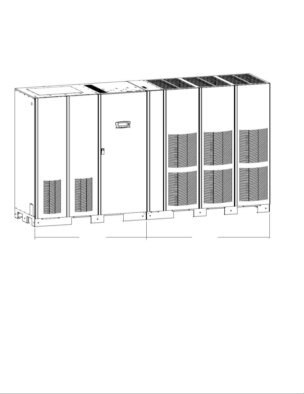
The Powerware 9395 UPS (650–825 kVA) contains two sections: an integrated
system bypass module (ISBM) or an Input Output Module (IOM) rated for a maximum
of 825 kVA and an Uninterruptible Power Module (UPM) section containing three
UPMs. Each UPM is rated for a maximum of 275 kVA for a total maximum of 825
kVA.
The UPS is available as a single unit or an optional multiple unit distributed bypass
system (see paragraph 1.2.7).
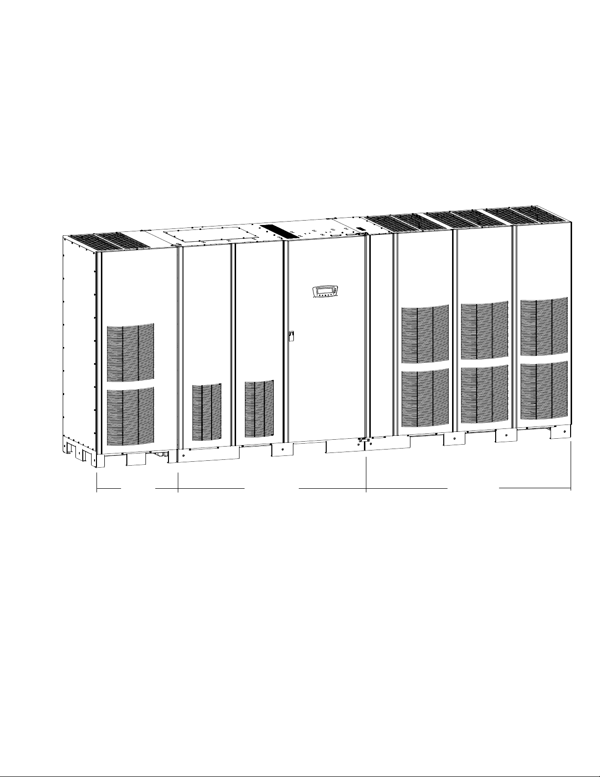
The UPS Plus 1 model using the Field Installed UPM (FI−UPM) provides N+1
redundancy for the system (see paragraph 1.2.1).
The Powerware 9395 online power protection system is used to prevent loss of
valuable electronic information, minimize equipment downtime, and minimize the
adverse effect on production equipment due to unexpected power problems.
The Powerware 9395 UPS continually monitors incoming electrical power and
removes the surges, spikes, sags, and other irregularities that are inherent in
commercial utility power. Working with a building’s electrical system, the UPS
system supplies clean, consistent power that sensitive electronic equipment requires
for reliable operation. During brownouts, blackouts, and other power interruptions,
batteries provide emergency power to safeguard operation.
The UPS is housed in a free-standing cabinet, divided into two sections to facilitate
shipping. The sections match in style and color and have safety shields behind the
doors for hazardous voltage protection. The FI−UPM matches the UPS in style and
color. Figure 1-1 shows the Powerware 9395 UPS (650–825 kVA). Figure 1-2 shows
the Powerware 9395 (650–825 kVA) UPS with the FI−UPM.
NOTE Startup and operational checks must be performed by an authorized Eaton Customer Service
Engineer, or the warranty terms specified on page W−1 become void. This service is offered as part of the
sales contract for the UPS. Contact an Eaton service representative in advance (usually a two−week notice is
required) to reserve a preferred startup date.
1.1 UPS Standard Features
The UPS has many standard features that provide cost-effective and consistently
reliable power protection. The descriptions in this section provide a brief overview of
the UPS standard features.
1.1.1 Installation Features
Each UPS section is shipped separately. The sections are mechanically and electrically
joined at the installation site.
Sections can be permanently bolted to the floor.
EATON Powerware® 9395 UPS (650–825 kVA) Installation and Operation Manual S 164201725 Rev 2 www.powerware.com
1−1
Page 12
INTRODUCTION
Power wiring can be routed through the top or bottom of the cabinet with
connections made to easily accessible terminals. Control wiring is routed through the
top of the cabinet and must be installed in accordance with Class 1 wiring methods.
1−2
ISBM SECTION
Figure 1-1. Powerware 9395 UPS (650–825 kVA)
UPM SECTION
1.1.2 Control Panel
The control panel, located on the front of the UPS, contains a liquid crystal display
(LCD) and pushbutton switches to control the operation of the UPS and to display the
status of the UPS system. See Chapter 7, UPS Operating Instructions," for
additional information.
1.1.3 Customer Interface
S Building Alarm Monitoring – Up to five inputs in the UPS are available to connect the
facility’s alarm system contacts. Some system configurations may limit the
number of inputs available. The UPS uses these inputs to monitor the building
alarms in addition to the UPS status. See Chapter 8, Communication," for
additional information.
EATON Powerware® 9395 UPS (650–825 kVA) Installation and Operation Manual S 164201725 Rev 2 www.powerware.com
Page 13
INTRODUCTION
S Alarm Contact – One alarm contact is provided for connection to equipment at the
facility, such as a light, an audible alarm, or a computer terminal. The equipment
connected to this contact alerts you to a UPS alarm. See Chapter 8,
Communication," for additional information.
S X−Slot Communication Bays – Four communication bays are standard equipment.
One to four optional X−Slot
at any time. X−Slot cards are quickly installed at the front of the UPS and are
hot−pluggable. See Chapter 8, Communication," for additional information.
®
connectivity cards can be installed in the UPS module
FI−UPM
ISBM SECTION
Figure 1-2. Powerware 9395 UPS (650–825 kVA) with the Field Installed UPM
UPM SECTION
1.1.4 Advanced Battery Management
A three−stage charging system increases battery service life by optimizing recharge
time, and protects batteries from damage due to high current charging and inverter
ripple currents. Charging at high currents can overheat and damage batteries.
1.1.5 Power Management Software
Powerware LanSafe® Power Management Software is bundled as part of the
Software Suite CD shipped with the UPS. See Chapter 8, Communication," for
additional information.
EATON Powerware® 9395 UPS (650–825 kVA) Installation and Operation Manual S 164201725 Rev 2 www.powerware.com
1−3
Page 14

INTRODUCTION
1.2 Options and Accessories
Contact an Eaton sales representative for information about the following options.
1.2.1 Field Installed UPM
A Field Installed UPM (FI−UPM) provides N+1 redundancy for the UPS system. The
FI−UPM may be installed at any time in the future when power needs change. The
module cabinet is installed on the left side of the ISBM section and is wired directly to
the UPS. No input or output wiring changes are needed for redundancy. Operation
remains the same as the original UPS.
1.2.2 Inherent Redundancy
To deliver greater reliability, the Powerware 9395 UPS can be configured by an
authorized Eaton Customer Service Engineer for inherent redundancy. When
configured, the UPS automatically becomes redundant if the load is at or below the
capacity of the UPMs minus the capacity of one UPM. Under normal conditions the
UPMs in the UPS share the load equally. If one or more UPMs becomes unavailable
and the load is at or below the capacity of remaining UPMs, the remaining UPMs
supply the load instead of transferring to bypass.
If the capacity of the UPMs falls below the redundancy level or the load increases
above redundancy level, but is still able to maintain the load, a loss of redundancy
alarm is sounded. If the load exceeds the capacity of remaining UPMs, the UPS
transfers to bypass.
1.2.3 Sync Control
An optional Powerware 9395 Sync Control maintains the critical load outputs of two
separate single module Powerware 9395 UPS systems in synchronization. This option
facilitates the uninterrupted transfer of the load from one load bus to another by
means of transfer switches. The Sync Control is housed in a wall-mounted panel that
can be located between the UPS units for easy wiring.
1.2.4 Monitoring and Communication
S Remote Monitor Panel II (RMP II) – An optional RMP II contains backlit status
indicators and a local horn, allowing monitoring of the operational status and alarm
condition of the UPS from virtually any location within the facility.
S Relay Interface Module II (RIM II) – An optional RIM II uses relay contact closures to
indicate the UPS operating status and alarm condition.
S Supervisory Contact Module II (SCM II) – An optional SCM II establishes an interface
between the UPS system equipment and the customer’s monitor.
S X−Slot Cards – Optional X−Slot cards support several protocols, such as SNMP,
HTTP, IBM
®
AS/400®, and Modbus®.
S eNotify Remote Monitoring and Diagnostics Service – An optional service that provides
24/7 remote monitoring of 43 alarms, temperature/humidity and battery charge
information, daily heartbeat check, and monthly report. The service also provides
customer notification of significant alarms, remote diagnostics, and dispatch of
technicians. A ConnectUPS−X Web/SNMP Card is required in an X−Slot
communication bay. An optional Powerware Environmental Monitoring Probe
(EMP) is required for temperature/humidity monitoring.
1−4
See Chapter 8, Communication," for additional information on monitoring and
communication features.
EATON Powerware® 9395 UPS (650–825 kVA) Installation and Operation Manual S 164201725 Rev 2 www.powerware.com
Page 15

1.2.5 Single−Feed Kit
An optional kit is available for converting the dual−feed rectifier and bypass inputs to a
single−feed configuration. The kit consists of jumpers for each phase, and the
hardware required for installation.
1.2.6 Separate Rectifier Input
The UPS can be supplied with separate rectifier inputs for each UPM. Separate inputs
provide increased flexibility and reliability by allowing multiple input sources to supply
the UPS. Input circuit breaker CB1 is not installed with this configuration. AC input
control to the UPS and each UPM rectifier is to be provided by the customer.
1.2.7 Distributed Bypass System
There are two types of redundancy: UPS based (based on the number of UPS units)
and UPM based (based on the number of UPMs). Each UPS can contain three to four
UPMs.
INTRODUCTION
1.2.8 Input Output Module Configuration
1.3 Battery System
A distributed bypass UPS system with two to five UPS units can be installed to
provide a capacity and/or redundant system. This load sharing system provides more
capacity than a single UPS, and can provide backup, depending on the load and
configuration. In addition, when one UPM is taken out of service for maintenance or is
not operating properly, a redundant UPM continues to supply uninterrupted power to
the critical load. A Powerware Hot Sync
®
Controller Area Network (CAN) Bridge Card
provides connectivity and operational mode control. The distributed bypass system
consists of two to five UPS units each with a parallel CAN card, and a
customer−supplied tie cabinet or load distribution panel to act as a tie point. The tie
cabinet should contain Module Output Breakers (MOBs) with dual auxiliary contacts
for control of the system.
The UPS can be supplied in an Input Output Module (IOM) configuration without the
bypass input connections, the static switch, the motorized wraparound bypass
breaker, and the backfeed protection contactor. This configuration is primarily used in
multiple UPS parallel systems that do not need a bypass for each UPS and use a
separate System Bypass Module (SBM) to provide system bypass capabilities.
Although not provided with the UPS, a battery system is required to provide
emergency short−term backup power to safeguard operation during brownouts,
blackouts, and other power interruptions. The battery system should be equipped
with lead-acid batteries. An external battery disconnect switch must be used.
The UPMs may be powered with either a common or separate battery system. In a
common battery system, single and multiple UPMs are powered from one common
battery source. In a separate battery system, multiple UPMs are each powered from
separate battery sources.
UPMs in distributed bypass and parallel systems must use a separate battery system.
A supplemental 48 Vdc shunt trip signal for the battery disconnect device is provided
by the UPS, but is not required for normal operation.
EATON Powerware® 9395 UPS (650–825 kVA) Installation and Operation Manual S 164201725 Rev 2 www.powerware.com
1−5
Page 16

INTRODUCTION
1.4 Basic System Configurations
The following basic UPS system configurations are possible:
S Single UPS with three common battery UPMs and a standalone common battery
system with a battery disconnect
S Single UPS with three common battery UPMs, a common battery FI−UPM, and a
standalone common battery system with a battery disconnect
S Single UPS with three separate battery UPMs and a standalone separate battery
system with a battery disconnect for each UPM
S Single UPS with three separate battery UPMs, a separate battery FI−UPM, and a
standalone separate battery system with a battery disconnect for each UPM
S Distributed bypass system with two to five UPSs and a customer−supplied
tie cabinet
The UPS system configuration can be enhanced by adding optional accessories such
as a Remote Emergency Power−off (REPO) control, RMP II, or X−Slot communication
cards.
1.5 Using This Manual
This manual describes how to install and operate the Powerware 9395 650–825 kVA
UPS. Read and understand the procedures described in this manual to ensure
trouble−free installation and operation. In particular, be thoroughly familiar with the
REPO procedure (see paragraph 7.3.11 on page 7−18).
The information in this manual is divided into sections and chapters. The system,
options, and accessories being installed dictate which parts of this manual should be
read. At a minimum, Chapters 1 through 4 and Chapter 7 should be examined.
Read through each procedure before beginning the procedure. Perform only those
procedures that apply to the UPS system being installed or operated.
1.6 Conventions Used in This Manual
This manual uses these type conventions:
S Bold type highlights important concepts in discussions, key terms in procedures,
and menu options, or represents a command or option that you type or enter at a
prompt.
S Italic type highlights notes and new terms where they are defined.
S Screen type represents information that appears on the screen or LCD.
Icon Description
1−6
Information notes call attention to important features or instructions.
[Keys] Brackets are used when referring to a specific key, such as [Enter] or [Ctrl].
In this manual, the term UPS refers only to the UPS cabinet and its internal elements.
The term UPS system refers to the entire power protection system – the UPS
cabinet, the battery system, and options or accessories installed.
EATON Powerware® 9395 UPS (650–825 kVA) Installation and Operation Manual S 164201725 Rev 2 www.powerware.com
Page 17
1.7 Symbols, Controls, and Indicators
The following are examples of symbols used on the UPS or accessories to alert you
to important information:
INTRODUCTION
RISK OF ELECTRIC SHOCK − Observe the warning associated with the risk of electric
shock symbol.
CAUTION: REFER TO OPERATOR’S MANUAL − Refer to your operator’s manual for
additional information, such as important operating and maintenance instructions.
1.8 For More Information
This symbol indicates that you should not discard the UPS or the UPS batteries in the
trash. This product contains sealed, lead-acid batteries and must be disposed of
properly. For more information, contact your local recycling/reuse or hazardous waste
center.
This symbol indicates that you should not discard waste electrical or electronic
equipment (WEEE) in the trash. For proper disposal, contact your local recycling/reuse
or hazardous waste center.
Refer to the Powerware 9390 and 9395 Sync Control Installation and Operation
Manual for the following additional information:
S Installation instructions, including site preparation, planning for installation, and
wiring and safety information. Detailed illustrations of the cabinet with dimensional
and connection point drawings are provided.
S Operation, including controls, functions of the standard and optional features,
procedures for using with the UPS, and information about maintenance.
Refer to the Powerware 9395 Field Installed UPM Mechanical Installation Manual for
the following additional information:
S Mechanical installation instructions, including site preparation, planning for
mechanical installation, and safety information.
S Detailed illustrations of the cabinet, including dimension and pallet removal
drawings.
Visit www.powerware.com or contact an Eaton service representative for information
on how to obtain copies of these manuals.
EATON Powerware® 9395 UPS (650–825 kVA) Installation and Operation Manual S 164201725 Rev 2 www.powerware.com
1−7
Page 18

INTRODUCTION
1.9 Getting Help
If help is needed with any of the following:
S Scheduling initial startup
S Regional locations and telephone numbers
S A question about any of the information in this manual
S A question this manual does not answer
Please call the Eaton Help Desk for Powerware products at:
United States:
Canada: 1−800−461−9166 ext 260
All other countries: Call your local service representative
1−800−843−9433 or 1−919−870−3028
1−8
EATON Powerware® 9395 UPS (650–825 kVA) Installation and Operation Manual S 164201725 Rev 2 www.powerware.com
Page 19

Chapter 2 Safety Warnings
Figure 2Table 2
IMPORTANT SAFETY INSTRUCTIONS
SAVE THESE INSTRUCTIONS
This manual contains important instructions that should be followed during installation and maintenance of
the UPS and batteries. Read all instructions before operating the equipment and save this manual for future
reference.
The UPS is designed for industrial or computer room applications, and contains safety shields behind the
door and front panels. However, the UPS is a sophisticated power system and should be handled with
appropriate care.
This UPS contains LETHAL VOLTAGES. All repairs and service should be performed by AUTHORIZED
SERVICE PERSONNEL ONLY. There are NO USER SERVICEABLE PARTS inside the UPS.
S The UPS is powered by its own energy source (batteries). The output terminals may carry live voltage
even when the UPS is disconnected from an AC source.
S To reduce the risk of fire or electric shock, install this UPS in a temperature and humidity controlled,
indoor environment, free of conductive contaminants. Ambient temperature must not exceed 40°C
(104°F). Do not operate near water or excessive humidity (95% maximum). The system is not intended for
outdoor use.
S Ensure all power is disconnected before performing installation or service.
S Batteries can present a risk of electrical shock or burn from high short-circuit current. The following
precautions should be observed: 1) Remove watches, rings, or other metal objects; 2) Use tools with
insulated handles; 3) Do not lay tools or metal parts on top of batteries; 4) Wear rubber gloves and boots.
S ELECTRIC ENERGY HAZARD. Do not attempt to alter any UPS or battery wiring or connectors. Attempting
to alter wiring can cause injury.
S Do not open or mutilate batteries. Released electrolyte is harmful to the skin and eyes. It may be toxic.
D A N G E R
W A R N I N G
C A U T I O N
S Installation or servicing should be performed by qualified service personnel knowledgeable of UPS and
battery systems, and required precautions. Keep unauthorized personnel away from equipment. Consider
all warnings, cautions, and notes before installing or servicing equipment. DO NOT DISCONNECT the
batteries while the UPS is in Battery mode.
S Replace batteries with the same number and type of batteries as originally installed with the UPS.
S Disconnect the charging source prior to connecting or disconnecting terminals.
S Determine if the battery is inadvertently grounded. If it is, remove the source of the ground. Contacting
any part of a grounded battery can cause a risk of electric shock. An electric shock is less likely if you
disconnect the grounding connection before you work on the batteries.
S Proper disposal of batteries is required. Refer to local codes for disposal requirements.
S Do not dispose of batteries in a fire. Batteries may explode when exposed to flame.
S Keep the UPS door closed and front panels installed to ensure proper cooling airflow and to protect
personnel from dangerous voltages inside the unit.
S Do not install or operate the UPS system close to gas or electric heat sources.
EATON Powerware® 9395 UPS (650–825 kVA) Installation and Operation Manual S 164201725 Rev 2 www.powerware.com
2−1
Page 20

SAFETY WARNINGS
S The operating environment should be maintained within the parameters stated in this manual.
S Keep surroundings uncluttered, clean, and free from excess moisture.
S Observe all DANGER, CAUTION, and WARNING notices affixed to the inside and outside of the
equipment.
C A U T I O N
To prevent damage to the wiring channel and wiring in the UPS cabinet base when lifting or moving the
cabinet:
S Lift and move the cabinet using only the front or rear forklift slots.
S Verify that the forklift forks are in a horizontal position before inserting them into the forklift slots.
DO NOT angle fork tips upward.
S Insert the forks all the way through the base. DO NOT insert forks partially into the base to move the
cabinet.
S Forks may be partially inserted into the front or rear forklift slots for minor positioning if the forks are
kept in a horizontal position with no upward angling.
S DO NOT use the forklift slots on the end of the cabinet to move the cabinet.
S End forklift slots may be used for minor positioning if the forks are kept in a horizontal position with no
upward angling.
If these instructions are not followed, damage to the wiring channel and wiring will occur.
A V E R T I S S E M E N T !
S Les batteries peuvent présenter un risque de décharge électrique ou de brûlure par des courts-circuits de
haute intensité. Prendre les précautions nécessaires.
S Pour le replacement, utiliser le même nombre et modéle des batteries.
A T T E N T I O N !
S Une mise au rebut réglementaire des batteries est obligatoire. Consulter les règlements en vigueur dans
votre localité.
S Ne jamais jeter les batteries au feu. L’exposition aux flammes risque de les faire exploser.
2−2
EATON Powerware® 9395 UPS (650–825 kVA) Installation and Operation Manual S 164201725 Rev 2 www.powerware.com
Page 21

Section I
Installation
EATON Powerware® 9395 UPS (650–825 kVA) Installation and Operation Manual S 164201725 Rev 2 www.powerware.com
2−1
Page 22

2−2
EATON Powerware® 9395 UPS (650–825 kVA) Installation and Operation Manual S 164201725 Rev 2 www.powerware.com
Page 23

Chapter 3 UPS Installation Plan and Unpacking
Figure 3Table 3
Use the following basic sequence of steps to install the UPS:
1. Create an installation plan for the UPS system (Chapter 3).
2. Prepare your site for the UPS system (Chapter 3).
3. Inspect and unpack the UPS sections (Chapter 3).
4. Unload and install the UPS sections, and wire the system (Chapter 4).
5. Install features, accessories, or options, as applicable (Chapter 5).
6. Complete the Installation Checklist (Chapter 4).
7. Have authorized service personnel perform preliminary operational checks and
start up the system.
NOTE Startup and operational checks must be performed by an authorized Eaton Customer Service
Engineer, or the warranty terms specified on page W−1 become void. This service is offered as part of the
sales contract for the UPS. Contact an Eaton service representative in advance (usually a two−week notice is
required) to reserve a preferred startup date.
3.1 Creating an Installation Plan
Before installing the UPS system, read and understand how this manual applies to the
system being installed. Use the procedures and illustrations in paragraph 3.2 and
Chapter 4 to create a logical plan for installing the system.
3.2 Preparing the Site
For the UPS system to operate at peak efficiency, the installation site should meet
the environmental parameters outlined in this manual. If the UPS is to be operated at
an altitude higher than 1500m (5000 ft), contact an Eaton service representative for
important information about high altitude operation. The operating environment must
meet the weight, clearance, and environmental requirements specified.
3.2.1 Environmental and Installation Considerations
The UPS system installation must meet the following guidelines:
S The system must be installed on a level floor suitable for computer or electronic
equipment.
S The system must be installed in a temperature and humidity controlled indoor area
free of conductive contaminants.
Failure to follow guidelines may void your warranty.
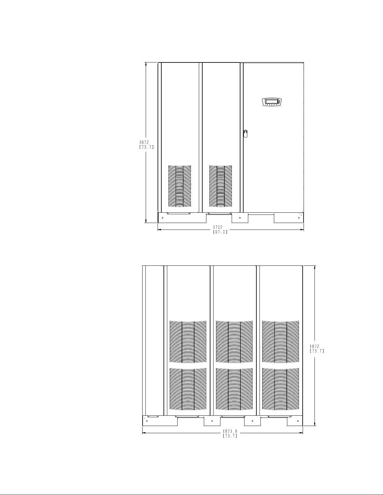
The UPS equipment operating environment must meet the weight requirements
shown in Table 3-1 and the size requirements shown in Figure 3-1 through
Figure 3-10. Dimensions are in millimeters (inches).
For Field Installed UPM (FI−UPM) weights and dimensions, refer to the Powerware
9395 Field Installed UPM Mechanical Installation Manual, listed in paragraph 1.8 on
page 1−7.
EATON Powerware® 9395 UPS (650–825 kVA) Installation and Operation Manual S 164201725 Rev 2 www.powerware.com
3−1
Page 24

UPS INSTALLATION PLAN AND UNPACKING
Table 3-1. UPS Cabinet Weights
Model Section
Weight
kg (lb)
Shipping Installed
Powerware 9395−825/650
Powerware 9395−825/750
Powerware 9395−825/825
ISBM 1498 (3302) 1390 (3064)
UPM 1590 (3505) 1482 (3267)
ISBM 1498 (3302) 1390 (3064)
UPM 1590 (3505) 1482 (3267)
ISBM 1498 (3302) 1390 (3064)
UPM 1590 (3505) 1482 (3267)
The UPS cabinet uses forced air cooling to regulate internal component temperature.
Air inlets are in the front of the cabinet and outlets are in the top. Allow clearance in
front of and above each cabinet for proper air circulation. The clearances required
around the UPS cabinet are shown in Table 3-2.
Table 3-2. UPS Cabinet Clearances
From Top of Cabinet 457.2 mm (18") minimum clearance for ventilation
From Front of Cabinet 914.4 mm (36") working space
From Back of Cabinet None Required
From Right Side of Cabinet 152.4 mm (6") working space
From Left Side of Cabinet None Required
The basic environmental requirements for operation of the UPS are:
S Ambient Temperature Range: 0–40°C (32–104°F)
S Recommended Operating Range: 20–25°C (68–77°F)
S Maximum Relative Humidity: 95%, noncondensing
C A U T I O N
If battery systems are located in the same room as the UPS, the battery manufacturer’s environmental
requirements should be followed if they are more stringent than the UPS requirements. Operating
temperatures above the recommended range will result in decreased battery life and performance, and may
reduce or void the battery warranty.
The UPS ventilation requirements are shown in Table 3-3.
Table 3-3. Air Conditioning or Ventilation Requirements During Full Load Operation
Rating
650 kVA
750 kVA
825 kVA
Input/Output
Voltage
400/400 125 (31613)
480/480 127 (31933)
400/400 145 (36476)
480/480 146 (36845)
400/400 159 (40124)
480/480 161 (40530)
Heat Rejection
BTU/hr 1000 (kg−cal/hr)
Ventilation Required for
Cooling Air Exhaust
Approximately 2265 liter/sec (4800 cfm)
With Field Installed UPM:
Approximately 3020 liter/sec (6400 cfm)
3−2
EATON Powerware® 9395 UPS (650–825 kVA) Installation and Operation Manual S 164201725 Rev 2 www.powerware.com
Page 25
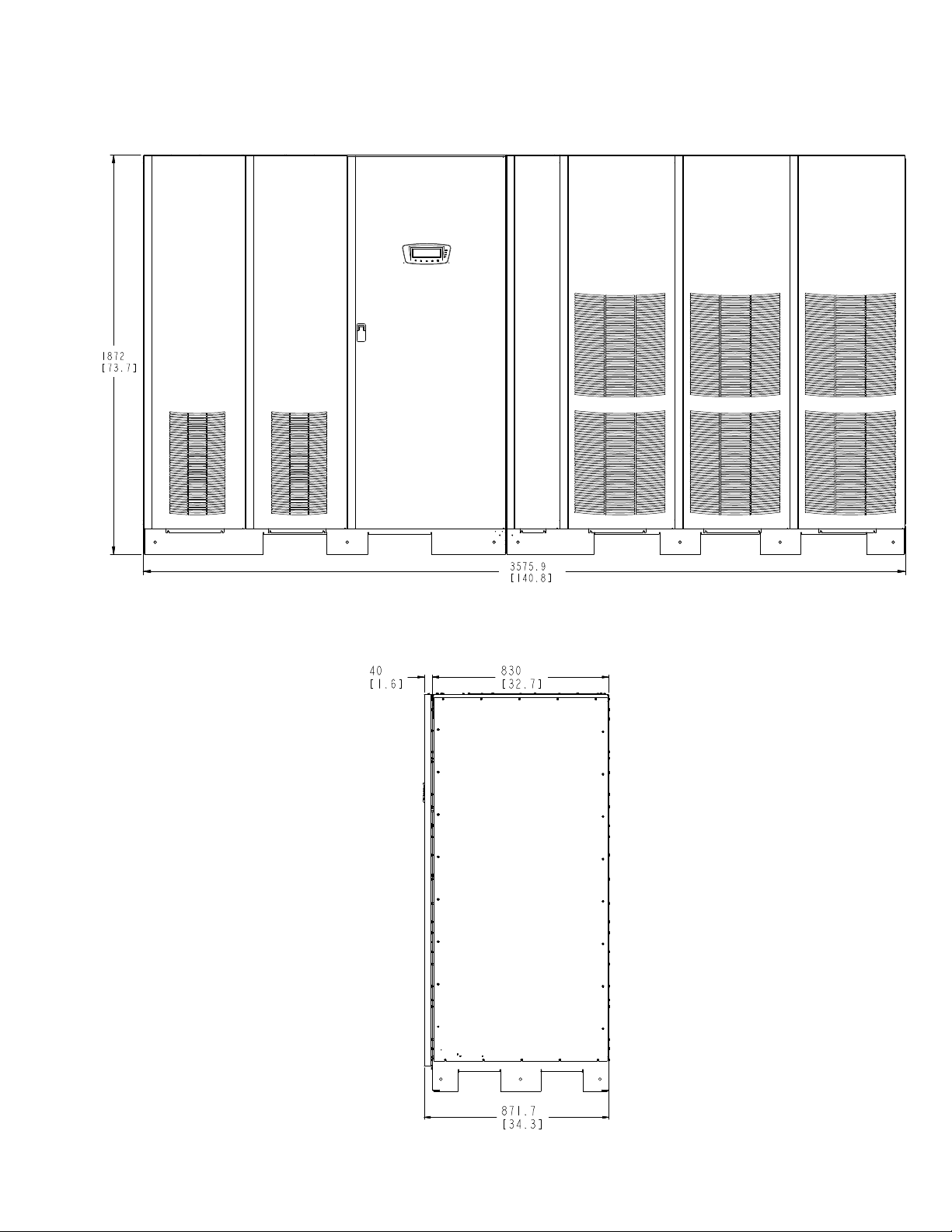
UPS INSTALLATION PLAN AND UNPACKING
Figure 3-1. UPS Cabinet Dimensions (Front View)
Dimensions are in millimeters [inches].
Dimensions are in millimeters [inches].
Figure 3-2. UPS Cabinet Dimensions (Right Side View)
EATON Powerware® 9395 UPS (650–825 kVA) Installation and Operation Manual S 164201725 Rev 2 www.powerware.com
3−3
Page 26
UPS INSTALLATION PLAN AND UNPACKING
Figure 3-3. ISBM Section Dimensions (Front View)
3−4
Figure 3-4. UPM Section Dimensions (Front View)
EATON Powerware® 9395 UPS (650–825 kVA) Installation and Operation Manual S 164201725 Rev 2 www.powerware.com
Page 27
UPS INSTALLATION PLAN AND UNPACKING
Front
Dimensions are in millimeters [inches].
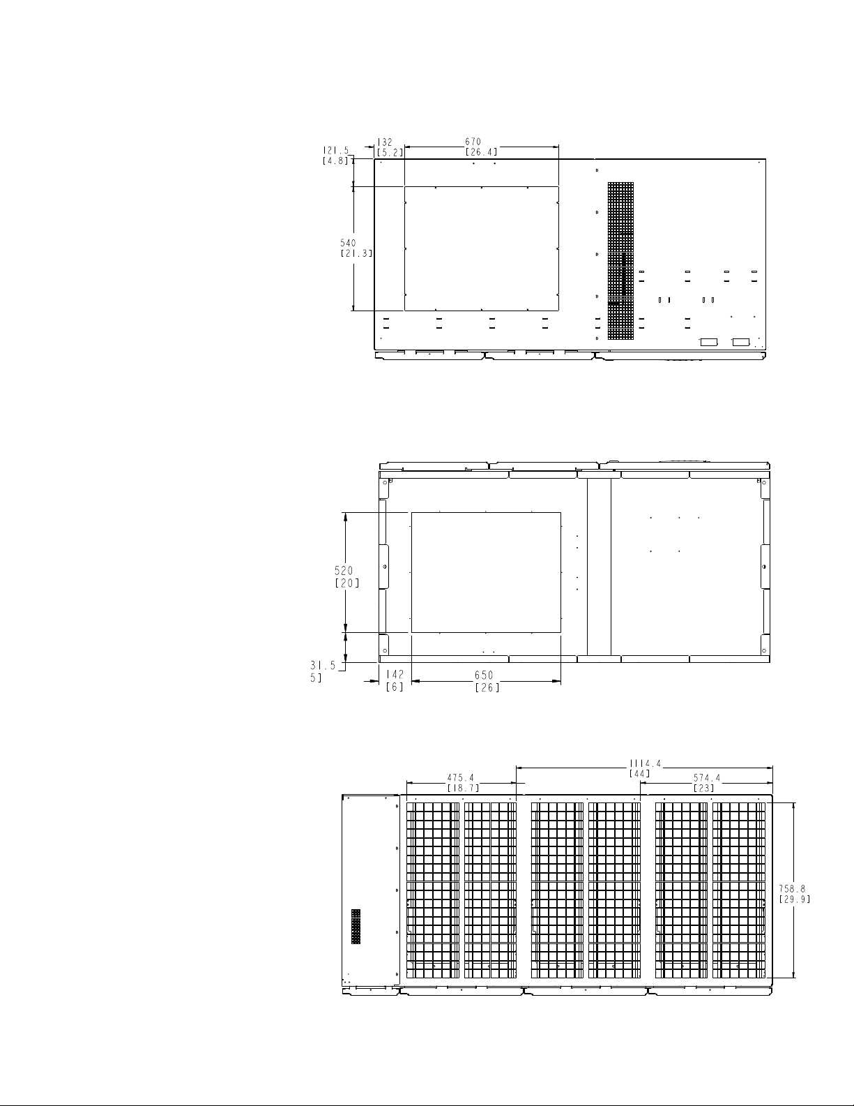
Figure 3-5. ISBM Section Dimensions (Top View)
Front
Dimensions are in millimeters [inches].
Figure 3-6. ISBM Section Dimensions (Bottom View)
Front
Dimensions are in millimeters [inches].
Figure 3-7. UPM Section Dimensions (Top View)
EATON Powerware® 9395 UPS (650–825 kVA) Installation and Operation Manual S 164201725 Rev 2 www.powerware.com
3−5
Page 28
UPS INSTALLATION PLAN AND UNPACKING
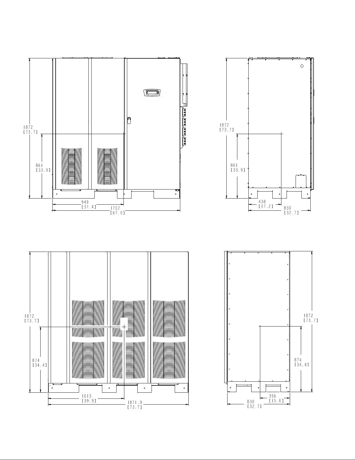
CG
Figure 3-8. ISBM Section Center of Gravity
CG
Dimensions are in millimeters [inches].
3−6
CG
CG
Dimensions are in millimeters [inches].
Figure 3-9. UPM Section Center of Gravity
EATON Powerware® 9395 UPS (650–825 kVA) Installation and Operation Manual S 164201725 Rev 2 www.powerware.com
Page 29
UPS INSTALLATION PLAN AND UNPACKING
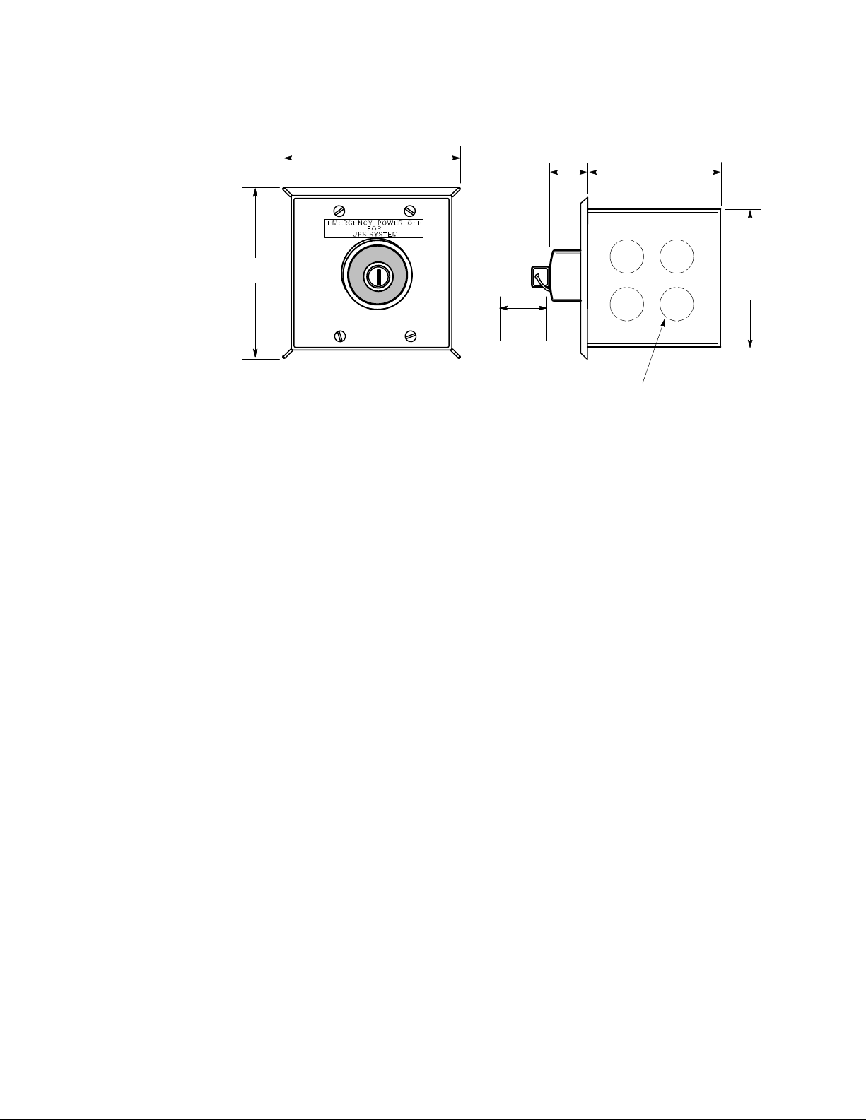
114.3
[4.50]
115.8
[4.56]
0.87
[0.22]
1.57
[0.40]
Needed to
Front View
remove key
Figure 3-10. Remote EPO Switch Dimensions
88.9
[3.50]
95.3
[3.57]
(Square)
1/2" Knockout Pattern
(Typical 5 Sides)
Dimensions are in millimeters [inches].
EATON Powerware® 9395 UPS (650–825 kVA) Installation and Operation Manual S 164201725 Rev 2 www.powerware.com
3−7
Page 30

UPS INSTALLATION PLAN AND UNPACKING
3.2.2 UPS System Power Wiring Preparation
Read and understand the following notes while planning and performing the
installation:
S Refer to national and local electrical codes for acceptable external wiring practices.
S To allow for future kVA upgrades, consider installing a derated UPS using wiring
S For external wiring, use 90°C copper or aluminum wire. Wire sizes listed in
S Wire ampacities are chosen from Table 310−16 of the NEC. Specification is for
S Material and labor for external wiring requirements are to be provided by
S If installing a maintenance bypass, a minimum of two separate feeds with
S The bypass feed into this equipment uses three or four wires. The rectifier feed
S If the load requires a neutral, a bypass source neutral must be provided. If the load
S The ISBM and UPM sections are shipped with debris shields covering the
S In a common battery system, single and multiple UPMs are powered from one
S On an UPS configured for separate rectifier inputs, all sources that feed the
S On an UPS configured as an Input Output Module (IOM), bypass input wiring,
S A Field Installed UPM (FI−UPM) is always designated as UPM 4.
and external overcurrent protection breakers sized for a fully rated UPS.
Table 3-4 and Table 3-5 are for copper wiring only. If wire is run in an ambient
temperature greater than 30°C, higher temperature wire and/or larger size wire
may be necessary. Wire sizes are based on using the specified breakers.
copper wire with a 90°C rating.
designated personnel.
upstream feeder breakers, or a single feed with two upstream feeder breakers,
must be provided: one for the UPS or rectifier input breaker (RIB) (if installed) and
one for the maintenance bypass input. DO NOT use a single feed or a single feeder
breaker to supply both the UPS or RIB and the maintenance bypass. If a bypass
input breaker (BIB) is installed in the maintenance bypass and a single−feed UPS is
being installed, a single feed to the maintenance bypass is acceptable for supplying
both the UPS and the bypass.
into this equipment uses three wires. The phases must be symmetrical about
ground (from a Wye source) for proper equipment operation.
does not require a neutral and there is no neutral conductor connected at the
bypass input, a neutral to ground bonding jumper must be installed. DO NOT install
both a source neutral and a bonding jumper. See Table 3-4 or Table 3-5 for neutral
bonding jumper wire sizes. The bonding jumper must be copper wire.
ventilation grills on top of the sections. Do not remove the debris shields until
installation is complete. However, remove the shields before operating the UPS.
Once the debris shields are removed, do not place objects on the ventilation grills.
common battery source. In a separate battery system, multiple UPMs are each
powered from separate battery sources.
separate rectifier inputs must be derived from a common ground point.
termination, conduit, and bypass breaker requirements are not applicable.
3−8
EATON Powerware® 9395 UPS (650–825 kVA) Installation and Operation Manual S 164201725 Rev 2 www.powerware.com
Page 31

UPS INSTALLATION PLAN AND UNPACKING
For external wiring requirements, including the minimum AWG size of external wiring,
see Table 3-4 for installations using a common battery system, Table 3-5 for
installations using a separate battery system, or Table 3-6 for separate rectifier feed
installations. Wire sizes listed are for copper wiring only.
Table 3-4. Input/Output Ratings and External Wiring Requirements for the Powerware 9395−825/650, 9395−825/750, and 9395−825/825
– Common Battery
Units Rating 50/60 Hz
Basic Unit Rating
Input and Output Voltage Volts 400/400 480/480 400/400 480/480 400/400 480/480
AC Input to UPS Rectifier (0.98 Minimum pF)
Full load current plus battery recharge current
(3) Phases, (1) Ground
Minimum Conductor Size
Number per Phase
AC Input to UPS Bypass (Four Wire)
Full Load Current
(3) Phases, (1) Ground
Minimum Conductor Size
Number per Phase
AC Input to UPS Bypass (Five Wire)
Full Load Current
(3) Phases, (1) Neutral, (1) Ground
Minimum Conductor Size
Number per Phase
DC Input from Battery Disconnect to UPS
(1) Positive, (1) Negative
Minimum Conductor Size
Number per Pole
AC Output to Critical Load (Four Wire)
Full Load Current
(3) Phases, (1) Ground
Minimum Conductor Size
Number per Phase
AC Output to Critical Load (Five Wire)
Full Load Current
(3) Phases, (1) Neutral, (1) Ground
Minimum Conductor Size
Number per Phase
Neutral Bonding Jumper (Four Wire Output Only)
Minimum Conductor Size
Number
NOTE Callout letters A, B, C, and D map to Figure 6-5, Figure 6-7, Figure 6-9, or Figure 6-11 starting on page 6−8.
A
B
B
C
D
D
–
kVA
kW
Amps 1079 891 1245 1028 1369 1130
AWG or kcmil
(each)
Amps 938 782 1083 902 1191 992
AWG or kcmil
(each)
Amps 938 782 1083 902 1191 992
AWG or kcmil
(each)
Total Amps 1280 1280 1502 1502 1600 1600
AWG or kcmil
(each)
Amps 938 782 1083 902 1191 992
AWG or kcmil
(each)
Amps 938 782 1083 902 1191 992
AWG or kcmil
(each)
AWG or kcmil
(each)
650
585
500
(4)
500
(3)
400
(4)
350
(6)
500
(3)
400
(4)
4/0
(1
650
591
500
(3)
350
(3)
500
(3)
350
(6)
350
(3)
500
(3)
4/0
(1)
750
675
500
(4)
500
(4)
500
(5)
500
(6)
500
(4)
500
(5)
4/0
(1
750
682
500
(4)
500
(3)
500
(4)
500
(6)
500
(3)
500
(4)
4/0
(1)
825
7742
500
(5)
500
(4)
500
(5)
500
(6)
500
(4)
500
(5)
4/0
(1
825
750
500
(4)
500
(4)
500
(5)
500
(6)
500
(4)
500
(5)
4/0
(1)
EATON Powerware® 9395 UPS (650–825 kVA) Installation and Operation Manual S 164201725 Rev 2 www.powerware.com
3−9
Page 32

UPS INSTALLATION PLAN AND UNPACKING
Table 3-5. Input/Output Ratings and External Wiring Requirements for the Powerware 9395−825/650, 9395−825/750, and 9395−825/825
– Separate Battery
Units Rating 50/60 Hz
Basic Unit Rating
Input and Output Voltage Volts 400/400 480/480 400/400 480/480 400/400 480/480
AC Input to UPS Rectifier (0.98 Minimum pF)
Full load current plus battery recharge current
(3) Phases, (1) Ground
Minimum Conductor Size
Number per Phase
AC Input to UPS Bypass (Four Wire)
Full Load Current
(3) Phases, (1) Ground
Minimum Conductor Size
Number per Phase
AC Input to UPS Bypass (Five Wire)
Full Load Current
(3) Phases, (1) Neutral, (1) Ground
Minimum Conductor Size
Number per Phase
DC Input from Each Battery Disconnect to Each UPS
UPM
(1) Positive, (1) Negative
Minimum Conductor Size
Number per Pole
AC Output to Critical Load (Four Wire)
Full Load Current
(3) Phases, (1) Ground
Minimum Conductor Size
Number per Phase
AC Output to Critical Load (Five Wire)
Full Load Current
(3) Phases, (1) Neutral, (1) Ground
Minimum Conductor Size
Number per Phase
Neutral Bonding Jumper (Four Wire Output Only)
Minimum Conductor Size
Number
NOTE Callout letter A,maps to Figure 6-6, Figure 6-8, Figure 6-10, or Figure 6-12 starting on page 6−9. Callout letters B, C, and D map to Figure 6-6,
Figure 6-8, Figure 6-10, Figure 6-12, Figure 6-13, Figure 6-14, Figure 6-15, or Figure 6-16 starting on page 6−9.
A
B
B
C
D
D
–
kVA
kW
Amps 1079 891 1245 1028 1369 1130
AWG or kcmil
(each)
Amps 938 782 1083 902 1191 992
AWG or kcmil
(each)
Amps 938 782 1083 902 1191 992
AWG or kcmil
(each)
Amps per UPM 551 551 551 551 551 551
AWG or kcmil
(each)
Amps 938 782 1083 902 1191 992
AWG or kcmil
(each)
Amps 938 782 1083 902 1191 992
AWG or kcmil
(each)
AWG or kcmil
(each)
650
585
500
(4)
500
(3)
400
(4)
250
(3)
500
(3)
400
(4)
4/0
(1)
650
591
500
(3)
350
(3)
500
(3)
250
(3)
350
(3)
350
(3)
4/0
(1)
750
675
500
(4)
500
(4)
500
(5)
250
(3)
500
(4)
500
(5)
4/0
(1)
750
682
500
(4)
500
(3)
500
(4)
250
(3)
500
(3)
500
(3)
4/0
(1)
825
742
500
(5)
500
(4)
500
(5)
250
(3)
500
(4)
500
(5)
4/0
(1)
825
750
500
(4)
500
(4)
500
(5)
250
(3)
500
(4)
500
(4)
4/0
(1)
3−10
EATON Powerware® 9395 UPS (650–825 kVA) Installation and Operation Manual S 164201725 Rev 2 www.powerware.com
Page 33

UPS INSTALLATION PLAN AND UNPACKING
AC input to the UPS with separate rectifier inputs is wired as if each UPM is rated for
275 kVA (see Table 3-6). The bypass input, battery input, and output are wired the
same as a separate battery UPS (see Table 3-5).
Table 3-6. Separate Rectifier Input UPM Ratings and External Wiring Requirements for the
Powerware 9395−825/650, 9395−825/750, and 9395−825/825 – Separate Battery
Units
Basic UPM Rating
Input Voltage Volts 400 480
AC Input to each UPM Rectifier (0.98 Min. pF)
Full load current plus battery recharge current
(3) Phases, (1) Ground
Minimum Conductor Size
Number per Phase
NOTE Callout letter A, maps to Figure 6-13 through Figure 6-16 starting on page 6−16.
A
kVA
kW
Amps 456 370
AWG or kcmil
(each)
Rating 50/60 Hz
275
247.5
2/0
(3)
275
250
4/0
(2)
EATON Powerware® 9395 UPS (650–825 kVA) Installation and Operation Manual S 164201725 Rev 2 www.powerware.com
3−11
Page 34

UPS INSTALLATION PLAN AND UNPACKING
Terminals E1A through E5A and E9A through E12A are stud type terminals. The
intercabinet power wiring connections for this equipment are rated at 90°C. See
Table 3-7 for intercabinet power cable terminations and Table 3-8 for supplied
intercabinet wiring terminal hardware.
Figure 4-8 through Figure 4-13 starting on page 4−11 show the location of the power
cable terminals inside the UPS.
Table 3-7. UPS Intercabinet Power Cable Terminations for the Powerware 9395−825/650, 9395−825/750, and 9395−825/825
Terminal Function Terminal Function Bus Landing
E1A (UPM 1)
AC Input to UPM Section
AC Output from UPM Section
DC Input to UPM Section
E1A (UPM 2)
E1A (UPM 3)
E1A (UPM 4 – Plus 1 Model)
E2A (UPM 1)
E2A (UPM 2)
E2A (UPM 3)
E2A (UPM 4 – Plus 1 Model)
E3A (UPM 1)
E3A (UPM 2)
E3A (UPM 3)
E3A (UPM 4 – Plus 1 Model)
E9A (UPM 1)
E9A (UPM 2)
E9A (UPM 3)
E10A (UPM 1)
E10A (UPM 2)
E10A (UPM 3)
E11A (UPM 1)
E11A (UPM 2)
E11A (UPM 3)
E12A (UPM 1)
E12A (UPM 2)
E12A (UPM 3)
1E4A (UPM 1)
2E4A (UPM 2)
3E4A (UPM 3)
1E5A (UPM 1)
2E5A (UPM 2)
3E5A (UPM 3)
Phase A 3 – stud mounting 12 (8.3) M8
Phase B 3 – stud mounting 12 (8.3) M8
Phase C 3 – stud mounting 12 (8.3) M8
Phase A 3 – stud mounting 12 (8.3) M8
Phase B 3 – stud mounting 12 (8.3) M8
Phase C 3 – stud mounting 12 (8.3) M8
Neutral 3 – stud mounting 12 (8.3) M8
Positive
Negative
6 – stud mounting
(2 per UPM)
6 – stud mounting
(2 per UPM)
Tightening Torque
Nm (lb ft)
12 (8.3) M8
12 (8.3) M8
Stud
Table 3-8. Supplied Intercabinet Wiring Terminal Hardware Kit
Part Size Quantity Terminals Used On Eaton Part Number
Flat Washer M8 36
Conical Washer M8 36
Nut M8 36
3−12
EATON Powerware® 9395 UPS (650–825 kVA) Installation and Operation Manual S 164201725 Rev 2 www.powerware.com
UPM AC Input, UPM Battery Input, UPM AC
Output, and Neutral
UPM AC Input, UPM Battery Input, UPM AC
Output, and Neutral
UPM AC Input, UPM Battery Input, UPM AC
Output, and Neutral
180500036−080
180500037−080
180200001−05
Page 35

UPS INSTALLATION PLAN AND UNPACKING
For an UPS with common rectifier input terminals, E1 through E12 are 2-hole bus bar
mountings for standard NEMA 2-hole barrel lugs. The power wiring connections for
this equipment are rated at 90°C. See Table 3-9 for external power cable terminations,
Table 3-10 for supplied external wiring terminal hardware, and Table 3-11 for
recommended installation parts and tools not supplied by Eaton Corporation.
For an UPS with separate rectifier input terminals for the UPMs, E1 through E3 are
pressure terminations, UL and CSA rated at 90°C. See Table 3-12 on page 3−14 for
these power cable terminations.
Figure 4-20 through Figure 4-26 starting on page 4−24 show the location of the power
cable terminals inside the UPS.
Table 3-9. UPS External Power Cable Terminations for the Powerware 9395−825/650, 9395−825/750, and 9395−825/825
Terminal Function Terminal Function
Bus Landings
(using both sides of bus)
Tightening Torque
Nm (lb ft)
Bolt Size
E1 Phase A 4 – 2 bolt mounting
AC Input to UPS Rectifier
AC Input to Bypass
AC Output to Critical Load
DC Input from Battery or Battery
Disconnect to UPS – Common
Battery
DC Input from Battery or Battery
Disconnect to UPS – Separate
Battery (UPM 1)
DC Input from Battery or Battery
Disconnect to UPS – Separate
Battery (UPM 2)
DC Input from Battery or Battery
Disconnect to UPS – Separate
Battery (UPM 3)
DC Input from Battery or Battery
Disconnect to UPS – Separate
Battery (UPM 4 FI−UPM)
Input and Output Neutral E12 Neutral 12 – 2 bolt mounting 22 (16) M10
Customer Ground Ground Ground 15 – 1 bolt mounting 22 (16) M10
NOTE Customer ground, sized in accordance with NEC Table 250.122, can be run in any conduit listed in Table 3-13 on page 3−15.
E2 Phase B 4 – 2 bolt mounting
E3 Phase C 4 – 2 bolt mounting
E6 Phase A 6 – 2 bolt mounting
E7 Phase B 6 – 2 bolt mounting
E8 Phase C 6 – 2 bolt mounting
E9 Phase A 6 – 2 bolt mounting
E10 Phase B 6 – 2 bolt mounting
E11 Phase C 6 – 2 bolt mounting
E4 Battery (+) 12 – 2 bolt mounting
E5 Battery (−) 12 – 2 bolt mounting
E4 Battery (+) 4 – 2 bolt mounting
E5 Battery (−) 4 – 2 bolt mounting
E4 Battery (+) 4 – 2 bolt mounting
E5 Battery (−) 4 – 2 bolt mounting
E4 Battery (+) 4 – 2 bolt mounting
E5 Battery (−) 4 – 2 bolt mounting
E4 Battery (+) 4 – 2 bolt mounting
E5 Battery (−) 4 – 2 bolt mounting
76 (56)
76 (56)
76 (56)
76 (56)
76 (56)
76 (56)
76 (56)
76 (56)
76 (56)
76 (56)
76 (56)
76 (56)
76 (56)
76 (56)
76 (56)
76 (56)
76 (56)
76 (56)
76 (56)
M12
M12
M12
M12
M12
M12
M12
M12
M12
M12
M12
M12
M12
M12
M12
M12
M12
M12
M12
EATON Powerware® 9395 UPS (650–825 kVA) Installation and Operation Manual S 164201725 Rev 2 www.powerware.com
3−13
Page 36

UPS INSTALLATION PLAN AND UNPACKING
Table 3-10. Supplied External Wiring Terminal Hardware Kit
Part Size Quantity Terminals Used On Eaton Part Number
Bolt, Grade 5 M10 x 25 mm 15 Ground 180190078−087
Bolt, Grade 5 M12 x 45 mm 92
Rectifier Input, Bypass Input, Battery Input,
Output, and Neutral
180190078−113
Flat Washer M10 15 Ground 180500036−100
Flat Washer M12 184
Rectifier Input, Bypass Input, Battery Input,
Output, and Neutral
180500036−120
Conical Washer M10 15 Ground 180500037−100
Conical Washer M12 92
Nut M12 92
Rectifier Input, Bypass Input, Battery Input,
Output, and Neutral
Rectifier Input, Bypass Input, Battery Input,
Output, and Neutral
180500037−120
180200001−07
Table 3-11. Recommended Installation Parts and Tools (Not Supplied by Eaton)
Part Size Quantity Manufacturer Part Number Notes
2/0 AWG
Thomas & Betts 54862BE
3/0 AWG Thomas & Betts 54864BE
4/0 AWG Thomas & Betts 54866BE
250 MCM Thomas & Betts 54868BE
Long Barrel 2-Hole Lug
300 MCM Thomas & Betts 54870BE
As required
Copper wire only
350 MCM Thomas & Betts 54872BE
400 MCM Thomas & Betts 54874BE
500 MCM Thomas & Betts 54876BE
Manual Hydraulic Crimp Tool 14 Ton 1 Thomas & Betts TBM14M
Die Set N/A 1 Thomas & Betts 15506
Table 3-12. Separate Rectifier Input UPM Power Cable Terminations for the Powerware 9395−825/650, 9395−825/750, and 9395−825/825
Terminal Function Terminal Function Size of Pressure Termination
E1 Phase A 2 − #6−250 kcmil
AC Input to each UPM Rectifier
E2 Phase B 2 − #6−250 kcmil
E3 Phase C 2 − #6−250 kcmil
Tightening Torque
Nm (lb ft)
42.4 (375)
42.4 (375)
42.4 (375)
Type Screw
5/16" Hex
5/16" Hex
5/16" Hex
3−14
EATON Powerware® 9395 UPS (650–825 kVA) Installation and Operation Manual S 164201725 Rev 2 www.powerware.com
Page 37

Conduit sizes were chosen from NEC Table 4, Electrical Metallic Tubing (EMT). See
Table 3-13 for conduit requirements.
Per NEC article 300, 3(B)(1), all three-phase conductors must be run in the same
conduit. Neutral and ground must be run in the same conduit as the phase
conductors.
Conduit is sized to accommodate one neutral conductor the same size as the phase
conductor and one ground conductor sized in accordance with NEC Table 250.122.
Conduit sizes listed are for copper wiring only.
Table 3-13. Power Cable Conduit Requirements
UPS Model Voltage Terminal
UPS INSTALLATION PLAN AND UNPACKING
Number of Wires
in Conduit
Minimum Conduit
Trade Size
Number of
Conduits
Powerware 9395−825/650
Powerware 9395−825/750
400 Vac
480 Vac
DC
400 Vac
480 Vac
DC
AC Input to UPS Rectifier
(A, B, C, Ground)
AC Input to UPS Rectifier (Separate Feed)
(A, B, C, Ground)
AC Input to Bypass and Output (Four Wire)
(A, B, C, Ground)
AC Input to Bypass and Output (Five Wire)
(A, B, C, Neutral, Ground)
AC Input to UPS Rectifier
(A, B, C, Ground)
AC Input to UPS Rectifier (Separate Feed)
(A, B, C, Ground)
AC Input to Bypass and Output (Four Wire)
(A, B, C, Ground)
AC Input to Bypass and Output (Five Wire)
(A, B, C, Neutral, Ground)
Battery
(Positive, Negative, Ground)
AC Input to UPS Rectifier
(A, B, C, Ground)
AC Input to UPS Rectifier (Separate Feed)
(A, B, C, Ground)
AC Input to Bypass and Output (Four Wire)
(A, B, C, Ground)
AC Input to Bypass and Output (Five Wire)
(A, B, C, Neutral, Ground)
AC Input to UPS Rectifier
(A, B, C, Ground)
AC Input to UPS Rectifier (Separate Feed)
(A, B, C, Ground)
AC Input to Bypass and Output (Four Wire)
(A, B, C, Ground)
AC Input to Bypass and Output (Five Wire)
(A, B, C, Neutral, Ground)
Battery
(Positive, Negative, Ground)
4 3 4
4 2
4 3 3
5 3 4
4 3 3
4 2
4 2-1/2 3
5 3 4
See Note
4 3 4
4 2
4 3 4
5 3 5
4 3 4
4 2
4 3 3
5 3 4
See Note
(Each UPM)
(Each UPM)
(Each UPM)
(Each UPM)
3
2
3
2
EATON Powerware® 9395 UPS (650–825 kVA) Installation and Operation Manual S 164201725 Rev 2 www.powerware.com
3−15
Page 38

UPS INSTALLATION PLAN AND UNPACKING
Table 3-13. Power Cable Conduit Requirements (continued)
TerminalVoltageUPS Model
Number of Wires
in Conduit
Minimum Conduit
Trade Size
Number of
Conduits
AC Input to UPS Rectifier
(A, B, C, Ground)
AC Input to UPS Rectifier (Separate Feed)
400 Vac
Powerware 9395−825/825
480 Vac
DC
NOTE Select conduit taking into consideration the DC input wire sizes listed in Table 3-4 on page 3−9 or Table 3-5 on page 3−10, the DC terminations
listed in Table 3-9 on page 3−13, type of battery installation, and requirements from NEC Table 4, Electrical Metallic Tubing (EMT).
AC Input to Bypass and Output (Four Wire)
AC Input to Bypass and Output (Five Wire)
AC Input to UPS Rectifier (Separate Feed)
AC Input to Bypass and Output (Four Wire)
AC Input to Bypass and Output (Five Wire)
(A, B, C, Ground)
(A, B, C, Ground)
(A, B, C, Neutral, Ground)
AC Input to UPS Rectifier
(A, B, C, Ground)
(A, B, C, Ground)
(A, B, C, Ground)
(A, B, C, Neutral, Ground)
Battery
(Positive, Negative, Ground)
4 3 5
4 2
4 3 4
5 3 5
4 3 4
4 2
4 3 4
5 3 5
See Note
(Each UPM)
(Each UPM)
3
2
External overcurrent protection and disconnect are not provided by this product, but
are required by codes. Refer to Table 3-4 on page 3−9, Table 3-5 on page 3−10, or
Table 3-6 on page 3−11 for wiring requirements. If an output lockable disconnect is
required, it is to be supplied by the customer.
3−16
Table 3-14 lists the recommended rating for input circuit breakers.
Table 3-15 lists the recommended rating for input circuit breakers with separate
rectifier inputs UPS. A separate breaker is required for each UPM.
Table 3-14. Recommended Input Circuit Breaker Ratings
UPS Model
Powerware 9395−825/650
Powerware 9395−825/750
Powerware 9395−825/825
EATON Powerware® 9395 UPS (650–825 kVA) Installation and Operation Manual S 164201725 Rev 2 www.powerware.com
Load Rating 400V 480V
80% Rated 1600A 1200A
100% Rated 1200A 1000A
80% Rated 1600A 1600A
100% Rated 1600A 1200A
80% Rated 2000A 1600A
100% Rated 1600A 1200A
Input Rating
Page 39

UPS INSTALLATION PLAN AND UNPACKING
Table 3-15. Separate Rectifier Input Recommended Input Circuit Breaker Ratings
UPS Model
Input Rating for Each UPM
Load Rating 480V
Powerware 9395−825/650
Powerware 9395−825/750
Powerware 9395−825/825
80% Rated 500A
100% Rated 400A
C A U T I O N
To reduce the risk of fire, connect only to a circuit provided with maximum input circuit breaker current
ratings from Table 3-14 in accordance with the NEC, ANSI/NFPA 70.
The line-to-line unbalanced output capability of the UPS is limited only by the full load
per phase current values for AC output to critical load shown in Table 3-4 on
page 3−9 or Table 3-5 on page 3−10. The recommended line-to-line load unbalance is
50% or less.
Bypass and output overcurrent protection and bypass and output disconnect switches
are to be provided by the customer. Module Output Breakers (MOBs) are to be
provided by the customer. Table 3-16 lists the recommended rating for bypass,
output, and MOB circuit breakers.
Table 3-16. Recommended Bypass, Output, and MOB Circuit Breaker Ratings
UPS Model
Powerware 9395−825/650
Load Rating 400V 480V
80% Rated 1200A 1000A
100% Rated 1000A 800A
Output Rating
Powerware 9395−825/750
Powerware 9395−825/825
80% Rated 1600A 1200A
100% Rated 1200A 1000A
80% Rated 1600A 1600A
100% Rated 1200A 1000A
EATON Powerware® 9395 UPS (650–825 kVA) Installation and Operation Manual S 164201725 Rev 2 www.powerware.com
3−17
Page 40

UPS INSTALLATION PLAN AND UNPACKING
There is no manual DC disconnect device within the UPS.
A battery disconnect switch is required for battery systems and may also be required
by NEC or local codes. The battery disconnect switch should be installed between the
battery and the UPS.
External DC input overcurrent protection and disconnect switch is to be provided by
the customer. Table 3-17 and Table 3-18 list the maximum ratings for continuous-duty
rated circuit breakers satisfying the criteria for both. Recommended disconnect size is
based on a maximum full load discharge time less than 3 hours. For longer discharge
times a larger disconnect may be required.
Table 3-17. Recommended DC Input Battery Disconnect Ratings – Common Battery
Input Rating
UPS Model
Powerware 9395−825/650 1600A 1600A
Powerware 9395−825/750 2000A 2000A
Powerware 9395−825/825 2000A 2000A
400V
480V
Table 3-18. Recommended DC Input Battery Disconnect Ratings – Separate Battery
Input Rating
UPS Model
Powerware 9395−825/650
Powerware 9395−825/750
Powerware 9395−825/825
400V
700A 700A
(each UPM)
480V
Battery voltage is computed at 2 volts per cell as defined by Article 480 of the NEC.
Rated battery current is computed at 2 volts per cell.
The battery wiring used between the battery and the UPS should not allow a voltage
drop of more than 1% of nominal DC voltage at rated battery current.
3−18
EATON Powerware® 9395 UPS (650–825 kVA) Installation and Operation Manual S 164201725 Rev 2 www.powerware.com
Page 41

UPS INSTALLATION PLAN AND UNPACKING
3.2.3 UPS System Interface Wiring Preparation
Control wiring for features and options should be connected at the customer interface
terminal blocks located inside the UPS.
W A R N I N G
Do not directly connect relay contacts to the mains related circuits. Reinforced insulation to the mains is
required.
Read and understand the following notes while planning and performing the
installation:
S Use Class 1 wiring methods (as defined by the NEC) for interface wiring up to 30V.
The wire should be rated at 24V, 1A minimum.
S Use Class 2 wiring methods (as defined by the NEC) for interface wiring from 30V
to 600V. The wire should be rated at 600V, 1A minimum and 12 AWG maximum.
S Use twisted-pair wires for each input and return or common.
S All interface wiring and conduit is to be provided by the customer.
S When installing external interface wiring (for example, building alarm, relay output,
battery breaker trip, and X−Slot) to the UPS interface terminals, conduit must be
installed between each device and the UPS cabinet.
S Install the interface wiring in separate conduit from the power wiring.
S When installing internal interface wiring to X−Slot terminals, route the wiring
through the internal opening in the X−Slot communication bay.
S All building alarm inputs or remote features require an isolated normally-open
contact or switch (rated at 24 Vdc, 20 mA minimum) connected between the alarm
input and common terminal. All control wiring and relay and switch contacts are
customer-supplied.
S The building alarms can be programmed to display the alarm functional name.
S LAN and telephone drops for use with X−Slot connectivity cards must be provided
by the customer.
S The UPS battery aux signal wiring from the UPS must be connected to the battery
disconnect device.
S A supplemental 48 Vdc shunt trip signal for the battery disconnect device is
provided, but is not required for normal operation.
S Battery aux and 48 Vdc shunt trip wiring should be a minimum of 18 AWG.
S The REPO feature opens all contactors in the UPS cabinet and isolates power from
your critical load. Local electrical codes may also require tripping upstream
protective devices to the UPS.
S The REPO switch must be a latching−type switch not tied to any other circuits.
S A jumper wire must be connected between pins 1 and 2 on TB1, if the
normally-closed REPO contact is not used.
S REPO wiring should be a minimum of 22 AWG and a maximum of 14 AWG.
EATON Powerware® 9395 UPS (650–825 kVA) Installation and Operation Manual S 164201725 Rev 2 www.powerware.com
3−19
Page 42

UPS INSTALLATION PLAN AND UNPACKING
S The REPO switch wiring must be in accordance with NEC Article 725 Class 2
S The maximum distance between the REPO and the UPS cannot exceed
S Alarm relay contacts have a maximum current rating of 5A and a switched voltage
S Alarm relay wiring should be a minimum of 22 AWG.
3.2.4 Distributed Bypass Power Wiring Preparation
Read and understand the following notes while planning and performing the
installation:
S All distributed bypass UPS rectifier inputs must come from one source and all
S Distributed bypass UPS input wiring size requirements and output wiring size
S If the load requires a neutral, a bypass source neutral must be provided. If the load
S The UPS cannot be installed in a high−resistance ground application.
S MOBs with dual auxiliary contacts are to be provided by the customer. Table 3-16
requirements.
150 meters (500 feet).
rating of 30 Vac and 28 Vdc.
bypass input feeds must come from one source.
requirements from the UPSs to the tie cabinet or distribution panel are the same as
listed in Table 3-4 on page 3−9 and Table 3-5 on page 3−10.
does not require a neutral and there is no neutral conductor connected at the
bypass input, a neutral to ground bonding jumper must be installed. Install neutral
conductors from the UPSs to the common point of connection (tie cabinet), and
then install a system neutral to ground bonding jumper. The bonding jumper must
be copper wire. DO NOT install both a source neutral and a bonding jumper.
If the recommended system neutral bonding jumper installation method cannot be
accomplished, each UPS should have a separate neutral to ground bonding jumper
installed. See Table 3-4 or Table 3-5 for UPS neutral bonding jumper wire sizes. The
bonding jumper must be copper wire. DO NOT install both a source neutral and a
bonding jumper.
on page 3−17 lists the recommended rating for the MOBs.
3−20
EATON Powerware® 9395 UPS (650–825 kVA) Installation and Operation Manual S 164201725 Rev 2 www.powerware.com
Page 43

3.3 Inspecting and Unpacking the UPS Cabinets
The UPS cabinet is divided into two sections palleted separately for shipping. The
sections are shipped bolted to wooden pallets (see Figure 3-11 and Figure 3-12) and
protected with outer protective packaging material.
The UPS sections are heavy (see Table 3-1 on page 3−2). If unpacking and unloading instructions are not
closely followed, the cabinets may tip and cause serious injury.
To prevent damage to the wiring channel and wiring in the UPM section base when lifting or moving the
cabinet:
S Lift and move the UPM section using only the front or rear forklift slots.
S Verify that the forklift forks are in a horizontal position before inserting them into the forklift slots.
DO NOT angle fork tips upward.
S Insert the forks all the way through the base. DO NOT insert forks partially into the base to move the
cabinet.
S Forks may be partially inserted into the front or rear forklift slots for minor positioning if the forks are
kept in a horizontal position with no upward angling.
S DO NOT use the forklift slots on the end of the cabinet to move the cabinet.
S End forklift slots may be used for minor positioning if the forks are kept in a horizontal position with no
upward angling.
If these instructions are not followed, damage to the wiring channel and wiring will occur.
UPS INSTALLATION PLAN AND UNPACKING
W A R N I N G
C A U T I O N
1. Carefully inspect the outer packaging for evidence of damage during transit.
C A U T I O N
Do not install a damaged cabinet. Report any damage to the carrier and contact an Eaton service
representative immediately.
NOTE For the following step, verify that the forklift or pallet jack is rated to handle the weight of the
cabinet (see Table 3-1 on page 3−2 for cabinet weight).
2. Use a forklift or pallet jack to move the packaged cabinets to the installation site,
or as close as possible, before unpacking. If possible, move the cabinets using
the pallet. Insert the forklift or pallet jack forks from the right side of the pallet
(facing the cabinet), between the supports on the bottom of the pallet (see
Figure 3-8 and Figure 3-9 on page 3−6 for the UPS cabinet center of gravity
measurements). If the cabinets must be moved using the cabinet front or rear
fork lift slots, see the caution statement at the beginning of this procedure.
C A U T I O N
Do not tilt the UPS cabinets more than 10° from vertical or the cabinets may tip over.
3. Set the pallet on a firm, level surface, allowing a minimum clearance of 3m (10 ft)
on each side for removing the cabinet from the pallet.
NOTE The ISBM and UPM sections are shipped with debris shields covering the ventilation grills on top of
the sections (see Figure 4-17 on page 4−19). Do not remove the debris shields until installation is complete.
EATON Powerware® 9395 UPS (650–825 kVA) Installation and Operation Manual S 164201725 Rev 2 www.powerware.com
3−21
Page 44

UPS INSTALLATION PLAN AND UNPACKING
4. Remove the protective covering from the cabinets.
5. Remove the packing material, and discard or recycle in a responsible manner.
6. Inspect the contents for any evidence of physical damage, and compare each
NOTE While waiting for installation, protect the unpacked cabinets from moisture, dust, and other harmful
contaminants. Failure to store and protect the UPS properly may void your warranty.
item with the Bill of Lading. If damage has occurred or shortages are evident,
contact an Eaton service representative immediately to determine the extent of
the damage and its impact on further installation.
3−22
Figure 3-11. UPS Cabinet as Shipped on Pallet (ISBM Section)
EATON Powerware® 9395 UPS (650–825 kVA) Installation and Operation Manual S 164201725 Rev 2 www.powerware.com
Page 45

UPS INSTALLATION PLAN AND UNPACKING
Figure 3-12. UPS Cabinet as Shipped on Pallet (UPM Section)
EATON Powerware® 9395 UPS (650–825 kVA) Installation and Operation Manual S 164201725 Rev 2 www.powerware.com
3−23
Page 46

UPS INSTALLATION PLAN AND UNPACKING
This page intentionally left blank.
3−24
EATON Powerware® 9395 UPS (650–825 kVA) Installation and Operation Manual S 164201725 Rev 2 www.powerware.com
Page 47

Chapter 4 UPS System Installation
Figure 4Table 4
4.1 Preliminary Installation Information
W A R N I N G
Installation should be performed only by qualified personnel.
Refer to the following while installing the UPS system:
S Chapter 3 for cabinet dimensions, equipment weight, wiring and terminal data, and
installation notes.
S Do not tilt the cabinets more than "10° during installation.
S Remove the conduit landing plates to add conduit landing holes as required. Plate
material is 16 gauge steel (1.5 mm/0.06" thick).
S If perforated floor tiles are required for ventilation, place them in front of the UPS.
4.2 Unloading the UPS Sections from the Pallet
The ISBM and UPM sections are bolted to separate wooden pallets supported by
wood skids. To remove the pallets:
W A R N I N G
The UPS sections are heavy (see Table 3-1 on page 3−2). If unpacking and unloading instructions are not
closely followed, the cabinets may tip and cause serious injury.
C A U T I O N
S Do not tilt cabinets more than 10° from vertical.
S Lift the cabinets only with a forklift or damage may occur.
To prevent damage to the wiring channel and wiring in the UPM section base when lifting or moving the
cabinet:
S Lift and move the UPM section using only the front or rear forklift slots.
S Verify that the forklift forks are in a horizontal position before inserting them into the forklift slots.
DO NOT angle fork tips upward.
S Insert the forks all the way through the base. DO NOT insert forks partially into the base to move the
cabinet.
S Forks may be partially inserted into the front or rear forklift slots for minor positioning if the forks are
kept in a horizontal position with no upward angling.
S DO NOT use the forklift slots on the end of the cabinet to move the cabinet.
S End forklift slots may be used for minor positioning if the forks are kept in a horizontal position with no
upward angling.
If these instructions are not followed, damage to the wiring channel and wiring will occur.
EATON Powerware® 9395 UPS (650–825 kVA) Installation and Operation Manual S 164201725 Rev 2 www.powerware.com
4−1
Page 48

UPS SYSTEM INSTALLATION
NOTE For the following steps, verify that the forklift or pallet jack is rated to handle the weight of the
cabinet (see Table 3-1 on page 3−2 for cabinet weight).
1. If not already accomplished, use a forklift or pallet jack to move the ISBM and
UPM sections to the installation area, or as close as possible, before unloading
from the pallets. If possible, move each section using the pallet. Insert the forklift
or pallet jack forks from the right side of the pallet (facing the cabinet), between
the supports on the bottom of the pallet (see Figure 3-8 and Figure 3-9 on
page 3−6 for the ISBM and UPM section center of gravity measurements). If the
sections must be moved using the cabinet front or rear fork lift slots, see the
caution statements at the beginning of this procedure.
2. Remove the three bolts securing the left side shipping bracket to the cabinet and
three bolts securing the bracket to the pallet (see Figure 4-1 or Figure 4-3).
Remove the left side shipping bracket.
3. Remove the three bolts securing the right side shipping bracket to the cabinet
and three bolts securing the bracket to the pallet (see Figure 4-2 or Figure 4-4).
Remove the right side shipping bracket.
Shipping Bracket
Bolts
Front Door
Pallet
4−2
Shipping Bracket
Bolts
Left Side Shipping
Bracket
Figure 4-1. Removing the ISBM Section Left Side Shipping Bracket
EATON Powerware® 9395 UPS (650–825 kVA) Installation and Operation Manual S 164201725 Rev 2 www.powerware.com
Page 49

ISBM Removable
Front Panels
UPS SYSTEM INSTALLATION
Pallet
Shipping Bracket
Bolts
Right Side Shipping
Bracket
Shipping Bracket
Bolts
Figure 4-2. Removing the ISBM Section Right Side Shipping Bracket
4. Using a forklift (see the caution statement at the beginning of this procedure),
raise the cabinet until the cabinet bottom clears the pallet by approximately
3 mm (1/8").
5. Pull the pallet from under the cabinet. Discard or recycle the pallet and shipping
brackets in a responsible manner.
6. Carefully lower the cabinet until the cabinet base contacts the floor.
7. Repeat Steps 2 through 6 for the remaining cabinet.
8. Proceed to paragraph 4.3.
EATON Powerware® 9395 UPS (650–825 kVA) Installation and Operation Manual S 164201725 Rev 2 www.powerware.com
4−3
Page 50
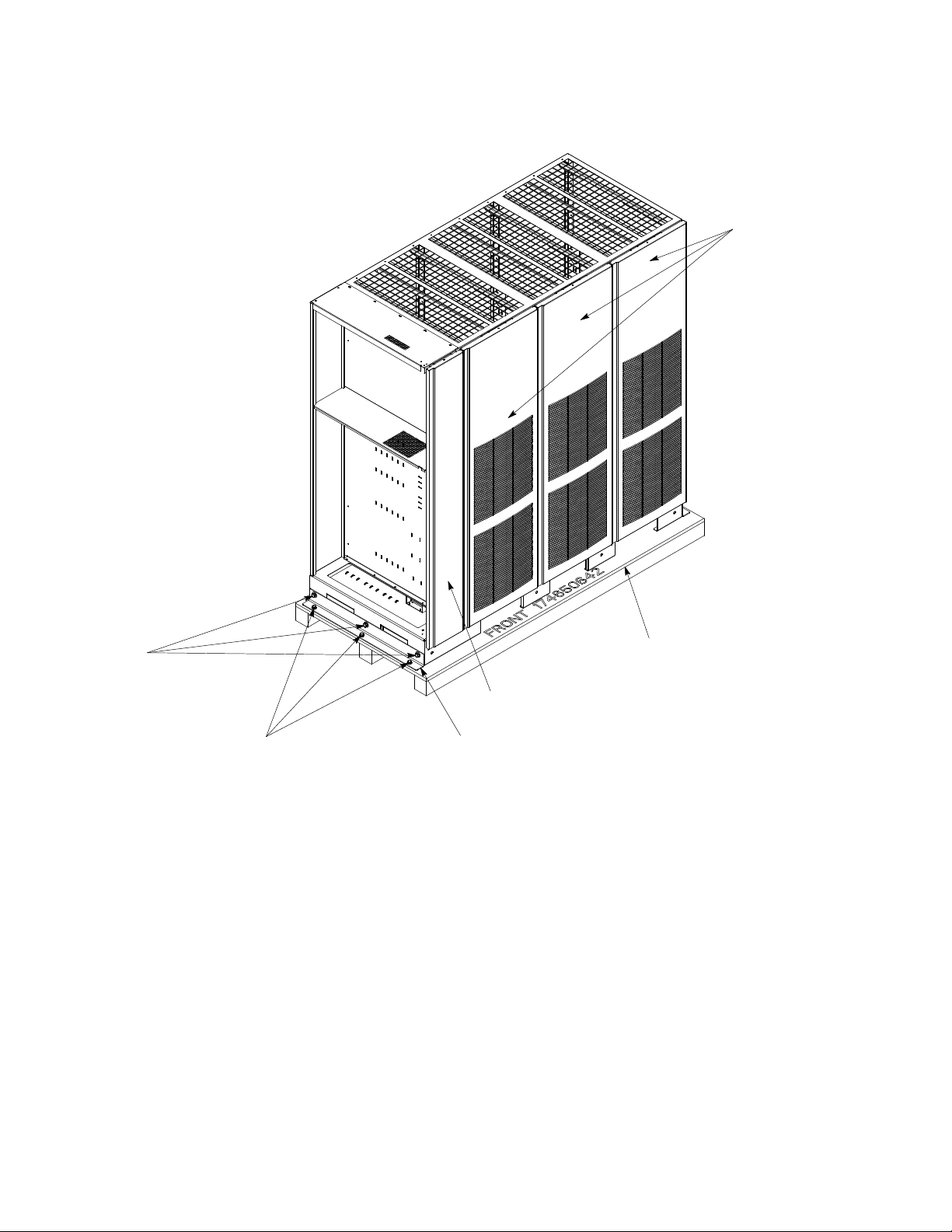
UPS SYSTEM INSTALLATION
UPM Removable
Front Panels
Shipping Bracket
Bolts
Shipping Bracket
Bolts
Pallet
Wireway Panel
Left Side Shipping
Bracket
Figure 4-3. Removing the UPM Section Left Side Shipping Bracket
4−4
EATON Powerware® 9395 UPS (650–825 kVA) Installation and Operation Manual S 164201725 Rev 2 www.powerware.com
Page 51

UPS SYSTEM INSTALLATION
Pallet
Right Side Shipping
Bracket
Figure 4-4. Removing the UPM Section Right Side Shipping Bracket
4.3 Mechanically Joining the Sections
NOTE The following procedure permits the UPS sections to be installed in a location where there is limited
space to slide the sections together from the sides.
NOTE For the following steps, verify that the forklift or pallet jack is rated to handle the weight of the
section (see Table 3-1 on page 3−2 for cabinet weight).
1. Using a forklift, move the UPM section to the final installed location.
2. Remove one top screw and two bottom screws securing the UPM section
wireway panel (see Figure 4-5). Lift the panel straight up to remove it from the
panel hanger brackets at the top of the cabinet.
Shipping Bracket
Bolts
Shipping Bracket
Bolts
3. Remove the screws securing the top and bottom internal safety shield panels
and remove the panels. Retain the hardware for later use.
4. Remove the screws securing the corner channel and remove the channel (see
Figure 4-5). Retain the hardware for later use.
EATON Powerware® 9395 UPS (650–825 kVA) Installation and Operation Manual S 164201725 Rev 2 www.powerware.com
4−5
Page 52

UPS SYSTEM INSTALLATION
Left Top Panel
Left Middle Panel
Interior Left
Side Panel
Corner Channel
UPM Section
Wireway Panel
Figure 4-5. Section Joining
5. Remove the screws securing the left top panel and remove the panel (see
Figure 4-5). Retain the hardware for later use.
6. Remove the screws securing the left middle panel and remove the panel (see
Figure 4-5). Retain the hardware for later use.
C A U T I O N
Use care during installation to protect components mounted on the right side of the ISBM section and the
intercabinet wiring harnesses attached to the left side UPM section from damage.
NOTE Clearance between the ISBM and the UPM sections must be less than 1/2" so that joining brackets
can be installed.
7. Using a forklift with the forks in the front forklift slots, position the ISBM section
adjacent to the left side of the previously installed UPM section. Verify that the
ISBM section right side is against the UPM section left side and the front of the
cabinet bases are flush with each other (see Figure 4-6).
4−6
8. Reinstall the corner channel (see Figure 4-5) and secure using the retained
hardware.
9. Reinstall the left middle panel (see Figure 4-5) and secure using the retained
hardware.
EATON Powerware® 9395 UPS (650–825 kVA) Installation and Operation Manual S 164201725 Rev 2 www.powerware.com
Page 53

UPS SYSTEM INSTALLATION
UPM Wireway
(Power wiring harnesses
are coiled in this area.)
Figure 4-6. ISBM and UPM Sections Joined
10. Reinstall the left top panel (see Figure 4-5) and secure using the retained
hardware.
NOTE Three flat cabinet joining brackets are provided in the hardware kit for securing the ISBM and UPM
sections at the top front, top rear, and front base (see Steps 11 and 12).
11. Locate the hardware kit (packed inside a drawstring bag tied to the left middle
panel of the UPM section). Locate two flat brackets and screws from the
hardware kit. Align the holes in the flat brackets over holes in the top rear and
top front of the ISBM and UPM sections. Secure the brackets with the screws
from the hardware kit (see Figure 4-7).
12. Locate one flat bracket and screws from the hardware kit. Align the holes in the
flat bracket over holes in the front base of the ISBM and UPM sections. Secure
the bracket with the screws from the hardware kit (see Figure 4-7).
13. Proceed to paragraph 4.4.
EATON Powerware® 9395 UPS (650–825 kVA) Installation and Operation Manual S 164201725 Rev 2 www.powerware.com
4−7
Page 54

UPS SYSTEM INSTALLATION
Bracket from Kit
ISBM
Section Top
Screw from Kit Screw from Kit
Front
Top View Front Bracket
Bracket from Kit
ISBM Section Base
UPM
Section Top
Bracket from Kit
ISBM
Section Top
Screw from Kit Screw from Kit
Back
UPM
Section Top
Top View Rear Bracket
UPM Section Base
Front View Base Bracket
Figure 4-7. ISBM Section to UPM Section Joining Brackets
4.4 Electrically Connecting the Sections
1. Unfasten the front door latch and swing the door open (see Figure 4-1 on
page 4−2).
2. Remove the door. Remove the retaining screw located inside the door at the
bottom hinge pivot point, then lift the door off. Retain the hardware for later use.
3. Remove the screws securing the ISBM section right bottom internal safety
shield panel and remove the panel to gain access to the internal input, output,
and battery terminals. Retain the hardware for later use.
NOTE AC and DC input intercabinet power wiring harnesses are supplied coiled and secured in the UPM
wireway on the left side of the UPM section (see Figure 4-6 on page 4−7).
4. Locate the AC and DC input intercabinet power wiring harnesses (long cables
labeled xG1, xG2, and xG3). Remove wire ties as necessary and uncoil the
cables.
5. Locate the 1G1, 1G2, 2G1, 2G2, 3G1, and 3G2 power wiring harnesses. Route
these harnesses through the wiring access in the right side panel of the ISBM
section to the AC Input to UPMs terminals. See Figure 4-8 on page 4−11 for
common rectifier feed terminal locations or Figure 4-10 on page 4−13 for separate
rectifier feed terminal locations.
Screw from KitScrew from Kit
4−8
EATON Powerware® 9395 UPS (650–825 kVA) Installation and Operation Manual S 164201725 Rev 2 www.powerware.com
Page 55

UPS SYSTEM INSTALLATION
NOTE Two cable lugs will be connected to each terminal stud. When connecting the cable lugs, install the
first lug on the stud with the raised barrel portion facing the back of the cabinet. Install the second lug with
the raised barrel portion facing the front of the cabinet.
6. Locate the intercabinet wiring terminal hardware kit packed on the bottom right
side of the ISBM section.
7. Using hardware from the intercabinet wiring terminal hardware kit (see Table 3-8
on page 3−12), connect phase A, B, and C cable lug connections to the AC Input
to UPMs terminals. Follow the callout details in Figure 4-9 on page 4−12 for
commom rectifier feed or Figure 4-11 on page 4−14 for separate rectifier feed to
connect the correct cable lug to the proper terminals. See paragraph 3.2.2 on
page 3−8 for wiring and termination requirements.
8. Locate the 1G3, 2G3, and 3G3 power wiring harnesses. Route these harnesses
through the wiring access in the right side panel of the ISBM section to the DC
Input to UPMs terminals. See Figure 4-8 on page 4−11 for common rectifier feed
terminal locations or Figure 4-10 on page 4−13 for separate rectifier feed terminal
locations.
NOTE When connecting the UPM battery cables, verify the cables are connected to the correct terminals .
9. Using hardware from the intercabinet wiring terminal hardware kit (see
Table 3-8), connect the positive and negative cable lug connections to the DC
Input to UPMs terminals. Follow the callout details in Figure 4-12 on page 4−15 to
connect the correct cable lug to the proper terminals. See paragraph 3.2.2 on
page 3−8 for wiring and termination requirements.
NOTE AC output intercabinet power wiring harnesses are supplied attached to the interior left side panel
of the UPM section (see Figure 4-5 on page 4−6).
10. Locate the 1G4, 1G5, 2G4, 2G5, 3G4, and 3G5 power wiring harnesses. Remove
the front two columns of wire ties securing the cables to facilitate routing cables
to the AC Output from UPMs terminals. See Figure 4-8 on page 4−11 for
common rectifier feed terminal locations or Figure 4-10 on page 4−13 for separate
rectifier feed terminal locations.
NOTE Two cable lugs will be connected to each terminal stud. When connecting the cable lugs, install the
first lug on the stud with the raised barrel portion facing the back of the cabinet. Install the second lug with
the raised barrel portion facing the front of the cabinet.
11. Using hardware from the intercabinet wiring terminal hardware kit (see
Table 3-8), connect phase A, B, and C and Neutral cable lug connections to the
AC Output from UPMs terminals. Follow the callout details in Figure 4-13 on
page 4−15 to connect the correct cable lug to the proper terminals. See
paragraph 3.2.2 on page 3−8 for wiring and termination requirements.
12. Install the remaining hardware (three washers, conical washers, and nuts) onto
the AC Input to UPMs terminals designated for the Plus 1 model and secure the
hardware (see Figure 4-9 on page 4−12 for common rectifier feed or Figure 4-23
on page 4−26 for separate rectifier feed). This hardware is for future use if a Field
Installed UPM (FI−UPM) is installed to upgrade the UPS to a Plus 1 model.
EATON Powerware® 9395 UPS (650–825 kVA) Installation and Operation Manual S 164201725 Rev 2 www.powerware.com
4−9
Page 56

UPS SYSTEM INSTALLATION
13. Locate the ground braid in the bottom left front corner of the UPM section. The
ground braid is secured at the factory to the UPM section ground bolt. Route the
ground braid through the wiring access in the right side panel of the ISBM
section to the ground bolt in the ISBM section.
14. Connect the ground braid to the ISBM section ground bolt and secure.
NOTE Four intercabinet interface wiring harnesses are supplied coiled inside the protective cage on the
right side panel of the ISBM section (see A in Figure 4-14 on page 4−16).
15. In the ISBM section (see A in Figure 4-14 on page 4−16), locate the coiled wiring
harnesses with the J50, J51, J61, and J70 connectors attached. Remove the
wire ties securing the harnesses and carefully remove the harnesses from the
protective cage. If necessary, loosen the screws securing the protective cage.
16. Locate the mating P50 connector in the UPM section wireway (see B in
Figure 4-14 on page 4−16) and connect the P50 connector to the J50 connector.
17. Locate the mating P51 connector in the UPM section wireway (see B in
Figure 4-14 on page 4−16) and connect the P51 connector to the J51 connector.
18. Locate the mating P61 connector in the UPM section wireway (see B in
Figure 4-14 on page 4−16) and connect the P61 connector to the J61 connector.
19. Locate the mating P70 connector in the UPM section wireway (see B in
Figure 4-14 on page 4−16) and connect the P70 connector to the J70 connector.
NOTE One intercabinet interface cable is supplied coiled against the left side panel of the UPM section
(see B in Figure 4-14 on page 4−16).
20. In the UPM section (see B in Figure 4-14 on page 4−16), locate the coiled RJ−45
CAN cable. Remove the wire ties securing the cable to the interior left side panel
of the UPM section. Route this harnesses through the round wiring access in the
right side panel of the ISBM section (see B in Figure 4-14 on page 4−16).
21. In the ISBM section, locate the J39 inverter CAN connector on the Pl1 interface
board and connect the RJ−45 CAN cable connector to the J39 connector (see
Figure 4-15 and Figure 4-16 on page 4−17).
22. Dress the interface harnesses and secure in place with wire ties as necessary to
prevent wire damage.
23. When all wiring is complete, reinstall the safety shield panels removed in
previous steps.
24. Reinstall the front wireway panel.
25. If installing a Plus 1 model UPS, proceed to paragraph 4.5; otherwise, proceed to
Step 26.
4−10
26. If installing a battery system, proceed to paragraph 4.6; otherwise, proceed to
Step 27.
27. If installing a tie cabinet or distribution panel for a distributed bypass system,
proceed to paragraph 4.7; otherwise, proceed to paragraph 4.8.
EATON Powerware® 9395 UPS (650–825 kVA) Installation and Operation Manual S 164201725 Rev 2 www.powerware.com
Page 57

UPS SYSTEM INSTALLATION
Phase A
AC Output
Phase B
from UPMs
(See Figure 4-13
for detail.)
Phase C
Neutral from UPMs
(See Figure 4-13 for detail.)
AC Input Breaker CB1
Phase C
Phase B
AC Input to UPMs
(See Figure 4-9
for detail.)
Phase A
–
DC Input to UPMs
(E5)
(See Figure 4-12 for detail.)
+
DC Input to UPMs
(E4)
(See Figure 4-12 for detail.)
Figure 4-8. ISBM Section Intercabinet Power Terminal Locations – Common Rectifier Feed
EATON Powerware® 9395 UPS (650–825 kVA) Installation and Operation Manual S 164201725 Rev 2 www.powerware.com
4−11
Page 58

UPS SYSTEM INSTALLATION
AC Input Breaker CB1
Phase B (E2A) – UPM 3 Cable 3G1 & 3G2 Brown
UPM 1 Cable 1G1 & 1G2 Brown
UPM 2 Cable 2G1 & 2G2 Brown
UPM 1 Cable 1G1 & 1G2 Yellow
UPM 3 Cable 3G1 & 3G2 Yellow
Phase A (E1A)
UPM 1 Cable 1G1 & 1G2 Orange
UPM 2 Cable 2G1 & 2G2 Orange
UPM 3 Cable 3G1 & 3G2 Orange
Phase A (E1A)
AC Input to
UPM 4 (FI−UPM)
Plus 1 Model
Phase B (E2A)
Phase C (E3A)
AC Input to UPMs
NOTE Two cable lugs will be connected to each terminal stud. When connecting the cable lugs, install the first lug on the stud with the raised
barrel portion facing the back of the cabinet. Install the second lug with the raised barrel portion facing the front of the cabinet.
NOTE On an UPS without CB1, UPM input wiring terminations are in the same positions on the bus bars installed in the place of CB1.
NOTE On an UPS configured as an Input Output Module (IOM), UPM input wiring terminations are the same as an ISBM configuration.
Phase B (E2A)
Phase C (E3A)UPM 2 Cable 2G1 & 2G2 Yellow
4−12
Figure 4-9. ISBM Section Input Power Terminal Detail – Common Rectifier Feed
EATON Powerware® 9395 UPS (650–825 kVA) Installation and Operation Manual S 164201725 Rev 2 www.powerware.com
Page 59

UPS SYSTEM INSTALLATION
Phase A
AC Output
Phase B
from UPMs
(See Figure 4-13
for detail.)
Phase C
Neutral from UPMs
(See Figure 4-13 for detail.)
Phase C
Phase B
AC Input to UPMs
(See Figure 4-9
for detail.)
Phase A
–
DC Input to UPMs
(E5)
(See Figure 4-12 for detail.)
DC Input to UPMs+(E4)
(See Figure 4-12 for detail.)
Figure 4-10. ISBM Section Intercabinet Power Terminal Locations – Separate Rectifier Feed
EATON Powerware® 9395 UPS (650–825 kVA) Installation and Operation Manual S 164201725 Rev 2 www.powerware.com
4−13
Page 60

UPS SYSTEM INSTALLATION
UPM 1 Cable 1G1 & 1G2 Brown – Phase B (E2A)
UPM 1 Cable 1G1 & 1G2 Orange
Phase A (E1A)
UPM 2 Cable 2G1 & 2G2 Orange
UPM 3 Cable 3G1 & 3G2 Orange
Phase B (E2A) – UPM 3 Cable 3G1 & 3G2 Brown
Phase A
Phase B Phase A
UPM 1 Cable 1G1 & 1G2 Yellow
UPM 2 Cable 2G1 & 2G2 Yellow
UPM 3 Cable 3G1 & 3G2 Yellow
UPM 2 Cable 2G1 & 2G2 Brown – Phase B (E2A)
AC Input to UPMs
NOTE Two cable lugs will be connected to each terminal stud. When connecting the cable lugs, install the first lug on the stud with the raised
barrel portion facing the back of the cabinet. Install the second lug with the raised barrel portion facing the front of the cabinet.
NOTE On an UPS without CB1, UPM input wiring terminations are in the same positions on the bus bars installed in the place of CB1.
NOTE On an UPS configured as an Input Output Module (IOM), UPM input wiring terminations are the same as an ISBM configuration.
Figure 4-11. ISBM Section Input Power Terminal Detail – Separate Rectifier Feed
Phase C (E3A)
4−14
EATON Powerware® 9395 UPS (650–825 kVA) Installation and Operation Manual S 164201725 Rev 2 www.powerware.com
Page 61

UPS SYSTEM INSTALLATION
s
DC Input to UPMs
+
UPM 1 (1E4A)
UPM 2 (2E4A)
UPM 3 (3E4A)
Cable 1G3 Red
Cable 1G3 Red
Cable 2G3 Red
Cable 2G3 Red
Cable 3G3 Red
Cable 3G3 Red
–
+
+
–
–
+
Cable 1G3 Black
Cable 1G3 Black
Cable 2G3 Black
Cable 2G3 Black
Cable 3G3 Black
Cable 3G3 Black
Figure 4-12. ISBM Section Battery Input Power Terminal Detail
UPM 1 Cable 1G4 & 1G5 Orange
UPM 2 Cable 2G4 & 2G5 Orange
Phase A (E9A)
UPM 3 Cable 3G4 & 3G5 Orange
UPM 1 (1E5A)
UPM 2 (2E5A)
UPM 3 (3E5A)
DC Input to UPM
–
UPM 1 Cable 1G4 & 1G5 Brown
UPM 2 Cable 2G4 & 2G5 Brown
Phase B (E10A)
AC Output
from UPMs
UPM 3 Cable 3G4 & 3G5 Brown
UPM 1 Cable 1G4 & 1G5 Yellow
UPM 2 Cable 2G4 & 2G5 Yellow
Phase C (E11A)
UPM 3 Cable 3G4 & 3G5 Yellow
UPM 1 Cable 1G4 & 1G5 Gray
UPM 2 Cable 2G4 & 2G5 Gray
Neutral from
UPMs (E12A)
UPM 3 Cable 3G4 & 3G5 Gray
NOTE Two cable lugs will be connected to each terminal stud. When connecting the cable lugs, install the first lug on the stud with the raised
barrel portion facing the back of the cabinet. Install the second lug with the raised barrel portion facing the front of the cabinet.
Figure 4-13. ISBM Section Output Power Terminal Detail
EATON Powerware® 9395 UPS (650–825 kVA) Installation and Operation Manual S 164201725 Rev 2 www.powerware.com
4−15
Page 62

UPS SYSTEM INSTALLATION
Protective Cage
Location of J50,
J51, J61, and J70
Coiled Harnesses
Wiring Access
Front
A
ISBM Section Right Side View
Location of P61
Harness
Front
UPM Wireway
Location of P50,
P51, and P70
Harnesses
Location of RJ−45
Coiled CAN Cable
B
UPM Section Left Side View
4−16
Figure 4-14. UPS Intercabinet Interface Harness Locations
EATON Powerware® 9395 UPS (650–825 kVA) Installation and Operation Manual S 164201725 Rev 2 www.powerware.com
Page 63

Pl1 Interface Board
Front
UPS SYSTEM INSTALLATION
ISBM Section Right Side Inside View
Figure 4-15. Pl1 Interface Board Location
Pl1 Interface Board
J39 Inverter CAN Connector
Figure 4-16. J39 Location on Pl1 Interface Board
EATON Powerware® 9395 UPS (650–825 kVA) Installation and Operation Manual S 164201725 Rev 2 www.powerware.com
4−17
Page 64

UPS SYSTEM INSTALLATION
4.5 Field Installed UPM Installation
If installing a Plus 1 model, install the FI−UPM using the instructions in the Powerware
9395 Field Installed UPM Mechanical Installation Manual, listed in paragraph 1.8 on
page 1−7. After the FI−UPM is installed, proceed to paragraph 4.6 if installing a battery
system; otherwise, proceed to paragraph 4.7.
4.6 Battery System Installation
If installing a battery system, install the customer−supplied battery system according
to the battery and battery system manufacturer’s instructions and all applicable codes
and regulations, including the National Electrical Code (NEC), Article 480. After the
battery system is installed, proceed to paragraph 4.7 if installing a distributed bypass
tie cabinet; otherwise, proceed to paragraph 4.8.
4.7 Distributed Bypass Tie Cabinet Installation
If installing a distributed bypass system, install the customer−supplied tie cabinet or
distribution panel according to the tie cabinet or distribution panel manufacturer’s
instructions and all applicable codes and regulations, including the National Electrical
Code (NEC), Article 480. After the tie cabinet is installed, proceed to paragraph 4.8 to
complete the wiring of the UPS.
4.8 Installing UPS External and Battery Power Wiring
NOTE The ISBM and UPM sections are shipped with debris shields covering the ventilation grills on top of
the sections (see Figure 4-17). Do not remove the debris shields until installation is complete. However,
remove the shields before operating the UPS. Once the debris shields are removed, do not place objects on
the ventilation grills.
NOTE Remove the ISBM section top or bottom conduit landing plate to drill or punch conduit holes (see
Figure 4-18 on page 4−20).
NOTE If the load requires a neutral, a bypass source neutral must be provided. If the load does not require
a neutral and there is no neutral conductor connected at the bypass input, a neutral to ground bonding jumper
must be installed. DO NOT install both a source neutral and a bonding jumper. See Table 3-4 on page 3−9 for
neutral bonding jumper wire sizes. Bonding jumper must be copper wire.
Use the procedures in the following paragraphs to connect the external and battery
power wiring.
4.8.1 External Power Wiring Installation
To install wiring to connections:
1. Remove one top screw and two bottom screws securing each ISBM section left
and right front panel (see Figure 4-2 on page 4−3). Lift the panels straight up to
remove them from the panel hanger brackets at the top of the cabinet.
2. Remove the screws securing the top and bottom internal safety shield panels
and remove the panels to gain access to the input, output, and battery terminals.
Retain the hardware for later use.
4−18
EATON Powerware® 9395 UPS (650–825 kVA) Installation and Operation Manual S 164201725 Rev 2 www.powerware.com
Page 65

ISBM Section
UPS SYSTEM INSTALLATION
Ventilation Grill Debris Shield
(Remove shield before operating system.)
UPM Section
Front
Ventilation Grill Debris Shields
(Remove shields before operating system.)
Front
Figure 4-17. ISBM and UPM Section Debris Shields
EATON Powerware® 9395 UPS (650–825 kVA) Installation and Operation Manual S 164201725 Rev 2 www.powerware.com
4−19
Page 66

UPS SYSTEM INSTALLATION
Top Entry Conduit Landing for AC
Input and Output, and DC Input
(Remove panel to drill or punch
conduit holes.)
TOP VIEW
Front
Interface Entry Conduit Landings for TB1
through TB3 Wiring and X−Slot Connections
(Remove panels to drill or punch conduit holes.)
BOTTOM VIEW
Bottom Entry Conduit Landing for AC
Input and Output, and DC Input
(Remove panel to drill or punch
conduit holes.)
Front
Figure 4-18. ISBM Section Conduit and Wire Entry Locations
3. Route the input and output cables through either the top or bottom of the cabinet
to the UPS terminals. See Figure 4-18 for wiring access information and
Figure 4-19 through Figure 4-21 for common rectifier feed terminal locations or
Figure 4-19, Figure 4-22, and Figure 4-23 for separate rectifier feed terminal
locations.
Top Access Wiring. Remove the top conduit plate from the top of the ISBM
section. Identify all conduit requirements and mark their location. Drill and punch
all conduit holes in the top conduit plate prior to mounting on the ISBM section.
Install the conduit plate and install all conduit runs into the plate. Pull wiring
through conduit into the ISBM section wiring area.
4−20
Bottom Access Wiring. Remove the bottom conduit plate from the inside bottom
of the ISBM section. Identify all conduit requirements and mark their location.
Drill and punch all conduit holes in the bottom conduit plate prior to mounting on
the ISBM section. Install the conduit plate and install all conduit runs into the
plate. Pull wiring through conduit into the ISBM section wiring area.
EATON Powerware® 9395 UPS (650–825 kVA) Installation and Operation Manual S 164201725 Rev 2 www.powerware.com
Page 67

UPS SYSTEM INSTALLATION
4. Locate the external wiring terminal hardware kit packed on the bottom left side
of the ISBM section.
5. If installing an UPS with separate rectifier feeds, proceed to Step 6; otherwise,
proceed to Step 8.
NOTE On an UPS that is configured for separate rectifier inputs all sources that feed the separate rectifier
inputs must be derived from a common ground point.
6. Connect phase A, B, and C rectifier input power wiring from the utility source to
each UPM rectifier input terminal block in the UPS cabinet. See paragraph 3.2.2
on page 3−8, Table 3-6 on page 3−11, and Table 3-12 on page 3−14 for wiring and
termination requirements.
7. Proceed to Step 9.
8. Using hardware from the external wiring terminal hardware kit (see Table 3-10 on
page 3−14), connect phase A, B, and C rectifier input power wiring from the utility
source to the rectifier input terminals in the ISBM section. See paragraph 3.2.2
on page 3−8 for wiring and termination requirements.
9. If installing an UPS configured as an Input Output Module (IOM), proceed to
Step 11; otherwise, proceed to Step 10.
10. Using hardware from the external wiring terminal hardware kit (see Table 3-10 on
page 3−14), connect phase A, B, and C, and Neutral (if required) bypass input
power wiring from the utility source to the bypass input terminals and neutral
terminals in the ISBM section. See paragraph 3.2.2 on page 3−8 for wiring and
termination requirements.
11. If wiring a distributed bypass system, proceed to Step 12; otherwise, proceed to
Step 14.
C A U T I O N
Distributed bypass system wiring length should be in accordance with Figure 4-19, to ensure approximately
equal current sharing when in Bypass mode.
12. Using hardware from the external wiring terminal hardware kit (see Table 3-10 on
page 3−14), connect phase A, B, and C, and Neutral power wiring from the output
and neutral terminals of each UPS unit to the customer−supplied tie cabinet or
load distribution panel. See paragraph 3.2.2 on page 3−8 for wiring and
termination requirements.
13. Proceed to paragraph 4.8.2.
14. Using hardware from the external wiring terminal hardware kit (see Table 3-10 on
page 3−14), connect phase A, B, and C, and Neutral (if required) power wiring
from output terminals and neutral terminals to the critical load. See
paragraph 3.2.2 on page 3−8 for wiring and termination requirements.
15. Proceed to paragraph 4.8.2.
EATON Powerware® 9395 UPS (650–825 kVA) Installation and Operation Manual S 164201725 Rev 2 www.powerware.com
4−21
Page 68

UPS SYSTEM INSTALLATION
Bypass Input to UPS Units
UPS 1
1A
2A
3A
4A
Battery
Battery
Battery
UPS 2
UPS 3
Output from UPS Units
1B
2B
UPS 4
3B
4B
Battery
NOTE Required parallel system wiring length must be equal to ensure approximately equal current sharing when in Bypass mode. For proper
operation the following must be true:
1A = 2A = 3A = 4A
1B = 2B = 3B = 4B
NOTE Any difference in wire length will result in decreased capacity of the UPS system while on bypass. For example, a 10% difference
between the longest and shortest wire lengths will result in a decrease in bypass capacity of 10%.
Figure 4-19. Distributed Bypass Wire Length
4−22
EATON Powerware® 9395 UPS (650–825 kVA) Installation and Operation Manual S 164201725 Rev 2 www.powerware.com
Page 69

AC Input to UPS Rectifier
(A, B, C)
(See Figure 4-21 for Detail AA.)
AC Input to UPS Bypass
(A, B, C)
(See Figure 4-21 for Detail AA.)
Phase C (E11)
AC Output to
Critical Load
Phase B (E10)
Phase A (E9)
UPS SYSTEM INSTALLATION
DC Input from Battery
+
(See Figure 4-25 or
Figure 4-26 for Detail BB.)
DC Input from Battery
–
(See Figure 4-25 or
Figure 4-26 for Detail BB.)
Neutral
(E12)
(E4)
(E5)
A
B
C
N
ISBM
NOTE AC Input to Bypass terminals are not applicable to an IOM configuration.
Figure 4-20. ISBM Section Power Terminal Locations – Common Rectifier Feed
EATON Powerware® 9395 UPS (650–825 kVA) Installation and Operation Manual S 164201725 Rev 2 www.powerware.com
4−23
Page 70

UPS SYSTEM INSTALLATION
Ground Terminals
Front
Phase C (E3)
Phase B (E2)
Phase A (E1)
Phase A (E6)
Phase B (E7)
Phase C (E8)
AC Input to
‘
UPS Rectifier
AC Input to
UPS Bypass
NOTE AC Input to Bypass terminals are not applicable to an IOM configuration.
Figure 4-21. ISBM Section Power Terminal Detail AA – Common Rectifier Feed
4−24
EATON Powerware® 9395 UPS (650–825 kVA) Installation and Operation Manual S 164201725 Rev 2 www.powerware.com
Section A–A
Page 71

AC Input to UPS Rectifier
(A, B, C)
(See Figure 4-23 for Detail AA.)
AC Input to UPS Bypass
(A, B, C)
(See Figure 4-23 for Detail AA.)
Phase C (E11)
AC Output to
Critical Load
Phase B (E10)
Phase A (E9)
UPS SYSTEM INSTALLATION
DC Input from Battery
+
(See Figure 4-25 or
Figure 4-26 for Detail BB.)
DC Input from Battery
–
(See Figure 4-25 or
Figure 4-26 for Detail BB.)
Neutral
(E12)
(E4)
(E5)
A
B
B
C
C
N
N
ISBM
NOTE AC Input to Bypass terminals are not applicable to an IOM configuration.
Figure 4-22. ISBM Section Power Terminal Locations – Separate Rectifier Feed
EATON Powerware® 9395 UPS (650–825 kVA) Installation and Operation Manual S 164201725 Rev 2 www.powerware.com
4−25
Page 72

UPS SYSTEM INSTALLATION
Ground Terminals
Section A–A
Front
‘
UPM Rectifier Input
Terminal Block
(See Figure 4-24 for Detail)
Phase A (E6)
Phase B (E7)
AC Input to
UPS Bypass
Phase C (E8)
NOTE AC Input to Bypass terminals are not applicable to an IOM configuration.
Figure 4-23. ISBM Section Power Terminal Detail AA – Separate Rectifier Feed
4−26
EATON Powerware® 9395 UPS (650–825 kVA) Installation and Operation Manual S 164201725 Rev 2 www.powerware.com
Page 73

AC Input to
UPM Rectifiers
UPS SYSTEM INSTALLATION
Phase A (E1)
Phase B (E2)
Phase C (E3)
UPM 1
UPM 2
UPM 2
Figure 4-24. UPM Rectifier Input Power Terminal Block Detail
UPM 4 (FIUPM) Plus 1 Model Only
Phase A (E1A)
Phase B (E2A)
Phase C (E3A)
AC Input to
UPM 4 (FI−UPM)
Plus 1 Model
EATON Powerware® 9395 UPS (650–825 kVA) Installation and Operation Manual S 164201725 Rev 2 www.powerware.com
4−27
Page 74

UPS SYSTEM INSTALLATION
4.8.2 Battery Power Wiring
C A U T I O N
When sizing the battery system, do not exceed the internal battery charger capabilities. See Chapter 10,
Product Specifications," for maximum battery charger currents.
To install wiring to connections:
NOTE An installed FI−UPM is always designated as UPM 4.
1. Route the battery cables between the ISBM section and the battery system or
battery disconnect. See Figure 4-18, Figure 4-20, Figure 4-25, and Figure 4-26 for
wiring access information and terminal locations.
2. If wiring the UPS for a common battery, proceed to Step 3; if wiring for a
separate battery, proceed to Step 5.
3. Using hardware from the external wiring terminal hardware kit (see Table 3-10 on
page 3−14), connect the positive, negative, and ground DC power wiring from the
battery system or disconnect to the ISBM section battery and ground terminals.
Use both sets of terminals shown in Figure 4-25 as needed. See paragraph 3.2.2
on page 3−8 for wiring and termination requirements.
4. Proceed to Step 6.
5. Using hardware from the external wiring terminal hardware kit (see Table 3-10 on
page 3−14), connect the positive, negative, and ground DC power wiring from the
battery systems or disconnects to the ISBM section battery and ground
terminals. Use one set of terminals for each UPM as shown in Figure 4-26. See
paragraph 3.2.2 on page 3−8 for wiring and termination requirements.
6. After wiring the UPS system to the facility power and critical load, be sure to
ground the system according to local and/or national electrical wiring codes.
7. If wiring interface connections, proceed to paragraph 4.9; otherwise, proceed to
Step 8.
8. When all wiring is complete, reinstall the top and bottom safety shield panels
removed in paragraph 4.8.1, Step 2 on page 4−18. Secure with the retained
hardware.
9. Reinstall the left front panel removed in paragraph 4.8.1, Step 1 on page 4−18 and
secure with the retained hardware.
4−28
EATON Powerware® 9395 UPS (650–825 kVA) Installation and Operation Manual S 164201725 Rev 2 www.powerware.com
Page 75

UPS SYSTEM INSTALLATION
DC Input from Battery +
DC Input from Battery
(E4)
Front
–
(E5)
Section B–B
Figure 4-25. ISBM Section Power Terminal Detail BB – Common Battery
EATON Powerware® 9395 UPS (650–825 kVA) Installation and Operation Manual S 164201725 Rev 2 www.powerware.com
4−29
Page 76

UPS SYSTEM INSTALLATION
DC Input from Battery +
DC Input from Battery +
DC Input from Battery
DC Input from Battery
DC Input from Battery
DC Input from Battery
DC Input from Battery
DC Input from Battery
(E4)
(E4)
+
(E4)
+
(E4)
(UPM 4 – FI−UPM)
–
(E5)
–
(E5)
(UPM 1)
–
(E5)
(UPM 2)
–
(E5)
(UPM 3)
(UPM 3)
(UPM 2)
(UPM 1)
(UPM 4 – FI−UPM)
Front
4−30
Section B–B
Figure 4-26. ISBM Section Power Terminal Detail CC – Separate Battery
EATON Powerware® 9395 UPS (650–825 kVA) Installation and Operation Manual S 164201725 Rev 2 www.powerware.com
Page 77

4.9 Installing Interface Connections
Hazardous voltages are present near the user interface terminal area if the UPS is not totally disconnected.
Use the procedures in the following paragraphs to connect the TB1, TB1 Battery,
TB2, and TB3 interface connections.
4.9.1 TB1, TB2, and TB3 Connections (Other than TB1 Battery Interface Connections)
NOTE When installing interface wiring for TB1, TB2, and TB3 connections, conduit must be installed
between each device and the UPS cabinet.
NOTE Interface wiring must be installed from the top of the UPS cabinet.
To install wiring to connections:
W
A R N I N G
UPS SYSTEM INSTALLATION
1. Verify the UPS system is turned off and all power sources are removed. See
Chapter 7, UPS Operating Instructions," for shutdown instructions.
2. If not already opened, unfasten the front door latch and swing the door open (see
Figure 4-1 on page 4−2).
3. If not already removed, remove the door. Remove the retaining screw located
inside the door at the bottom hinge pivot point, then lift the door off. Retain the
hardware for later use.
4. Terminal block TB3 is accessible on the left side of the X−Slot communication
bay. To gain access to terminal block TB1, TB2, and the left interface entry
conduit landing plates, remove the screws securing the top internal safety shield
panel and remove the panel. Retain the hardware for later use (see Figure 4-27
on page 4−32).
5. Remove the interface entry conduit landing plates to drill or punch holes (see
Figure 4-18 on page 4−20).
6. Reinstall the interface entry plates and install the conduit.
W A R N I N G
Do not directly connect relay contacts to the mains related circuits. Reinforced insulation to the mains is
required.
7. To locate the appropriate terminals and review the wiring and termination
requirements, see paragraph 3.2.3 on page 3−19, Table 4-1 on page 4−33, and
Figure 4-27 through Figure 4-30.
8. Route and connect the wiring.
9. If wiring TB1 battery interface connections, proceed to paragraph 4.9.2; if wiring
the X−Slot connections only, proceed to paragraph 4.9.3; otherwise, proceed to
Step 10.
10. Reinstall the top internal safety shield panel and secure with the retained
hardware.
EATON Powerware® 9395 UPS (650–825 kVA) Installation and Operation Manual S 164201725 Rev 2 www.powerware.com
4−31
Page 78

UPS SYSTEM INSTALLATION
11. Reinstall the front door removed in Step 3 and secure with the retained
hardware.
12. Close the door and secure the latch.
TB1 and TB2
(See Figure 4-28
for detail.)
X−Slot Communication Bays
(See Figure 4-33 on
page 4−38 for detail.)
TB3
(See Figure 4-30 on
page 4−35 for terminal
assignments.)
4−32
ISBM
Figure 4-27. ISBM Section Interface Terminal Locations
EATON Powerware® 9395 UPS (650–825 kVA) Installation and Operation Manual S 164201725 Rev 2 www.powerware.com
Page 79

Table 4-1. TB1, TB2, and TB3 Interface Connections
Terminal TB1 Name Description
UPS SYSTEM INSTALLATION
1 REPO NC
2 REPO Return
Input: Normally-closed dry contact used to activate UPS EPO from a remote switch.
3 REPO NO
4 REPO Return
5 Battery Aux
6 Battery Aux Common
Input: Normally-open dry contact used to activate UPS EPO from a remote switch.
Input: Normally-open contact used to indicate when UPS battery breaker is open or
closed.
7 48 Vdc Battery Shunt Trip +
8 48 Vdc Battery Shunt Trip –
Output: Contacts used to open battery breaker or disconnect.
9 Output Contactor K3 NC Aux
10
Output Contactor K3 NC Aux
Common
Output: Normally-closed contact opens when output contactor closes.
Terminal TB2 Name Description
1 Pull Chain
2 Pull Chain Common
Output: Backup control for parallel operation.
3 Alarm Relay NC
4 Alarm Relay Common
Output: General purpose normally−closed (NC) relay contact.
5 Alarm Relay NO
6 Alarm Relay Common
Output: General purpose normally−open (NO) relay contact.
7 Not Used
8 Not Used
9 Not Used
10 Not Used
Terminal TB3 Name Description
1 Building Alarm 1
2 Building Alarm 1 Return
Input: Programmable UPS alarm, activated by a remote dry contact closure.
3 Building Alarm 2
4 Building Alarm 2 Return
5
Building Alarm 3
Default: Charger Off
6 Building Alarm 3 Return
7
Building Alarm 4
Default: On Generator
8 Building Alarm 4 Return
9
Building Alarm 5
Default: Maintenance Bypass
10 Building Alarm 5 Return
Input: Programmable UPS alarm, activated by a remote dry contact closure.
Input: Programmable UPS alarm, activated by a remote dry contact closure. Default
function set for charger off.
Input: Programmable UPS alarm, activated by a remote dry contact closure. Default
function set for on generator.
Input: Programmable UPS alarm, activated by a remote dry contact closure. Default
function set for maintenance bypass.
NOTE Return indicates connection to electronics circuit ground. Common" indicates connection to common side of isolated relay contact.
EATON Powerware® 9395 UPS (650–825 kVA) Installation and Operation Manual S 164201725 Rev 2 www.powerware.com
4−33
Page 80

UPS SYSTEM INSTALLATION
X−Slot Communication Bays
TB1
TB2
See Figure 4-30
for terminal
assignments.
Figure 4-28. Interface Terminal Detail
TB2
3
4
Alarm Relay NC
Alarm Relay Common
Alarm Relay
5
6
Alarm Relay NO
Alarm Relay Common
NOTE Alarm relay contacts have a maximum current rating of 5A and a
switched voltage rating of 30 Vac and 28 Vdc.
NOTE Alarm relay normally−open and normally−closed return terminals
are separated on the terminal board but are electrically in common.
NOTE Do not directly connect relay contacts to the mains related
circuits. Reinforced insulation to the mains is required.
NOTE Alarm relay wiring should be a minimum of 22 AWG
.
Figure 4-29. Typical Alarm Relay Connection
4−34
EATON Powerware® 9395 UPS (650–825 kVA) Installation and Operation Manual S 164201725 Rev 2 www.powerware.com
Page 81

TB1
TB2
10
10
UPS SYSTEM INSTALLATION
UPS
REPO NC
REPO Return
REPO NO
1
REPO Return
Battery Aux
Battery Aux Common
Battery Shunt Trip +
Battery Shunt Trip –
Output Contactor K3 NC Aux
Output Contactor K3 NC Aux Common
1
Pull Chain
Pull Chain Common
Alarm Relay NC
Alarm Relay Common
Alarm Relay NO
Alarm Relay Common
UPS
Building Alarm 1
1
Building Alarm 1 Return
Building Alarm 2
Building Alarm 2 Return
TB3
Building Alarm 3
Building Alarm 3 Return
Building Alarm 4
10
Building Alarm 4 Return
Building Alarm 5
Building Alarm 5 Return
NOTE All building alarm inputs require an isolated normally−open or normally−closed contact or switch (rated at 24 Vdc, 20 mA minimum)
connected between the alarm input and common terminal as shown. Building alarm inputs can be programmed for use with either
normally−open or normally−closed contacts. All control wiring and relay and switch contacts are customer-supplied.
NOTE The building alarms can be programmed to display the alarm functional name.
NOTE A jumper wire must be connected between pins 1 and 2 on TB1, if the normally−closed REPO contact is not used.
Figure 4-30. Terminal Blocks TB1, TB2, and TB3 Connector Assignments
EATON Powerware® 9395 UPS (650–825 kVA) Installation and Operation Manual S 164201725 Rev 2 www.powerware.com
4−35
Page 82

UPS SYSTEM INSTALLATION
4.9.2 TB1 Battery Interface Connections
To install wiring to connections:
1. Verify the UPS system is turned off and all power sources are removed. See
Chapter 7, UPS Operating Instructions," for shutdown instructions.
2. Unfasten the front door latch and swing the door open (see Figure 4-1 on
page 4−2).
3. Remove the door. Remove the retaining screw located inside the door at the
bottom hinge pivot point, then lift the door off. Retain the hardware for later use.
4. To gain access to terminal block TB1 and the interface entry conduit landing
plate, remove the screws securing the top internal safety shield panel and
remove the panel. Retain the hardware for later use (see Figure 4-27 on
page 4−32).
5. To locate the appropriate terminals and review the wiring and termination
requirements, see paragraph 3.2.2 on page 3−8, Table 4-1 on page 4−33, and
Figure 4-27 through Figure 4-32.
NOTE When installing shunt trip and battery aux interface wiring to the UPS interface terminals, conduit
must be installed between the UPS and battery system.
6. Remove the left interface entry conduit landing plate to drill or punch holes (see
Figure 4-18 on page 4−20).
7. Reinstall the interface entry plate and install the conduit.
8. Route the shunt trip (optional) and battery aux wiring from the battery
disconnects to the UPS cabinet. See Figure 4-18 and Figure 4-20 for UPS wiring
access information and terminal locations.
9. Connect the wiring to the TB1 terminals.
10. Reinstall the top internal safety shield panel and secure with the retained
hardware.
11. Reinstall the front door removed in Step 3 and secure with the retained
hardware.
12. If wiring X−Slot connections, proceed to paragraph 4.9.3; otherwise, proceed to
Step 13.
13. Close the door and secure the latch.
4−36
EATON Powerware® 9395 UPS (650–825 kVA) Installation and Operation Manual S 164201725 Rev 2 www.powerware.com
Page 83

UPS SYSTEM INSTALLATION
UPS
TB1
Battery Aux
Battery Aux Common
48 Vdc Battery Shunt Trip +
48 Vdc Battery Shunt Trip –
5
6
7
8
NOTE Battery aux and DC shunt trip wiring should be a minimum of 18 AWG.
Figure 4-31. Typical Battery Interface Connection – Common Battery System
UPS
TB1
Battery Aux
5
UPM 1
Battery
Disconnect
48 Vdc
Disconnect
Disconnect
UPM 2
Battery
Battery
ST
UPM 3
Battery
Disconnect
UPM 4
Battery
Disconnect
Battery Aux Return
48 Vdc Battery Shunt Trip +
6
7
48 Vdc
48 Vdc Battery Shunt Trip −
8
NOTE Battery aux and DC shunt trip wiring should be a minimum of 18 AWG.
Figure 4-32. Typical Battery Interface Connection – Separate Battery System
ST
ST
ST
ST
EATON Powerware® 9395 UPS (650–825 kVA) Installation and Operation Manual S 164201725 Rev 2 www.powerware.com
4−37
Page 84

UPS SYSTEM INSTALLATION
4.9.3 X−Slot Connections
NOTE LAN and telephone drops for use with X−Slot cards must be provided by the customer.
NOTE When installing external wiring to X−Slot cards, conduit must be installed to the UPS cabinet. When
installing internal wiring to X−Slot terminals, route the wiring through the internal opening in the X−Slot
communication bay.
For installation and setup of an X−Slot card, contact an Eaton service representative
(see page 1−8).
To install wiring to connections:
1. If not already installed, install the LAN and telephone drops.
2. Unfasten the front door latch and swing the door open (see Figure 4-1 on
page 4−2).
3. Remove the right interface entry conduit landing plate to drill or punch holes (see
Figure 4-18 on page 4−20).
X−Slot Communication Bay 1
X−Slot Communication Bay 3
4. Reinstall the interface entry plate and install the conduit.
5. Route and install the LAN, telephone, and other cables to the appropriate X−Slot
cards. See Figure 4-27 on page 4−32 and Figure 4-33 for X−Slot communication
bay locations.
6. Close the door and secure the latch.
7. Refer to the manual supplied with the X−Slot card for operator instructions.
X−Slot Communication Bay 2
X−Slot Communication Bay 4
4−38
Figure 4-33. X−Slot Communication Bays
EATON Powerware® 9395 UPS (650–825 kVA) Installation and Operation Manual S 164201725 Rev 2 www.powerware.com
Page 85

4.10 Installing a REPO Switch
A latching−type Remote Emergency Power−off (REPO) switch can be used in an
emergency to shut down the UPS and remove power to the critical load from a
location away from where the UPS is installed. Figure 4-34 shows a REPO switch.
NOTE Before installing a REPO switch, verify that the UPS was installed according to the instructions in
paragraphs 4.2 through 4.9.
NOTE When installing the REPO switch, you must install conduit between the device and the UPS cabinet
for wiring the switch.
NOTE Remove the UPS cabinet interface entry conduit landing plates to drill or punch holes
(see Figure 4-18 on page 4−20).
NOTE The REPO switch must be a normally−open or normally−closed latching-type switch not tied into any
other circuits.
NOTE This procedure is intended to be used for the installation of the Eaton Corporation−supplied REPO
switch. If installing another manufacturer’s switch, use this procedure only as a guide.
NOTE The REPO switch wiring must be in accordance with NEC Article 725 Class 2 requirements.
UPS SYSTEM INSTALLATION
To Install a REPO switch:
1. Verify the UPS system is turned off and all power sources are removed. See
Chapter 7, UPS Operating Instructions," for shutdown instructions.
2. Securely mount the REPO switch. Recommended locations include operator’s
consoles or near exit doors. See Figure 3-10 on page 3−7 for enclosure
dimensions and wiring knockouts.
3. Unfasten the front door latch and swing the door open (see Figure 4-1 on
page 4−2).
4. Remove the door. Remove the retaining screw located inside the door at the
bottom hinge pivot point, then lift the door off. Retain the hardware for later use.
Contact Block (Back View, Faceplate Removed)REPO Switch (Front View)
Figure 4-34. REPO Switch
EATON Powerware® 9395 UPS (650–825 kVA) Installation and Operation Manual S 164201725 Rev 2 www.powerware.com
4−39
Page 86

UPS SYSTEM INSTALLATION
5. To gain access to terminal block TB1 and the interface entry conduit landing
plate, remove the screws securing the top internal safety shield panel and
remove the panel. Retain the hardware for later use (see Figure 4-27 on
page 4−32).
6. Remove the left interface entry conduit landing plate to drill or punch holes (see
Figure 4-18 on page 4−20).
7. Reinstall the interface entry plate and install conduit.
8. To locate the appropriate terminals and review the wiring and termination
requirements, see paragraph 3.2.2 on page 3−8, Table 4-1 on page 4−33, and
Figure 4-27 through Figure 4-30 starting on page 4−35.
9. Route and connect the wiring as shown in Table 4-2 and Figure 4-35.
10. If the normally−closed REPO TB1 connection in the UPS is not used, connect a
jumper wire between pins 1 and 2 on TB1.
11. If you are installing multiple REPO switches, wire additional switches in parallel
with the first REPO.
Table 4-2. REPO Wire Terminations
From REPO Station(s)
Switch Contact Block
(Either Block)
3 NO TB1-3
4 NO TB1-4
REPO
Switch
(NO)
To Customer Interface
Terminal Board TB1 in
UPS Cabinet
3
4
Twisted
Wires
Wire Size Tightening Torque
Twisted Wires (2)
14–22 AWG
(0.75–4.0 mm
2
)
1 (NC)
2 (Return)
UPS TB1
3 (NO)
4 (Return)
7 lb in
(0.8 Nm)
4−40
NOTE REPO switch rating is 24 Vdc, 1A minimum.
NOTE
The REPO switch must be a latching−type switch not tied to any other circuits.
NOTE REPO normally−open and normally−closed return terminals are separated on
the terminal board but are electrically in common.
Figure 4-35. Normally−Open REPO Switch Wiring
EATON Powerware® 9395 UPS (650–825 kVA) Installation and Operation Manual S 164201725 Rev 2 www.powerware.com
Page 87

UPS SYSTEM INSTALLATION
12. If required, install wiring from the REPO switch to the trip circuitry of the
upstream protective devices. A second contact block is provided on the REPO
switch for this function (see Figure 4-34). The REPO switch wiring must be in
accordance with NEC Article 725 Class 2 requirements.
13. Reinstall the top internal safety shield panel and secure with the retained
hardware.
14. Reinstall the front door removed in Step 4 and secure with the retained
hardware.
15. Close the door and secure the latch.
Figure 4-36 shows the wiring connections if the normally−closed REPO contacts are
used and Figure 4-37 shows alternative methods of connecting a REPO switch if
using another manufacturer’s switch.
1
REPO
Switch
(NC)
2
NOTE REPO switch rating is 24 Vdc, 1A minimum.
NOTE
The REPO switch must be a latching−type switch not tied to any other circuits.
NOTE REPO normally−open and normally−closed return terminals are separated on
the terminal board but are electrically in common.
Twisted
Wires
1 (NC)
2 (Return)
UPS TB1
3 (NO)
4 (Return)
Figure 4-36. Normally-Closed REPO Switch Wiring
EATON Powerware® 9395 UPS (650–825 kVA) Installation and Operation Manual S 164201725 Rev 2 www.powerware.com
4−41
Page 88

UPS SYSTEM INSTALLATION
1 (NC)
REPO
Switch
(NC)
2 (Return)
UPS TB1
3 (NO)
REPO
Switch
(NO)
NOTE REPO switch rating is 24 Vdc, 1A minimum.
NOTE
The REPO switch must be a latching−type switch not tied to any other circuits.
NOTE REPO normally−open and normally−closed return terminals are separated on
the terminal board but are electrically in common.
Figure 4-37. Normally-Closed and Normally-Open REPO Switch Wiring
Twisted
Wires
4 (Return)
4.11 Installing Options, Accessories, and Distributed Bypass Control Wiring
To install options, accessories, and distributed bypass control wiring, see Chapter 5,
Installing Options and Accessories."
4.12 Initial Startup
Startup and operational checks must be performed by an authorized Eaton Customer
Service Engineer, or the warranty terms specified on page W−1 become void. This
service is offered as part of the sales contract for the UPS. Contact an Eaton service
representative in advance (usually a two−week notice is required) to reserve a
preferred startup date.
4.13 Completing the Installation Checklist
The final step in installing the UPS system is completing the following Installation
Checklist. This checklist ensures that you have completely installed all hardware,
cables, and other equipment. Complete all items listed on the checklist to ensure a
smooth installation. Make a copy of the Installation Checklist before filling it out, and
retain the original.
After the installation is complete, an Eaton Customer Service Engineer must verify
the operation of the UPS system and commission it to support the critical load. The
service representative cannot perform any installation tasks other than verifying
software and operating setup parameters. Service personnel may request a copy of
the completed Installation Checklist to verify all applicable equipment installations
have been completed.
NOTE The Installation Checklist MUST be completed prior to starting the UPS system for the first time.
4−42
EATON Powerware® 9395 UPS (650–825 kVA) Installation and Operation Manual S 164201725 Rev 2 www.powerware.com
Page 89

Installation Checklist
- All packing materials and restraints have been removed from each cabinet.
- Each cabinet in the UPS system is placed in its installed location.
- Joining brackets are installed between the ISBM and UPM sections.
- Intercabinet power wiring is installed between the ISBM and UPM sections.
- Intercabinet interface wiring is installed between the ISBM and UPM sections.
- A cabinet grounding/mounting kit is installed between the ISBM and UPM sections.
- All conduits and cables are properly routed to the UPS and any ancillary cabinets.
- All power cables are properly sized and terminated.
- Neutral conductors are installed or bonded to ground per requirements.
- Battery cables are terminated on E4 (+) and E5 (–).
UPS SYSTEM INSTALLATION
- Battery aux contact signal wiring is connected from the UPS to the battery disconnect.
- Battery shunt trip signal wiring is connected from the UPS to the battery disconnect. (OPTIONAL)
- LAN and telephone drops are installed.
- All telephone and LAN connections have been completed.
- A ground conductor is properly installed.
- Air conditioning equipment is installed and operating correctly.
- The area around the installed UPS system is clean and dust-free. (It is recommended that the UPS be installed on a
level floor suitable for computer or electronic equipment.)
- Adequate workspace exists around the UPS and other cabinets.
- Adequate lighting is provided around all UPS equipment.
- A 120 Vac service outlet is located within 7.5 meters (25 feet) of the UPS equipment.
- The REPO device is mounted in its installed location and its wiring is terminated inside the UPS cabinet.
- The normally−closed (NC) Emergency Power−off contact (pins 1 and 2 on TB1) is jumpered if not used.
- Alarm relays and building alarms are wired appropriately. (OPTIONAL)
- A remote battery disconnect is mounted in its installed location and its wiring is terminated inside the UPS.
(OPTIONAL)
- Accessories are mounted in installed locations and wiring is terminated inside the UPS cabinet. (OPTIONAL)
- The debris shields covering the UPS cabinet ventilation grills are removed.
- Startup and operational checks are performed by an authorized Eaton Customer Service Engineer.
EATON Powerware® 9395 UPS (650–825 kVA) Installation and Operation Manual S 164201725 Rev 2 www.powerware.com
4−43
Page 90

UPS SYSTEM INSTALLATION
Distributed Bypass Installation Checklist
- Each cabinet in the distributed bypass system is placed in its installed location.
- All conduits and cables are properly routed to the UPS cabinets and to the tie cabinet or distribution panel.
- All power cables are properly sized and terminated.
- Neutral conductors are installed or bonded to ground as per requirements.
- A ground conductor is properly installed.
- Controller Area Network (CAN) wiring between the UPS cabinets is properly installed.
- Pull−chain wiring between the UPS cabinets is properly installed.
- Adequate workspace exists around the UPS cabinets, the tie cabinet, and other cabinets.
- Startup and operational checks are performed by an authorized Eaton Customer Service Engineer.
4−44
EATON Powerware® 9395 UPS (650–825 kVA) Installation and Operation Manual S 164201725 Rev 2 www.powerware.com
Page 91

UPS SYSTEM INSTALLATION
Notes
_________________________________________________________________________
_________________________________________________________________________
_________________________________________________________________________
_________________________________________________________________________
_________________________________________________________________________
_________________________________________________________________________
_________________________________________________________________________
_________________________________________________________________________
_________________________________________________________________________
_________________________________________________________________________
_________________________________________________________________________
_________________________________________________________________________
_________________________________________________________________________
_________________________________________________________________________
_________________________________________________________________________
_________________________________________________________________________
EATON Powerware® 9395 UPS (650–825 kVA) Installation and Operation Manual S 164201725 Rev 2 www.powerware.com
4−45
Page 92

UPS SYSTEM INSTALLATION
This page intentionally left blank.
4−46
EATON Powerware® 9395 UPS (650–825 kVA) Installation and Operation Manual S 164201725 Rev 2 www.powerware.com
Page 93

Chapter 5 Installing Options and Accessories
Figure 5Table 5
5.1 Installing an Optional Powerware Hot Sync CAN Bridge Card
As an option, a Powerware Hot Sync Controller Area Network (CAN) Bridge Card,
shown in Figure 5-1, can be installed to provide connectivity for operational mode
control of a parallel system. In addition, this card can be used to connect optional
system monitoring devices, such as a Remote Monitor Panel II, a Relay Interface
Module II, or a Supervisory Contact Module II to the UPS.
Plug−in Terminal
Block J3
Figure 5-1. Powerware Hot Sync CAN Bridge Card
NOTE Only one Powerware Hot Sync CAN Bridge Card can be installed in the UPS. Multiple CAN cards are
not supported and will cause system conflicts.
To install the card:
1. Verify the UPS system is turned off and all power sources are removed. See
Chapter 7, UPS Operating Instructions," for shutdown instructions.
2. Unfasten the front door latch and swing the door open (see Figure 4-1 on
page 4−2).
3. Install the Powerware Hot Sync CAN Bridge Card into an open X−Slot
communication bay on the front of the UPS. See Figure 4-27 on page 4−32 and
Figure 4-33 on page 4−38 for X−Slot communication bay locations.
EATON Powerware® 9395 UPS (650–825 kVA) Installation and Operation Manual S 164201725 Rev 2 www.powerware.com
5−1
Page 94

INSTALLING OPTIONS AND ACCESSORIES
4. Read and understand the following notes while planning and performing the
wiring installation:
S Conduit must be installed between the UPS cabinet and the device for signal
wiring. Conduit must be installed between the device and the power source
for power wiring. Install the signal wiring in separate conduit from the power
wiring.
S Conduit and wiring between the UPS and the device are to be supplied by the
customer.
S Maximum distance between the UPS cabinet and the device is not to exceed
150 meters (500 feet).
S Use Class 1 wiring methods (as defined by the NEC) for interface and power
wiring up to 30V. The wire should be rated at 24V, 1A minimum.
S Use Class 2 wiring methods (as defined by the NEC) for interface and power
wiring from 30 to 600V.
S Signal wiring should be a minimum of 22 AWG and a maximum of 14 AWG.
The wire should be twisted pair, rated for 5A maximum. Power wiring should
be a minimum of 22 AWG and a maximum of 14 AWG. The wire should be
rated for 1A minimum.
S Use only 75°C copper wire.
S 120 Vac for the RMP II, RIM II, or SCM II should be provided from the critical
bus by facility planners or the customer.
5. Install wiring from the Powerware Hot Sync CAN Bridge Card in accordance with
the following instructions:
S Parallel system wiring (see paragraph 5.2)
S RMP II (see paragraph 5.3)
S RIM II (see paragraph 5.4)
S SCM II (see paragraph 5.5)
To locate the appropriate terminals on the Powerware Hot Sync CAN Bridge
Card, see Figure 5-2 and Table 5-1.
5−2
EATON Powerware® 9395 UPS (650–825 kVA) Installation and Operation Manual S 164201725 Rev 2 www.powerware.com
Page 95

INSTALLING OPTIONS AND ACCESSORIES
J3
Connections for Parallel System Control
Connections for RMP II, RIM II, or SCM II
Connections for Bypass Status
Alarm
Figure 5-2. Powerware Hot Sync CAN Bridge Card Connections
Table 5-1. Powerware Hot Sync CAN Bridge Card Interface Connections
J3 Terminal Name Description
1 Alarm
2 Alarm Return
Programmable UPS alarm. Activated by a remote dry contact closure.
3 Alarm Relay NC Normally-closed contact opens when UPS is on bypass.
4 Alarm Relay Com Bypass contact return.
5 Alarm Relay NO Normally-open contact closes when UPS is on bypass.
6 TX
7 TX
RMP II, RIM II, and SCM II connections.
8 CAN L
9 Can H
CAN input for parallel operation.
10 Shield
EATON Powerware® 9395 UPS (650–825 kVA) Installation and Operation Manual S 164201725 Rev 2 www.powerware.com
5−3
Page 96

INSTALLING OPTIONS AND ACCESSORIES
5.2 Installing Distributed Bypass Control Wiring
NOTE When installing external wiring to the Powerware Hot Sync CAN Bridge Card, conduit must be
installed to the UPS cabinet. When installing internal wiring to the Powerware Hot Sync CAN Bridge Card
terminals, route the wiring through the internal opening in the X−Slot communication bay.
NOTE When installing interface wiring for the parallel system pull chain, conduit must be installed
between UPSs.
To install distributed bypass control wiring:
1. Verify the UPS system is turned off and all power sources are removed. See
Chapter 7, UPS Operating Instructions," for shutdown instructions.
2. Perform the procedure listed in paragraph 5.1.
3. Terminal block TB3 is accessible on the left side of the X−Slot communication bay
(see Figure 4-27 on page 4−32). To gain access to terminal block TB1, TB2, and
the left interface entry conduit landing plates, remove the screws securing the
top internal safety shield panel and remove the panel. Retain the hardware for
later use.
4. Remove the interface entry conduit landing plates to drill or punch holes (see
Figure 4-18 on page 4−20).
5. Reinstall the interface entry plates and install the conduit.
6. To locate the appropriate terminals and review the wiring and termination
requirements, see paragraph 3.2.3 on page 3−19, Table 4-1 on page 4−33, and
Figure 4-27 through Figure 4-30.
7. Route and install CAN wiring between the UPS cabinets. See Figure 5-2 and
Table 5-1 for the Powerware Hot Sync CAN Bridge Card terminal location and
Figure 5-3, Figure 5-4, and Table 5-2 for wiring information.
8. If a tie cabinet with Module Output Breakers (MOBs) is being wired, proceed to
Step 11; otherwise, proceed to Step 9.
9. Route and install distributed bypass system pull−chain wiring between the UPS
cabinets. See Figure 5-5 and Table 5-3 on page 5−6 for wiring information.
10. Proceed to Step 12.
11. Route and install distributed bypass system pull−chain wiring between the UPS
cabinets and tie cabinet MOBs. See Figure 5-6 on page 5−7 and Table 5-4 on
page 5−8 for wiring information.
NOTE Setup of the Powerware Hot Sync CAN Bridge Card for parallel operation must be performed by an
authorized Eaton Customer Service Engineer. Contact an Eaton service representative to schedule a date.
5−4
12. Reinstall the top internal safety shield panel and secure with the retained
hardware.
13. Close the door and secure the latch.
EATON Powerware® 9395 UPS (650–825 kVA) Installation and Operation Manual S 164201725 Rev 2 www.powerware.com
Page 97

INSTALLING OPTIONS AND ACCESSORIES
CAN
UPS 1 UPS 2 UPS 3 UPS 4
(If Installed)
(If Installed)
NOTE This drawing is for distributed bypass wiring purposes and is not a floor layout plan. UPSs can be placed in any physical order.
Figure 5-3. Distributed Bypass System Can and Pull−Chain Simplified Interface Wiring
Shielded Twisted Pair
Shielded Twisted Pair
Shielded Twisted Pair
Pull Chain
UPS 1
CAN Bridge Card J3
UPS 2
CAN Bridge Card J3
NOTE External CAN connections between UPSs require shielded twisted pair wire.
Figure 5-4. Distributed Bypass System UPS CAN Wiring without MOBs
Table 5-2. CAN Bridge Card Wiring Terminations
UPS 1 CAN Bridge Card
From
UPS 2 CAN Bridge Card
To
J3–8 (L) J3–8 (L) J3–8 (L) J3–8 (L)
J3–9 (H) J3–9 (H) J3–9 (H) J3–9 (H)
J3–10 (Shield) J3–10 (Shield) J3–10 (Shield) J3–10 (Shield)
EATON Powerware® 9395 UPS (650–825 kVA) Installation and Operation Manual S 164201725 Rev 2 www.powerware.com
UPS 3
CAN Bridge Card J3
(If Installed)
To
UPS 3 CAN Bridge Card
(If Installed)
UPS 4
CAN Bridge Card J3
(If Installed)
To
UPS 4 CAN Bridge Card
(If Installed)
5−5
Page 98

INSTALLING OPTIONS AND ACCESSORIES
Twisted Pair Twisted Pair Twisted Pair
TB1
1
2
3
4
5
6
7
8
9
10
TB2 TB2
1
2
3
4
Twisted Pair
5
6
7
8
10
TB1
1
2
3
4
5
6
7
8
9
1
2
3
4
Twisted Pair
5
6
7
8
TB1 TB1
1
2
3
4
5
6
7
8
9
10
TB2 TB2
1
2
3
4
Twisted Pair
5
6
7
8
1
2
3
4
5
6
7
8
9
10
1
2
3
4
Twisted Pair
5
6
7
8
9
10
UPS 1
NOTE Use twisted pair wiring between the UPS and MOB AUX contacts.
9
10
UPS 2
Figure 5-5. Distributed Bypass Pull−Chain Wiring without MOBs
Table 5-3. Pull−Chain Wiring Terminations
From
UPS 1
TB2–1
(Pull Chain)
TB2–2
(Pull Chain Common)
9
10
UPS 3
(If Installed)
To
UPS 2
TB2–1
(Pull Chain)
TB2–2
(Pull Chain Common)
To
UPS 3
(If Installed)
TB2–1
(Pull Chain)
TB2–2
(Pull Chain Common)
9
10
UPS 4
(If Installed)
To
UPS 4
(If Installed)
TB2–1
(Pull Chain)
TB2–2
(Pull Chain Common)
5−6
EATON Powerware® 9395 UPS (650–825 kVA) Installation and Operation Manual S 164201725 Rev 2 www.powerware.com
Page 99

INSTALLING OPTIONS AND ACCESSORIES
Shielded Twisted Pair Shielded Twisted Pair
Twisted Pair Twisted Pair Twisted Pair Twisted Pair
UPS 1
CAN Bridge Card J3
MOB 1 MOB 2 MOB 3 MOB 4
NC
AUX 1
NO
NC
AUX 2
NO
Shielded Twisted Pair
UPS 2
CAN Bridge Card J3
COM
COM
AUX 1
AUX 2
CAN Bridge Card J3
Customer−Supplied Tie Cabinet
NC
NO
NC
NO
COM
COM
UPS 3
(If Installed)
AUX 1
AUX 2
NC
NO
NC
NO
UPS 4
CAN Bridge Card J3
(If Installed)
COM
COM
AUX 1
AUX 2
NC
NO
NC
NO
COM
COM
TB1
7
8
9
10
TB2 TB2 TB2
1
2
3
4
5
6
7
8
9
10
UPS 1 UPS 2
TB1 TB1 TB1
7
8
9
10
1
2
3
4
5
6
7
8
9
10
7
8
9
10
1
2
3
4
5
6
7
8
9
10
UPS 3
(If Installed)
7
8
9
10
TB2
1
2
3
4
5
6
7
8
9
10
UPS 4
(If Installed)
NOTE NC and NO designations on MOB AUX contacts are defined with breaker in OFF (open) position.
NOTE If MOB contacts have pigtail leads, use the same wire gauge to connect to UPS and use the correct crimp connections for the wire gauge.
NOTE External CAN connections between UPS cabinets require shielded twisted pair wire.
NOTE Use twisted pair wiring between the UPS and MOB AUX contacts.
NOTE Always confirm contact operation prior to wiring.
Figure 5-6. Distributed Bypass Pull−Chain Wiring with MOBs
EATON Powerware® 9395 UPS (650–825 kVA) Installation and Operation Manual S 164201725 Rev 2 www.powerware.com
5−7
Page 100

INSTALLING OPTIONS AND ACCESSORIES
Table 5-4. Pull−Chain Wiring Terminations with MOBs
From To Function
UPS 1 CAN Bridge Card J3–1 (Alarm) MOB 1 Aux 1 NC
UPS 1 CAN Bridge Card J3–2 (Alarm Return) MOB 1 Aux 1 Com
MOB Open Alarm
UPS 1 TB2–1 (Pull Chain) MOB 1 Aux 2 NO Pull Chain
UPS 1 TB2–2 (Pull Chain Common) UPS 2 TB2–2 (Pull Chain Common) Pull Chain Common
UPS 2 CAN Bridge Card J3–1 (Alarm) MOB 2 Aux 1 NC
UPS 2 CAN Bridge Card J3–2 (Alarm Return) MOB 2 Aux 1 Com
MOB Open Alarm
UPS 2 TB2–1 (Pull Chain) MOB 2 Aux 2 NO Pull Chain
UPS 2 TB2–2 (Pull Chain Common) UPS 3 TB2–2 (Pull Chain Common) Pull Chain Common
UPS 3 CAN Bridge Card J3–1 (Alarm) MOB 3 Aux 1 NC
UPS 3 CAN Bridge Card J3–2 (Alarm Return) MOB 3 Aux 1 Com
MOB Open Alarm
UPS 3 TB2–1 (Pull Chain) MOB 3 Aux 2 NO Pull Chain
UPS 3 TB2–2 (Pull Chain Common) UPS 4 TB2–2 (Pull Chain Common) Pull Chain Common
UPS 4 CAN Bridge Card J3–1 (Alarm) MOB 4 Aux 1 NC
UPS 4 CAN Bridge Card J3–2 (Alarm Return) MOB 4 Aux 1 Com
MOB Open Alarm
UPS 4 TB2–1 (Pull Chain) MOB 4 Aux 2 NO Pull Chain
MOB 1 Aux 2 Com MOB 2 Aux 2 Com
MOB 2 Aux 2 Com MOB 3 Aux 2 Com
MOB 3 Aux 2 Com MOB 4 Aux 2 Com
Pull Chain MOB Common
5−8
EATON Powerware® 9395 UPS (650–825 kVA) Installation and Operation Manual S 164201725 Rev 2 www.powerware.com
 Loading...