


9315
Parallel Redundant
Uninterruptible Power
Supply
Installation/Operation
Manual
164202013 Rev. D

IMPORTANT SAFETY INSTRUCTIONS
Instructions Importantes Concernant La Sécurité
SAVE THESE INSTRUCTIONS
Conserver Ces Instructions
This manual contains important instructions for your Uninterruptible Power Supply (UPS) system. You should follow these instructions during the installation and maintenance of the UPS, options, accessories, and batteries.
Cette notice contient des instructions importantes concernant la sécurité.
This equipment has been tested and found to comply with the limits for a Class A digital device, pursuant to Part 15 of the FCC Rules. These limits are designed to provide reasonable protection against harmful interference when the equipment is operated in a commercial environment. This equipment generates, uses, and can radiate radio frequency energy and, if not installed and used in accordance with the instruction manual, may cause harmful interference to radio communications. Operation of this equipment in a residential area is likely to cause harmful interference in which case the user will be required to correct the interference at their own expense.
WARNING:
This is a product for restricted sales distribution to informed partners. Installation restrictions or additional measures may be needed to prevent disturbances.
ii |
Powerware 9315 Parallel Redundant System I & O |
|
164202013, Rev. D 041599 |

Table of Contents |
|
Introduction . . . . . . . . . . . . . . . . . . . . . . . . . . . . . . . . . . . . . . . . . . . . . . . . . . . |
1 |
Using This Manual . . . . . . . . . . . . . . . . . . . . . . . . . . . . . . . . . . . . . . . . . . . . |
2 |
For More Information . . . . . . . . . . . . . . . . . . . . . . . . . . . . . . . . . . . . . . . . . . |
3 |
Getting Help . . . . . . . . . . . . . . . . . . . . . . . . . . . . . . . . . . . . . . . . . . . . . . . . . . |
3 |
Section I Installation . . . . . . . . . . . . . . . . . . . . . . . . . . . . . . . . . . . . . . . . . . . |
5 |
1 Getting Started . . . . . . . . . . . . . . . . . . . . . . . . . . . . . . . . . . . . . . . . . |
7 |
Preparing the Site . . . . . . . . . . . . . . . . . . . . . . . . . . . . . . . . . . . . . . . . . . . . . |
8 |
Environment Considerations . . . . . . . . . . . . . . . . . . . . . . . . . . . . . . . . . . . |
9 |
Preparing for Wiring the Parallel Redundant System . . . . . . . . . . . . . . . |
9 |
Inspecting and Unpacking the Parallel Cabinet . . . . . . . . . . . . . . . . . . . |
10 |
Unloading the Parallel Cabinet From the Pallet . . . . . . . . . . . . . . . . . . . . |
11 |
Creating an Installation Plan . . . . . . . . . . . . . . . . . . . . . . . . . . . . . . . . . . . . |
13 |
2 Installing the Parallel Redundant System . . . . . . . . . . . . . . . . . |
15 |
3 Parallel Redundant Modules with Separate Batteries |
|
and Common Batteries . . . . . . . . . . . . . . . . . . . . . . . . . . . . . . |
17 |
Parallel Redundant Modules with Separate Batteries . . . . . . . . . . . . . . . |
18 |
Parallel Redundant Modules with Common Battery . . . . . . . . . . . . . . . . |
20 |
Power Wiring Details . . . . . . . . . . . . . . . . . . . . . . . . . . . . . . . . . . . . . . . . . . |
22 |
Control Wiring Interconnect Details . . . . . . . . . . . . . . . . . . . . . . . . . . . . . . |
23 |
Powerware 9315 Parallel Redundant System I & O |
iii |
164202013 Rev. D 041599 |
|
Section II Operation . . . . . . . . . . . . . . . . . . . . . . . . . . . . . . . . . . . . . . . . . . |
25 |
4 Getting Started . . . . . . . . . . . . . . . . . . . . . . . . . . . . . . . . . . . . . . . . . |
27 |
Parallel Redundant System Description . . . . . . . . . . . . . . . . . . . . . . . . . . |
28 |
Looking Inside the Parallel Redundant System . . . . . . . . . . . . . . . . . . . . |
30 |
Safety Considerations . . . . . . . . . . . . . . . . . . . . . . . . . . . . . . . . . . . . . . . . . |
31 |
Symbols, Controls, and Indicators . . . . . . . . . . . . . . . . . . . . . . . . . . . . . . |
32 |
5 Understanding Parallel Redundant Operation . . . . . . . . . . . . . |
33 |
Normal, Battery, and Bypass Modes with Parallel Operation . . . . . . . . |
34 |
6 Operating Instructions for the Parallel |
|
Redundant System . . . . . . . . . . . . . . . . . . . . . . . . . . . . . . . . . . |
35 |
Module Output Breakers (MOBs) . . . . . . . . . . . . . . . . . . . . . . . . . . . . . . . |
35 |
How to Open and Close the MOB . . . . . . . . . . . . . . . . . . . . . . . . . . . . . . . |
35 |
Starting and Stopping Using Parallel Redundant System . . . . . . . . . . . |
35 |
How to Isolate a Module . . . . . . . . . . . . . . . . . . . . . . . . . . . . . . . . . . . . . . . |
36 |
Shut Down a Module . . . . . . . . . . . . . . . . . . . . . . . . . . . . . . . . . . . . . . . . . . |
36 |
Transfer System to Bypass . . . . . . . . . . . . . . . . . . . . . . . . . . . . . . . . . . . . . |
36 |
LOAD OFF . . . . . . . . . . . . . . . . . . . . . . . . . . . . . . . . . . . . . . . . . . . . . . . . . . . |
37 |
Appendix A . . . . . . . . . . . . . . . . . . . . . . . . . . . . . . . . . . . . . . . . . . . . . . . . . A---1
iv |
Powerware 9315 Parallel Redundant System I & O |
|
164202013, Rev. D 041599 |

List of Figures
Figure 1. |
Typical Parallel Cabinet . . . . . . . . . . . . . . . . . . . . . . . . . . . . . . . . . . |
1 |
Figure 2. |
Front and Side View of Parallel Cabinet . . . . . . . . . . . . . . . . . . . . |
7 |
Figure 3. |
Cabinet as Shipped, with Outer Packaging and Pallet . . . . . . . . |
10 |
Figure 4. |
Removing Front and Rear Supports . . . . . . . . . . . . . . . . . . . . . . . |
12 |
Figure 5. |
Top, Bottom, and Front View of Parallel Cabinet . . . . . . . . . . . . . |
15 |
Figure 6. Control and Power Wiring Terminations of UPS Module |
|
|
|
and Parallel Cabinet . . . . . . . . . . . . . . . . . . . . . . . . . . . . . . . . . . . . |
16 |
Figure 7. |
Modules with Separate Batteries . . . . . . . . . . . . . . . . . . . . . . . . . . |
18 |
Figure 8. |
Modules with Common Battery . . . . . . . . . . . . . . . . . . . . . . . . . . . |
20 |
Figure 9. |
Grouping for Twisting Requirements . . . . . . . . . . . . . . . . . . . . . . . |
23 |
Figure 10. |
Controls and Indicators . . . . . . . . . . . . . . . . . . . . . . . . . . . . . . . . . |
29 |
Figure 11. |
UPS Outputs and Communications . . . . . . . . . . . . . . . . . . . . . . |
A---2 |
Figure 12. |
Mechanical Details . . . . . . . . . . . . . . . . . . . . . . . . . . . . . . . . . . . . . |
A---3 |
Figure 13. |
Electrical Access Details . . . . . . . . . . . . . . . . . . . . . . . . . . . . . . . . |
A---4 |
Powerware 9315 Parallel Redundant System I & O |
v |
164202013 Rev. D 041599 |
|
This Page Intentionally Left Blank.
vi |
Powerware 9315 Parallel Redundant System I & O |
|
164202013, Rev. D 041599 |

Introduction
The parallel redundant system allows two UPS modules to operate in parallel and as backup for each other. When one UPS module is taken out of service for maintenance or is not operating properly, the redundant UPS module continues to supply uninterrupted power to the critical load. The parallel redundant system refers to the parallel cabinet in conjunction with the UPS modules. The parallel redundant system consists of one parallel cabinet, two identical UPS cabinets, and up to four battery cabinets per UPS. Each UPS module may have its own battery cabinet(s), or may share the same battery cabinet(s) with the other UPS module.
NOTE: The installation procedures of this manual only refer to the parallel cabinet and its connection to the UPS cabinets for parallel redundant operation. The operation section of this manual refers to the operation for the parallel cabinet and the UPS system when in parallel. For full installation and operation of the UPS system and battery installation, refer to the
PowerwareÒ 9315 Installation, PowerwareÒ 9315 Operation, and the PowerwareÒ Series 685 and 1085 Auxiliary Battery Cabinets Installation manuals provided with the UPS system and battery cabinet accessory.
The parallel cabinet is a free-standing cabinet. Figure 1 shows a typical parallel cabinet.
Figure 1. Typical Parallel Cabinet
Powerware 9315 Parallel Redundant System I & O |
1 |
164202013 Rev. D 041599 |
|

Using This Manual
This manual contains installation and operation procedures for the PowerwareÒ 9315 Parallel Redundant system. In this manual, parallel redundant system refers to the parallel cabinet, its internal components, and those components of the UPS modules that assist in parallel redundant operation. The text uses these conventions:
·Bold type highlights important concepts in discussions, key terms in procedures, and menu options.
·Italic type highlights notes, references to other system manuals, references to other sections of this manual, and new terms where they are defined.
·Rectangular boxes containing bold type are warnings or cautions that pertain to the parallel redundant system or its electrical connections. This important information indicates possible dangers pertaining to personnel safety, equipment damage, critical load protection, or operational concerns.
Before installation of the parallel redundant system, read through each installation procedure provided in Section 1 Installation of this manual. Below is a description of each chapter in each section as they appear:
Section 1
·Chapter 1 tells you how to prepare the site for the installation of the parallel
cabinet. It discusses equipment environmental requirements, inspecting and unpacking the parallel cabinet, and pallet removal.
·Chapter 2 describes how to install the parallel cabinet.
·Chapter 3 describes parallel redundant configurations of UPS modules utilizing separate battery cabinets or sharing a common battery cabinet.
Section 2
·Chapter 4 describes the parallel redundant system and its operation.
·Chapter 5 provides information on understanding parallel operation.
·Chapter 6 contains operation instructions for the parallel redundant system.
·Appendix A contains important information on wiring requirements and recommendations, and important diagrams of the cabinet’s mechanical details and electrical access.
Read through each procedure before you begin. Perform only those procedures that apply to the UPS system you are installing.
2 |
Powerware 9315 Parallel Redundant System I & O |
|
164202013, Rev. D 041599 |

For More Information
This manual describes the installation and operation of the parallel redundant system. For more information on the installation and operation of the UPS system and its accessories, refer to the following:
164200252 |
Powerware 9315 30---160 kVA UPS Operation |
164201036 |
Powerware 9315 200---300 kVA UPS Operation |
164201119 |
Powerware 9315 400/500 (300---500 kVA) UPS Operation |
|
Each manual describes the UPS cabinet Control Panel and |
|
Monitor Panel, and explains the functions of the UPS; discusses |
|
the standard features of the UPS and optional accessories; |
|
provides procedures for starting and stopping the UPS, and |
|
information about maintenance and responding to system events. |
|
Also described are the RS---485 and RS---232 serial |
|
communications capabilities of the UPS system; discusses the |
|
two communications ports on the Customer Interface Panel |
|
inside the UPS and how to connect optional remote accessories |
|
to your UPS system; provides information about enabling, |
|
disabling, and customizing building alarms. |
164200253 |
Powerware 9315 30---80 kVA UPS Installation |
164200292 |
Powerware 9315 100---160 kVA UPS Installation |
164201037 |
Powerware 9315 200---300 kVA UPS Installation |
164201118 |
Powerware 9315 400/500 (300---500 kVA) UPS Installation |
Each manual contains the following information: how to prepare the site and plan for installation, detailed step-by-step procedures for installing each component of your system, how to join cabinets in a line-up-and-match system, detailed illustrations of cabinets and optional accessories, including dimensions and connection points.
Contact the local Powerware Field Service office for information on how to obtain copies of these manuals.
Getting Help
If you have a question about any of the information in this manual, or if you have a question this manual does not answer, please call Powerware Corporation Field Service:
United States |
1-800-843-9433 |
Canada |
1-800-461-9166 |
Outside the U.S. |
Call your local representative |
Powerware 9315 Parallel Redundant System I & O |
3 |
164202013 Rev. D 041599 |
|
This Page Intentionally Left Blank.
4 |
Powerware 9315 Parallel Redundant System I & O |
|
164202013, Rev. D 041599 |
Section I
Installation
Powerware 9315 Parallel Redundant System I & O |
5 |
164202013 Rev. D 041599 |
|
This Page Intentionally Left Blank.
6 |
Powerware 9315 Parallel Redundant System I & O |
|
164202013, Rev. D 041599 |

Getting Started
This section describes how to install the parallel cabinet. It contains only instructions for installing the parallel cabinet as a remote cabinet,
configuration needed for parallel redundant operation, and basic site preparation procedures. Figure 2 shows the front and side view of the parallel cabinet.
Figure 2. Front and Side View of Parallel Cabinet
Powerware 9315 Parallel Redundant System I & O |
7 |
164202013 Rev. D 041599 |
|

The parallel cabinet is shipped on a separate pallet. Use a forklift or pallet jack to move the packaged cabinet to the installation site, or as close as possible to the site, before unloading from the pallet.
The basic sequence of the installation steps is:
1.Prepare the site for the cabinet installation.
2.Inspect, unpack, and unload the cabinet.
3.Create an installation plan for wiring the parallel cabinet to the corresponding UPS modules.
4.Prepare for wiring.
5.Complete the installation checklist from the PowerwareR 9315 Installation manual.
6.Have authorized service personnel perform preliminary checks and startup.
NOTE: Startup and operational checks should be performed only by authorized service personnel. This service is usually offered as part of the sales contract for your UPS system.
Preparing the Site
For the parallel redundant system to operate at peak efficiency, the installation site should meet the environmental parameters outlined in the PowerwareÒ 9315 Operation manual provided with the UPS system. The operating environment must meet the size and weight requirements supplied in the PowerwareÒ 9315 Installation manual provided with the UPS system. If the parallel redundant system is to be operated at an altitude higher than 1500 meters (5000 feet), contact the local sales or service office for important information about high altitude operation.
The basic environmental requirements for operation of the parallel redundant system are:
Ambient Temperature Range: |
0--- |
40˚C (32--- |
104˚F) |
Recommended Operating Range: |
20--- |
25˚C (68--- |
77˚F) |
Maximum Relative Humidity: |
95% |
|
|
The parallel cabinet uses convection cooling to regulate internal component temperature. Air inlets are in the front of the cabinet, and outlets are in the top. Clearance in front of and above each cabinet for proper air circulation is essential.
8 |
Powerware 9315 Parallel Redundant System I & O |
|
164202013, Rev. D 041599 |

Environment Considerations
The life of the parallel redundant system will be adversely affected if the installation does not meet the following guidelines:
1.The parallel cabinet must be installed on a sealed concrete pad on a sealed concrete floor.
2.The parallel cabinet must be installed in a dust-free environment.
3.The parallel cabinet must be installed in a humidity-controlled environment.
Preparing for Wiring the Parallel Redundant System
See Tables A---1 through A---4 in Appendix A of this manual for wiring requirements. The power wiring for this equipment is rated at 75_C. If wire is run in an ambient temperature greater than 30_C, higher temperature and/or larger size wire may be necessary. Wiring for the paralle cabinet should be installed through the 28.6 mm (1.1 in.) knockout in the bottom of the UPS cabinet. The top entry connection requires installation of 1/2-in. flexible conduit within the UPS. Bottom entry connection requires no additional routing of conduit within the UPS. For UPS external wiring requirements, including minimum AWG size of external wiring, see the PowerwareÒ 9315 Installation manual provided with the UPS system.
NOTE: Material and labor for external wiring are to be provided by designated personnel.
Powerware 9315 Parallel Redundant System I & O |
9 |
164202013 Rev. D 041599 |
|
Inspecting and Unpacking the Parallel Cabinet
The first task in preparing for installation of the parallel cabinet is inspecting and unpacking the cabinet. The cabinet arrives covered with protective packaging material as shown in Figure 3.
OUTER
PACKAGING
FOAM CUSHION
Figure 3. Cabinet as Shipped, with Outer Packaging and Pallet
1. Carefully inspect the outer packaging for evidence of damage during transit.
CAUTION:
Do not install a damaged cabinet. Report any damage to the carrier and contact the local sales or service office immediately.
2.Use a forklift or other material handling equipment to move the cabinet to a convenient unpacking area. Insert the forklift jacks between the foam cushions on the bottom of the unit.
CAUTION:
Do not tilt cabinet more than 10 degrees from vertical.
10 |
Powerware 9315 Parallel Redundant System I & O |
|
164202013, Rev. D 041599 |

3.Set the pallet on a firm, level surface, allowing a minimum clearance of 4.6m (15 ft) on each side for removing the cabinet from the pallet.
4.Cut the steel bands around the cabinet.
5.Remove the protective cardboard covering from the cabinet, cutting where indicated, using a knife blade no longer than 25 mm (1 in.).
NOTE: Do not discard the packaging material yet. Instructions for unloading the cabinet from the pallet are printed on the cardboard, and you will need to refer to them.
6.Remove the plastic bag and foam packing material, and discard or recycle them in a responsible manner.
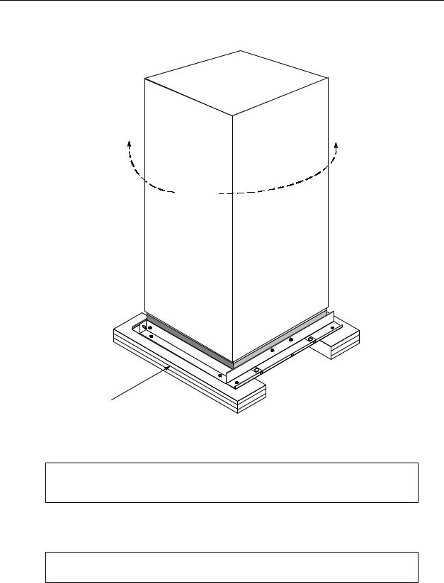
Unloading the Parallel Cabinet From the Pallet
The parallel cabinet consists of four supports secured to foam cushions. The foam cushions act as shock absorbers for the cabinet during shipment.
WARNING:
Cabinet is extremely heavy. If unloading instructions are not closely followed, the cabinet may tip and cause serious injury.
Turning the jacking bolts unevenly may cause the cabinet to become unbalanced. To prevent tipping, raise and lower the jacking bolts evenly. The cabinet should only be raised approximately 3 mm (1/8 in.) above the floor (just enough to remove foam cushions).
1.Remove the doors. Remove the retaining screw located inside each door at the bottom hinge pivot point, then lift the door off. Save the retaining screws for reinstallation of the doors.
2.Locate the field kit (packed inside of the cabinet or communication panel). Locate the four ½-in. jacking bolts and install them in the threaded holes in the front and rear supports. Place a floor protector underneath each jacking bolt, and screw the bolts down against them. The floor protectors will save the floor from being marred by the jacking bolts.
3.Loosen, but do not remove the hardware holding the foam cushions to the front and rear supports (labeled “1” in Figure 4).
4.Turn each jacking bolt consecutively, two full turns, until the foam cushions clear the floor by approximately 3 mm (1/8 in.).
5.After the foam cushions clear the floor, remove the hardware loosened in step 3. Pull the foam cushions out from under the cabinet, and discard or recycle them in a responsible manner.
Powerware 9315 Parallel Redundant System I & O |
11 |
164202013 Rev. D 041599 |
|
 Loading...