

Page 1

9
Uninterruptible Power
Supply
10 kVA -- 20 kVA
25 kVA -- 40 kVA
330
Installation and Operation
Manual
164201300 Rev. G
Page 2

------------------------------------------------------------------------
------------------------------------------------------------------------
----------------------------------
IMPORTANT SAFETY INSTRUCTIONS
Instructions Importantes Concernant La Sécurité
SAVE THESE INSTRUCTIONS
Conserver Ces Instructions
This manual contains important instructions for your Uninterruptible Power
Supply (UPS) system. You should follow these instructions during the
installation and maintenance of the UPS, options, accessories, and batteries.
Cette notice contient des instructions importantes
concernant la sécurité.
This equipment has been tested and found to comply with the limits for a Class A
digital device, pursuant to Part 15 of the FCC Rules. These limits are designed to
provide reasonable protection against harmful interference when the equipment is
operated in a commercial environment. This equipment generates, uses, and can
radiate radio frequency energy and, if not installed and used in accordance with
the instruction manual, may cause harmful interference to radio communications.
Operation of this equipment in a residential area is likely to cause harmful
interference in which case the user will be required to correct the interference at
their own expense.
ii
Powerware 9330 (10 kVA--40 kVA) Installation and Operation
164201300 REV. G 061502
Page 3

Tabl e of Content s
Introduction xiii...............................................
System Configurations xiv........................................
Using This Manual xv............................................
Conventions Used in This Manual xvi...............................
Safety Considerations xvii.........................................
Getting Help xvii..................................................
Section I Installation
1
Getting Started 1---1..........................................
1.1 Installing the UPS 1--- 1......................................
1.1.1 Creating an Installation Plan 1--- 1.............................
1.1.2 Preparing Your Site 1--- 1.....................................
1.1.3 Environment Considerations 1--- 2.............................
1.1.4 Preparing for Wiring the UPS System 1--- 2.....................
1.1.5 Inspecting and Unpacking Each Cabinet 1--- 3..................
2 Installing the UPS System 2---1................................
2.1 Preliminary Installation Information 2--- 1........................
2.2 UPS Cabinet Installation 2--- 2.................................
2.2.1 Unloading the Powerware 9330 (10 kVA---20 kVA)
UPS Cabinet from the Pallet 2--- 2.............................
2.2.2 Unloading the Powerware 9330 (25 kVA---40 kVA)
UPS Cabinet from the Pallet 2--- 5.............................
2.2.3 Installing Optional Remote Battery Power Wiring to the
Po w e r w a r e 9 33 0 ( 1 0 k V A --- 2 0 k V A ) U P S 2 --- 9...................
2.2.4 Installing Optional Remote Battery Power Wiring to the
Powerware 9330 (25 kVA--- 40 kVA) UPS 2--- 10...................
2.2.5 Installing UPS External Power Wiring 2--- 11......................
2.2.6 Installing Customer Connections 2--- 12.........................
2.2.7 Prepare for Installing Accessories 2--- 12........................
2.3 Battery Cabinet Installation 2---13..............................
2.3.1 Unloading the Battery Cabinet from the Pallet 2--- 13..............
2.3.2 Joining the Battery Cabinet to the UPS Cabinet 2--- 13............
2.3.3 Joining Additional Battery Cabinets 2--- 18.......................
2.4 Options Cabinet Installation 2--- 20..............................
2.4.1 Unloading the Options Cabinet from the Pallet 2--- 20.............
2.4.2 Joining the Options Cabinet to the UPS Cabinet 2--- 20............
2.4.3 Installing O ptions Cabinet Internal Power Wiring 2---26............
2.4.4 Installing Options Cabinet External Power Wiring 2---27...........
Powerware 9330 (10 kVA--40 kVA) Installation and Operation
164201300 REV. G 061502
iii
Page 4

2.5 Initial Startup 2---28...........................................
2.6 Completing the Installation Checklist 2---28......................
2.6.1 Installation Checklist 2--- 29....................................
3 Installing and Connecting Batte ries 3---1.......................
3.1 Important Safety Instructions 3---1............................
3.2 Battery Type 3---2...........................................
3.3 Battery Installation 3---2......................................
3.3.1 Installing Internal Batteries in the UPS Cabinet 3---2.............
3.3.2 Installing Internal Batteries in the Battery Cabinet 3---5...........
3.4 Connecting Batteries 3--- 5....................................
3.4.1 Electrically Connecting Integral Battery Strings 3--- 5.............
3.4.2 Electrically Connecting Battery Cabinet Battery Strings 3--- 6......
3.5 Installing and Connecting Remote Battery System 3---8..........
4 Installing a Remote Emergency Power Off (EPO) Control 4---1...
4.1 Installation Procedures 4---1..................................
4 . 2 To i n s t al l a R e m o te E P O : 4 --- 1................................
5 Installing a Remote Monitor Panel 5---1........................
5.1 Installation Procedures 5---1..................................
5 . 2 To i n s t al l a n R M P: 5 --- 2......................................
Section II Operation
6
Understanding UPS Operation 6---1............................
6.1 Looking Inside the UPS System 6--- 1..........................
6 . 2 U P S M od e s 6 --- 3............................................
6.2.1 Normal Mode 6 ---4..........................................
6.2.2 Bypass Mode 6---6..........................................
6.2.3 High Efficiency Mode 6--- 8...................................
6.2.4 Battery Mode 6--- 9..........................................
6.2.5 Test and Maintenance Bypass Modes 6--- 11.....................
6.3 Functional Description 6--- 12..................................
6.3.1 Input Rectifier 6--- 12..........................................
6.3.2 Boost Converter and Neutral Regulator 6--- 13....................
6.3.3 Inverter and Filter 6---13.......................................
6.3.4 Battery and Battery Charger 6---13.............................
6.3.5 Bypass 6--- 13................................................
6.3.6 Maintenance Bypass 6--- 13....................................
6.3.7 External Batteries 6---13.......................................
iv
Powerware 9330 (10 kVA--40 kVA) Installation and Operation
164201300 REV. G 061502
Page 5

7 Operational Controls and Features 7---1........................
7.1 General 7--- 1...............................................
7.2 UPS Operational Controls 7---1...............................
7.2.1 Control Panel 7 ---1..........................................
7.2.2 UPS Circuit Breakers 7---4...................................
7.2.3 Smart LOAD OFF 7---4.......................................
7.2.4 Maintenance Bypass Switch 7---4.............................
7.2.5 Cold Start Switch 7--- 4.......................................
7.3 UPS Standard Features 7--- 4.................................
7.3.1 Customer Interface 7--- 4.....................................
7.3.2 Advanced Battery Management 7--- 5..........................
7.3.3 High Efficiency Mode 7--- 5...................................
7.3.4 Customer Convenience Outlet 7--- 5...........................
7.3.5 Installation Features 7--- 5....................................
7.4 Options and Accessories 7--- 5................................
7.4.1 Remote EMERGENCY POWER OFF 7---5......................
7.4.2 Remote Monitor Panel 7 ---6..................................
7.4.3 Options Cabinet 7--- 6........................................
7.4.4 Battery Cabinets 7---6.......................................
7.4.5 Parallel Cabinet 7---6........................................
7.4.6 Communications 7--- 7.......................................
7.5 Safety Considerations 7---8...................................
7.6 Symbols, Controls, and Indicators 7---9........................
8 U s i n g t h e C o n t r o l P a n e l 8 --- 1..................................
8 . 1 D e sc r i pt i o n 8 --- 1............................................
8.2 Using the LCD Screen and Pushbuttons 8---2..................
8 . 3 U s in g t h e M ai n M e n u 8 --- 3...................................
8.3.1 Mimic Screen 8---3..........................................
8.3.2 System Event Screens 8---4..................................
8.3.3 System Meter Screens 8--- 5..................................
8.3.4 Setup Menu Screens 8---8...................................
8.4 System Controls Screen 8---12.................................
8.4.1 Charger Controls Screen 8--- 14................................
8.5 Unit Shutdown Screen 8---15..................................
8.6 Reading the Status Indicators 8---16............................
Powerware 9330 (10 kVA--40 kVA) Installation and Operation
164201300 REV. G 061502
v
Page 6

9 UPS Operating Instructions 9---1...............................
9 . 1 O pe r a t io n 9 --- 1.............................................
9.2 Starting the UPS in Normal Mode 9---1.........................
9 . 3 S t ar t i n g th e U P S i n B yp a s s M o de 9 --- 2........................
9.4 Starting the Power Processing Unit 9--- 3.......................
9 . 5 C o ld S t a r ti n g t h e U P S 9 --- 4...................................
9.6 Transfer from Normal to Bypass Mode 9--- 5....................
9.7 Transfer from Bypass to Normal Mode 9--- 6....................
9.8 T ransfer from Normal to High Efficiency Mode 9--- 6..............
9.9 T ransfer from High Efficiency to Normal Mode 9---6..............
9.10 T ransfer from Normal to Bypass Mode with UPS Shutdown 9--- 7..
9.11 UPS and Critical Load Shutdown 9---7.........................
9.12 UPS Maintenance Bypass Transfer 9 ---7.......................
9.13 Options Cabinet Maintenance Bypass Transfer 9---8.............
9.14 Using the Power Distribution Module 9--- 8......................
9.15 Using the LOAD OFF Pushbutton 9---8.........................
9.15.1 To Use the LOAD OFF Pushbutton 9---8........................
9.16 Using the REMOTE EMERGENCY POWER OFF Switch 9--- 9.....
9.16.1 T o Use the REPO Switch 9--- 9................................
10 U s i n g F e a t u r e s 1 0 --- 1.........................................
10.1 General 10--- 1...............................................
10.2 Building Alarm Monitoring 10--- 1...............................
10.3 General Purpose Relay Contacts 10--- 1.........................
10.4 Optional Remote Monitor Panel 10---2..........................
11 Responding to System Events 11---1...........................
11.1 General 11--- 1...............................................
11.2 System Event Horns 11---1....................................
11.3 System Event Lights 11---1....................................
11.4 System Event Messages 11---2................................
12 Communications 12---1.......................................
12.1 Description 12---1............................................
12.2 Communications and Expansion Ports 12--- 1....................
12.3 Connecting Equipment to a Serial Port 12---1....................
12.4 Configuring the Serial Ports 12--- 2..............................
12.5 Terminal Mode 12--- 3.........................................
12.5.1 Display UPS Control Panel 12--- 3..............................
12.5.2 Event History Log 12---12......................................
vi
Powerware 9330 (10 kVA--40 kVA) Installation and Operation
164201300 REV. G 061502
Page 7

13 Remote Notification 13---1....................................
13.1 Description 13---1............................................
13.2 Remote Notification Features 13--- 2............................
13.3 Description of Operation 13 ---3................................
13.3.1 Call Answer 13--- 3............................................
13.3.2 Call Out 13--- 3...............................................
13.3.3 Housekeeping 13---4.........................................
13.4 Hardware Requirements 13---5.................................
13.5 Configuring the Modem 13 ---6.................................
13.5.1 Basic Modem Configuration 13 ---6.............................
13.5.2 Configuring the Modem to Call a Remote Computer 13---6........
13.5.3 Configuring the Modem to Call a Numeric Pager 13--- 7...........
13.6 UPS Setup Configuration 13--- 8................................
13.6.1 Default Events 13---9.........................................
14 Maintaining the UPS System 14--- 1............................
14.1 General 14--- 1...............................................
14.2 Important Safety Instructions 14--- 1.............................
14.3 Performing Preventive Maintenance 14---3.......................
14.4 Maintenance Training 14---4...................................
15 Product Specifications 15---1..................................
15.1 Model Numbers 15---1........................................
15.2 UPS System Input 15--- 1......................................
15.3 UPS System Output 15--- 2....................................
15.4 Environmental Specifications 15--- 3............................
A p p e n d i x A --- C u s t o m e r I n f o r m a t i o n A --- 1.........................
Warranty W---1..................................................
Powerware 9330 (10 kVA--40 kVA) Installation and Operation
164201300 REV. G 061502
vii
Page 8

List of Figures
Figure 1---1. Powerware 9330 (10 kVA---20 kVA)
Cabinet as Shipped on Pallet 1--- 3...............................
Figure 1---2. Powerware 9330 (25 kVA---40 kVA)
Cabinet as Shipped on Pallet 1--- 4...............................
Figure 2---1. Removing Front Shipping Bracket
(Powerware 9330 (10 kVA--- 20 kVA)) 2---3.........................
Figure 2---2. Removing Rear Shipping Bracket
(Powerware 9330 (10 kVA--- 20 kVA)) 2---4.........................
Figure 2---3. Removing Front Shipping Bracket
(Powerware 9330 (25 kVA--- 40 kVA)) 2---6.........................
Figure 2---4. Removing Rear Shipping Bracket
(Powerware 9330 (25 kVA--- 40 kVA)) 2---7.........................
F ig u r e 2 --- 5 . B a t t er y C a b in e t I n s ta l l at i o n --- Po w e r w a r e 9 33 0 ( 1 0 k V A --- 2 0 k V A )
(Non–Permanent Mounting) 2---14.................................
F ig u r e 2 --- 6 . B a t t er y C a b in e t I n s ta l l at i o n --- Po w e r w a r e 9 33 0 ( 1 0 k V A --- 2 0 k V A )
(Permanent Mounting) 2--- 15.....................................
F ig u r e 2 --- 7 . B a t t er y C a b in e t I n s ta l l at i o n --- Po w e r w a r e 9 33 0 ( 2 5 k V A --- 4 0 k V A )
(Non–Permanent Mounting) 2---16.................................
F ig u r e 2 --- 8 . B a t t er y C a b in e t I n s ta l l at i o n --- Po w e r w a r e 9 33 0 ( 2 5 k V A --- 4 0 k V A )
(Permanent Mounting) 2--- 17.....................................
F ig u r e 2 --- 9 . O p t i o ns C a b i ne t I n s t a ll a t io n --- P o we r w ar e 9 3 30 (1 0 k VA --- 2 0 k V A)
(Non–Permanent Mounting) 2---21.................................
F ig u r e 2 --- 1 0. O pt i o n s C a bi n e t I ns t a l la t i o n --- Po w e rw a r e 9 3 3 0 ( 1 0 k VA --- 2 0 k V A)
(Permanent Mounting) 2--- 22.....................................
F ig u r e 2 --- 1 1. O pt i o n s C a bi n e t I ns t a l la t i o n --- Po w e rw a r e 9 3 3 0 ( 2 5 k VA --- 4 0 k V A)
(Non–Permanent Mounting) 2---23.................................
F ig u r e 2 --- 1 2. O pt i o n s C a bi n e t I ns t a l la t i o n --- Po w e rw a r e 9 3 3 0 ( 2 5 k VA --- 4 0 k V A)
(Permanent Mounting) 2--- 24.....................................
F ig u r e 3 --- 1 . B a t t er y S c h em a t i c --- P o w er w a re 9 3 3 0 (1 0 k V A --- 2 0 k V A) U P S
and Battery Cabinet 3---3........................................
F ig u r e 3 --- 2 . B a t t er y S c h em a t i c --- P o w er w a re 9 3 3 0 (2 5 k V A --- 4 0 k V A) U P S 3 --- 4...
Figure 3---3. Battery String Connection 3--- 5..................................
F ig u r e 4 --- 1 . R e m o t e EP O C o n t ro l 4 --- 1......................................
Figure 4---2. Remote EPO Control
(inside view of cover and bottom of enclosure) 4--- 2................
F ig u r e 5 --- 1 . R e m o t e Mo n i t o r P a n el ( R M P ) 5 --- 1...............................
Figure 5---2 Remote Monitor Card 5--- 3......................................
viii
F ig u r e 5 --- 3 . R e m o t e Mo n i t o r P a n el ( R M P ) --- To p I n t e rn a l V i ew 5 --- 3.............
Powerware 9330 (10 kVA--40 kVA) Installation and Operation
164201300 REV. G 061502
Page 9

F ig u r e 6 --- 1 . M a i n E le m e nt s o f t h e U P S S y st e m 6 --- 2...........................
Figure 6---2. Path of Current Through the UPS in Normal Mode 6--- 4.............
Figure 6---3. Path of Current Through the UPS in Bypass Mode 6---6.............
Figure 6---4. Path of Current Through the UPS in High Efficiency Mode 6 ---8......
Figure 6---5. Path of Current Through the UPS in Battery Mode 6---9.............
Figure 6---6. Path of Current Through the UPS in Test Mode 6--- 11................
Figure 6---7. Path of Current Through the UPS in
Maintenance Bypass Mode 6--- 12.................................
Figure 7---1. Powerware 9330 (10 kVA---20 kVA)
UPS Controls and Indicators 7 --- 2................................
Figure 7---2. Powerware 9330 (25 kVA---40 kVA)
UPS Controls and Indicators 7 --- 3................................
F ig u r e 8 --- 1 . U P S C o n t ro l P a n el 8 --- 1.........................................
F ig u r e 8 --- 2 . P a r ts of t h e L C D S c r ee n 8 --- 2....................................
F ig u r e 8 --- 3 . M i m ic S c r e en 8 --- 3.............................................
F ig u r e 8 --- 4 . E v e nt Hi s t o ry L o g S c r ee n 8 --- 4...................................
Figure 8---5. Active System Events Screen 8--- 4...............................
Figure 8---6. Input Meter Screen 8---5........................................
F ig u r e 8 --- 7 . O u t p ut Me t e r S c r e en 8 --- 5.......................................
F ig u r e 8 --- 8 . B y p as s M e t e r S c r e en 8 --- 6......................................
F ig u r e 8 --- 9 . B a t t er y M e t er S c r e en 8 --- 6......................................
F ig u r e 8 --- 1 0. O u tp u t C u rr e n t ( L o a d ) M e t e r S c r ee n 8 --- 7.........................
F ig u r e 8 --- 1 1. S e t u p M e nu Sc r e en 8 --- 8........................................
F ig u r e 8 --- 1 2. C o nt r a s t A d j u s t M e n u S c r e en 8 --- 8...............................
F ig u r e 8 --- 1 3. D a te & Ti me S c r e en 8 --- 9.......................................
F ig u r e 8 --- 1 4. Po r t S e t up S c r e e n 8 --- 1 0.........................................
F ig u r e 8 --- 1 5. Ve r s i o n s S c r e e n 8 --- 1 1...........................................
F ig u r e 8 --- 1 6. S ys t e m C o nt r o l s S c r e e n i n N or m a l M o d e 8 --- 1 2.....................
Figure 8--- 17. System Controls Screen in High Efficiency Mode 8 ---13..............
Figure 8---18. Charger Controls Screen 8 ---14...................................
F ig u r e 8 --- 1 9. S hu t d o wn S c r e en 8 --- 1 5.........................................
F ig u r e 1 0 --- 1 . R e m o t e M on i t o r Pa n e l 1 0 --- 2.....................................
Figure 12---1. Serial Port Pin Assignments 12--- 2.................................
F ig u r e 1 2 --- 2 . Ma i n S c re e n --- U P S N or m a l M im i c 1 2 --- 3..........................
F ig u r e 1 2 --- 3 . Ma i n S c re e n --- U P S O n B at t e r y M i m ic 1 2 --- 4.......................
F ig u r e 1 2 --- 4 . Ma i n S c re e n --- U P S O n B yp a s s M im i c 1 2 --- 4.......................
F ig u r e 1 2 --- 5 . Sy s t e m C o n t r ol s 1 2 --- 5..........................................
F ig u r e 1 2 --- 6 . Lo a d O f f 1 2 --- 5..................................................
F ig u r e 1 2 --- 7 . Ev e n ts --- H i s t o ry 1 2 --- 6..........................................
Powerware 9330 (10 kVA--40 kVA) Installation and Operation
164201300 REV. G 061502
ix
Page 10

F ig u r e 1 2 --- 8 . Ev e n ts --- A c t i ve 1 2 --- 6...........................................
F ig u r e 1 2 --- 9 . In p u t M et e r 1 2 --- 7...............................................
F ig u r e 1 2 --- 1 0 . Ou t p u t Me t e r 1 2 --- 7.............................................
F ig u r e 1 2 --- 1 1 . By p as s M e t e r 1 2 --- 8.............................................
F ig u r e 1 2 --- 1 2 . Ou t p u t Cu r r en t ( L o a d) M e t e r 12 --- 8................................
F ig u r e 1 2 --- 1 3 . Se t u p 1 2 --- 9....................................................
Figure 12---14. Contrast Adjust 12---9...........................................
Figure 12---15. Date and Time Setup 12 ---10......................................
Figure 12---16. Serial Port Setup 12--- 10..........................................
Figure 12---17. Versions 12--- 11..................................................
F ig u r e 1 2 --- 1 8 . Ev e n t Hi s t o ry L o g 12 --- 1 3.........................................
x
Powerware 9330 (10 kVA--40 kVA) Installation and Operation
164201300 REV. G 061502
Page 11

List of Tables
Ta b le 4 --- 1 . R em o t e E PO W ir e Te rm i n at i o n s 4 --- 3.................................
Ta b le 4 --- 2 . R em o t e E PO 4 --- 3.................................................
Ta b le 5 --- 1 . R M P W ir e Te rm i n at i o n s 5 --- 2.........................................
Ta b le 1 2 --- 1 . P i n A ss i g n me n t s f o r Se r i al P o r t ( DB --- 9 ) 1 2 --- 2.........................
Ta b le 1 2 --- 2 . S e r ia l C o m mu n i ca t i o n s P o r t 1 2 --- 2...................................
Powerware 9330 (10 kVA--40 kVA) Installation and Operation
164201300 REV. G 061502
xi
Page 12

This Page Intentionally Left Blank.
xii
Powerware 9330 (10 kVA--40 kVA) Installation and Operation
164201300 REV. G 061502
Page 13
Introduction
Powerware 9330 UPS true double conversion online power protection can be utilized
to prevent loss of valuable electronic information, minimize equipment downtime,
and/or minimize the adverse effect on equipment production due to unexpected power
problems.
The Powerware UPS System continually monitors incoming electrical power and
removes the surges, spikes, sags, and other irregularities that are inherent in
commercial utility power. Working with your building’s electrical system, the UPS
System supplies clean, consistent power that your sensitive electronic equipment
requires for reliable operation. During brownouts, blackouts, and other power
interruptions, internal and optional external battery strings provide emergency power to
safeguard your operation.
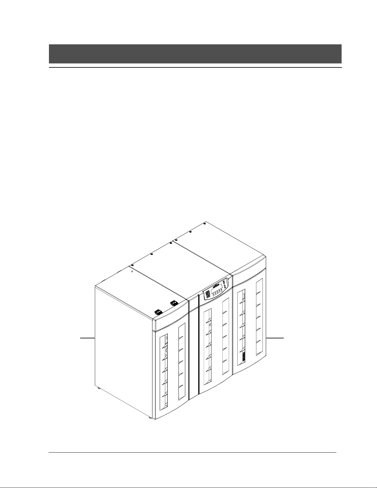
The UPS system is housed in free-standing cabinets. The cabinet sections line up and
match in style and color, and have safety shields behind the front panels for hazardous
voltage protection. The following illustrations depict a typical Powerware 9330 (10
kVA--- 20 kVA) UPS System and a typical Powerware 9330 (25 kVA---40 kVA) UPS
System
Typical Powerware 9330 (10 kVA--- 20 kVA) UPS System
Powerware 9330 (10 kVA--40 kVA) Installation and Operation
164201300 REV. G 061502
OPTIONS
CABINET
(OPTIONAL )
UPS
CABINET
BATTERY
CABINET
(OPTIONAL )
xiii
Page 14
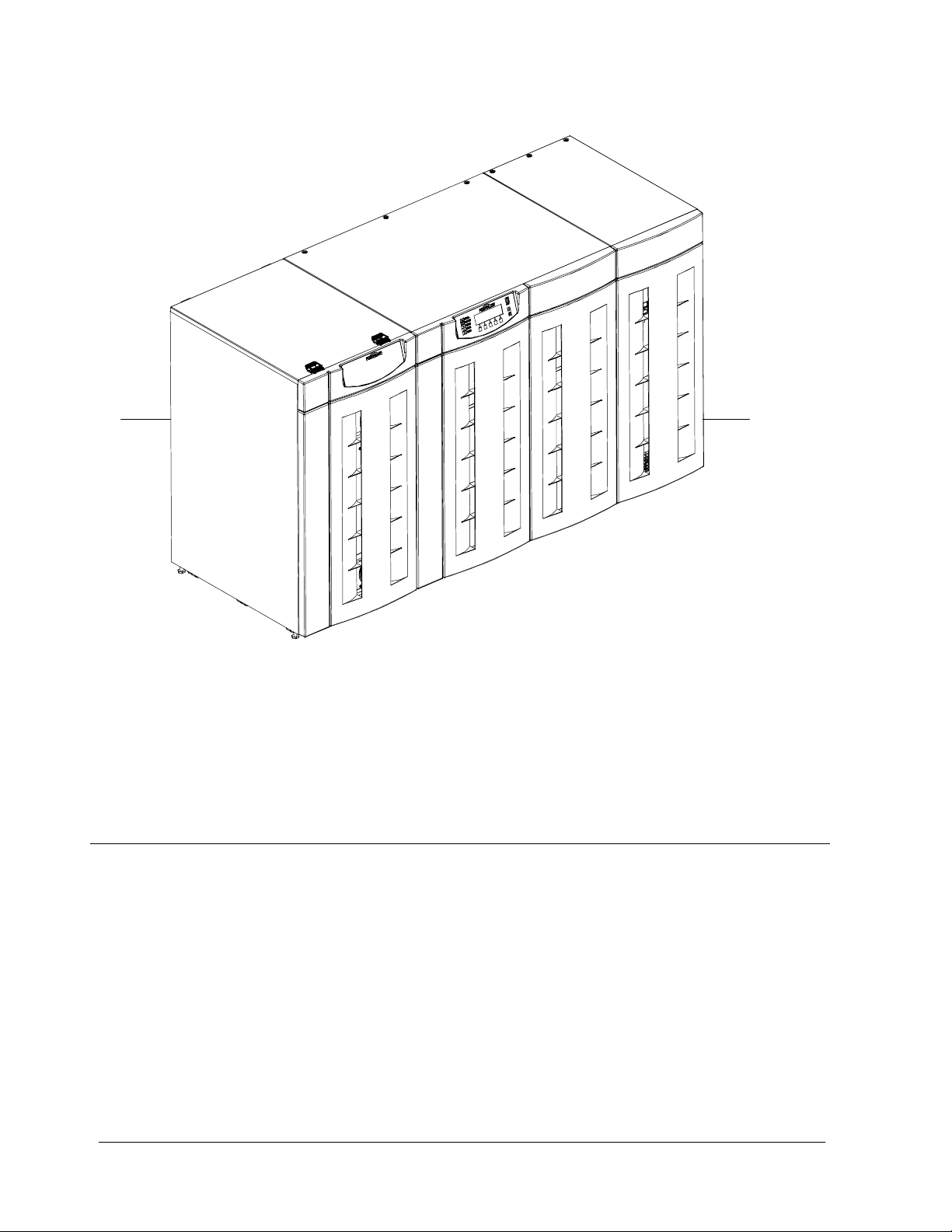
OPTIONS
CABINET
Typical Powerware 9330 (25 kVA--- 40 kVA) UPS System
System Configurations
These UPS system configurations are possible:
· Single Module UPS with integral battery
· Single Module UPS with integral battery and optional options cabinet
BATTERY
CABINET
UPS
CABINET
xiv
· Single Module UPS with integral battery and optional battery cabinet
· Single Module UPS with integral battery, optional battery cabinet, and optional
options cabinet
· Single Module UPS with remote battery
· Single Module UPS with remote battery and optional options cabinet
Powerware 9330 (10 kVA--40 kVA) Installation and Operation
164201300 REV. G 061502
Page 15

· Parallel System with one to four UPS modules with remote battery and optional
options cabinet
· Parall el System with one to four UPS modules and integral battery
· Parallel System with one to four UPS modules, integral battery, and optional
battery cabinet
· Parallel System with one to four UPS modules and remote battery
You can enhance any of these system configurations by adding an optional
accessories, such as a Remote Emergency Power Off (EPO) control, a Remote Monitor
Panel (RMP), and X ---Slot communications connectivity features.
Using This Manual
Your UPS functions automatically and requires very little attention during normal
operation. However, you should read and understand the procedures described in this
manual to ensure trouble-free operation. In particular, you should be thoroughly
familiar with the Remote Emergency Power Off procedure described in Chapter 9 of
this manual.
The information in this manual is divided into the sections and chapters listed.
The system you are installing dictates which parts of this manual you should read.
Everyone should read, at a minimum, the Introduction, Chapters 1, 2 , 8, and 9.
Introduction
The Introduction provides a brief description of the UPS system, a description of the
content of each chapter, safety, text conventions used in the manual and reference
information.
Section I
· Chapter 1 -- Getting Started -- tells you how to prepare your site for the
installation of your UPS system. It discusses equipment environmental
requirements, inspecting, and unpacking cabinets.
· Chapter 2 -- Installing the UPS System -- describes how to install the UPS
cabinets and optional equipment.
· Chapter 3 -- Installing Batteries -- provides battery safety, installation and
connection information.
· Chapter 4 -- Installing a Remote EPO Control -- contains information for
installing the optional Remote Emergency Power Off (EPO) control.
· Chapter 5 -- Installing a Remote Monitor Panel -- contains information for
installing the optional Remote Monitor Panel (RMP).
Section II
· Chapter 6 -- Understanding UPS Operation -- provides information on
understanding UPS operation.
· Chapter 7 -- Operational Controls and Features -- describes the standard
and optional operational features and controls of the UPS system.
Powerware 9330 (10 kVA--40 kVA) Installation and Operation
164201300 REV. G 061502
xv
Page 16

· Chapter 8 -- Using the Control Panel -- describes the controls and indicators
found on the Control Panel and shows the various information screens
displayed on the LCD screen.
· Chapter 9 -- UPS Operating Instructions -- contains startup and shutdown
procedures for the UPS system.
· Chapter 10 -- Using Features and Options -- contains descriptions and
instructions for the UPS system features and options.
· Chapter 11 -- Responding to System Events -- lists all the alarm messages
and notices that occur during operation of the UPS system.
· Chapter 12 -- Serial Communications -- describes the serial communications
features of the UPS system.
· Chapter 13 -- Remote Notification -- contains instructions for using the
remote notification feature of the UPS system.
· Chapter 14 -- Maintaining the UPS System -- contains maintenance
instructions for the UPS system.
· Chapter 15 -- Product Specifications -- provides detailed specifications for
the UPS system.
· Appendix A --Customer Information -- contains important information on
wiring requirements and recommendations, and important diagrams of the
cabinet’s mechanical details and electrical access.
· Warranty -- provides the Powerware warranty for this product.
Read through each procedure before you begin. Perform only those procedures
that apply to the UPS system you are installing or operating.
Conventions Used in This Manual
The text in this manual uses these conventions:
· Bold type highlights important concepts in discussions, key terms in
procedures, and menu options.
· Italic type highlights notes and new terms where they are defined.
· Rectangular boxes containing bold type are warnings or cautions that pertain to
the UPS system or its electrical connections.
In this manual, the term UPS refers only to the UPS cabinet and its internal elements.
The term UPS system refers to the entire power protection system—the UPS modules,
battery strings and options or accessories installed.
xvi
Powerware 9330 (10 kVA--40 kVA) Installation and Operation
164201300 REV. G 061502
Page 17

Safety Considerations
The UPS cabinet is designed for industrial or computer room applications, and contain
safety shields behind the doors. However, the UPS system is a sophisticated power
system and should be handled with appropriate care, following these guidelines:
· Keep surroundings clean and free from excess moisture.
· Do not operate the UPS system close to gas or electric heat sources.
· The system is not intended for outdoor use.
· The operating environment should be maintained within the parameters
stated in this manual.
· Keep the cabinet doors closed and locked to ensure proper cooling airflow
and to protect personnel from dangerous voltages inside the unit.
· The UPS system contains it s own power source. Lethal voltages are
present even when the UPS is disconnected from utility power.
WARNING:
Only AUTHORIZED SERVICE PERSONNEL should perform maintenance on or
service the UPS system.
If service or routine maintenance is required:
· Ensure all power is disconnected before performing installation or service.
· Ensure the area around the UPS system is clean and uncluttered.
· Battery maintenance or battery replacement should be performed only by
authorized service personnel.
· Observe all DANGER, CAUTION, and WARNING notices affixed to the
inside and outside of the equipment.
Powerware 9330 (10 kVA--40 kVA) Installation and Operation
164201300 REV. G 061502
xvii
Page 18

For More Information
This manual describes how to install and operate the UPS modules. For more
information about the installation and operation of a Parallel System, refer to the
following:
164201363 Powerware
Manual
The Installation section, provides installation instructions for the
Parallel cabinet. Site preparation, planning for installation, and
wiring and safety information are supplied. Detailed illustrations
of the cabinet, including dimensional and connection point
drawings are provided.
The Operation section, explains the functions of the Parallel
System; ; provides procedures for operating the Parallel System,
and information about maintenance and responding to system
events.
Contact your local Powerware Field Service office for information on how to obtain
copies of this manual.
9330 Parallel System Installation and Operation
Getting Help
If you need to schedule initial startup, need regional locations and telephone numbers,
have a question about any of the information in this manual, or have a question this
manual does not answer, please call Powerware Corporation at:
United States 1-800-843-9433
Canada 1-800-461-9166
Outside the U.S. Call your local representative
xviii
Powerware 9330 (10 kVA--40 kVA) Installation and Operation
164201300 REV. G 061502
Page 19

Section I
Installation
Powerware 9330 (10 kVA--40 kVA) Installation and Operation
164201300 REV. G 061502
Page 20

This Page Intentionally Left Blank.
Powerware 9330 (10 kVA--40 kVA) Installation and Operation
164201300 REV. G 061502
Page 21

n
Getting Started
1.1 Installing the UPS
The cabinet sections of the UPS are shipped on separate pallets. Use a forklift or
pallet jack, rated to handle the weight of the cabinets (refer to Drawing
164201300--- 3 in Appendix A for cabinet weights), to move the packaged cabinet
sections to the installation site, or as close as possible to the site, before unloading
from the pallet.
This is the basic sequence of the installation steps:
1. Create an installation plan for the UPS system (Chapter 1).
2. PrepareyoursitefortheUPSsystem(Chapter1).
3. Inspect, unpack, and unload the UPS cabinet sections (Chapter 1).
4. Wire the system (Chapter 2).
1
5. Install features, accessories, and/or options, as applicable (Chapter 3).
6. Complete the Installation Checklist (Chapter 2).
7. Have authorized service personnel perform preliminary operational checks and
startup.
NOTE: Startup and operational checks should be performed only by authorized
service personnel. This service is usually offered as part of the sales
contract for your UPS. Contact service in advance (usually a two week
notice is required) to reserve a preferred startup date.
1.1.1 Creating an Installation Plan
Before beginning to install the UPS system, read and understand how this manual
applies to the system being installed. Use the procedures and illustrations in the
following chapters to create a logical plan for installing the system.
1.1.2 Preparing Your Site
For your UPS system to operate at peak efficiency, your installation site should
meet the environmental parameters outlined in this manual. If you intend to
operate the system at an altitude higher than 1500 meters (5000 feet), contact your
local sales or service office for important information about high altitude operation.
The operating environment must meet the weight, airflow, size and clearance,
requirements specified in Appendix A.
Powerware 9330 (10 kVA--40 kVA) Installation and Operation
164201300 REV. G 061502
1--1
Page 22

The basic environmental requirements for operation of the UPS system are:
Ambient Temperature Range: 0 --- 4 0 ˚C (32--- 104˚F)
Recommended Operating Range: 20--- 25˚C (68 ---77˚F)
Maximum Relative Humidity: 95%, noncondensing
The UPS cabinets use forced air cooling to regulate internal component
temperature. Air inlets are in the front of the cabinet, and outlets are in the rear of
the cabinet. You must allow clearance in front of and behind each cabinet for
proper air circulation. Refer to Drawing 164201300---3 of Appendix A for clearance
requirements.
1.1.3 Environment Considerations
The life of the UPS system is adversely affected if the installation does not meet the
following guidelines:
1. The system must be installed on a level floor suitable for computer or
electronic equipment.
2. The system must be installed in a temperature-controlled indoor area free of
conductive contaminants.
Failure to follow guidelines may invalidate UPS warranty.
1.1.4 Preparing for Wiring the UPS System
For external wiring requirements, including the minimum AWG size of external
wiring, refer to Tables A through F in Appendix A for the Powerware 9330 (10
kVA---20 kVA) UPS or Tables G through M in Appendix A for the Powerware 9330
(25 kVA---40 kVA) UPS. The power wiring connections for this equipment are rated
at 90˚C. Control wiring for EPO and optional accessories (such as building alarms,
and monitoring interface) should be connected at the customer interface panels
and terminal blocks located inside the UPS using class 1 wiring methods.
1--2
Powerware 9330 (10 kVA--40 kVA) Installation and Operation
164201300 REV. G 061502
Page 23
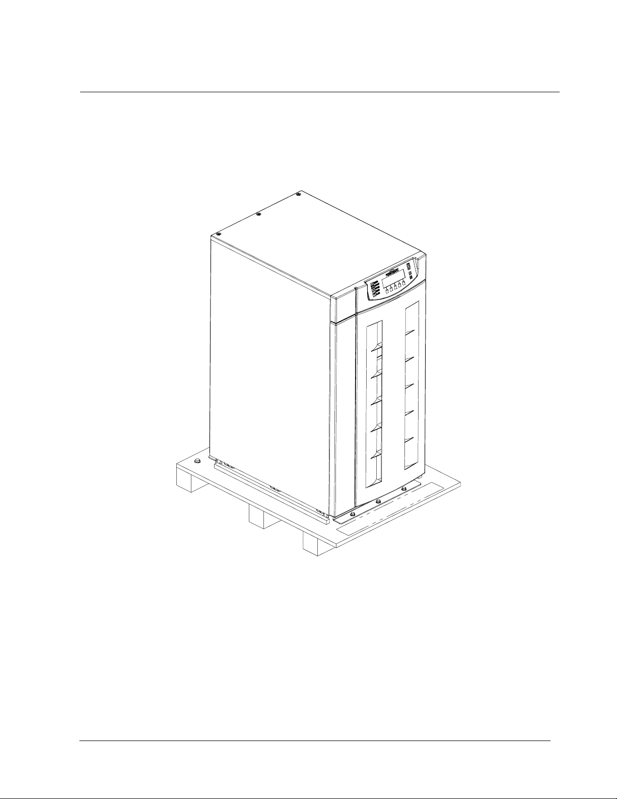
1.1.5 Inspecting and Unpacking Each Cabinet
The first task in preparing for installation is inspecting and unpacking the UPS
sections. The UPS and accessory cabinets are shipped bolted to wooden pallets,
a s s ho w n i n F i gu r e s 1 --- 1 o r 1 --- 2 , a nd pr o t ec t e d w i t h o u t er pr o t ec t i v e p a c k ag i n g
material.
Figure 1 ---1. Powerware 9330 (10 kVA ---20 kVA) UPS Cabinet as Shipped on Pallet
Powerware 9330 (10 kVA--40 kVA) Installation and Operation
164201300 REV. G 061502
1--3
Page 24
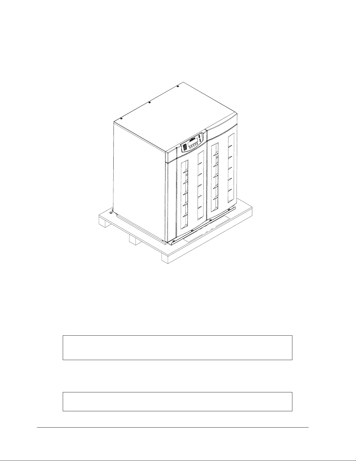
Figure 1 ---2. Powerware 9330 (25 kVA ---40 kVA) UPS Cabinet as Shipped on Pallet
1. Carefully inspect the outer packaging for evidence of damage during transit.
CAUTION:
Do not install a damaged cabinet. Report any damage to the carrier and
contact your local sales or service office immediately.
2. Use a forklift or other material handling equipment to move the cabinet to a
convenient unpacking area. Insert the forklift jacks between the pallet
supports on the bottom of the unit.
CAUTION:
Do not tilt cabinets more than 10 degrees from vertical.
1--4
Powerware 9330 (10 kVA--40 kVA) Installation and Operation
164201300 REV. G 061502
Page 25

3. Set each pallet on a firm, level surface, allowing a minimum clearance of
3 m (10 ft) on each side for removing the cabinets from the pallets.
4. Remove the protective covering from the cabinets.
5. Remove the packing material, and discard or recycle them in a responsible
manner.
6. After removing the protective covering, inspect the contents for any evidence
of physical damage, and compare each item with the Bill of Lading. If damage
has occurred or shortages are evident, contact the Powerware, Inc. Customer
Service Department immediately to determine the extent of the damage and its
impact upon further installation.
NOTE: While awaiting installation, protect the unpacked UPS cabinets from
moisture, dust, and other harmful contaminants. Failure to store and
protect the UPS properly may invalidate the warranty.
Powerware 9330 (10 kVA--40 kVA) Installation and Operation
164201300 REV. G 061502
1--5
Page 26

This Page Intentionally Left Blank.
1--6
Powerware 9330 (10 kVA--40 kVA) Installation and Operation
164201300 REV. G 061502
Page 27

Installing the UPS System
2.1 Preliminary Installation Information
WARNING:
Installation should be performed only by qualified personnel.
Refer to the following while installing the UPS system:
· Refer to Appendix A of this manual for installation drawings and additional
installation notes.
· Dimensions in this manual are in millimeters and inches.
· Do not tilt the cabinets more than 10˚ during installation.
· The conduit landing plates are to be removed to add conduit landing holes as
required. Plate material is 16 gauge steel (0.060 in. thick).
· The cabinets must be installed on a level floor suitable for computer or
electronic equipment.
2
· If perforated floor tiles are required for ventilation, place them in front of the
UPS. Refer to Table AA in Appendix A for equipment weight and point loading.
· Details about control wiring are provided in each procedure for connecting
options and features. Drawing 164201300 ---2 and Tables X and Y in Appendix A
identify the control wiring terminations.
Powerware 9330 (10 kVA--40 kVA) Installation and Operation
164201300 REV. G 061502
2--1
Page 28

2.2 UPS Cabinet Installation
To install an UPS cabinet, perform the procedures in the following paragraphs.
2.2.1 Unloading the Powerware 9330 (10 kVA ---20 kVA ) UPS
Cabinet from the Pallet
The UPS cabinet is bolted to a wooden pallet supported by wood skids. To
remove the pallet, perform the following procedure:
WARNING:
The UPS cabinet is heavy. Refer to Drawing 164201300--3 in Appendix A for
weight of cabinets. If unloading instructions are not closely followed, the
cabinet may cause serious injury.
CAUTION:
Do not tilt cabinets more than 10 degrees from vertical.
1. Use a forklift or other material handling equipment to move the cabinet to the
installation area. Insert the forklift jacks between the skids on the bottom of
the unit.
2. Remove left front solid panel, and right front vented panel from UPS cabinet.
Front panels are secured with magnetic latches and are removed by pulling
panels straight forward to disengage magnetic latches (see Figure 2---1).
3. If the leveling feet are not fully retracted, turn the leveling feet until they are
retracted.
4. Remove three bolts, (1) in Figure 2--- 2, securing the rear shipping bracket (3)
to the cabinet and three bolts (2) securing the bracket to the pallet. Remove
the rear shipping bracket. If installing cabinet permanently, retain shipping
brackets and securing hardware for later use.
5. Remove three bolts, (1) in Figure 2--- 1, securing front shipping bracket (3) to
the pallet. Do not remove bolts (2) securing the bracket to the cabinet.
6. Remove three bolts, (4) in Figure 2--- 2, securing removable skid (5) and
remove skid.
NOTE: In the following step the pallet will tilt and act as a ramp once the cabinet is
rolled beyond the the center of the pallet. Make sure to restrain the cabinet
as it continues to roll down the pallet/ramp. The front shipping bracket will
act as a brake to assist restraining the cabinet.
WARNING:
Do not stand directly behind the pallet while unloading the cabinet If
unloading instructions are not closely followed, the cabinet may cause
serious injury.
7. Slowly roll the cabinet toward the rear o f the pallet. Once the pallet tilts,
continue rolling the cabinet down the pallet until the cabinet is clear of the
pallet.
2--2
Powerware 9330 (10 kVA--40 kVA) Installation and Operation
164201300 REV. G 061502
Page 29
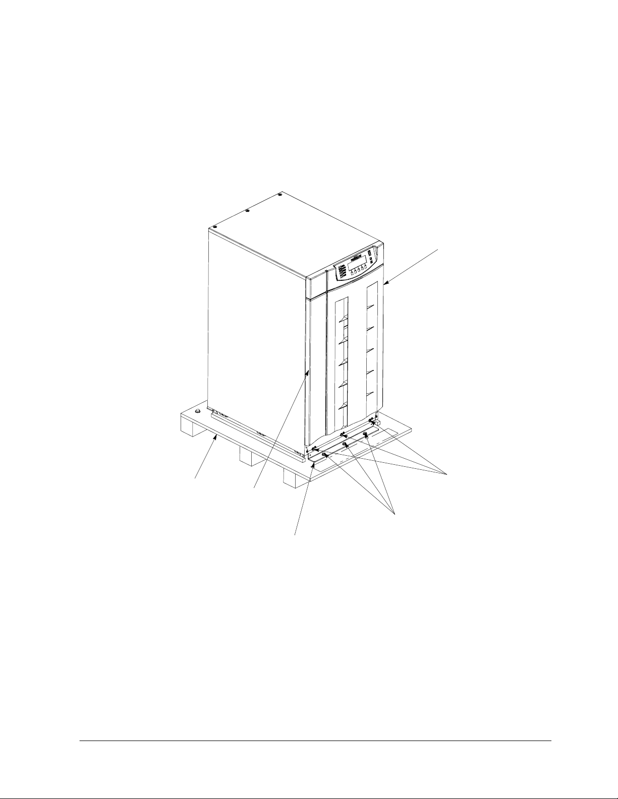
PALLET
VENTED
FRONT
PANE L
SHIPPING
BOLTS (2)
SOLID
FRONT
PANE L
SHIPPING
BOLTS (1)
FRONT
SHIPPING
BRACKET (3)
FRONT VIEW
Figure 2 ---1. Removing Front Shipping Bracket (Powerware 9330 (10 kVA --- 20 kVA))
Powerware 9330 (10 kVA--40 kVA) Installation and Operation
164201300 REV. G 061502
2--3
Page 30
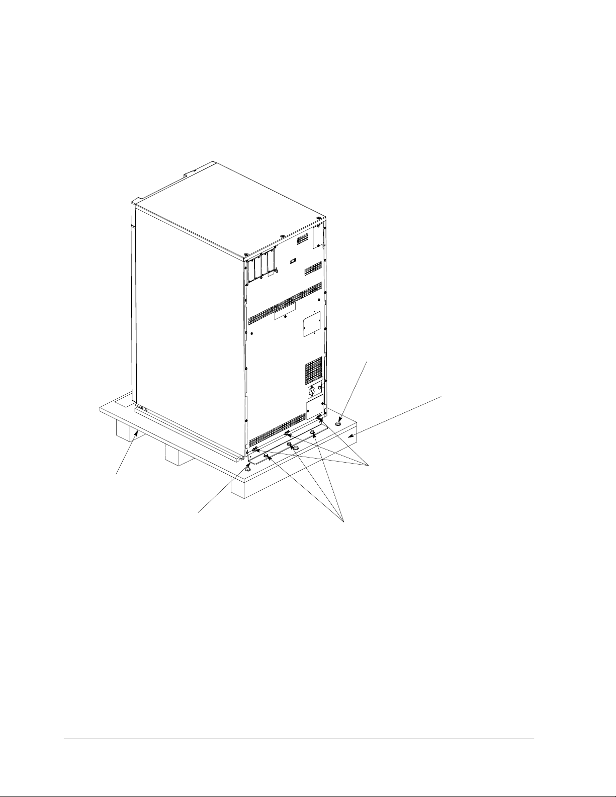
PALLET
REAR
SHIPPING
BRACKET (3)
SKID BOLTS (4)
(3 PLACES)
REMOVABLE
SKID (5)
SHIPPING
BOLTS (1)
SHIPPING
BOLTS (2)
REAR VIEW
Figure 2 ---2. Removing Rear Shipping Bracket (Powerware 9330 (10 kVA ---20 kVA))
2--4
Powerware 9330 (10 kVA--40 kVA) Installation and Operation
164201300 REV. G 061502
Page 31

8. Remove three bolts, (2) in Figure 2 ---1, securing front shipping bracket to the
cabinet.
9. If installing cabinet permanently, retain shipping brackets and hardware;
otherwise, discard or recycle the pallet and brackets in a responsible manner.
10. Roll cabinet to final installation location.
11. If permanently mounting the system, proceed to step 15; otherwise, proceed to
step 12.
12. If installing a Remote Battery System, proceed to paragraph 2.2.3; otherwise,
proceed to step 13.
13. Secure the UPS cabinet in position by lowering the leveling feet, until cabinet is
not resting on the casters and the cabinet is level.
14. If installing Battery and Options cabinets, repeat steps 1 through 10 for
remaining cabinets and proceed to paragraphs 2.3 and 2.4; otherwise,
proceed to paragraph 2.2.5.
15. If installing a Remote Battery System, proceed to paragraph 2.2.3; otherwise,
proceed to step 16.
16. Using retained hardware, reinstall shipping brackets previously removed to
front and rear of UPS cabinet with the angle facing outward.(see Figures 2---1
a nd 2 --- 2 ) .
17. If installing Battery and Options cabinets, repeat steps 1 through 10 for
remaining cabinets and proceed to paragraphs 2.3 and 2.4; otherwise,
proceed to step 18.
18. Secure cabinet to floor with contractor supplied hardware and proceed to
paragraph 2.2.5.
2.2.2 Unloading the Powerware 9330 (25 kVA ---40 kVA ) UPS
Cabinet from the Pallet
The UPS cabinet is bolted to a wooden pallet supported by wood skids. To
remove the pallet, perform the following procedure:
WARNING:
The UPS cabinet is heavy. Refer to Drawing 164201300--3 in Appendix A for
weight of cabinets. If unloading instructions are not closely followed, the
cabinet may cause serious injury.
CAUTION:
Do not tilt cabinets more than 10 degrees from vertical.
1. Use a forklift or other material handling equipment to move the cabinet to the
installation area. Insert the forklift jacks between the skids on the bottom of
the unit.
2. Remove left front solid panel, and front vented panels from UPS cabinet. Front
panels are secured with magnetic latches and are removed by pulling panels
straight forward to disengage magnetic latches (see Figure 2--- 3).
3. If the leveling feet are not fully retracted, turn the leveling feet until they are
retracted.
Powerware 9330 (10 kVA--40 kVA) Installation and Operation
164201300 REV. G 061502
2--5
Page 32

PALLET
VENTED
FRONT
PANE L S
SHIPPING
BOLTS (2)
SOLID
FRONT
PANE L
FRONT
SHIPPING
BRACKET (3)
SHIPPING
BOLTS (1)
FRONT VIEW
Figure 2 ---3. Removing Front Shipping Bracket (Powerware 9330 (25 kVA --- 40 kVA))
2--6
Powerware 9330 (10 kVA--40 kVA) Installation and Operation
164201300 REV. G 061502
Page 33

PALLET
SKID BOLTS (4)
(4 PLACES)
REMOVABLE
SKID(5)
SHIPPING
BOLTS (1)
REAR
SHIPPING
BRACKET (3)
SHIPPING
BOLTS (2)
REAR VIEW
Figure 2 ---4. Removing Rear Shipping Bracket (Powerware 9330 (25 kVA ---40 kVA))
Powerware 9330 (10 kVA--40 kVA) Installation and Operation
164201300 REV. G 061502
2--7
Page 34

4. Remove four bolts, (1) in Figure 2 ---4, securing the rear shipping bracket (3) to
the cabinet and four bolts (2) securing the bracket to the pallet. Remove the
rear shipping bracket. If installing cabinet permanently, retain shipping
brackets and securing hardware for later use.
5. Remove four bolts, (1) in Figure 2 ---3, securing front shipping bracket (3) to the
pallet. Do not remove bolts (2) securing the bracket to the cabinet.
6. Remove four bolts, (4) in Figure 2 ---4, securing removable skid (5) and
remove skid.
NOTE: In the following step the pallet will tilt and act as a ramp once the cabinet is
rolled beyond the the center of the pallet. Make sure to restrain the cabinet
as it continues to roll down the pallet/ramp. The front shipping bracket will
act as a brake to assist restraining the cabinet.
WARNING:
Do not stand directly behind the pallet while unloading the cabinet If
unloading instructions are not closely followed, the cabinet may cause
serious injury.
7. Slowly roll the cabinet toward the rear o f the pallet. Once the pallet tilts,
continue rolling the cabinet down the pallet until the cabinet is clear of the
pallet.
8. Remove four bolts, (2) in Figure 2 ---3, securing front shipping bracket to the
cabinet.
9. If installing cabinet permanently, retain shipping brackets and hardware;
otherwise, discard or recycle the pallet and brackets in a responsible manner.
10. Roll cabinet to final installation location.
11. If permanently mounting the system, proceed to step 15; otherwise, proceed to
step 12.
12. If installing a Remote Battery System, proceed to paragraph 2.2.4; otherwise,
proceed to step 13.
13. Secure the UPS cabinet in position by lowering the leveling feet, until cabinet is
not resting on the casters and the cabinet is level.
14. If installing Battery and Options cabinets, repeat steps 1 through 10 for
remaining cabinets and proceed to paragraphs 2.3 and 2.4; otherwise,
proceed to paragraph 2.2.5.
15. If installing a Remote Battery System, proceed to paragraph 2.2.4; otherwise,
proceed to step 16.
16. Using retained hardware, reinstall shipping brackets previously removed to
front and rear of UPS cabinet with the angle facing outward.(see Figures 2---3
a nd 2 --- 4 ) .
17. If installing Battery and Options cabinets, repeat steps 1 through 10 for
remaining cabinets and proceed to paragraphs 2.3 and 2.4; otherwise,
proceed to step 18.
2--8
18. Secure cabinet to floor with contractor supplied hardware and proceed to
paragraph 2.2.5.
Powerware 9330 (10 kVA--40 kVA) Installation and Operation
164201300 REV. G 061502
Page 35

2.2.3 Installing Optional Remote Battery Power Wiring to the
Powerware 9330 (10 kVA---20 kVA) UPS
If installing a remote battery system, perform the following procedure:
CAUTION:
When sizing battery system, do not exceed internal battery charger capabilities.
Refer to Chapter 15 “Specifications”, for maximum battery charger currents.
1. If not already removed, remove left front solid panel and right front vented
panel from the Powerware 9330 (10 kVA---20 kVA) UPS cabinet . Front panels
are secured with magnetic latches and are removed by pulling panels straight
forward to disengage magnetic latches (see Figure 2 ---1).
NOTE: Remove UPS cabinet input, output, and remote battery input conduit landing
plate to punch conduit holes.
2. Route battery cables to UPS remote battery terminal block. Refer to Appendix
A of this manual for wiring access information.
3. Connect positive, negative, and ground DC power wiring from external battery
source to the DC input and ground terminals in the UPS cabinet. Refer to
Appendix A of this manual for wiring and termination requirements and wiring
access information.
4. If permanently mounting the system, proceed to step 7; otherwise, proceed to
step 5.
5. Secure the UPS cabinet in position by lowering the leveling feet, until cabinet is
not resting on the casters and the cabinet is level.
6. If installing Battery and Options cabinets, repeat steps 1 through 10 in
paragraph 2.2.1 for Battery and Options cabinets and proceed to paragraphs
2.3 and 2.4; otherwise, proceed to paragraph 2.2.5.
7. Using retained hardware, reinstall shipping brackets previously removed to
front and rear of UPS cabinet with the angle facing outward.(see Figures 2---1
a nd 2 --- 2 ) .
8. If installing Battery and Options cabinets, repeat steps 1 through 10 in
paragraph 2.2.1 for Battery and Options cabinets and proceed to paragraphs
2.3 and 2.4; otherwise, proceed to step 9.
9. Secure cabinet to floor with contractor supplied hardware and proceed to
paragraph 2.2.5.
Powerware 9330 (10 kVA--40 kVA) Installation and Operation
164201300 REV. G 061502
2--9
Page 36

2.2.4 Installing Optional Remote Battery Power Wiring to the
Powerware 9330 (25 kVA---40 kVA) UPS
If installing a remote battery system, perform the following procedure:
CAUTION:
When sizing battery system, do not exceed internal battery charger capabilities.
Refer to Chapter 15 “Specifications”, for maximum battery charger currents.
1. If not already removed, remove left front solid panel, and front vented panels
from the Powerware 9330 (25 kVA--- 40 kVA) UPS cabinet . Front panels are
secured with magnetic latches and are removed by pulling panels straight
forward to disengage magnetic latches (see Figure 2 ---3).
NOTE: Remove UPS cabinet input, output, and remote battery input conduit landing
plate to punch conduit holes.
2. Route battery cables to UPS remote battery terminal block. Refer to Appendix
A of this manual for wiring access information.
3. Connect positive, negative, and ground DC power wiring from external battery
source to the DC input and ground terminals in the UPS cabinet. Refer to
Appendix A of this manual for wiring and termination requirements and wiring
access information.
4. If permanently mounting the system, proceed to step 7; otherwise, proceed to
step 5.
5. Secure the UPS cabinet in position by lowering the leveling feet, until cabinet is
not resting on the casters and the cabinet is level.
6. If installing Battery and Options cabinets, repeat steps 1 through 10 in
paragraph 2.2.2 for Battery and Options cabinets and proceed to paragraphs
2.3 and 2.4; otherwise, proceed to paragraph 2.2.5.
7. Using retained hardware, reinstall shipping brackets previously removed to
front and rear of UPS cabinet with the angle facing outward.(see Figures 2---3
a nd 2 --- 4 ) .
8. If installing Battery and Options cabinets, repeat steps 1 through 10 in
paragraph 2.2.2 for Battery and Options cabinets and proceed to paragraphs
2.3 and 2.4; otherwise, proceed to step 9.
9. Secure cabinet to floor with contractor supplied hardware and proceed to
paragraph 2.2.5.
2--10
Powerware 9330 (10 kVA--40 kVA) Installation and Operation
164201300 REV. G 061502
Page 37

2.2.5 Installing UPS External Power Wiring
1. Remove left front solid panel and right front vented panel from the Powerware
9330 (10 kVA---20 kVA) UPS cabinet or left front solid panel and front vented
panels from the Powerware 9330 (25 kVA---40 kVA) UPS cabinet. Front panels
are secured with magnetic latches and are removed by pulling panels straight
forward to disengage magnetic latches (see Figure 2 ---1 or 2 ---3).
2. Remove screws securing internal safety shield panels and remove panels to
gain access to input and output terminals.
NOTE: Remove UPS cabinet input and output conduit landing plate to punch
conduit holes.
3. Route input and output cables through wireway to UPS terminal blocks. Refer
to Appendix A of this manual for wiring access information.
4. If wiring a single feed system, proceed to step 5; if wiring a dual feed system,
proceed to step 7.
5. Connect phase A, B, C, and Neutral rectifier and bypass input power wiring
from source to the bypass input terminals in the UPS cabinet. Refer to
Appendix A of this manual for wiring and termination requirements and wiring
access information. Note wiring connections for single feed systems.
6. Proceed to step 10.
7. Disconnect single feed jumpers from phase A, B, and C terminals on Input
Breaker CB1 and Input Terminal strip TB2. Remove jumpers from cabinet.
8. Connect phase A, B, and C rectifier input power wiring from source to the
rectifier input terminals on Input Breaker CB1 in the UPS cabinet. Refer to
Appendix A of this manual for wiring and termination requirements and wiring
access information. Note wiring connections for dual feed systems.
9. Connect phase A, B, C, and Neutral bypass input power wiring from source to
the bypass input terminals on Input Terminal strip TB2 in the UPS cabinet.
Refer to Appendix A of this manual for wiring and termination requirements and
wiring access information. Note wiring connections for dual feed systems.
NOTE: If connecting the UPS to a Parallel Cabinet, refer to Powerware 9330 Parallel
Cabinet Installation and Operation manual referenced in the Introduction to
this manual.
10. Connect phase A, B, and C, and Neutral power wiring from output terminals to
the critical load. Refer to Appendix A of this manual for wiring and termination
requirements and wiring access information.
11. After wiring the UPS system to the facility power and critical load, be sure to
ground the system according to local and/or national electrical wiring codes.
12. When all wiring is complete, connect battery strings in accordance with
instructions contained in paragraph 3.4.1 of Chapter 3.
13. Secure the UPS by reinstalling safety shield panels, front vented panels, and
left front solid panel.
Powerware 9330 (10 kVA--40 kVA) Installation and Operation
164201300 REV. G 061502
2--11
Page 38

2.2.6 Installing Customer Co nnections
NOTE: If installing connections (building alarms, relay outputs, or external CAN for a
Parallel System) to the Communications Server Board (CSB), you must install
conduit between each device and the UPS cabinet for wiring these options.
Refer to Appendix A for the location of the interface points within the UPS
cabinet.
To prepare the UPS for wiring to Customer Connections:
1. Be sure the UPS system is turned off and all power sources are removed.
(See the operation section of this manual for shutdown instructions.)
2. Remove Customer Interface conduit landing plate from the UPS cabinet. Drill
or punch conduit holes for interface wiring.
3. To gain access to the Communications Server Board (CSB), remove top panel
from the UPS by removing screws at the back and front of the top panel.
4. Locate building alarm, relay, or CAN terminals on the CSB by referring to
drawings 164201300---2 and 164201300---8.
5. Refer to Appendix A of this manual for wiring and termination requirements.
6. Reinstall Customer Interface conduit landing plate.
7. Install conduit and wiring.
8. When wiring is complete, secure UPS by reinstalling all panels removed in
previous steps.
2.2.7 Prepare for Installing Accessories
NOTE: If installing accessories, such as the Remote Emergency Power Off
(REPO)switch, you must install conduit between the device and the UPS
cabinet for wiring the option.
To prepare the UPS for wiring to Accessories:
Be sure the UPS system is turned off and all power sources are removed.
1.
(See the operation section of this manual for shutdown instructions.)
2. If installing a Remote Monitor Panel (RMP), proceed to Chapter 5; otherwise
proceed to step 3.
3. Remove Customer Interface conduit landing plate from the UPS cabinet. Drill
or punch conduit holes for interface wiring.
4. To gain access to the Communications Server Board (CSB), remove top panel
from the UPS by removing screws at the back and front of the top panel.
5. Locate REPO terminals on the CSB by referring to drawings 164201300--- 2 and
164201300--- 8.
6. Reinstall Customer Interface conduit landing plate.
2--12
7. Refer to Chapter 4 for installation instructions.
8. When wiring is complete, secure UPS by reinstalling all panels removed in
previous steps.
Powerware 9330 (10 kVA--40 kVA) Installation and Operation
164201300 REV. G 061502
Page 39

2.3 Battery Cabinet Installation
To install optional battery cabinets, perform the procedures in the following
paragraphs.
2.3.1 Unloading the Battery Cabinet from the Pallet
To remove the Battery cabinet from the pallet, refer to paragraph 2.2.1.
2.3.2 Joining the Battery Cabinet to the UPS Cabinet
To join battery cabinets to the UPS, perform the following steps. Refer to
Figure 2---5 for non-permanent installation or Figure 2---6 for permanent installation
of the Powerware 9330 (10 kVA---20 kVA) UPS and Figure 2 ---7 for non-permanent
installation or Figure 2---8 for permanent installation of the Powerware 9330
( 25 k V A --- 4 0 k V A) U P S .
1. Roll the Battery cabinet to a spot near the right side of the UPS.
2. Remove left front solid panel, and right front vented panel from the Powerware
9330 (10 kVA---20 kVA) UPS cabinet or left front solid panel and front vented
panels from Powerware 9330 (25 kVA---40 kVA) UPS cabinet. Front panels are
secured with magnetic latches and are removed by pulling panels straight
forward to disengage magnetic latches (see Figure 2 ---1 or 2 ---3).
3. Remove front vented panel from Battery cabinet. The front panel is secured
with magnetic latches and are removed by pulling panels straight forward to
disengage magnetic latches.
4. Remove right side outside panel from UPS cabinet. Retain hardware.
5. Remove right side panel from Battery cabinet. Retain hardware.
6. Install side panel removed from the Battery cabinet to the right side of the UPS
cabinet. Secure with screws removed from UPS cabinet.
7. Find the battery cable with 2-pole connector in the Battery cabinet. Route this
connector into the UPS cabinet and mate with the matching connector in the
U P S (s e e F i g ur e s 2 --- 5 , 2 --- 6 , 2 --- 7 , o r 2 --- 8 ).
8. Push the Battery cabinet against the right side of the U PS cabinet.
9. If permanently mounting the system, proceed to step 16; otherwise, proceed to
step 10.
10. Secure the Battery cabinet in position by lowering the leveling feet, until
cabinet is not resting on the casters and the cabinet is level.
11. Secure the front of Battery cabinet to the front of the UPS cabinet by sliding the
angle grounding/mounting bracket, from installation kit, behind the base of the
Battery and UPS cabinets with the bottom angle facing outward (see Figures
2--- 5 or 2 ---7). Use hardware provided in the kit to secure the bracket.
12. Remove the top side panel mounting screw (tie/grounding bracket location in
Figures 2---5 o r 2 ---7) from both the Battery and UPS cabinets.
13. Secure the back of Battery cabinet to the back of the UPS cabinet with the
tie/grounding bracket. Secure the bracket with the side panel mounting
screws.
Powerware 9330 (10 kVA--40 kVA) Installation and Operation
164201300 REV. G 061502
2--13
Page 40

BATTERY
CONNECTOR
Figure 2 ---5. Battery Cabinet Installation --- Powerware 9330 (10 kVA ---20 kVA)
(Non–Permanent Mounting)
2--14
Powerware 9330 (10 kVA--40 kVA) Installation and Operation
164201300 REV. G 061502
Page 41

BATTERY
CONNECTOR
Figure 2 ---6. Battery Cabinet Installation --- Powerware 9330 (10 kVA ---20 kVA)
(Permanent Mounting)
Powerware 9330 (10 kVA--40 kVA) Installation and Operation
164201300 REV. G 061502
2--15
Page 42

BATTERY
CONNECTOR
Figure 2 ---7. Battery Cabinet Installation --- Powerware 9330 (25 kVA ---40 kVA)
(Non–Permanent Mounting)
2--16
Powerware 9330 (10 kVA--40 kVA) Installation and Operation
164201300 REV. G 061502
Page 43

BATTERY
CONNECTOR
Figure 2 ---8. Battery Cabinet Installation --- Powerware 9330 (25 kVA ---40 kVA)
(Permanent Mounting)
Powerware 9330 (10 kVA--40 kVA) Installation and Operation
164201300 REV. G 061502
2--17
Page 44

14. Install side panel removed from the UPS cabinet to the right side of the Battery
cabinet. Secure with screws removed from Battery cabinet.
15. When all wiring is complete, proceed to Chapter 3 and connect battery strings
in accordance with instructions contained in paragraph 3.4.2.
16. Using retained hardware, reinstall shipping brackets previously removed, to
front and rear of Battery cabinet with the angle facing outward.(see
F ig u r es 2 --- 6 o r 2 --- 8 ) .
17. Secure the front of Battery cabinet to the front of the UPS cabinet with the long
flat grounding/mounting bracket from the installation kit (see Figures 2 ---6 or
2--- 8). Use hardware provided in the kit to secure the bracket.
18. Remove the top side panel mounting screw (tie/grounding bracket location in
Figure 2---6) from both the Battery and UPS cabinets.
19. Secure the back of Battery cabinet to the back of the UPS cabinet with the
tie/grounding bracket. Secure the bracket with the side panel mounting
screws.
20. Install side panel removed from the UPS cabinet to the right side of the Battery
cabinet. Secure with screws removed from Battery cabinet.
21. Secure cabinets to floor with contractor supplied hardware.
22. When all wiring is complete, proceed to Chapter 3 and connect battery strings
in accordance with instructions contained in paragraph 3.4.2.
2.3.3 Joining Additional Battery Cabinets
To join additional battery cabinets, perform the following steps. R efer to
Figure 2---5 for non-permanent installation or Figure 2---6 for permanent installation
of the Powerware 9330 (10 kVA---20 kVA) UPS and Figure 2 ---7 for non-permanent
installation or Figure 2---8 for permanent installation of the Powerware 9330
( 2 5 k V A --- 4 0 k V A) U P S .
1. Roll the Battery cabinet to a spot near the right side of the previously installed
Battery cabinet.
2. Remove front vented panels from the Battery cabinets. The front panels are
secured with magnetic latches and are removed by pulling panels straight
forward to disengage magnetic latches (see Figure 2 ---1).
3. Remove right side outside panel from previously installed Battery cabinet.
Retain hardware.
4. Remove right side panel from new Battery cabinet. Retain hardware.
5. Install side panel removed from the new Battery cabinet to the right side of the
previously installed Battery cabinet. Secure with screws removed from Battery
cabinet.
6. Find the battery cable with 2-pole connector in the new Battery cabinet. Route
this connector into the previously installed Battery cabinet and mate with the
m a t c h i n g c o n n ec t o r i n t h e c a b in e t ( s ee F i g u re s 2 --- 5 , 2 --- 6 , 2 --- 7 , o r 2 --- 8 ) .
2--18
7. Push the new Battery cabinet against the right side of the previously installed
Battery cabinet.
Powerware 9330 (10 kVA--40 kVA) Installation and Operation
164201300 REV. G 061502
Page 45

8. If permanently mounting the system, proceed to step 15; otherwise, proceed to
step 9.
9. Secure the new Battery cabinet in position by lowering the leveling feet, until
cabinet is not resting on the casters and the cabinet is level.
10. Secure the front of Battery cabinets by sliding the angle grounding/mounting
bracket, from installation kit, behind the base of the Battery cabinets with the
bottom angle facing outward (see Figures 2 ---5 or 2 ---7). Use hardware
provided in the kit to secure the bracket.
11. Remove the top side panel mounting screw (tie/grounding bracket location in
Figures 2---5 or 2 ---7) from both the Battery cabinets.
12. Secure the back of Battery cabinets with the tie/grounding bracket. Secure the
bracket with the side panel mounting screws.
13. Install side panel removed from the previously installed Battery cabinet to the
right side of the new Battery cabinet. Secure with screws removed from
Battery cabinet.
14. When all wiring is complete, proceed to Chapter 3 and connect battery strings
in accordance with instructions contained in paragraph 3.4.2.
15. Using retained hardware, reinstall shipping brackets previously removed to
front and rear of new Battery cabinet with the angle facing outward.(see
F ig u r es 2 --- 6 o r 2 --- 8 ) .
16. Secure the front of Battery cabinets with the long flat grounding/mounting
b ra c k e t f r o m t h e in s t a ll a t io n k i t ( s e e Fi g u re s 2 --- 6 o r 2 --- 8 ) . U s e h a r d w a r e
provided in the kit to secure the bracket.
17. Remove the top side panel mounting screw (tie/grounding bracket location in
Figures 2---6 or 2 ---8) from both the Battery cabinets.
18. Secure the back of Battery cabinets with the tie/grounding bracket. Secure the
bracket with the side panel mounting screws.
19. Install side panel removed from the previously installed Battery cabinet to the
right side of the new Battery cabinet. Secure with screws removed from
Battery cabinet.
20. Secure cabinets to floor with contractor supplied hardware.
21. When all wiring is complete, proceed to Chapter 3 and connect battery strings
in accordance with instructions contained in paragraph 3.4.2.
22. Repeat steps 1 through 21 to join additional Battery cabinets.
Powerware 9330 (10 kVA--40 kVA) Installation and Operation
164201300 REV. G 061502
2--19
Page 46

2.4 Options Cabinet Installation
2.4.1 Unloading the Options Cabinet from the Pallet
To remove the Options cabinet from the pallet, refer to paragraph 2.2.1.
2.4.2 Joining the Options Cabinet to the UPS Cabinet
To join the Options cabinets to the UPS, perform the following steps. Refer to
Figure 2---9 for non-permanent installation or Figure 2---10 for permanent
installation of the Powerware 9330 (10 kVA---20 kVA) UPS and Figure 2---11 for
non-permanent installation or Figure 2 ---12 for permanent installation of the
Powerware 9330 (25 kVA--- 40 kVA) UPS.
NOTE: The cables used in step 8 are coiled outside the Options cabinet and are
attached at the factory to the input and output terminals of the Options
cabinet.
1. Roll the Options cabinet to a spot near the left side of the UPS.
2. Remove left front solid panel, and right front vented panel from the Powerware
9330 (10 kVA---20 kVA) UPS cabinet or left front solid panel and front vented
panels from Powerware 9330 (25 kVA---40 kVA) UPS cabinet. Front panels are
secured with magnetic latches and are removed by pulling panels straight
forward to disengage magnetic latches (see Figure 2 ---1 or 2 ---3).
3. Remove screws securing UPS cabinet internal safety shield panel and remove
panel to gain access to wireway.
4. Remove front vented panel from Options cabinet. The front panel is secured
with magnetic latches and are removed by pulling panels straight forward to
disengage magnetic latches.
5. Remove left side outside panel from UPS cabinet. Retain hardware.
6. Remove left side panel from Options cabinet. Retain hardware.
7. Install side panel removed from the Options cabinet to the left side of the UPS
cabinet. Secure with screws removed from UPS cabinet.
8. Route the input and output cables from the Options cabinet through cutout in
UPS cabinet side to the UPS wireway.
9. Push the Options cabinet against the left side of the UPS cabinet.
10. If permanently mounting the system, proceed to step 16; otherwise, proceed to
step 11.
11. Secure the Options cabinet in position by lowering the leveling feet, until
cabinet is not resting on the casters and the cabinet is level.
12. Secure the front of Options cabinet to the front of the UPS cabinet by sliding
the angle grounding/mounting bracket, from installation kit, behind the base of
the O ptions and UPS cabinets with the bottom angle facing outward (see
Figure 2---9 or 2---11). Use hardware provided in the kit to secure the bracket.
2--20
Powerware 9330 (10 kVA--40 kVA) Installation and Operation
164201300 REV. G 061502
Page 47

Figure 2 ---9. Options Cabinet Installation --- Powerware 9330 (10 kVA ---20 kVA)
(Non–Permanent Mounting)
Powerware 9330 (10 kVA--40 kVA) Installation and Operation
164201300 REV. G 061502
2--21
Page 48

Figure 2 ---10. Options Cabinet Installation --- Powerware 9330 (10 kVA ---20 kVA)
(Permanent Mounting)
2--22
Powerware 9330 (10 kVA--40 kVA) Installation and Operation
164201300 REV. G 061502
Page 49

Figure 2 ---11. Options Cabinet Installation --- Powerware 9330 (25 kVA ---40 kVA)
(Non–Permanent Mounting)
Powerware 9330 (10 kVA--40 kVA) Installation and Operation
164201300 REV. G 061502
2--23
Page 50

Figure 2 ---12. Options Cabinet Installation --- Powerware 9330 (25 kVA ---40 kVA)
(Permanent Mounting)
2--24
Powerware 9330 (10 kVA--40 kVA) Installation and Operation
164201300 REV. G 061502
Page 51

13. Remove the top side panel mounting screw (tie/grounding bracket location in
F ig u r es 2 --- 9 o r 2 --- 1 1 ) f ro m b o t h t he Op t i o n a n d U P S c a bi n e ts .
14. Secure the back of Options cabinet to the back of the UPS cabinet with the
tie/grounding bracket. Secure the bracket with the side panel mounting
screws.
15. Proceed to paragraph 2.4.3.
16. Using retained hardware, reinstall shipping brackets previously removed to
front and rear of Options cabinet with the angle facing outward.(see Figures
2 --- 1 0 o r 2 --- 1 2 ) .
17. Secure the front of Options cabinet to the front of the UPS cabinet with the
long flat grounding/mounting bracket from the installation kit (see Figures
2--- 10). Use hardware provided in the kit to secure the bracket.
18. Remove the top side panel mounting screw (tie/grounding bracket location in
F ig u r e 2 --- 1 0 o r 2 --- 1 2 ) f ro m b o t h t h e Op t i o n a n d U P S c a bi n e t s.
19. Secure the back of Options cabinet to the back of the UPS cabinet with the
tie/grounding bracket. Secure the bracket with the side panel mounting
screws.
20. Secure cabinets to floor with contractor supplied hardware.
21. Proceed to paragraph 2.4.3.
Powerware 9330 (10 kVA--40 kVA) Installation and Operation
164201300 REV. G 061502
2--25
Page 52

2.4.3 Installing Options Cabinet Internal Power Wiring
1. Remove left front solid panel, and right front vented panel from the Powerware
9330 (10 kVA---20 kVA) UPS cabinet or left front solid panel and front vented
panels from Powerware 9330 (25 kVA---40 kVA) UPS cabinet. Front panels are
secured with magnetic latches and are removed by pulling panels straight
forward to disengage magnetic latches (see Figure 2 ---1).
2. Remove screws securing UPS internal safety shield panel and remove panel to
gain access to input and output terminals.
3. Route input and output cables from Options cabinet through wireway to UPS
terminal blocks. Refer to Appendix A of this manual for wiring access
information.
4. If wiring a single feed system, proceed to step 5; if wiring a dual feed system,
proceed to step 7.
5. Connect phase A, B, C, and Neutral rectifier and bypass input power wiring
from the Options cabinet to the bypass input terminals in the UPS cabinet.
Refer to Appendix A of this manual for wiring and termination requirements and
wiring access information. Note wiring connections for single feed systems.
6. Proceed to step 10.
7. Disconnect single feed jumpers from phase A, B, and C terminals on Input
Breaker CB1 and Input Terminal strip TB2 in UPS cabinet. Remove jumpers
from cabinet.
8. Connect phase A, B, and C mains input power wiring from Options cabinet to
the rectifier input terminals on Input Breaker CB1 in the UPS cabinet. Refer to
Appendix A of this manual for wiring and termination requirements and wiring
access information. Note wiring connections for dual feed systems.
9. Connect phase A, B, C, and Neutral bypass input power wiring from Options
cabinet to the bypass input terminals on Input Terminal strip TB2 in the UPS
cabinet. Refer to Appendix A of this manual for wiring and termination
requirements and wiring access information. Note wiring connections for dual
feed systems.
10. Connect phase A, B, and C and Neutral output power wiring from the Options
cabinet to the output terminals in the UPS cabinet. Refer to Appendix A of this
manual for termination requirements and wiring access information.
11. Secure the UPS by reinstalling safety shield panels, front vented panels, and
front solid panel.
2--26
Powerware 9330 (10 kVA--40 kVA) Installation and Operation
164201300 REV. G 061502
Page 53

2.4.4 Installing Options Cabinet External Power Wiring
NOTE: Remove Options cabinet input and output conduit landing plate to punch
conduit holes.
1. Route input and output cables to input/output terminal block. Refer to
Appendix A of this manual for wiring access information.
2. If optional Power Distribution Module (PDM) is installed in the Options cabinet,
proceed to step 10; otherwise, proceed to step 3.
3. If wiring a single feed system, proceed to step 4; if wiring a dual feed system,
proceed to step 6.
4. Connect phase A, B, C, and Neutral mains and bypass input power wiring from
source to the bypass input terminals in the Options cabinet. Refer to Appendix
A of this manual for wiring and termination requirements and wiring access
information. Note wiring connections for single feed systems.
5. Proceed to step 8.
6. Connect phase A, B, and C mains input power wiring from source to the mains
input terminals in the Options cabinet. Refer to Appendix A of this manual for
wiring and termination requirements and wiring access information. Note
wiring connections for dual feed systems.
7. Connect phase A, B, C, and Neutral bypass input power wiring from source to
the bypass input terminals in the Options cabinet. Refer to Appendix A of this
manual for wiring and termination requirements and wiring access information.
Note wiring connections for dual feed systems.
8. Connect phase A, B, and C and Neutral output power wiring from output
terminals to critical load. Refer to Appendix A of this manual for wiring and
termination requirements and wiring access information.
9. Proceed to step 17.
10. If wiring a single feed system, proceed to step 11; if wiring a dual feed system,
proceed to step 13.
11. Connect phase A, B, C, and Neutral mains and bypass input power wiring from
source to the bypass input terminals in the Options cabinet. Refer to Appendix
A of this manual for wiring and termination requirements and wiring access
information. Note wiring connections for single feed systems.
12. Proceed to step 15.
13. Connect phase A, B, and C mains input power wiring from source to the mains
input terminals in the Options cabinet. Refer to Appendix A of this manual for
wiring and termination requirements and wiring access information. Note
wiring connections for dual feed systems.
14. Connect phase A, B, C, and Neutral bypass input power wiring from source to
the bypass input terminals in the Options cabinet. Refer to Appendix A of this
manual for wiring and termination requirements and wiring access information.
Note wiring connections for dual feed systems.
Powerware 9330 (10 kVA--40 kVA) Installation and Operation
164201300 REV. G 061502
2--27
Page 54

NOTE: Remove Options cabinet PDM conduit landing plate to punch conduit holes.
15. Install Square-D Type QO or QOB breakers into PDM panelboard. Refer to
Appendix A of this manual for access information.
16. Wire branch circuits in accordance with branch circuit breaker manufacturers
instructions (output from the UPS or Options cabinet is prewired to the PDM).
Refer to Appendix A of this manual wiring access information.
17. After wiring the Options cabinet to the facility power and critical load, be sure
to ground the system according to local and/or national electrical wiring codes.
18. When all wiring is complete, connect battery strings in accordance with
instructions contained in paragraphs 3.4.1 and 3.4.2 of Chapter 3.
19. Secure the UPS by reinstalling safety shield panels, front vented panels, and
front solid panel.
20. Install side panel removed from the UPS cabinet to the left side of the Options
cabinet.
21. Secure the Options cabinet by reinstalling front vented panel.
2.5 Initial Startup
Startup and operational checks should be performed only by authorized service
personnel. Contact service in advance (usually a two week notice is required) to
reserve a preferred startup date.
2.6 Completing the Installation Checklist
The final step in installing your UPS system is completing the following Installation
Checklist. This checklist ensures that you have completely installed all hardware,
cables, and other equipment. Completing all items listed on the checklist will
ensure a smooth installation. You should make a copy of the Installation Checklist
before filling it out, and retain the original.
After your installation is complete, a service representative will be able to verify the
operation of your UPS system and commission it to support your critical load. The
service representative cannot perform any installation tasks other than verifying
software and operating setup parameters. Service personnel may request a copy
of the completed Installation Checklist to be sure you have completed all
applicable equipment installation.
NOTE: The Installation Checklist MUST be completed prior to starting the UPS
system for the first time.
2--28
Powerware 9330 (10 kVA--40 kVA) Installation and Operation
164201300 REV. G 061502
Page 55

2.6.1 Installation Checklist
-All packing materials and restraints have been removed from each cabinet.
-Each cabinet in the UPS system is placed in its installed location.
-A cabinet grounding/mounting kit is installed between any cabinets that are bolted
together.
-All conduits, and cables are properly routed to the UPS and auxiliary cabinets.
-All power cables are properly sized and terminated.
-The bypass source of the supply is a four wire wye configuration. If using dual feed, the
rectifier source is a three wire connection from a wye configuration.
-All telephone and network connections have been completed.
-A ground conductor is properly installed.
-Internal battery cabinet connections have been completed (plugs, etc.).
-Air conditioning equipment is installed and operating correctly.
-The area around the installed UPS system is clean and dust-free. (It is recommended
that the UPS be installed on a level floor suitable for computer or electronic
equipment.)
-Adequate workspace exists around the UPS and other cabinets.
-Adequate lighting is provided around all UPS equipment.
-A 120V service outlet is located within 25 feet of the UPS equipment.
-The Remote Emergency Power Off (EPO) device is mounted in its installed location
and its wiring terminated inside the UPS cabinet.
-Summary alarms and/or building alarms are wired appropriately. (OPTIONAL)
-Startup and operational checks performed by authorized service personnel.
Powerware 9330 (10 kVA--40 kVA) Installation and Operation
164201300 REV. G 061502
2--29
Page 56

Notes
________________________________________________________________________________
________________________________________________________________________________
________________________________________________________________________________
________________________________________________________________________________
________________________________________________________________________________
________________________________________________________________________________
________________________________________________________________________________
________________________________________________________________________________
________________________________________________________________________________
________________________________________________________________________________
________________________________________________________________________________
________________________________________________________________________________
________________________________________________________________________________
2--30
Powerware 9330 (10 kVA--40 kVA) Installation and Operation
164201300 REV. G 061502
Page 57

Installing and Connecting Batteries
3.1 Important Safety Instructions
This chapter describes installing the UPS batteries.
The installation of batteries should be performed or supervised by personnel
knowledgeable of batteries and their associated precautions. Keep unauthorized
personnel away from batteries.
Observe these precautions when working on or around batteries:
· Remove watches, rings, or other metal objects.
· Use tools with insulated handles.
· Wear rubber gloves and boots.
· Do not lay tools or metal parts on top of batteries.
· Disconnect the charging source prior to connecting or disconnecting terminals.
· Determine if the battery is inadvertently grounded. If it is, remove the source of
the ground. Contact with any part of a grounded battery can result in electrical
shock. The likelihood of such shock is reduced if such grounds are removed
during installation and maintenance.
3
· When replacing batteries, use the same number and type.
· Proper disposal of batteries is required. Refer to your local codes for disposal
requirements.
WARNING:
Do not dispose of battery or batteries in a fire. The battery may explode.
Do not open or mutilate the battery or batteries. Released electrolyte is harmful to
theskinandeyes,andmaybetoxic.
A battery can cause electrical shock, burn from high short-circuit current, or fire.
Take proper precautions when working with batteries.
ATTENTION:
Une batterie peut prêsenter un risque de choc êlectrique, de brulure, ou
d’incendie. Suivre les précautions qui s’imposent.
· Pourleremplacement,utiliserlemêmenombreetmodéledesbatteries.
· L’élimination des batteries est règlementée. Consulter les codes locaux à cet
effet.
Powerware 9330 (10 kVA--40 kVA) Installation and Operation
164201300 REV. G 061502
3--1
Page 58

3.2 Battery Type
The following battery types are supplied in the UPS Cabinets and external Battery
Cabinets. When purchasing UPS Cabinets or external Battery Cabinets without
batteries, only the following types are recommended. Use of any other battery type
inside Powerware cabinets will void the product warranty.
Battery Manufacturer
Battery Model NPX–100R or NPX–100B 12GAX105
Battery Quantity
Powerware 9330 (10 kVA--- 20 kVA)
Powerware 9330 (25 kVA--- 40 kVA)
Yuasa, Inc. Powersonic/Enersys
24
48
24
48
3.3 Battery Installation
3.3.1 Installing Internal Batteries in the UPS Cabinet
If the UPS cabinet was ordered without batteries, install the batteries in accordance
with the following procedure.
WARNING:
LETHALVOLTAGEWILLBEPRESENTWHENPERFORMINGTHESTEPSIN
THIS SECTION.
1. Ensure that battery breaker CB2 is in the OFF position. If not, set breaker to
OFF position.
3--2
2. Remove left front solid panel and right front vented panel from Powerware 9330
(10 kVA---20 kVA) UPS or left front solid panel and front vented panels from
Powerware 9330 (25 kVA--- 40 kVA) UPS. Front panels are secured with
magnetic latches and are removed by pulling panels straight forward to
disengage magnetic latches.
3. Remove screws securing internal safety shield panels and remove panels to
gain access to battery trays.
4. Remove battery trays, containing wiring and nylon straps, from the UPS
cabinet.
5. Select batteries in a accordance with paragraph 3.2. Use batteries of the same
age, type, and manufacturer, in each string, so UPS performance is not
affected.
6. Install four batteries per tray and electrically interconnect the batteries in
a cc o r d an c e w i t h F i g u re 3 --- 1 o r 3 --- 2 .
7. Secure batteries to tray using nylon straps.
8. Reinstall battery trays into the UPS cabinet.
9. Connect battery strings in accordance with paragraph 3.4.1.
Powerware 9330 (10 kVA--40 kVA) Installation and Operation
164201300 REV. G 061502
Page 59

Figure 3 ---1. Battery Schematic --- Powerware 9330 (10 kVA ---20 kVA) UPS
and Battery Cabinet
Powerware 9330 (10 kVA--40 kVA) Installation and Operation
164201300 REV. G 061502
3--3
Page 60

Figure 3 ---2. Battery Schematic --- Powerware 9330 (25 kVA ---40 kVA) UPS
3--4
Powerware 9330 (10 kVA--40 kVA) Installation and Operation
164201300 REV. G 061502
Page 61

3.3.2 Installing Internal Batteries in the Battery Cabinet
If the battery cabinet was ordered without batteries, install the batteries in
accordance with the following procedure.
WARNING:
LETHALVOLTAGEWILLBEPRESENTWHENPERFORMINGTHESTEPSIN
THIS SECTION.
1. Ensure that battery breaker is in the OFF position. If not, set breaker to OFF
position.
2. Remove front vented panel from battery cabinet. The front panel is secured
with magnetic latches and is removed by pulling panel straight forward to
disengage magnetic latches.
3. Remove screws securing internal safety shield panel and remove panel to gain
access to battery trays.
4. Remove battery trays, containing wiring and nylon straps, from the UPS
cabinet.
5. Select batteries in a accordance with paragraph 3.2. Use batteries of the same
age, type, and manufacturer, in each string, so UPS performance is not
affected.
6. Install four batteries per tray and electrically interconnect the batteries in
accordance with Figure 3--- 1.
7. Secure batteries to tray using nylon straps.
8. Reinstall battery trays into the UPS cabinet.
9. Connect battery strings in accordance with paragraph 3.4.2.
3.4 Connecting Batteries
3.4.1 Electrically Connecting Integral Battery Strings
The UPS cabinet is shipped with each internal battery connection string electrically
disconnected. Connect the battery strings in accordance with the following
procedure:
WARNING:
LETHALVOLTAGEWILLBEPRESENTWHENPERFORMINGTHESTEPSIN
THIS SECTION.
1. Ensure that battery breaker CB2 is in the OFF position. If not, set breaker to
OFF position.
2. Remove left front solid panel and right front vented panel from Powerware 9330
(10 kVA---20 kVA) UPS or left front solid panel and front vented panels from
Powerware 9330 (25 kVA--- 40 kVA) UPS. Front panels are secured with
magnetic latches and are removed by pulling panels straight forward to
disengage magnetic latches.
Powerware 9330 (10 kVA--40 kVA) Installation and Operation
164201300 REV. G 061502
3--5
Page 62

3. Remove screws securing internal safety shield panels and remove panels to
gain access to batteries.
4. Connect the string of battery trays together by mating the loose red connector
from each tray to the fixed black connector mounted on the front edge of the
t ra y a b o v e it ( s e e F ig u r es 3 --- 1 a n d 3 --- 3 o r 3 --- 2 a n d 3 --- 3 ).
5. Connect the pigtail battery connectors at the top battery trays as shown in
F ig u r e 3 --- 3 .
6. Secure the UPS by reinstalling safety shield panels, front vented panels, and
left front solid panel.
3.4.2 Electrically Connecting Battery Cabinet Battery
Strings
The battery cabinets are shipped with each internal battery connection string
electrically disconnected. Connect the battery strings in accordance with the
following procedure:
WARNING:
LETHALVOLTAGEWILLBEPRESENTWHENPERFORMINGTHESTEPSIN
THIS SECTION.
1. Ensure that battery breaker is in the OFF position. If not, set breaker to OFF
position.
2. Remove the front vented panel from battery cabinet. The front panel is
secured with magnetic latches and is removed by pulling panel straight
forward to disengage magnetic latches.
3. Remove screws securing internal safety shield panel and remove panel to gain
access to batteries.
4. Connect the string of battery trays together by mating the loose red connector
from each tray to the fixed black connector mounted on the front edge of the
trayaboveit(seeFigure3---3).
5. Connect the pigtail battery connectors at the top battery trays as shown in
F ig u r e 3 --- 3 .
6. Secure the Battery Cabinet by reinstalling safety shield panel, and front vented
panel.
7. If you are installing more than one battery cabinet, perform Steps 1 through 6
for each cabinet.
3--6
Powerware 9330 (10 kVA--40 kVA) Installation and Operation
164201300 REV. G 061502
Page 63

CONNECT
RED TO
BLACK
CONNECT
RED TO
BLACK
BLACK
CONNECTOR
CONNECT
RED TO
BLACK
BATTERY
STRINGS
Figure 3 ---3. Battery String Connection
Powerware 9330 (10 kVA--40 kVA) Installation and Operation
164201300 REV. G 061502
RED
CONNECTOR
3--7
Page 64

3.5 Installing and Connecting Remote Battery
System
Install and connect remote Battery System as follows:
CAUTION:
When sizing battery system, do not exceed internal battery charger capabilities.
Refer to Chapter 15 “Specifications”, for maximum battery charger currents.
1. Install battery system in accordance with battery and rack manufactures
instructions.
2. Install DC disconnect device between battery system and UPS Cabinet.
3. Connect battery system to UPS cabinets (refer to Paragraph 2.2.3 or 2.2.4).
3--8
Powerware 9330 (10 kVA--40 kVA) Installation and Operation
164201300 REV. G 061502
Page 65

Installing a Remote Emergency
Power Off (EPO) Control
4.1 Installation Procedures
4
Figure 4 ---1. Remote EPO Control
4.2 To i n s t a l l a R e m o t e E P O :
NOTE: Before installing a Remote EPO, be sure you have prepared the UPS
according to the instructions in Chapter 2.
To install a Remote EPO control:
1. Remove cover (see Figure 4---2) from Remote EPO switch enclosure bottom.
NOTE: If mounting to a hollow wall, secure the enclosure bottom to a wood or metal
stud within the wall. Do not use hollow wall anchors.
2. Securely mount the Remote EPO switch enclosure bottom. Recommended
locations include operator’s consoles or by exit doors. Refer to Appendix A ,
Drawing 164201300---18, for enclosure dimensions and wiring knockouts.
Powerware 9330 (10 kVA--40 kVA) Installation and Operation
164201300 REV. G 061502
4--1
Page 66

COVER
TB2
TB1
BOTTOM ENCLOSURE
Figure 4 --- 2. Remote EPO Control (inside view of cover and bottom of enclosure)
3. Mount cover to Remote EPO switch enclosure bottom, as shown in
Figure 4---2, for easier wiring.
NOTE: A separate conduit is required for each UPS connected to the Remote EPO
switch.
4. Install wiring from the Remote EPO switch using ½-in. conduit through the
Customer Interface conduit landing plate on the rear of the UPS cabinet. Refer
to Appendix A, Drawing 164201300--- 8, for conduit landing area and terminal
board location, and Drawing 164201300---2 for terminal wiring assignments.
5. Connect the Remote EPO wiring as shown in Tables 4--- 1 and 4 ---2 and Figure
4 --- 2 .
6. If you are installing multiple Remote EPO stations, wire additional stations in
series with the first Remote EPO.
4--2
Powerware 9330 (10 kVA--40 kVA) Installation and Operation
164201300 REV. G 061502
Page 67

Table 4--- 1. Remote EPO Wire Terminations
(2)
wires(2
)
From Remote
EPO Switch(s)
TB1
Use any open
Ter mi na l
TB2
Use any open
Ter mi na l
TB1
REMOTE
EPO
SWITCH
(N.C.)
To Communications Server
Board TB5 in UPS C abinet
T B5 --- 3
T B5 --- 4
Table 4--- 2. Remote EPO
TWISTED
WIRES (2)
TB5
Remarks
Twis ted
wires
1 4 --- 1 8
gauge
3
UPS
TB2
Remote EPO switch rating is 24 VDC, 1 Amp minimum.
NOTE: This switch must be a dedicated switch not tied into
any other circuits.
7. If required, install ½-in. conduit and wiring from the Remote EPO switch to trip
circuitry of upstream protective devices. A separate contact block, with the
appropriate normally open or normally closed contacts, must be used for this
function. Remote EPO switch wiring must be in accordance with UL Class 1
requirements.
8. When wiring is complete, remove cover from Remote EPO switch enclosure
bottom. Turn cover over and secure to enclosure bottom.
9. Secure the UPS by reversing all steps taken to prepare it for Remote EPO
installation.
Powerware 9330 (10 kVA--40 kVA) Installation and Operation
164201300 REV. G 061502
4
4--3
Page 68

This Page Intentionally Left Blank.
4--4
Powerware 9330 (10 kVA--40 kVA) Installation and Operation
164201300 REV. G 061502
Page 69

Installing a Remote
Monitor Panel
5.1 Installation Procedures
As an option, you can install a Remote Monitor Panel (RMP) to monitor the
operation of the UPS system from virtually any location within your facility, up to
500 feet from the UPS. You can surface-mount an RMP on a desktop or secure it
to a wall. Figure 5 ---1 shows an RMP. Drawing 164201300 ---19 in Appendix A
shows the enclosure dimensions and cable exit openings.
5
Figure 5 --- 1. Remote Monitor Panel (RMP)
Powerware 9330 (10 kVA--40 kVA) Installation and Operation
164201300 REV. G 061502
HORN SILENCE BUTTON
5--1
Page 70

5.2 To i n s t a l l a n R M P :
orequivalentCable
NOTE: 1. Before installing an RMP, be sure you have prepared the UPS according to
the instructions in paragraph 2.2.7.
2. If mounting to a hollow wall, secure the enclosure bottom to a wood or
metal stud within the wall. Do not use hollow wall anchors. The RMP also
has provisions to be mounted to a single or double gang wall electrical box.
1. If wall mounting, securely mount the RMP. If desk mounting, install provided
bumpers to the bottom of the RMP enclosure.
2. Install the Remote Monitor Card into an open x---slot on the rear panel of the
UPS Cabinet, using supplied hardware.
3. If wall mounting, proceed to step 4; if desk mounting, proceed to step 5.
4. Install wiring from the RMP to the UPS using ½-in. conduit through the cable
exit openings in the Remote Monitor Card (see Figure 5 ---2) and the RMP (refer
to Drawing 164201300---19 in Appendix A). Proceed to step 6.
5. Install wiring from the RMP to the UPS using cable listed in Tabl e 5--- 1 and
provided strain relief bushings in the cable exit openings in the Remote
Monitor Card (see Figure 5 ---2) and the RMP (refer to Drawing 164201300 ---19
in Appendix A).
6. Connect wiring between the RMP and the UPS Remote Monitor Card plug-in
terminal blocks using terminations shown in Table 5 ---1. See Figures 5--- 2 and
5--- 3 for plug-in terminal block locations.
Table5---1. RMPWireTerminations
To U PS
From RMP
J 1 --- 1
J 1 --- 3
J 1 --- 4
J 1 --- 5
J 1 --- 6
Remote Monitor Card
J 1 --- 1
J 1 --- 3
J 1 --- 4
J 1 --- 5
J 1 --- 6
Use Belden 8690 060
Remarks
7. To check the operation of the RMP, ensure that the UPS system is supplying
the load via the inverter or bypass. If the indicators on the RMP show the
appropriate status, then it is operating correctly.
If the RMP is not operating correctly, check the wiring, the fuse on the Remote
Monitor Card, and the plug-in terminal blocks for proper seating. If all
connections are secure but the RMP still does not operate correctly, replace
the fuse. If this does not correct the problem, contact your local field service
office for verification that the RMP is working correctly.
5--2
Powerware 9330 (10 kVA--40 kVA) Installation and Operation
164201300 REV. G 061502
Page 71

PLUG-IN TERMINAL
BLOCK J1
TO REMOTE MONITOR
CABLE EXIT
OPENINGS
FOR
1/2” CONDUIT
Figure 5 --- 2. Remote Monitor Card
PLUG-IN TERMINAL
BLOCK J1
TO REMOTE MONITOR
CARD
CONDUIT AND WIRING SUPPLIED BY THE
CUSTOMER. THE MAXIMUM DISTANCE
BETWEEN THE REMOTE MONITOR AND
THE UPS IS NOT TO EXCEED 500 FEET.
F i g u r e 5 --- 3 . R e m o t e M o n i t o r P a n e l ( R M P ) --- To p I n t e r n a l V i e w
Powerware 9330 (10 kVA--40 kVA) Installation and Operation
164201300 REV. G 061502
5--3
Page 72

This Page Intentionally Left Blank.
5--4
Powerware 9330 (10 kVA--40 kVA) Installation and Operation
164201300 REV. G 061502
Page 73

Section II
Operation
Powerware 9330 (10 kVA--40 kVA) Installation and Operation
164201300 REV. G 061502
Page 74

This Page Intentionally Left Blank.
Powerware 9330 (10 kVA--40 kVA) Installation and Operation
164201300 REV. G 061502
Page 75

Understanding UPS
Operation
6.1 Looking Inside the UPS System
The Powerware 9330 is a continuous duty, solid-state, transformerless (at 208
VAC), three phase, true online system that provide conditioned and uninterruptible
AC power to the UPS systems output. The UPS supports process control, data
processing, telecommunications/PBX, research, and non ---patient medical
equipment. The Powerware 9330 maintains power to the critical loads during
commercial electrical power brownout, blackout, overvoltage, undervoltage, and
out-of-tolerance frequency conditions.
The basic system consists of a rectifier, battery charger, DC booster, inverter,
monitoring/operation control panel, integrated communications server, and
microprocessor controlled (DSP) logic.
In this manual, the power required by your equipment is called the critical load.The
UPS supplies the critical load with conditioned power that is synchronized with your
utility power. Figure 6--- 1 shows the main elements of the UPS.
6
Powerware 9330 (10 kVA--40 kVA) Installation and Operation
164201300 REV. G 061502
6--1
Page 76

BATTERY
BREAKER
CB2
BATTERY
AC INPUT TO
RECTIFIER/
CHARGER
AC INPUT TO
BYPASS
INPUT
CONTACTOR
K1
INPUT
BREAKER
CB1
INPUT
FILTER
UPS CABINET
BATTERY
CHARGER
RECTIFIER
BACKFEED
PROTECTION
CONTACTOR
K5
BATTERY
SWITCHES
DC--DC
CONVERTER
POWER PROCESSING UNIT
DIGITAL
METERING
MAINTENANCE
BYPASS SWITCH
STATIC
SWITCH
BOOST
INVERTER
OUTPUT
CONTACTOR
OUTPUT
FILTER
K3
AC OUTPUT
TO CRITICAL
LOAD
Figure 6 ---1. Main Elements of the UPS System
If utility power is interrupted or falls outside the parameters specified in Chapter 15,
“Product Specifications,” the UPS uses a backup battery supply to maintain power
to the critical load for a specified period of time or until the utility power returns.
Forextendedpoweroutages,theUPSallowsyoutoeithertransfertoanalternative
power system (such as a generator) or shut down your critical load in an orderly
manner.
The emergency bypass consist of a continuous duty static switch, and backfeed
protection contactor (K5). The backfeed protection contactor is located in series
with the static switch. For manual transfers to bypass, the static switch is also
used. The static switch is armed and ready during both types of transfers.
A wraparound Maintenance Bypass switch provides a means of isolating the UPS
Power Processsing Unit (PPU) for servicing, while still suppling power to the critical
load.
The operation of the UPS system is described in greater detail in the following
paragraphs.
6--2
Powerware 9330 (10 kVA--40 kVA) Installation and Operation
164201300 REV. G 061502
Page 77

6.2 UPS Modes
The UPS system functions automatically to supply AC electrical power to the critical
load. There are four standard operation modes:
· In Normal mode, the critical load is supplied by the inverter, which derives its power
from rectified utility AC power. In this mode, the battery charger also provides charging
current for the battery, if needed.
· In B attery mode, the battery provides DC power, which maintains inverter operation.
The battery supports the critical load.
· In Bypass and High Efficiency mode, the critical load is directly supported by utility
power.
· In Maintenance Bypass mode, the critical load is directly supported by utility power, but
the UPS can be shut down for maintenance. This is accomplished by the operator
moving the Maintenance Bypass Switch to Bypass.
The UPS continually monitors itself and the incoming utility power, and
automatically switches between these modes as required, with no operator
intervention, except for the Maintenance Bypass mode. The sophisticated
detection and switching logic inside the UPS ensures that operating mode changes
are automatic and transparent to the critical load. The UPS switches operating
modes in response to these system events:
· A command is an intervention that is externally initiated by an operator or by some site
action. A command causes the UPS to switch operating modes; it usually does not
require any further action by you.
· A notice is a minor system event that may or may not require your attention.
· An alarm is a system event that requires immediate operator intervention.
System events, alarm horns, and indicator lights are described in Chapter 11,
“Responding to System Events.”
The following descriptions provide the differences in UPS operating modes.
Powerware 9330 (10 kVA--40 kVA) Installation and Operation
164201300 REV. G 061502
6--3
Page 78

6.2.1 Normal Mode
Figure 6---2 shows the path of electrical power through the UPS system when the
UPS is operating in Normal mode.
NORMAL MODE
STATIC
MAINTENANCE
BYPASS SWITCH
CB1
Breakers
K1
Contactors
RECTIFIER
Closed
Open
K5
CHARGER
SWITCH
CB2
BATTERY
BOOST
CONVERTER
K2
INVERTER
K3
BYPASS SWITCH
Main Power Flow
Trickle Current
Energized
De-- Energized
Figure 6 ---2. Path of Current Through the UPS in Normal Mode
During normal UPS operation, power for the system is derived from a utility input
source through the input breaker CB1 and contactor K1. ”Normal” appears on the
front panel and indicates the incoming power is within voltage and frequency
acceptance windows. Three phase AC input power is converted to DC using a
full--- wave, six---pulse, solid ---state rectifier block which supplies unregulated DC
voltage to a boost converter which in turn supplies a higher and regulated DC
voltage to the inverter. The battery is not charged directly from the unregulated
rectifier. Instead, a separate battery charger is used to maintain the proper charge
level on the battery during normal operation.
MAINTENANCE
6--4
Powerware 9330 (10 kVA--40 kVA) Installation and Operation
164201300 REV. G 061502
Page 79

The battery charger derives its input from the unregulated DC output of the rectifier
and provides regulated DC voltage and charge current to the battery. The battery
charge condition is monitored by the UPS and reported by status indicators
located on the LCD monitor panel. The battery is always connected to the UPS
and ready to support the inverter should the utility input become unavailable.
The DC boost converter derives power from the unregulated DC rectifier and
produces an elevated and stable DC voltage and current source for the inverter .
The boost converter also establishes the systems output neutral for supporting
single phase AC loads from any phase of the inverter output. The output neutral of
the system is connected with the required neutral supplied at the utility bypass
input and should never be bonded to ground at the modules output.
The inverter produces a three phase AC output to a customers load without the use
of a transformer. The inverter derives power from the boost converters regulated
DC and utilizes IGBT devices and pulse---width modulation (PWM) to produce a
regulated and filtered AC output. The AC output of the inverter is delivered to the
system output through the output contactor (K3).
If the utility AC power is interrupted or is out of s pecification, the UPS automatically
switches to Battery mode to support the critical load with no interruption. When
utility power returns, the UPS returns to Normal mode.
If the UPS becomes overloaded or unavailable, the UPS switches to Bypass mode.
The UPS automatically returns to Normal mode when the overload condition is
cleared and system operation is restored within specified limits.
If the UPS suffers an internal failure, it switches automatically to Bypass mode and
remains in that mode until the failure is corrected and the UPS is back in service.
Powerware 9330 (10 kVA--40 kVA) Installation and Operation
164201300 REV. G 061502
6--5
Page 80

6.2.2 Bypass Mode
The UPS automatically switches to Bypass mode if it detects an overload, load
fault, or internal failure. The bypass source supplies the commercial AC power to
the load directly.
Figure 6---3 shows the path of electrical power through the UPS system when
operating in Bypass mode.
CAUTION:
The critical load is not protected while the UPS is in Bypass mode.
BYPASS MODE
STATIC
MAINTENANCE
BYPASS SWITCH
CB1
Breakers
K1
Contactors
RECTIFIER
Closed
Open
K5
CHARGER
SWITCH
CB2
BATTERY
BOOST
CONVERTER
K2
INVERTER
K3
MAINTENANCE
BYPASS SWITCH
Main Power Flow
Trickle Current
Energized
De-- Energized
Figure 6 ---3. Path of Current Through the UPS in Bypass Mode
In Bypass mode, the output of the system is provided with three phase AC power
directly from the system input. While in this mode, the output of the system is not
protected from voltage or frequency fluctuations or power outages from the source.
Some power line filtering and spike protection is provided to the load but no active
power conditioning or battery support is available to the output of the system in the
Bypass mode of operation.
6--6
The internal bypass is comprised of a solid state silicon controlled rectifier (SCR)
static switch (SSW), and a back feed protection contactor (K5). The static switch is
rated as a continuous duty device that is used anytime the boost converter and
inverter is unable to support the applied load. The static switch is wired in series
with the back feed protection contactor and together they are wired in parallel with
Powerware 9330 (10 kVA--40 kVA) Installation and Operation
164201300 REV. G 061502
Page 81

the inverter rectifier. The static switch being an electronically controlled device can
be turned on immediately to pickup the load from the inverter while the inverter
output contactor K3 opens to isolates the inverter. The back feed protection
contactor is normally always closed ready to support the static switch unless the
bypass input source becomes unavailable.
During an outage, transfers to bypass are prohibited and for the safety of those
who may be working on the power lines upstream from the UPS, the back feed
protection contactor is opened, preventing system output voltage from bleeding
across the static switch snubber components to the bypass input source.
If the inverter is unable to support the load on the output of the system, to ensure
the load remains energized, the UPS will transfer the load to the internal bypass.
The output of the system will be transferred automatically to the internal bypass if
any of the following abnormal conditions occur on the output of the system: If the
output of the system exceeds acceptable voltage tolerances; System is
overloaded; Inverter failure. The transfer is initiated by turning on the static switch
and opening the output contactor K3. This kind of transfer is normally referred to as
a Make--- Before---Break transfer. The transfer should take place in less than 4 mS
(quarter cycle) to ensure loads on the systems output are not interrupted. The
static switch remains on until either the inverter is able to support the system output
or the unit is placed into a maintenance position where repairs can be made.
If the UPS initiates its own transfer to bypass for any reason other than operator
intervention, the UPS will attempt to restart the inverter (if not running already) and
attempt a retransfer back on line to support the output of the system. Three
attempts will be made within ten minutes to bring the inverter back on--- line
automatically before the UPS will lock out any further attempts. After three
attempts have been made, the UPS will remain in bypass and an alarm condition
will be enunciated. The UPS can also be transferred to bypass using the front
panel controls.
Bypass mode is a normal operating mode, and not an alarm condition. However, if
the UPS is unable to return to Normal mode following an automatic transfer to
Bypass mode, an alarm condition is recorded.
Powerware 9330 (10 kVA--40 kVA) Installation and Operation
164201300 REV. G 061502
6--7
Page 82

6.2.3 High Efficiency Mode
When the UPS is operating in High Efficiency mode, the bypass source supplies
the commercial AC power to the load directly.
Figure 6---4 shows the path of electrical power through the UPS system when
operating in High Efficiency mode.
HIGH EFFICIENCY MODE
STATIC
MAINTENANCE
BYPASS SWITCH
CB1
Breakers
K1
Contactors
RECTIFIER
Closed
Open
K5
CHARGER
SWITCH
CB2
BATTERY
BOOST
CONVERTER
K2
INVERTER
K3
MAINTENANCE
BYPASS SWITCH
Main Power Flow
Trickle Current
Energized
De-- Energized
Figure 6 ---4. Path of Current Through the UPS in High Efficiency Mode
In High Efficiency mode, the output of the system is provided with three phase AC
power directly from the system bypass input. Some power line filtering and spike
protection is provided to the load but no active power conditioning or battery
support is available to the output of the system in the High Efficiency mode of
operation. However if the bypass source falls outside of a predetermined voltage
or frequency window, the system forward transfers and the inverter assumes the
load. The transfer takes place in less than 4 ms (quarter cycle), to ensure loads
being fed by the system output are not interrupted.
The internal bypass is comprised of a solid state silicon controlled rectifier (SCR)
static switch (SSW), and a back feed protection contactor (K5). The static switch is
rated as a continuous duty device. The static switch is wired in series with the back
feed protection contactor and together they are wired in parallel with the inverter.
In the High Efficiency mode, the static switch is turned on to supply the majority of
the load current directly to the load while the Inverter remains on line, ready to
assume suppling the load.
High Efficiency mode is a normal operating mode, and not an alarm condition.
While the UPS is in High Efficiency mode, the NORMAL lightonthefrontdisplay
will illuminate.
6--8
Powerware 9330 (10 kVA--40 kVA) Installation and Operation
164201300 REV. G 061502
Page 83

6.2.4 Battery Mode
The UPS transfers to Battery mode automatically if a utility power outage occurs, or
if the utility power does not conform to specified parameters. In Battery mode, the
battery provides emergency DC power that the inverter converts to AC power.
Figure 6---5 shows the path of electrical power through the UPS system when
operating in Battery mode.
BATTERY MODE
STATIC
MAINTENANCE
BYPASS SWITCH
CB1
Breakers
K1
Contactors
RECTIFIER
Closed
Open
K5
CHARGER
SWITCH
CB2
BATTERY
BOOST
CONVERTER
K2
INVERTER
K3
MAINTENANCE
BYPASS SWITCH
Main Power Flow
Trickle Current
Energized
De-- Energized
Figure 6 --- 5. Path of Current Through the UPS in Battery Mode
During a utility power failure, the rectifier no longer has an AC utility source in which
to supply the DC output current required to support the battery charger and boost
converter. The input contactor (K1) is opened, the battery charger is turned off, and
battery SCR (Q10) and battery contactor (K2) both receive signals to turn on
enable to supply battery power to the system. Because the battery SCR is an
electronic device, it supplies momentary battery power to the system during the
time it takes the contacts of K2 to close. Energy stored in the battery is supplied
instantaneously to the boost converter so that the inverter and customers load can
be supported without interruption. If the bypass is common with the rectifier input,
the Feed Back Protection contactor (K5) will also open. The opening of contactors
K1 and K5 prevent static system voltages from bleeding backwards through the
static switch and rectifier snubber components and re ---entering the input source.
While in battery mode, the UPS will enunciate an audible horn, light a visual
indicator lamp on the front panel (System Normal, On Battery), and make an entry
into the alarm event history. As the battery discharges, the boost converter and
inverter constantly makes minute adjustments enable to maintain a steady output.
The UPS will remain in this operating mode until the input power to the rectifier is
again within the specified voltage or frequency acceptance windows.
Powerware 9330 (10 kVA--40 kVA) Installation and Operation
164201300 REV. G 061502
6--9
Page 84

If the input power fails to return or is not within the acceptance windows required
for normal operation, the battery will continue discharging until a DC voltage level is
reached where the inverter output can no longer support the connected loads.
When this occurs, the unit will issue another set of audible and visual alarms
indicating SHUTDOWN IMMINENT. Unless the rectifier has a valid input soon, the
output will only be supported for 2 minutes before the output of the system shuts
down. If the bypass source is available, the system will transfer to Bypass instead
of shuting down.
If at any time during the battery discharge the input power becomes available
again, contactors K1 and K5 are closed and the rectifier will begin to supply DC
current to the boost converter and inverter. The battery contactor K2 is opened
while the battery charger is turned back on to begin recharging the battery. At this
point, the unit returns to normal operation. Depending on the amount of load on
the system and the duration of the battery discharge, battery current limit alarms
may be seen for a short time due to the current required to recharge the battery.
The systems total operating time on battery will depend on many factors. Some
factors that affect battery support times are battery type and capacity, number of
parallel strings, environmental temperatures, age of the battery, and fluctuations in
load demand during the discharge. The greater the load, the less support time the
battery will have. Decrease the load, and the battery support time will generally
increase.
6--10
Powerware 9330 (10 kVA--40 kVA) Installation and Operation
164201300 REV. G 061502
Page 85

6.2.5 Test and Maintenance Bypass Modes
An internal maintenance switch is used to safely supply utility power to the system
output during periods of maintenance or repairs. Before this switch is used, the
UPS should be transferred to bypass and the Power Processing Unit (PPU) should
be turned off. This switch has three positions: UPS (normal), TEST, BYPASS. The
bypass source supplies the commercial AC power to the load directly.
While on internal bypass, when a user rotates the maintenance switch from the
UPS position to the TEST position, the load is wrapped around the UPS, while
power is still supplied to the internal bypass. The static switch remains energized
to support the load should the user rotate the switch back to the UPS (normal)
position. When the maintenance switch is rotated back to the UPS position from
the TEST position, the load is switched back to the internal bypass. If the
maintenance switch is rotated to BYPASS instead of to UPS from the TEST
position, the load remains wrapped around the UPS and power is removed from
the entire upper half of the unit allowing service work to be completed on the unit
safely.
Figure 6---6 shows the path of electrical power through the UPS system when
operating in Test mode and Figure 6---7 shows the path of electrical power through
the UPS system when operating in Maintenance Bypass mode.
CAUTION:
The critical load is not protected while the UPS is in Test or
Maintenance Bypass modes.
MAINTENANCE
BYPASS SWITCH
CB1
Breakers
K1
Contactors
RECTIFIER
Closed
Open
K5
CHARGER
TEST MODE
STATIC
SWITCH
BOOST
CONVERTER
K2
CB2
BATTERY
INVERTER
K3
MAINTENANCE
BYPASS SWITCH
Main Power Flow
Trickle Current
Energized
De-- Energized
Figure 6 ---6. Path of Current Through the UPS in Test Mode
Powerware 9330 (10 kVA--40 kVA) Installation and Operation
164201300 REV. G 061502
6--11
Page 86

MAINTENANCE BYPASS MODE
STATIC
MAINTENANCE
BYPASS SWITCH
CB1
Breakers
K1
Contactors
RECTIFIER
Closed
Open
K5
CHARGER
SWITCH
CB2
BATTERY
BOOST
CONVERTER
K2
INVERTER
K3
MAINTENANCE
BYPASS SWITCH
Main Power Flow
Trickle Current
Energized
De-- Energized
Figure 6 ---7. Path of Current Through the UPS in Maintenance Bypass Mode
6.3 Functional Description
The UPS is a true online unit with a series power train. An uncontrolled rectifier
feeds a boost converter, which in turn powers the inverter. The bypass utilizes a
static switch and a maintenance bypass switch is internal to the unit. The unit input
is 3---wire in (plus ground) at the rectifier and 4---wire in (plus ground) at the
bypass, and 4 wire output. The unit does not incorporate any galvanic isolation,
input to output. The battery string comprises 144 cells (288 volts nominal) and is
charged via a buck or boost converter powered from the raw DC IN from the input
rectifier.
6.3.1 Input Rectifier
The Input Rectifier is a full wave bridge uncontrolled rectifier, which produces an
unregulated DC IN Bus. The raw DC at this point will be approximately 290 VDC. A
pre--- charge system pre--- charges the DC IN Bus prior to the input contactor being
closed.
6--12
Powerware 9330 (10 kVA--40 kVA) Installation and Operation
164201300 REV. G 061502
Page 87

6.3.2 Boost Converter and Neutral Regulator
A Boost Converter converts the raw DC IN to a regulated DC Link of approximately
400 volts DC. It is operated in current mode and controlled using a variable
frequency modulation technique at approximately 18---20 kHz. An artificial neutral is
generated by the Neutral Regulator (Buck/Boost configuration in current mode
control), which balances the center point to 1/2 the DC Link (+/--- 200 Volts).
6.3.3 Inverter and Filter
The Inverter is a traditional (current mode controlled) hard ---switched IGBT
3---phase topology. The IGBTs are modulated by a variable frequency,
current--- mode control technique at approximately 18 ---20 kHz. An output filter filters
out the high frequency switching components (line to neutral).
6.3.4 Battery and Battery Charger
The Battery is comprised of a string of 144 cells, made up of twenty---four 12 volt
Battery blocks. The Battery Charger is configured as a simple Buck or Boost
current mode controlled converter (mode auto selected based on I out), powered
by the raw DC IN, which regulates the battery charge voltage/current. The unit
utilizes Advanced Battery Management (ABM) technology, which essentially
isolates the Battery from the electrical environment, except for periodic charging or
reserve mode operation, extending its life.
6.3.5 Bypass
The Bypass has a continuously rated SCR switch in the Bypass circuit and a
contactor in the Inverter leg. In normal mode, the Contactor connects the Inverter
to the output. A backfeed contactor is also provided.
6.3.6 Maintenance Bypass
A user accessible shrouded 4---wire Mechanical Maintenance Bypass switch is
provided.
6.3.7 External Batteries
External Batteries connect in parallel to the Internal Battery via an internal breaker.
The internal charger charges the Batteries in parallel or in conjunction with an
optional external charger
Powerware 9330 (10 kVA--40 kVA) Installation and Operation
164201300 REV. G 061502
6--13
Page 88

This Page Intentionally Left Blank.
6--14
Powerware 9330 (10 kVA--40 kVA) Installation and Operation
164201300 REV. G 061502
Page 89

Operational Controls
and Features
7.1 General
The UPS system should function automatically and require very little attention
during normal operation. The controls and indicators identified in this section are
used during startup, to monitor normal operation and during abnormal events.
Figure 7---1 identifies and shows the location of the controls and indicators on the
Powerware 9330 (10 kVA---20 kVA) UPS and Figure 7---2 identifies and shows the
location of the controls and indicators on the Powerware 9330 (25 kVA---40 kVA)
UPS. The descriptions provide a brief overview of the UPS controls, and standard
and optional features.
NOTE: Read the Operation section of this manual and have thorough knowledge
of UPS operation before attempting to operate any of the UPS controls or
optional components.
7.2 UPS Operational Controls
7
The UPS has many standard features that provide cost-effective and consistently
reliable power protection:
7.2.1 Control Panel
The Control Panel on the front of the UPS contains an LCD screen to display the
current status of the U PS system. You can view a statistical history and log of
system events and display a real-time graphic representation of power flowing
through the system components. Backlit status indicators show the o perating
mode of the UPS and alert you to system events. Soft keys provide navigation
through the information and control screens. The LOAD OFF pushbutton is located
at the top right of the control panel. Below the LOAD OFF pushbutton is the
System Control pushbutton, which provides access to the power cont rol functions of
the UPS. The Control Panel is described in detail in chapter 8, “Using the Control
Panel”.
Powerware 9330 (10 kVA--40 kVA) Installation and Operation
164201300 REV. G 061502
7--1
Page 90

AC INPUT
BREAKER
OPTIONS
CABINET
MAINTENANCE
BYPASS
SWITCH
AC OUTPUT
BREAKER
BYPASS
BREAKER
COLD
START
SWITCH
BATTERY
BREAKER CB2
CONTROL
PANEL
BATTERY
BREAKER
OPTIONS
CABINET
AC INPUT
BREAKER CB1
CABINET
UPS
UPS
MAINTENANCE
BYPASS SWITCH
BATTERY
CABINET
Figure 7 ---1. Powerware 9330 (10 kVA --- 20 kVA) UPS Controls and Indicators
7--2
Powerware 9330 (10 kVA--40 kVA) Installation and Operation
164201300 REV. G 061502
Page 91

AC INPUT
BREAKER
BYPASS
BREAKER
AC OUTPUT
BREAKER
COLD
START
SWITCH
AC INPUT
BREAKER CB1
CONTROL
PANEL
BATTERY
BREAKER CB2
BATTERY
BREAKER
OPTIONS CABINET
MAINTENANCE
BYPASS SWITCH
OPTIONS
CABINET
Figure 7 ---2. Powerware 9330 (25 kVA --- 40 kVA) UPS Controls and Indicators
Powerware 9330 (10 kVA--40 kVA) Installation and Operation
164201300 REV. G 061502
UPS
MAINTENANCE
BYPASS SWITCH
UPS
CABINET
BATTERY
CABINET
7--3
Page 92

7.2.2 UPS Circuit Breakers
The UPS can contain as many as 10 circuit breakers, depending on the system
options. The UPS circuit breakers are described in detail in Chapter 9, “UPS
Operating Instructions.”
UPS Cabinet
CB1 controls the input to the UPS rectifier, w hile CB2 controls t he battery input to the
UPS inverter. CB1 and CB2 are manually controlled.
Optional Battery Cabinet
A local battery circuit breaker controls the output of each battery cabinet, providing
the ability to service each battery string individually.
Optional Options Cabinet
Input, output, and bypass circuit breakers control the flow of current to and from the
installed transformers.
7.2.3 Smart LOAD OFF
AsmartLOAD OFF pushbutton is provided for situations where you must quickly
control the UPS output. The pushbutton is located on the front of the UPS for
quick access, but provides a safety feature to prevent inadvertent load dumps. The
LOAD OFF pushbutton is described in detail in Chapter 9, “UPS Operating
Instructions.”
7.2.4 Maintenance Bypass Switch
An internal Maintenance Bypass switch is provided to completely isolate the main
power processing unit of the UPS during service. The Maintenance Bypass
Switch is described in detail in Chapter 9, “UPS Operating Instructions.”
7.2.5 Cold Start Switch
A Cold Start switch is provided to start the UPS in Battery Mode when no
commercial power is available. The Cold Start Switch is described in detail in
Chapter 9, “UPS Operating Instructions.”
7.3 UPS Standard Features
The UPS has many standard features that provide cost-effective and consistently
reliable power protection:
7.3.1 Customer Interface
Computer Interface
One serial communications port is standard on all units, and is electrically isolated
from the UPS. You can use this ports to link the UPS to the features described in
Chapter 12, “Serial Communications” and Chapter 13, “Remote Notification.”
7--4
Building Alarm Monitoring
You can connect your facility’s alarm system contacts to four (4) inputs in the UPS.
The UPS uses these inputs t o monitor your building alarms in addition to the UPS
status. This feature is described further in Chapter 10, “Using Features and Options.”
Powerware 9330 (10 kVA--40 kVA) Installation and Operation
164201300 REV. G 061502
Page 93

Summary Alarm Contacts
Alarm contacts are provided for connection t o equipment at your facility, such as a
light, an audible alarm, or a computer terminal. The equipment you connect to these
contacts alerts you to an UPS alarm. This feature is described further in Chapter 10,
“Using Features and Options.”
7.3.2 Advanced Battery Management
A three stage charging system increases battery service life by optimizing recharge
time, and protects batteries from damage due to high current charging and inverter
ripple currents. Charging at high currents can overheat and damage batteries.
7.3.3 High Efficiency Mode
A High Efficiency Mode is available that allows the UPS to operate in an offline
bypass mode. In this mode, the UPS is operating on bypass, with the power
processing unit in standby, ready to automatically transfer to normal mode if a
commercial electrical power brownout, blackout, overvoltage, undervoltage, or
out-of-tolerance frequency condition occurs.
7.3.4 Customer Convenience Outlet
An uninterruptible 120VAC, 0.2 amp, fuse-protected convenience outlet is provided
to supply power to the optional modem. It is located on the Customer Interface
Panel.
7.3.5 Installation Features
Power wiring can be routed through the rear and bottom of each cabinet with
connections made to easily accessible terminal blocks. External sensing
and monitoring control wire must be installed in accordance with Class 1 wiring
methods. Class 1 wiring can be routed through the top of each cabinet.
Communications option cards are quickly installed through the rear panel. X---Slot
cards are hot pluggable.
7.4 Options and Accessories
Contact your sales representative for information about any of these available
options:
7.4.1 Remote EMERGENCY POWER OFF
A REMOTE EMERGENCY POWER OFF pushbutton is a required option to
provide for situations where you must instantaneously control the UPS output.
The operation of the REMOTE EMERGENCY POWER OFF pushbutton is
described in detail in Chapter 9, “UPS Operating Instructions.”
Powerware 9330 (10 kVA--40 kVA) Installation and Operation
164201300 REV. G 061502
7--5
Page 94

7.4.2 Remote Monitor Panel
An optional Remote Monitor Panel (RMP) contains backlit status indicators and a
local horn, allowing you to monitor the operational status and alarm condition of
the UPS from virtually any location within your facility. Y ou can install multiple
RMPs at remote locations to increase your monitoring capabilities. This option is
described further in Chapter 10, “Using Features.”
7.4.3 Options Cabinet
Input Isolation Transformer
An optional 208/208, 480/208, or 600/208 VAC input isolation transformer provides an
isolated input to the UPS rectifier for applications that require a DC link that is not
ground referenced or for applications requiring an input of 480 or 600 VAC. The
transformer is contained in the separate options cabinet.
Bypass Input Isolation Transformer (Dual Input)
An optional 208/208, 480/208, or 600/208 VAC bypass input isolation transformer
provides an isolated input to the UPS bypass for applications that require an isolated
bypass and an independently derived neutral, or for applications requiring an input of
480 or 600 VAC. The transformer is contained in the separate options cabinet.
Output Isolation Transformer
An optional 208/208 or 208/480 VAC output isolation transformer provides an isolated
output to the critical load or for applications that require 480 VAC. The transformer is
contained in a separate options cabinet.
Maintenance Bypass Switch
An internal Maintenance Bypass sw itch is provided to completely isolate the UPS
during service. The Maintenance Bypass Switch is described in detail in Chapter 9,
“UPS Operating Instructions.”
Power Distribution Module
An optional output Power Distribution Module (PDM) is available to distribute the
output power from the UPS to your critical load. The PDM contains up to 42 circuit
breaker switches (Square-D Type QO or QOB) that can be assigned with flexibility to
meet facility needs. The PDM is enclosed below the hinged top of the Options
Cabinet.
7.4.4 Battery Cabinets
System protection can be enhanced by equipping the UPS system with one to five
battery cabinets containing sealed lead-acid, maintenance-free batteries, in
addition to the internal batteries. The battery cabinets are designed for line up and
match installation and utilize quick disconnect cables for easy installation. The
cabinets use 24 Yuasa Type NPX---100R or NPX ---100B batteries.
7.4.5 Parallel Cabinet
The Parallel Cabinet allows the creation of a system that allows two to four UPMs to
operate in parallel capacity or redundancy to provide more capacity than a single
UPM and as backup for each other.
7--6
Powerware 9330 (10 kVA--40 kVA) Installation and Operation
164201300 REV. G 061502
Page 95

7.4.6 Communications
Modem
An optional modem is available for use with the Remote Notification feature described
in Chapter 13, “Remote Notification”. Refer to the manual supplied with the modem
for modem operating instructions.
X--Slot
Up to four optional cards can be installed in the UPS module at any time, providing
the following connectivity:
· Si n g l e R S --- 2 3 2 p o rt
· Multiple RS --- 232 ports
· AS --- 4 0 0 i nt e r f a c e
· SNMP adapter
· Modem driver
· Web enabled SNMP adapter
· Mod Bus driver.
Powerware 9330 (10 kVA--40 kVA) Installation and Operation
164201300 REV. G 061502
7--7
Page 96

7.5 Safety Considerations
The UPS enclosure is designed for industrial or computer room applications, and
contain safety shields. However, the system is sophisticated and should be
handled with appropriate care, following these guidelines:
· Keep surroundings clean and free from excess moisture.
· Do not operate the system close to gas or electric heat sources.
· The system is not intended for outdoor use.
· The system operating environment should be maintained within the
parameters stated in this manual.
· Keep the system doors closed to ensure proper cooling airflow and to
protect personnel from dangerous voltages inside the unit.
· The system contains its own power source. Lethal voltages are present
even when the system is disconnected from utility power.
WARNING:
Only AUTHORIZED SERVICE PERSONNEL should perform service or
maintenance on the UPS.
If service or routine maintenance is required:
· Ensure all power is disconnected before performing installation or service.
· Ensure the area around the UPS is clean and uncluttered.
· Battery cabinet maintenance or battery replacement should be performed
only by authorized service personnel.
· Observe all DANGER, CAUTION, and WARNING notices affixed to the
inside and outside of the equipment.
· Always conform to the more detailed safety precautions described in
“Important Safety Instructions” section of Chapter 14.
7--8
Powerware 9330 (10 kVA--40 kVA) Installation and Operation
164201300 REV. G 061502
Page 97

7.6 Symbols, Controls, and Indicators
These symbols may appear on your UPS system or on labels inside the UPS. They
are accepted by most international safety agents. Everyone in your organization
who works with your system should understand the meaning of these symbols:
ON
The principal power switch is in the “On” position.
OFF
The principal power switch is in the “Off” position.
PHASE
The word “phase.”
CAUTION: REFER TO MANUAL
Stop and refer to the Operator’s Manual for more information.
RISK OF ELECTRIC SHOCK
There is a risk of electric shock present, and you should observe associated
warnings. The UPS contains high voltages.
Powerware 9330 (10 kVA--40 kVA) Installation and Operation
164201300 REV. G 061502
7--9
Page 98

This Page Intentionally Left Blank.
7--10
Powerware 9330 (10 kVA--40 kVA) Installation and Operation
164201300 REV. G 061502
Page 99

Using the Control Panel
8.1 Description
This chapter describes the UPS Control Panel, including controls and indicators,
and how to monitor UPS operation. The Control Panel is located on the front of the
UPS(seeFigure8---1).
6
8
1
2
3
4
5
Figure 8---1. UPS Control Panel
The Control Panel contains the red LOAD OFF pushbutton switch (1), a dedicated
system control pushbutton switch (2), an audible Alarm Off (horn off) pushbutton switch
(3), a flat Liquid Crystal Display (LCD) screen (4), a horizontal row of pushbutton
switches (5), and a vertical column of backlit status indicators, (6). The following
sections describe using the UPS Control Panel to monitor the UPS. Refer to Chapter 9
UPS Operating Instructions for use of the o perational controls.
Powerware 9330 (10 kVA--40 kVA) Installation and Operation
164201300 REV. G 061502
8--1
Page 100

8.2 Using the LCD Screen and Pushbuttons
The LCD screen on the Control Panel provides an operator interface with the UPS
system. Figure 8 ---2 identifies the display areas discussed in the following sections.
A
B
C
ALARM: AC INPUT UNDER VOLTAGE
CB1
BATT
CB2
EVENTS METERS SETUP
UPS
STSW
CONTROLS
UPS
OUTPUT
D
Figure 8 ---2. Parts of the LCD Screen
A The UPS status area automatically scrolls between the current date and time, active alarms,
active notices, and load percent and battery run time for the UPS. Shown is a typical alarm
message. (For more information about alarms a nd notices, refer to Chapter 11, “Responding
to System Events.”)
B The information area contains data about UPS status and operations. Select a menu option to
display the desired information.
8--2
C The display menu lists the titles of the available screens. To select a screen, depress the
pushbutton underneath the desired screen.
D Softkey pushbutton switches. Function changes depending on the screen displayed. Use to
select menu screens or scroll through available screens. Designated function is indicated on
the LCD screen above the respective pushbutton.
To select the System Control screen or turn off the
pushbutton to the right of the LCD s creen.
You can use the LCD screen and the pushbuttons beneath or to the right of it to:
Alarm, depress the respective
· Control UPS operation (see paragraph 8.4)
· Set UPS parameters (see paragraph 8.3.4)
· Monitor UPS operation (see paragraph 8.3.3)
· Look at a log of UPS events (alarms, notices, and commands) (see paragraph
8.3.2).
After approximately one hour, the display screen dims. T o restore the screen, press
any pushbutton once.
Powerware 9330 (10 kVA--40 kVA) Installation and Operation
164201300 REV. G 061502
 Loading...