

Page 1
3DUDOOHO &DSDFLW\
5HGXQGDQW 836
ZLWK 3RZHU+DQGOHU 3OXV
6ZLWFKERDUG 6\VWHP
%\SDVV 0RGXOH 66%0
Z
,167$//$7,21
23(5$7,21 0$18$/
ZZZSRZHUZDUHFRP
Page 2

------------------------------------------------------------------------
------------------------------------------------------------------------
----------------------------------
IMPORTANT SAFETY INSTRUCTIONS
Instructions Importantes Concernant La Sécurité
SAVE THESE INSTRUCTIONS
Conserver Ces Instructions
This manual contains important instructions for your Uninterruptible Power
Supply (UPS) system. You should follow these instructions during the
installation and maintenance of the UPS, options, accessories, and batteries.
Cette notice contient des instructions importantes
concernant la sécurité.
This equipment has been tested and found to comply with the limits for a Class A
digital device, pursuant to Part 15 of the FCC Rules. These limits are designed to
provide reasonable protection against harmful interference when the equipment is
operated in a commercial environment. This equipment generates, uses, and can
radiate radio frequency energy and, if not installed and used in accordance with
the instruction manual, may cause harmful interference to radio communications.
Operation of this equipment in a residential area is likely to cause harmful
interference in which case the user will be required to correct the interference at
their own expense.
WARNING:
This is a product for restricted sales distribution to informed partners. Installation
restrictions or additional measures may be needed to prevent disturbances.
ii
Powerware 9315 Parallel Capacity/Redundant System with PHP SSBM
164201373 Rev. A 092402
Page 3

Table of Contents
Introduction i...............................................
Basic System Configurations iii...................................
Using This Manual iv............................................
Conventions Used in This Manual v...............................
Safety Considerations vi.........................................
For More Information vii..........................................
Getting Help viii..................................................
Section I Installation
Getting Started 1---1..........................................
1
1.1 Installing the UPS 1---1......................................
1.1.1 Creating an Installation Plan 1--- 1.............................
1.1.2 Preparing Y our Site 1---2.....................................
1.1.3 Environment Considerations 1---2.............................
1.1.4 Preparing for Wiring the Parallel Capacity/Redundant System 1---2
1.1.5 Inspecting and Unpacking Each Cabinet 1---3..................
2 Installing the Parallel Capacity/Re dundant System 2---1.........
2.1 Preliminary Installation Information 2---1........................
2.2 Installing the Switchboard System Bypass Module 2--- 2..........
2.3 Installing Optional System Maintenance Bypass (SMB) 2---3......
2.4 Installing the Powerware Static Switch 2---4....................
2.4.1 Installing a Fully Rated Static Switch (4000A) 2--- 4...............
2.5 Installing SSBM or SMB Circuit Breakers 2---4..................
2.5.1 Installing an SSBM or SMB Circuit Breaker 2---4................
2.5.2 Setting the Power+ Trip Unit 2--- 5.............................
2.6 Installing UPM Cabinets 2---5.................................
2.7 Installing SSBM Wiring 2---5..................................
2.8 Installing Optional SMB Wiring 2---6...........................
2.9 Preparing for Installing Optional Accessories 2---6...............
2.10 Initial Startup 2---6...........................................
2.11 Completing the Installation Checklist 2--- 6......................
2.12 Installation Checklist 2---7....................................
3 Installing a Remote EPO Control 3---1..........................
4 Installing a Remote Monitor Panel 4---1........................
5 Installing a Relay Interface Module 5---1.......................
6 Installing a Supervisory Contact Module 6---1..................
Powerware 9315 Parallel Capacity/Redundant System with PHP SSBM
164201373 Rev. A 092402
iii
Page 4

Section II Operation
7
Understanding Parallel
Capacity/Redundant System Operation 7--- 1................
7.1 Looking Inside the Parallel Capacity/Redundant System 7---1.....
7.2 Standard Modes of Parallel Operation:
Normal, Battery, and Bypass Modes 7---3......................
7.2.1 Normal Mode 7---4..........................................
7 .2 . 2 B yp a ss Mo d e 7 --- 5..........................................
7.2.3 Battery Mode 7---6..........................................
7.2.4 Load Bank Mode 7---7.......................................
7.3 Optional Modes of Parallel Operation:
Maintenance Bypass and Redundant CBP 7---10.................
7.3.1 Maintenance Bypass Mode (Optional) 7---11.....................
7.3.2 Redundant CBP Mode (Optional) 7---12.........................
8 Operational Controls and Features 8---1........................
8.1 General 8---1...............................................
8.2 SSBM Standard Features 8--- 1................................
8.2.1 Control Panel 8---1..........................................
8.2.2 SSBM Circuit Breakers 8---1..................................
8.2.3 SMB Circuit Breakers 8---6...................................
8.2.4 Fully Rated Static Switch 8--- 6................................
8 .2 . 5 E ME R GE N CY U PM O FF 8 --- 6................................
8.2.6 Customer Interface Panel 8---6................................
8.2.7 Customer Convenience Outlet 8---6...........................
8.2.8 Installation Features 8--- 6....................................
8.3 Options and Accessories 8---7................................
8.3.1 Remote Monitor Panel 8---7..................................
8.3.2 Relay Interface Module 8---7..................................
8 .3 . 3 M od e m 8 --- 7...............................................
8.4 Safety Considerations 8---8...................................
8.5 Symbols, Controls, and Indicators 8---9........................
iv
Powerware 9315 Parallel Capacity/Redundant System with PHP SSBM
164201373 Rev. A 092402
Page 5

9 U s i n g t h e C o n t r o l P a n e l 9 --- 1..................................
9 .1 D es c r ip t io n 9 --- 1............................................
9.2 Using the LCD Screen 9---2..................................
9.3 Using the Pushbuttons 9 ---3..................................
9.4 Adjusting the Contrast 9---3..................................
9.5 Reading the Status I ndicators 9--- 4............................
9.6 Using the Menu Options 9---5................................
9.6.1 System Meters Screen 9---5..................................
9.6.2 Load Amp Meters Screen 9---6...............................
9.6.3 Software Versions Screen 9---7...............................
9.6.4 System History Screen 9---8..................................
9.6.5 Active System Events Screen 9---9............................
9.6.6 Unit Statistics Screen 9--- 10...................................
9.6.7 Mimic Screen 9---11..........................................
9.6.8 Time Setup Screen 9---12.....................................
9.6.9 Port Setup Screen 9---13......................................
10 Operating Instructions for the
Parallel Capacity/Redundant System 10---1..................
10.1 General Information --- Before You Start 10---1...................
10.2 Operation of SSBM with
Powerware 9315---200 thru 9315 ---500 UPMs 10---1...............
10.2.1 Initial Setup 10---1............................................
10.2.2 Manual Start 10---2...........................................
10.2.3 Auto Start 10 ---3.............................................
10.2.4 Single UPM Shutdown 10---4..................................
10.2.5 SSBM Shutdown to Bypass 10 ---4..............................
10.2.6 Restarting a Single UPM 10---5................................
10.2.7 Using the UPM LOAD OFF Pushbutton 10 ---5....................
10.2.8 To Use the LOAD OFF Pushbutton 10---6........................
10.2.9 Resetting the UPM after LOAD OFF 10---6.......................
10.2.10 Using the S SBM EMERGENCY UPM OFF Pushbutton 10---6....
10.2.11 To Use the SSBM EMERGENCY UPM OFF Pushbutton 10---7...
10.2.12 Resetting the Parallel Capacity/Redundant
System after an EMERGENCY UPM OFF 10---7................
10.3 Operation of SSBM with
Powerware 9315---625 thru 9315 ---750 UPMs 10---8...............
10.3.1 Initial Setup 10---8............................................
10.3.2 Manual Start 10---9...........................................
10.3.3 Auto Start 10 ---10.............................................
10.3.4 Single UPM Shutdown 10---10..................................
10.3.5 SSBM Shutdown to Bypass 10---11..............................
10.3.6 Restarting a Single UPM 10 ---11................................
Powerware 9315 Parallel Capacity/Redundant System with PHP SSBM
164201373 Rev. A 092402
v
Page 6

Operating Instructions for the Parallel Capacity/Redundant System (cont.)
10.3.7 Using the UPM EMERGENCY UPM OFF Pushbutton 10 ---12........
10.3.8 To Use the UPM EMERGENCY UPM OFF Pushbutton 10 ---12.......
10.3.9 Resetting the UPM after an EMERGENCY UPM Shutdown 10---12...
10.3.10 Using the S SBM EMERGENCY UPM OFF Pushbutton 10---13....
10.3.11 To Use the SSBM EMERGENCY UPM OFF Pushbutton 10---13...
10.3.12 Resetting the Parallel Capacity/Redundant System
a ft e r E ME R G EN C Y U P M O F F 1 0 --- 1 4..........................
10.4 Operation of the Optional System Maintenance Bypass (SMB) 10---15
10.4.1 Operation with Electrical Controls 10---15........................
10.4.2 Operation with Electrical Controls with
Redundant CBP Controls 10---16................................
11 Using Features and Options 11--- 1.............................
1 1. 1 G e ne r al 1 1 --- 1...............................................
11.2 Building Alarm Monitoring 11--- 1...............................
11.3 General Purpose Relay Contacts 11 ---1.........................
11.4 Remote Monitor Panel 11---2..................................
11.5 Relay Interface Module 11--- 4..................................
11.6 Supervisory Contact Module 11 ---5.............................
11.7 Common Battery Racks 11---6.................................
11.8 External Battery Disconnect for Common Battery Racks 11--- 6.....
12 Responding to System Events 12---1...........................
1 2. 1 G e ne r al 1 2 --- 1...............................................
12.2 System Event Horns 12---1....................................
12.3 System Event Lights 12---1....................................
12.4 System Event Messages 12---2................................
vi
Powerware 9315 Parallel Capacity/Redundant System with PHP SSBM
164201373 Rev. A 092402
Page 7

13 Serial Communications 13--- 1.................................
1 3. 1 D e s c r i p t i on 1 3 --- 1............................................
13.2 Locating the Communications Panel 13--- 1......................
13.3 Connecting Equipment to a Serial Port 13---1....................
13.4 Configuring the Serial Ports 13---4..............................
13.4.1 Modes 13---5................................................
13.4.2 Rate 13---5..................................................
13.4.3 Data/Stop 13---6.............................................
13.4.4 Handshaking 13 ---6..........................................
13.4.5 Save 13 ---6..................................................
13.4.6 Default Settings 13---6........................................
1 3. 5 Te r mi n a l M o d e 1 3 --- 7.........................................
13.5.1 Printing Selected Information 13---7............................
13.5.2 Entire Log (Ctrl + P) 13---8....................................
13.5.3 Meters Printout (Ctrl + M) 13--- 9...............................
13.5.4 System Information Printout (Ctrl + A) 13---9....................
13.6 System Configuration 13---10...................................
13.6.1 System Configuration Mode Main Menu 13 ---10...................
13.6.2 Program Building Alarms 13 ---10................................
13.6.3 Enable/Disable Default Functions 13 ---11.........................
13.6.4 Customize Alarm Messages 13--- 12.............................
13.6.5 Program Unit Name 13 ---13....................................
13.6.6 Change Password 13 ---13......................................
13.6.7 Battery Test Setup 13---14......................................
13.6.8 Modify Low Battery Time 13---15................................
1 3. 7 C a li b ra t io n Mo d e 13 --- 1 5.......................................
13.8 Computer Mode 13---15........................................
13.9 Remote Monitor Mode 13---15..................................
Powerware 9315 Parallel Capacity/Redundant System with PHP SSBM
164201373 Rev. A 092402
vii
Page 8

14 Remote Notification 14---1....................................
1 4. 1 D e s c r i p t i on 1 4 --- 1............................................
14.2 Remote Notification Features 14---2............................
14.3 Description of Operation 14---2................................
14.3.1 Call Answer 14---2............................................
14.3.2 Call Out 14 ---3...............................................
14.3.3 Housekeeping 14---4.........................................
14.4 Hardware Requirements 14---4.................................
14.5 Configuring the Modem 14 ---5.................................
14.5.1 Basic Modem Configuration 14 ---5.............................
14.5.2 Configuring the Modem to Call a Remote Computer 14---6........
14.5.3 Configuring the Modem to Call a Numeric Pager 14---7...........
14.5.4 Final Modem Configuration 14 ---8..............................
14.6 SSBM Setup Configuration 14---9..............................
14.6.1 User Selected Events 14---10...................................
15 Maintaining the Parallel Capacity/Redundant System 15---1.....
1 5. 1 G e ne r al 1 5 --- 1...............................................
15.2 Important Safety Instructions 15 ---1.............................
15.3 Performing Preventive Maintenance 15---3.......................
15.4 Short Circuits 15---4..........................................
15.5 Circuit Breakers 15 ---4........................................
15.6 Maintenance Training 15---4...................................
viii
16 Product Specifications 16--- 1..................................
16.1 Model Numbers 16 ---1........................................
1 6. 2 S S B M I n pu t 1 6 --- 1...........................................
1 6. 3 S S B M O u tp u t 1 6 --- 2.........................................
16.4 Environmental Specifications 16 ---2............................
A p p e n d i x A --- C u s t o m e r I n f o r m a t i o n A --- 1.........................
Powerware 9315 Parallel Capacity/Redundant System with PHP SSBM
164201373 Rev. A 092402
Page 9

List of Figures
Figure 1. Typical Parallel Capacity/Redundant System with SSBM ii............
Figure 1 ---1. Cabinets as Shipped, with Outer Packaging and Pallet 1---3..........
F ig u re 3 --- 1 . R em o t e E PO C on t ro l 3 --- 1.......................................
F ig u re 4 --- 1 . R em o t e M on i to r Pa n el (R M P) 4 --- 2................................
Figure 4 ---2. Terminal Block Bracket 4 ---3......................................
F ig u re 5 --- 1 . R el a y I n te r fa c e M o du l e 5 --- 1.....................................
Figure 5 ---2. Terminal Block Bracket 5 ---2......................................
F ig u re 6 --- 1 . S up e rv i so r y C o n t a c t M o du l e 6 --- 1.................................
Figure 6 ---2. Terminal Block Bracket 6 ---2......................................
F ig u re 6 --- 3 . S up e rv i so r y C o n t a c t M o du l e T B2 6 --- 4............................
Figure 7 ---1. Path of Current Through the Parallel Capacity/Redundant
S ys t e m i n N or m al Mo d e. 7 --- 4...................................
Figure 7 ---2. Path of Current Through the Parallel Capacity/Redundant
System in Bypass Mode. 7--- 5..................................
Figure 7 ---3. Path of Current Through the Parallel Capacity/Redundant
System in Battery Mode 7--- 6...................................
Figure 7 ---4. Path of Current Through the Parallel Capacity/Redundant
System in Load Bank Mode with SSBM with
Temporary Load Bank Tabs. 7--- 8................................
Figure 7 ---5. Path of Current Through the Parallel Capacity/Redundant
System in Load Bank Mode with SSBM/SMB with
Temporary Load Bank Tabs. 7--- 9................................
Figure 7 ---6. Path of Current Through the Parallel Capacity/Redundant
System in Maintenance Bypass Mode. 7 ---11......................
Figure 7 ---7. Path of Current Through the Parallel Capacity/Redundant
System in Redundant CBP Mode. 7---13..........................
Figure 8 --- 1. Typical SSBM Control Section (Sheet 1 of 4) 8---2...................
Figure 8 --- 1. Typical SSBM Control Section (Sheet 2 of 4) 8---3...................
Figure 8 --- 1. Typical SSBM Control Section (Sheet 3 of 4) 8---4...................
Figure 8 --- 1. Typical SSBM Control Section (Sheet 4 of 4) 8---5...................
Figure 9 ---1. Parallel/Capacity Control Panel 9---1..............................
Figure 9 ---2. Parts of the LCD Screen
(Typical for Powerware 9315---300 480/480V Unit) 9---2.............
Figure 9 ---3. System Meters Screen
(Typical for Powerware 9315---300 480/480V Unit) 9---5.............
F ig u re 9 --- 4 . L oa d Am ps M et e rs S cr e en 9 --- 6..................................
F ig u re 9 --- 5 . Ve r s i o ns S cr e en 9 --- 7...........................................
F ig u re 9 --- 6 . E ve n t H is t o ry Lo g Sc r ee n 9 --- 8...................................
Figure 9 ---7. Active System Events Screen 9 ---9................................
Powerware 9315 Parallel Capacity/Redundant System with PHP SSBM
164201373 Rev. A 092402
ix
Page 10

List of Figures (cont.)
F ig u re 9 --- 8 . U ni t S t a ti s t ic s S c r ee n 9 --- 1 0.......................................
F ig u re 9 --- 9 . M im i c S cr e en 9 --- 1 1..............................................
F ig u re 9 --- 1 0. Ti m e S et u p S c re e n 9 --- 1 2........................................
F ig u re 9 --- 1 1. Po r t S e tu p S c r ee n 9 --- 1 3........................................
Figure 11 ---1. Remote Monitor Panel 11--- 2.....................................
Figure 11 ---2. Relay Interface Module 11---4....................................
Figure 11 ---3. Supervisory Contact Module 11---5...............................
F ig u re 13 --- 1 . P o rt 1 P i n A ss i gn m en t s 1 3 --- 2....................................
F ig u re 13 --- 2 . P o rt 2 P i n A ss i gn m en t s 1 3 --- 3....................................
Figure 13 ---3. Setup Serial Port 1 Screen 13---4.................................
F ig u re 13 --- 4 . E v en t Hi s to r y L o g 1 3 --- 8.........................................
Figure 13 ---5. System Meters Screen 13---9.....................................
x
Powerware 9315 Parallel Capacity/Redundant System with PHP SSBM
164201373 Rev. A 092402
Page 11

List of Tables
Table 6 ---1. Supervisory Contact Module Wire Terminations 6---3.................
Ta b l e 13 --- 1 . P i n A ss i gn m en t s f o r P or t 1 (D B --- 9) 13 --- 2............................
Ta b l e 13 --- 2 . P i n A ss i gn m en t s f o r P or t 2 (D B --- 25 ) 1 3 --- 3...........................
Ta b l e 13 --- 3 . O p ti o ns Av a il a bl e f o r E a ch Co m mu n i c a t io n P o rt 13 --- 5................
Powerware 9315 Parallel Capacity/Redundant System with PHP SSBM
164201373 Rev. A 092402
xi
Page 12

This Page Intentionally Left Blank.
xii
Powerware 9315 Parallel Capacity/Redundant System with PHP SSBM
164201373 Rev. A 092402
Page 13

Introduction
The Powerware 9315 Parallel Capacity/Redundant online power protection system
is utilized to prevent loss of valuable electronic information, minimize equipment
downtime, and/or minimize the adverse effect on equipment production due to
unexpected power problems.
The Powerware 9315 Parallel Capacity/Redundant System continually monitors
incoming electrical power and removes the surges, spikes, sags, and other
irregularities that are inherent in commercial utility power. Working with your
building’s electrical system, the Parallel Capacity/Redundant System supplies
clean, consistent power that your sensitive electronic equipment requires for
reliable operation. And during brownouts, blackouts, and other power
interruptions, optional battery racks provide emergency power to safeguard
your operation.
The Parallel Capacity/Redundant system, using the Powerware
t
PowerHandlerPlus
eight UPMs to operate in parallel to provide more capacity than a single UPM and
as backup for each other. The Parallel Capacity/Redundant system can supply up
to 4000 Amps, depending on the SSBM used. In addition, when one UPM is taken
out of service for maintenance or is not operating properly, the redundant UPM
continues to supply uninterrupted power to the critical load. The Parallel
Capacity/Redundant system refers to the SSBM in conjunction with the UPMs. The
Parallel Capacity/Redundant system consists of a Switchboard System Bypass
Module with optional System Maintenance Bypass (SMB), two or more UPMs, and
battery racks or cabinets. Each UPM may have its own battery rack, or may share
the same battery rack with the other UPMs. The SSBM has temporary load bank
tabs to allow full load testing of the UPMs and the SSBM.
Your UPMs functions automatically and requires very little attention during normal
operation. However, you should read and understand the procedures described in
this manual to ensure trouble-free operation. In particular, you should be
thoroughly familiar with the Emergency UPM Off procedure described in Chapter 7
of this manual and Emergency Load Off procedure described in the Powerware
9315 UPS Operation manual provided with the UPM.
This manual describes how to install and operate your Powerware
Parallel Capacity/Redundant system. The installation section contains instructions
for installing the Powerware PowerHandlerPlus
Module (SSBM). The operation section contains instructions for operating the
SSBM and UPMs while paralleling for capacity/redundancy. The information you
use depends on the system you purchased.
Switchboard System Bypass Module (SSBM), allows two to
9315
t
Switchboard System Bypass
NOTE: The installation procedures of this manual only refer to the SSBM and its
connection to the UPS modules for parallel capacity/redundancy operation.
The operation section of this manual refers to the operation for the SSBM
and the UPMs when paralleling for capacity/redundancy. For full installation
and operation of the UPMs, refer to the Powerware 9315 UPS Installation
and Powerware 9315 UPS Operation manuals provided with the UPMs.
Each component of your Parallel Capacity/Redundant system is housed in a
free-standing cabinet. The UPM cabinets line up and match in style and color, and
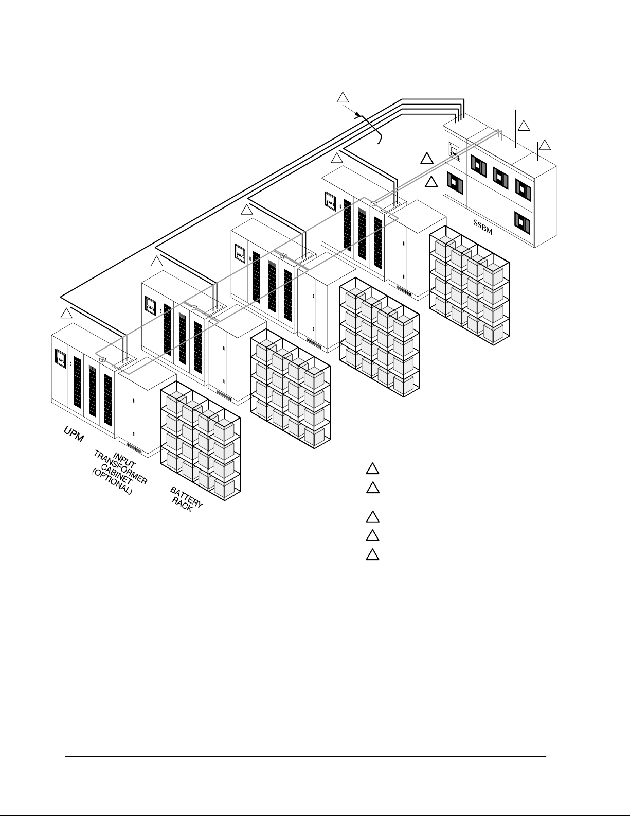
have safety shields behind the doors for hazardous voltage protection. Figure 1
shows a typical Parallel Capacity/Redundant System.
Powerware 9315 Parallel Capacity/Redundant System with PHP SSBM
164201373 Rev. A 092402
i
Page 14
2
4
3
1
1
1
1
5
5
NOTE: 1. Accommodates one to eight UPMs.
Four UPM system shown.
2. The input transformer cabinet may be
installed on either the left or the right
side of the UPM cabinet.
3. Refer to the Powerware 9315 UPS
Installation manual provided with the
UPMs, for UPM, battery, and optional
input transformer installation
information.
4. Actual S SBM physical arrangement and
cable connection locations may differ
from that shown. See enclosed
switchboard vendor drawings for
details.
Figure 1. Typical Parallel Capacity/Redundant System with SSBM
ii
UTILITY POWER INPUT TO UPM
1
UPM OUTPUT TO SSBM INPUT
2
*See Table N of Appendix A for UPM
Output Conductor Sizing.
3
SSBM OUTPUT TO CRITICAL LOAD
4
UTILITY POWER INPUT TO BYPASS BUS
5
POWERNET DUAL REDUNDANT NETWORK
SSBM INTERFACE -- TERMINAL BLOCK TB1
UPM INTERFACE -- TERMINAL BLOCK TB1
FOR 9315--625/750 UPM ONLY:
ALSO INCLUDES DUAL REDUNDANT
NETWORK POWER SUPPLY
SBM INTERFACE -- TB7
UPM INTERFACE -- CANA & CANB
Powerware 9315 Parallel Capacity/Redundant System with PHP SSBM
164201373 Rev. A 092402
Page 15

Basic System Configurations
The flowing Parallel Capacity/Redundant system configurations are possible with the
PowerHandler Plus Switchboard System Bypass Module (SSBM):
• SSBM with Temporary Load Bank Tabs, two or more UPS modules, and one
battery rack for each module
• SSBM with Temporary Load Bank Tabs, two or more UPS modules, and one
common battery rack
• SSBM with Temporary Load Bank Tabs, two or more UPS modules, one battery
rack for each module, and an input transformer
• SSBM with Temporary Load Bank Tabs, two or more UPS modules, one
common battery rack, and an input transformer
• SSBM with Temporary Load Bank Tabs, optional System Maintenance Bypass
(SMB), two or more UPS modules, and one battery rack for each module
• SSBM with Temporary Load Bank Tabs, optional System Maintenance Bypass
(SMB), two or more UPS modules, and one common battery rack
• SSBM with Temporary Load Bank Tabs, optional System Maintenance Bypass
(SMB), two or more UPS modules, one battery rack for each module, and an
input transformer
• SSBM with Temporary Load Bank Tabs, optional System Maintenance Bypass
(SMB), two or more UPS modules, one common battery rack, and an input
transformer
The optional System Maintenance Bypass (SMB) is available with electrical
interlocks, or electrical interlocks with Redundant CBP control.
You can enhance any of these system configurations by adding optional
accessories, such as a Remote Monitor Panel (RMP), Relay Interface Module (RIM),
Supervisory Contact Module (SCM), or Remote Emergency Power Off (EPO) control.
Powerware 9315 Parallel Capacity/Redundant System with PHP SSBM
164201373 Rev. A 092402
iii
Page 16

Using This Manual
The information in this manual is divided into the sections and chapters listed.
The system you are installing dictates which parts of this manual you should read.
Everyone should read the Introduction, Chapters 1 and 2 and Chapters 7 through
12:
Introduction
The Introduction provides a brief description of the Parallel Capacity/Redundant
system, a description of the content of each chapter, safety, text conventions
used in the manual and reference information.
Section I
• Chapter 1 -- Getting Started -- tells you how to prepare your site for the
installation of your Parallel Capacity/Redundant system. It discusses
equipment environmental requirements, inspecting, and unpacking cabinets.
• Chapter 2 -- Installing the Parallel Capacity/Redundant System -- describes
how to install the SSBM and provides references for installing UPMs and
optional equipment.
• Chapter 3 -- Installing a Remote EPO Control -- contains information for
installing the optional Remote Emergency Power Off (EPO) control.
• Chapter 4 -- Installing a Remote Monitor Panel -- contains information for
installing the optional Remote Monitor Panel (RMP).
• Chapter 5 -- Installing a Relay Interface Module -- contains information for
installing the optional Relay Interface Panel (RIM).
• Chapter 6 -- Installing a Supervisory Contact Module -- contains information
for installing the optional Supervisory Contact Module (SCM).
Section II
• Chapter 7 -- Understanding Parallel Capacity/Redundant Operation --
provides information on understanding parallel operation.
• Chapter 8 -- Operational Controls and Features -- describes the standard
and optional operational features and controls of the parallel
capacity/redundant system.
• Chapter 9 -- Using the Control Panel -- describes the controls and indicators
found on the Control Panel and shows the various information screens
displayed on the LCD screen.
• Chapter 10 -- Operating Instructions for the Parallel Capacity/Redundant
System -- contains startup and shutdown procedures for the Parallel
Capacity/Redundant system.
• Chapter 11 -- Using Features and Options -- contains descriptions and
instructions for the Parallel Capacity/Redundant system features and options.
• Chapter 12 -- Responding to System Events -- lists all the alarm, messages
and notices that occur during operation of the Parallel Capacity/Redundant
system.
iv
Powerware 9315 Parallel Capacity/Redundant System with PHP SSBM
164201373 Rev. A 092402
Page 17

• Chapter 13 -- Serial Communications -- describes the serial communications
features of the Parallel Capacity/Redundant system.
• Chapter 14 -- Remote Notification -- contains instructions for using the
remote notification feature of the Parallel Capacity/Redundant system.
• Chapter 15 -- Maintaining the Parallel Capacity/Redundant System --
contains maintenance instructions for the Parallel Capacity/Redundant system.
• Chapter 16 -- Product Specifications -- provides detailed specifications for
the Parallel Capacity/Redundant system.
• Appendix A -- Customer Information -- contains important information on
wiring requirements and recommendations, and important diagrams of the
mechanical details and electrical access.
Read through each procedure before you begin. Perform only those procedures
that apply to the Parallel Capacity/Redundant system you are installing or
operating.
Conventions Used in This Manual
The text in this manual uses these conventions:
• Bold type highlights important concepts in discussions, key terms in
procedures, and menu options.
• Italic type highlights notes and new terms where they are defined.
• Rectangular boxes containing bold type are warnings or cautions that pertain to
the Parallel Capacity system or its electrical connections.
In this manual, the term SSBM refers only to the Switchboard System Bypass Module
and its internal elements. The term Parallel Capacity/Redundant system refers to the
entire power protection system—the SSBM, UPS modules, battery racks and options
or accessories installed.
Powerware 9315 Parallel Capacity/Redundant System with PHP SSBM
164201373 Rev. A 092402
v
Page 18

Safety Considerations
The UPS cabinet and SSBM enclosures are designed for industrial or computer
room applications, and contain safety shields behind the doors. However, the
parallel redundant system is a sophisticated power system and should be handled
with appropriate care, following these guidelines:
• Keep surroundings clean and free from excess moisture.
• Do not operate the parallel redundant system close to gas or electric heat
sources.
• The system is not intended for outdoor use.
• The operating environment should be maintained within the parameters
stated in this manual and the Powerware 9315 Operation manual provided
with the UPS system.
• Keep the cabinet doors closed to ensure proper cooling airflow and to
protect personnel from dangerous voltages inside the unit.
• The parallel redundant system contains its own power source. Lethal
voltages are present even when the UPS is disconnected from utility
power.
WARNING:
Only AUTHORIZED SERVICE PERSONNEL should perform service or
maintenance on the parallel redundant system.
If service or routine maintenance is required:
• Ensure all power is disconnected before performing installation or service.
• Ensure the area around the parallel redundant system is clean and
uncluttered.
• Battery cabinet maintenance or battery replacement should be performed
only by authorized service personnel.
• Observe all DANGER, CAUTION, and WARNING notices affixed to the
inside and outside of the equipment.
• Refer to the more detailed safety precautions described in the Powerware
9315 Operation manual provided with the UPS system.
vi
Powerware 9315 Parallel Capacity/Redundant System with PHP SSBM
164201373 Rev. A 092402
Page 19

For More Information
This manual describes how to install and operate your Parallel Capacity/Redundant
system. For more information about the installation and operation of the UPS
modules, refer to the following:
164201037 Powerware
164201118 Powerware
Provides installation instructions for the UPS cabinet, and
optional components and accessories. Site preparation,
planning for installation, and wiring and safety information are
supplied. Detailed illustrations of cabinets and optional
accessories, including dimensional and connection point
drawings are provided.
164201036 Powerware
164201119 Powerware
Describes the UPS cabinet Control Panel and Monitor Panel,
and explains the functions of the UPS; discusses the standard
features of the UPS and optional accessories; provides
procedures for starting and stopping the UPS, and information
about maintenance and responding to system events.
9315 (200 kVA--- 300 kVA) UPS Installation
9315 (400 kVA--- 500 kVA) UPS Installation
9315 (200 kVA--- 300 kVA) UPS Operation
9315 (400 kVA--- 500 kVA) UPS Operation
A ls o d e s c r i be d a r e t he R S --- 4 85 an d R S --- 2 32 se r ia l
communications capabilities of the UPS system; discusses the
two communications ports on the Customer Interface Panel
inside the UPS and how to connect optional remote accessories
to your UPS system; provides information about enabling,
disabling, and customizing building alarms.
164201244 Powerware
Installation/Operation
Provides installation instructions for the UPS cabinet, and
optional components and accessories. Site preparation,
planning for installation, and wiring and safety information are
supplied. Detailed illustrations of cabinets and optional
accessories, including dimensional and connection point
drawings are provided.
Describes the UPS cabinet Control Panel and Monitor Panel,
and explains the functions of the UPS; discusses the standard
features of the UPS and optional accessories; provides
procedures for starting and stopping the UPS, and information
about maintenance and responding to system events.
A ls o d e s c r i be d a r e t he R S --- 4 85 an d R S --- 2 32 se r ia l
communications capabilities of the UPS system; discusses the
two communications ports on the Customer Interface Panel
inside the UPS and how to connect optional remote accessories
to your UPS system; provides information about enabling,
disabling, and customizing building alarms.
9315 (500 kVA--- 750 kVA) UPS
Contact your local Powerware Field Service office for information on how to obtain
copies of this manual.
Powerware 9315 Parallel Capacity/Redundant System with PHP SSBM
164201373 Rev. A 092402
vii
Page 20

Getting Help
If you have a question about any of the information in this manual, or if you have
a question this manual does not answer, please call Powerware Corporation Field
Service:
United States 1-800-843-9433
Canada 1-800-461-9166
Outside the U.S. Call your local representative
viii
Powerware 9315 Parallel Capacity/Redundant System with PHP SSBM
164201373 Rev. A 092402
Page 21

Section I
Installation
Powerware 9315 Parallel Capacity/Redundant System with PHP
SSBM
164201373 Rev. A 092402
Page 22

This Page Intentionally Left Blank.
Powerware 9315 Parallel Capacity/Redundant System with PHP
164201373 Rev. A 092402
SSBM
Page 23

n
Getting Started
1.1 Installing the UPS
The Switchboard System Bypass Module (SSBM) and UPMs of the Parallel
Capacity/Redundant system are shipped on separate pallets. Use a forklift or pallet
jack to move the packaged cabinets to the installation site, or as close as possible
to the site, before unloading from the pallet.
This is the basic sequence of the installation steps:
1. Create an installation plan for the Parallel Capacity/Redundant system
(Chapter 1).
2. Prepare your site for the Parallel Capacity/Redundant system (Chapter 1).
3. Inspect, unpack, and unload the SSBM (Chapter 1).
4. Inspect, unpack, and unload the UPMs (refer to the applicable Powerware
9315 Installation manual provided with the UPM).
1
5. Wire the system (refer to Chapter 2 and the applicable Powerware 9315
Installation manual provided with the UPM).
6. Install features, accessories, and/or options, as applicable (Chapter 3).
7. Complete the Installation Checklist (Chapter 2).
8. Have authorized service personnel perform preliminary operational checks and
startup.
NOTE: Startup and operational checks should be performed only by authorized
service personnel. This service is usually offered as part of the sales
contract for your Parallel Capacity/Redundant system.Contactservicein
advance (usually a two week notice is required) to reserve a preferred
startup date.
1.1.1 Creating an Installation Plan
Before beginning to install the Parallel Capacity/Redundant system, read and
understand how this manual applies to the system being installed. Use the
procedures and illustrations in the following chapters to create a logical plan for
installing the system. It is important to note that UPM installation procedures are
contained in the applicable Powerware 9315 Installation manual provided with the
UPMs. First understand how to install the UPMs before installing the SSBM. The
information in Chapter 2 of this manual provides a guide to installation of the SSBM
to the UPMs.
Powerware 9315 Parallel Capacity/Redundant System with PHP SSBM
164201373 Rev. A 092402
1--1
Page 24

1.1.2 Preparing Your Site
For your Parallel Capacity/Redundant system to operate at peak efficiency, your
installation site should meet the environmental parameters outlined in the
operator’s manual for the SSBM and UPMs. If you intend to operate the system at
an altitude higher than 1500 meters (5000 feet), contact your local sales or service
office for important information about high altitude operation. The operating
environment must meet the size and weight requirements shown in the enclosed
vendor drawings.
The basic environmental requirements for operation of the Parallel
Capacity/Redundant system are:
Ambient Temperature Range: 0 --- 2 5 ˚C (32---77˚F)
Recommended Operating Range: 20---25˚C ( 6 8 --- 7 7 ˚F)
Maximum Relative Humidity: 95% noncondensing
The UPM cabinets use forced air cooling to regulate internal component temperature.
The SSBM, battery and optional component cabinets use convection cooling to
regulate internal component temperature. Air inlets are in the front of the cabinet, and
outlets are in the top. You must allow clearance in front of and above each cabinet for
proper air circulation.
1.1.3 Environment Considerations
The life of the Parallel Capacity/Redundant system will be adversely affected if the
installation does not meet the following guidelines:
1. The system must be installed on a sealed concrete pad or a sealed concrete
floor.
2. The system must be installed in a temperature-controlled indoor area free of
conductive contaminants.
1.1.4 Preparing for Wiring the Parallel Capacity/Redundant
System
NOTE: The external wiring and conduit sizings described in this manual are only
provided as a recommended approach. Many design considerations may
require an external wiring and conduit configuration much different than the
examples provided in this manual. Applicable local codes and national
codes must be followed.
Table A in Appendix A covers SSBM and SMB power cabling for a 3
∅
system. Table A is based on the entire 3
ambient and the use of 90_C copper wire. The 500kcmil and 600kcmil cables
are used as examples.
Table B in Appendix A covers SSBM and SMB power cabling for a 3
system. Table B is based on the entire 3
ambient, use of 90_C copper wire and a 0.80 derating factor because there are
more than three current carrying conductors in a raceway (NEC Table 310 ---16
and Notes). The 500kcmil and 600kcmil cables are used as examples.
/3Wsystembeingina25_C room
∅
/4Wsystembeingina25_C room
∅
∅
/3W
/4W
1--2
Powerware 9315 Parallel Capacity/Redundant System with PHP SSBM
164201373 Rev. A 092402
Page 25

NOTE: Two tables in Appendix A cover the cables running from the UPM output
terminals to the SSBM module input terminals E8 (
∅
A), E9 (∅B), E10 (∅C),
and E4 (Neutral)
Table O covers the recommended wiring and conduit sizing based on the
applicable Powerware 9315 Installation manual provided with the UPM. Using
the noted power wiring, Table O shows the number of UPMs that can be
connected toeach SSBM model. This number of UPMs is limitedby thenumber
of cables connections for the SSBM module input terminals E8, E9, E10, and
E4showninTableCinAppendixA.
If the parallel capacity/redundant system requires the connection of more
UPMs to the SSBM than is shown in T a ble O, refer to Table P. Table P covers
the recommended wiring and conduit sizing to support connection of the
maximum number of UPMs (up to eight) for each SSBM model.
CAUTION:
The UPM output wiring configurations in Table O in Appendix A do not
that shown in the applicable Powerware 9315 UPS Installation manual. Review
the planned UPM output power cables to ensure the planned cabling is
compatible with the available number of cable connections at both the UPM
and SSBM terminals.
match
Powerware UPMs are rated for operation in a 40_C room ambient. For this
∅
reason, Table O and P are based on the entire 3
/ 3W system being housed
in a 40_C room ambient, the use of 90_C copper wire and a 0.80 derating factor
because there are more than three current carrying conductors in a raceway
(NEC Table 310 ---16 and Notes).
Refer to the applicable Powerware 9315 Installation manual provided with the
UPM for all other UPM power cable requirements (AC input, DC input, and
grounding)
NOTE: Review Table C in Appendix A to ensure the planned power cable
configuration is compatible with the available number of cable connections
at each SSBM and SBM terminal.
NOTE: If additional cable connections are required, consider using FCI HYSTACK
Type ASA --- U adapters. HYSTACK P/N ASA250U covers NEMA 2-hole
terminals for wire siz es from #8 AWG to 250kcmil. HYSTACK P/N ASA800U
covers NEMA 2-hole terminals for wire sizes from #8 AWG to 800kcmil.
Care must be taken in HYSTACK adapters to ensure the required
phase-to-phase clearance of 1 inch and phase-to-ground clearance of
1 inch (1.5 inches in Canada) is maintained.
For external wiring, including the recommended minimum AWG size of external
wiring, see Tables A, B, O, and P in Appendix A. The power wiring connections for
this equipment are rated at 90˚C. Ifwireisruninanambienttemperaturegreater
than noted above, higher temperature and/or larger size wire may be necessary.
Control wiring for PowerNet, EPO and optional accessories (such as building
alarms, monitoring interface and Maintenance Bypass control) should be
connected at the customer interface panel at the top of the SSBM Powernode
Panel (A1), which is shown in drawing 164201373---12 in Appendix A.
Powerware 9315 Parallel Capacity/Redundant System with PHP SSBM
164201373 Rev. A 092402
1--3
Page 26
1.1.5 Inspecting and Unpacking Each Cabinet
NOTE: Refer to the applicable Powerware 9315 Installation manual provided with
the UPMs for UPM unpacking instructions.
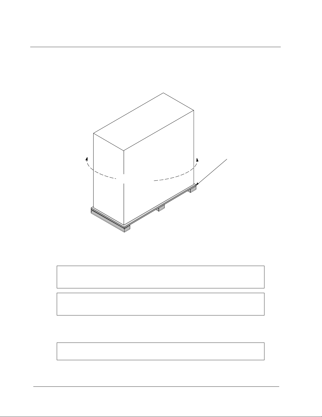
The first task in preparing for installation is inspecting and unpacking the SSBM.
The SSBM is shipped in sections which are bolted to wooden pallets and protected
with outer protective packaging material as shown in Figure 1---1 and a plastic inner
covering.
WOODEN
P ALLET
OUTER
PACKA G I NG
1--4
Figure 1 ---1. Cabinets as Shipped, with Outer Packaging and Pallet
Carefully inspect the outer packaging for evidence of damage during transit.
1.
CAUTION:
Do not install a damaged cabinet. Report any damage to the carrier and
contact your local sales or service office immediately.
CAUTION:
Only insert the forklift jacks where “FORK HERE” signs appear on cabinet
packaging.
2. Use a forklift or other material handling equipment to move the cabinet to a
convenient unpacking area. Insert the forklift jacks between the raised
supports on the bottom of the pallet.
CAUTION:
Do not tilt cabinets more than 10 degrees from vertical.
3. Set each pallet on a firm, level surface, allowing a minimum clearance of
4.6m (15 ft) on each side for removing the cabinets from the pallets.
Powerware 9315 Parallel Capacity/Redundant System with PHP SSBM
164201373 Rev. A 092402
Page 27

4. Remove the protective plastic wrap and cardboard covering from the cabinets,
using a knife blade no longer than 25 mm (1 in.).
5. Discard or recycle the wrapping materials in a responsible manner .
6. After removing the protective covering, inspect the contents for any evidence
of physical damage, and compare each item with the Bill of Lading. If damage
has occurred or shortages are evident, contact Powerware Corporation
Customer Service Department immediately to determine the extent of the
damage and its impact upon further installation.
NOTE: While awaiting installation, protect the unpacked SSBM and UPS cabinets in
an indoor area free from moisture, dust, and other harmful contaminants in a
rodent-free area with moderate temperatures.
Powerware 9315 Parallel Capacity/Redundant System with PHP SSBM
164201373 Rev. A 092402
1--5
Page 28

This Page Intentionally Left Blank.
1--6
Powerware 9315 Parallel Capacity/Redundant System with PHP SSBM
164201373 Rev. A 092402
Page 29

Installing the Parallel
Capacity/Redundant System
2.1 Preliminary Installation Information
WARNING:
Installation should be performed only by qualified personnel.
Refer to the following while installing the Parallel Capacity/Redundant system:
• Appendix A of this manual for installation drawings and additional installation
notes.
• Dimensions in this manual are in millimeters and inches.
• Do not tilt the Switchboard System Bypass Module (SSBM), UPMs or other
cabinets more than
• The conduit landing plates are to be removed to add conduit landing holes as
required. Plate material is generally 16 gauge steel (0.06 in. thick).
¦10˚during installation.
2
• The Remote Emergency Power Off (EPO) and the EMERGENCY UPM OFF
pushbuttons open all breakers in the SSBM, shut down the UPMs, and isolates
power from your critical load. Local electrical codes may also require tripping
protective devices upstream from the UPMs.
• The SSBM cabinet must be installed on a level, sealed concrete pad or floor.
The floor or pad must be strong enough to prevent sagging or cracking from
the SSBM weight. If the floor area is subject to vibrations, special mounting
must be provided to prevent transmitting the vibrations to the SSBM.
• If perforated floor tiles are required for ventilation, place them in front of the
UPMs.
• Details about control wiring are provided in each procedure for connecting
options and features. Drawings 164201373---4 through 164201373---7 in
Appendix A identify the control wiring terminations.
Powerware 9315 Parallel Capacity/Redundant System with PHP SSBM
164201373 Rev. A 092402
2--1
Page 30

2.2 Installing the Switchboard System Bypass Module
The SSBM is shipped in separate shipping sections. Each shipping section is
bolted to a wooden pallet.
WARNING:
The SSBM shipping sections are extremely heavy. If unloading instructions are
not closely followed, the sections may tip and cause serious injury.
1. Find section labels on each shipping section. Install the shipping sections in
numerical order.
CAUTION:
Only insert the forklift jacks where “FORK HERE” signs appear on cabinet
packaging.
2. Move the SSBM to final installed location using forklift jacks between the raised
supports on the bottom of the unit.
3. Remove side panels from SSBM cabinet to gain access to hardware securing
cabinet to pallet.
4. Remove hardware securing cabinet to pallet.
CAUTION:
Lift only at lifting eyes or cabinet damage may occur..
5. Attach suitable hoist to SSBM lifting eyes and lift SSBM cabinet until the
cabinet bottom clears the pallet by approximately 3 mm (1/8 in.).
6. Once SSBM cabinet is clear of the pallet, pull the pallet from under the UPS
cabinet. Discard or recycle them in a responsible manner.
7. Carefully lower the SSBM cabient until the cabinet base contacts the floor.
8. Remove lifting eyes from SSBM cabient.
9. With the shipping section in their final locations, align SSBM shipping sections.
10. Bolt shipping sections together with supplied hardware and anchor to floor or
pad.
11. Install all Bypass, Critical, and Neutral Bus shipping split bus plates. Torque
supplied hardware to 30 ft-lbs.
12. Install all Ground Bus shipping split bus plates. Tighten supplied hardware.
13. Run section wiring harnesses through wire trough in rear cabling area and
pass into Control section through grommeted opening.
14. Insert harness plugs into match caps in the bottom of the A1 Panel in the
Control Section.
2--2
Powerware 9315 Parallel Capacity/Redundant System with PHP SSBM
164201373 Rev. A 092402
Page 31

2.3 Installing Optional System Maintenance Bypass (SMB)
The System Maintenance Bypass is shipped as a separate shipping section. The
SMB section is bolted to a wooden pallet.
CAUTION:
The SMB is heavy. If unloading instructions are not followed closely, the
cabinet may tip and cause serious injury or damage. Do not tilt cabinets more
than 10 degrees from vertical.
1. Find section label on SMB. Install the SMB in numerical order with SSBM
shipping sections.
CAUTION:
Only insert the forklift jacks where “FORK HERE” signs appear on cabinet
packaging.
2. Move the SMB to final installed location on the right side of the SSBM shipping
sections using forklift jacks between the raised supports on the bottom of the
unit.
3. Remove side panel from SMB cabinet to gain access to hardware securing
cabinet to pallet.
4. Remove hardware securing cabinet to pallet.
CAUTION:
Lift only at lifting eyes or cabinet damage may occur.
5. Attach suitable hoist to SMB lifting eyes and lift SMB cabinet until the cabinet
bottom clears the pallet by approximately 3 mm (1/8 in.).
6. Once SMB cabinet is clear of the pallet, pull the pallet from under the UPS
cabinet. Discard or recycle them in a responsible manner.
7. Carefully lower the SMB cabient until the cabinet base contacts the floor.
8. Remove lifting eyes from SMB cabient.
9. With the SMB in its final location, align with SSBM shipping sections.
10. Bolt SMB to SSBM with supplied hardware and anchor to floor or pad.
11. Install all Bypass, Critical, and Neutral Bus shipping split bus plates. Torque
supplied hardware to 30 ft-lbs.
12. Install all Ground Bus shipping split bus plates. Tighten supplied hardware.
13. Run SMB wiring harnesses through wire trough in rear cabling area and pass
into Control section through grommeted opening.
14. Connect Mate-N-Lock plug and cap at temporary Load Bank current
transformers.
15. Insert harness plugs into matching caps in the bottom of the A1 Panel in the
Control Section.
Powerware 9315 Parallel Capacity/Redundant System with PHP SSBM
164201373 Rev. A 092402
2--3
Page 32

2.4 Installing the Powerware S tatic Switch
Your Switchboard System Bypass Module (SSBM) includes the Powerware static
switch shown below.
SSBM Current
Rating
2500A 2500A Fully Rated Powerware 91 (200)
3000 to 4000A 4000A Fully Rated Powerware 227 (500)
Static Switch
Current Rating
Static Switch
Typ e
Static Switch
Manufacturer
Static Switch
Weight kg (lbs)
2.4.1 Installing a Fully Rated Static Switch (2500A or 4000A)
WARNING:
The SSBM should be shut down prior to installing the static switch.
If the SSBM cannot be shut down, transfer the SSBM to Bypass and manually
open the FBP breaker prior to installing the static switch.
If the SSBM is supplied with a System Maintenance Bypass (SM B), transfer the
SSBM to Maintenance Bypass prior to installing the static switch.
Using an adequate lifting device, install the fully rated static switch in the same
manner as a drawout circuit breaker.
2.5 Installing SSBM or SMB Circuit Breakers
The SSBM and SMB are equipped with General Electric PowerBreakRII drawout
circuit breakers.
Circuit Breaker
SSBM
Current Rating
2500A/100 kAIC 2500A/100 kAIC General Electric 110 (242)
3000A/65 kAIC 3000A/65 kAIC General Electric 110 (242)
3000A/100 kAIC 3000A/100 kAIC General Electric 110 (242)
4000A/65 kAIC 4000A/65 kAIC General Electric 138 (304)
4000A/100 kAIC 4000A/100 kAIC General Electric 138 (304)
Current Rating
(100% Rated)
Circuit Breaker
Manufacturer
Circuit Breaker
Weight kg (lbs)
2.5.1 Installing an SSBM or SMB Circuit Breaker
NOTE: The General Electric installation instructions and user’s guides noted below
are available at the GE Industrial Systems Publications Library website of
http://www.geindustrial.com/cwc/library.
Using an adequate lifting device, install the SSBM and SMB circuit breakers per
instructions in GE Document GEH---6271, Installation Instructions for PowerBreak
Circuit Breakers, Draw-Out 800 --- 4000 Ampere Frames.
t
II
2--4
Powerware 9315 Parallel Capacity/Redundant System with PHP SSBM
164201373 Rev. A 092402
Page 33

2.5.2 Setting the Power+ Trip Unit
As received, the long-time delay, long-time pickup, and instantaneous trip settings are
at their maximum values. It is the user’s responsibility to install the long-time delay,
long-time pickup, and instantaneous trip settings which are in compliance with their
overall coordination study.
Using GE Document DEH--- 049, User’s Guide for the Power+
required long-time delay, long-time pickup, and instantaneous trip settings on all
SSBM and SMB circuit breakers trip units.
NOTE: T h e a p p l i c a b l e t i m e --- c u r r e n t c u r v e i s G E D o c u m en t G E S --- 9 8 9 0 E .
2.6 Installing UPM Cabinets
To install the UPMs, refer to the Powerware 9315 UPS Insatallation manual provided
with the UPMs.
2.7 Installing SSBM Wiring
t
Trip Unit, set the
NOTE: Refer to section 1.1.4 for additional guidance for wiring and conduit
placement.
NOTE: F or SSBM with100 kAIC short circuit rating, power rating must be secured
as shown in drawing 164201373 ---1.
1. Install input power wiring to the SSBM and power wiring between the UPMs,
SSBM, and critical load. Each UPM is individually wired to the SSBM UPM
input bus. Refer to Appendix A of this manual for wiring and termination
requirements and wiring access information.
2. Install control wiring between UPMs and the SSBM. PowerNet network is
wired serially (daisy-chained) between UPMs and SSBM. Wire dual redundant
PowerNet in separate conduits for maximum failure protection. Refer to
Appendix A of this manual for wiring and termination requirements and wiring
access information.
3. If a common UPM battery is being used, a separate DC source disconnect
device must be provided for each UPM. Wire shunt/UV DC disconnect trip
and battery breaker open signals from each UPM to the respective DC source
disconnect.
4. After wiring the Parallel Capacity/Redundant system to the facility power and
critical load(s), be sure to ground the system according to local and/or national
electrical wiring codes, using your own cabling and conduit.
5. Install batteries in accordance with all applicable codes and regulations,
including the National Electrical Code (NEC), Article 480.
Powerware 9315 Parallel Capacity/Redundant System with PHP SSBM
164201373 Rev. A 092402
2--5
Page 34

2.8 Installing Optional SMB Wiring
NOTE: Refer to section 1.1.4 for additional guidance for wiring and conduit
installation.
NOTE: For SMB with100 kAIC short circuit rating, power rating must be secured as
shown in drawing 164201373 ---1.
Install power wiring to the SMB and between the SMB and critical load. Refer to
Appendix A of this manual for wiring and termination requirements and wiring access
information.
2.9 Preparing for Installing Optional Accessories
If you are installing optional accessories, such as a Remote Monitor Panel (RMP),
a Relay Interface Module (RIM), a Supervisory Contact Module (SCM),oraRemote
Emergency Power Off (EPO), you must install conduit between each device and the
UPS cabinet for wiring these options. Refer to Appendix A for the locations of the
interface points within the SSBM cabinet.
TopreparetheSSBMforwiringtoanRMP,RIM,SCM,orRemoteEPO:
1. Be sure the Parallel Capacity/Redundant system is turned off and all power
sources are removed. (See the operation section of this manual for shutdown
instructions.)
2. Remove the access plate on top of the SSBM control section to gain access to
the Customer Interface Panel (refer to Appendix A for location of the access
plate).
3. RefertoChapters3,4,5,or6asapplicableforinstallationinstructions.
2.10 Initial Startup
Startup and operational checks should be performed only by authorized service
personnel. Contact service in advance (usually a two week notice is required) to
reserve a preferred startup date.
2.11 Completing the Installation Checklist
The final step in installing your Parallel Capacity/Redundant system is completing
the following Installation Checklist. This checklist ensures that you have
completely installed all hardware, cables, and other equipment. Completing all
items listed on the checklist will ensure a smooth installation. You should make a
copy of the Installation Checklist before filling it out, and retain the original.
After your installation is complete, a service representative will be able to verify the
operation of your Parallel Capacity/Redundant system and commission it to
support your critical load. The service representative cannot perform any
installation tasks other than verifying software and operating setup parameters.
Service personnel may request a copy of the completed Installation Checklist to be
sure you have completed all applicable equipment installation.
NOTE: The Installation Checklist MUST be completed prior to starting the Parallel
Capacity/Redundant system for the first time.
2--6
Powerware 9315 Parallel Capacity/Redundant System with PHP SSBM
164201373 Rev. A 092402
Page 35

2.12 Installation Checklist
-All packing materials and restraints have been removed from each cabinet.
-Each cabinet in the Parallel Capacity/Redundant system is placed in its installed
location.
-A ground bond is installed between any cabinets that are bolted together.
-All switchboards, conduits, and cables are properly routed to the SSBM, UPMs and
auxiliary cabinets.
-All power cables are properly terminated.
-A ground conductor is properly installed.
-If neutral connection is used, no other N---G bonds exist downstream from the UPMs.
-Battery cables and harness are terminated on E4 and E5.
-Internal battery cabinet connections have been completed (bus bars, plugs, etc.).
-Shunt trip signal wiring is connected from UPMs to battery breaker(s).
-Air conditioning equipment is installed and operating correctly.
-The area around the installed Parallel Capacity/Redundant system is clean and
dust-free. (It is recommended that the Parallel Capacity/Redundant system be
installed on a sealed concrete pad or a sealed concrete floor.)
-Adequate work space exists around the SSBM, UPMs and other cabinets.
-Adequate lighting is provided around the Parallel Capacity/Redundant system.
-A 120VAC service outlet is located within 25 feet of the Parallel Capacity/Redundant
system.
-All circuit breaker trip units settings have been completed per the user’s coordination
study.
-Each Remote Monitor Panel (RMP) is mounted in its installed location. (OPTIONAL)
-The control wiring for each RMP is terminated inside the UPS cabinet. (OPTIONAL)
-The Remote Emergency Power Off (EPO) device is mounted in its installed location
and its wiring terminated inside the SSBM. (OPTIONAL)
-Summary alarms and/or building alarms are wired appropriately. (OPTIONAL)
-A Relay Interface Module (RIM) is mounted in its installed location and its wiring is
terminated inside the SSBM. (OPTIONAL)
-A remote battery disconnect control is mounted in its installed location and its wiring is
terminated inside the UPS and battery cabinet. (OPTIONAL)
-Startup and operational checks performed by authorized service personnel.
Powerware 9315 Parallel Capacity/Redundant System with PHP SSBM
164201373 Rev. A 092402
2--7
Page 36

Notes
________________________________________________________________________________
________________________________________________________________________________
________________________________________________________________________________
________________________________________________________________________________
________________________________________________________________________________
________________________________________________________________________________
________________________________________________________________________________
________________________________________________________________________________
________________________________________________________________________________
________________________________________________________________________________
________________________________________________________________________________
________________________________________________________________________________
________________________________________________________________________________
2--8
Powerware 9315 Parallel Capacity/Redundant System with PHP SSBM
164201373 Rev. A 092402
Page 37

Installing a Remote EPO Control
The Remote EPO control arrives as shown in Figure 3 ---1. See Drawing
164201373---7 in Appendix A for wiring information, enclosure dimensions,
side views, and knockout patterns.
3
UNINTERRUPTIBLE POWER SYSTEM
to SBM to other equipment
EMERGENCY OFF
Figure 3 --- 1. Remote EPO Control
NOTE: Before installing an Remote EPO, be sure you have prepared the SSBM
according to the instructions in Chapter 2.
Powerware 9315 Parallel Capacity/Redundant System with PHP SSBM
164201373 Rev. A 092402
3--1
Page 38

To install a Remote EPO control:
)
Twistedwires(2)
1. Securely mount the Remote EPO station. Recommended locations include
operator’s consoles or exit doors.
2. Install wiring from the Remote EPO station using ½-in. conduit through the
cable entry panels on the top of the SSBM.
3. Connect the Remote EPO wiring as shown in Tables 3---1 and 3 ---2:
Table 3---1. Remote EPO Wire Terminations
From Remote
EPO Station(s)
To Cu st ome r Int erf ac e
Panel in SSBM
T B1 --- 4 T B2 --- 1
T B1 --- 5 T B2 --- 2
Table 3---2. Remote EPO
REMOTE
EPO
SWITCH
TWISTED
WIRES (2)
Remote EPO switch rating is 24 VDC.
1 Amp minimum if supplied by user.
Remarks
Twisted wires(2
1 4 --- 1 8 g au g e
1
TB2
2
NOTE: This switch must be a dedicated
switch not tied into any other circuits.
4. If you are installing multiple Remote EPO stations, wire additional stations in
parallel with the first Remote EPO.
5. If required, install ½-in. conduit and wiring from the Remote EPO station to trip
circuitry of upstream protective devices. A normally open contact is provided,
asshowninTable3---2. RemoteEPOswitchwiringmustbeinaccordance
with UL Class 1 requirements.
6. Secure the SSBM by reversing all steps taken to prepare it for Remote EPO
installation.
3--2
Powerware 9315 Parallel Capacity/Redundant System with PHP SSBM
164201373 Rev. A 092402
Page 39

Installing a Remote
Monitor Panel
4.1 Installation Procedures
As an option, you can install Remote Monitor Panels (RMPs) to monitor the
operation of the Parallel Capacity/Redundant system from virtually any location
within your facility, up to 500 feet from the Switchboard System Bypass Module
(SSBM). You can flush-mount or surface-mount an RMP on a desktop or on a wall,
wherever you have a serial interface line. A maximum of two monitoring
accessories (RMPs, RIMs, or SCMs) can be installed. See Table 4---1 for the
number of accessories permitted. Figure 4 ---1 shows an RMP. Drawing
164201373---8 in Appendix A shows the enclosure dimensions and knockout
patterns.
Table 4 --- 1. Optional Monitoring Accessories
Number and Type of Accessories Permitted
Remote Monitor Panel Relay Interface Module Supervisory Contact Module
2 — —
44
— 2 —
— — 2
1 1 —
1 — 1
— 1 1
Powerware 9315 Parallel Capacity/Redundant System with PHP SSBM
164201373 Rev. A 092402
4--1
Page 40

FLUSH MOUNT
SURFACE MOUNT
(FOR HANGING)
WIRES MUST
BE TWISTED
4--2
Figure 4 --- 1. Remote Monitor Panel (RMP)
Powerware 9315 Parallel Capacity/Redundant System with PHP SSBM
164201373 Rev. A 092402
Page 41

NOTE: Before installing an RMP, be sure you have prepared the SSBM according to
the instructions in Chapter 2.
4.2 To install an RMP:
1. Securely mount the RMP(s).
2. Install wiring from the RMP using ½-in. conduit through the cable entry panels
in the top of the SSBM control section (refer to the enclosed switchboard
vendor drawings for the location of the conduit landing plate).
3. In the spare parts kit, locate the RMP adapter cable assembly
(see Figure 4---2). Mate the DB---9 connector on the back of the terminal block
to the DB--- 9 connector (Port 1) on the Customer Interface Panel of the SSBM
(refer to Drawing 164201373---4 in Appendix A). Use two screws from the
spare parts kit to secure the terminal block bracket to the Customer Interface
Panel.
Connect to
Po r t 1 (D B --- 9 ) o n
Customer Interface Panel
Figure 4 --- 2. Terminal Block Bracket
FUSE
TERMINAL
BLOCK
(TB3)
Powerware 9315 Parallel Capacity/Redundant System with PHP SSBM
164201373 Rev. A 092402
4--3
Page 42

4. Connect RMP wiring to the terminal block using terminations shown in
1
2TURNSPER
3INCHES
1
2TURNSPER
3INCHES
Ta b l e 4 --- 2 .
Table4---2. RMPWireTerminations
From RMP A To S SBM Remarks
T B1 --- 4
T B1 --- 5
T B1 --- 6
T B1 --- 7
From RMP B (if used) To SSB M Remarks
T B1 --- 4
T B1 --- 5
T B1 --- 6
T B1 --- 7
T B3 --- 1
T B3 --- 2
T B3 --- 3
T B3 --- 4
T B3 --- 5
T B3 --- 6
T B3 --- 7
T B3 --- 8
TWISTED WIRES (4)
--3INCHES
TWISTED WIRES (4)
--3INCHES
5. To check the operation of the RMP, ensure that the Parallel
Capacity/Redundant system is supplying the load via the inverters or bypass.
If the indicators on the RMP show the appropriate status, then it is operating
correctly.
If the communications link between the SSBM and the RMP is not present, the
RMP will self-test (all indicators flash and the horn beeps at one-second
intervals). If this occurs, check all harness connectors and the fuse for proper
seating. If all connections are secure but the RMP continues to self-test,
replacethefusewiththespareincludedinthehardwarekit. Ifthisdoesnot
correct the problem, contact your local field service office for verification that
the RMP is working correctly.
6. To test the indicator lamps, press the horn silence button and hold it for
3 seconds. All lamps should light, and the horn will sound continuously
until you release the button.
7. Repeat steps 1, 2, and 4 through 6 for each RMP you are installing.
8. If you are installing an RIM or SCM in addition to an RMP, proceed to Chapter 5
or 6, respectively; otherwise, secure the SSBM by reversing the steps
contained in procedure “To Prepare the SSBM for Wiring to an RMP, RIM,
SCM, or Remote EPO” of Chapter 2.
4--4
Powerware 9315 Parallel Capacity/Redundant System with PHP SSBM
164201373 Rev. A 092402
Page 43

Installing a Relay
Interface Module
5.1 Installation Procedures
The optional Relay Interface Module (RIM) uses relay contact closures to indicate
the operating status and alarm condition of the Parallel Capacity/Redundant
system. The module uses an RS422 serial interface line and may support up to
eight critical loads. A maximum of two monitoring accessories (RMPs, RIMs, or
SCMs) can be installed. Refer to Chapter 4, Table 4 ---1 for the number of
accessories permitted. Figure 5---1 shows the RIM with its four 15-pin connectors
labeled J1 through J4. Drawing 164201373 ---9 in Appendix A outlines the
enclosure dimensions.
5
FLUSH MOUNT
SURFACE
MOUNT
FOR HANGING
Relay Interface Module
J1 J2 J3 J4
15-PIN D-SUB
CONNECTORS
CONTINUES
AT UPS
Figure 5---1. Relay Interface Module
NOTE: Before installing an RIM, be sure you have prepared the S SBM according to
the instructions in Chapter 2.
Powerware 9315 Parallel Capacity/Redundant System with PHP SSBM
164201373 Rev. A 092402
5--1
Page 44

5.2 To install a RIM :
1. Securely mount the RIM.
2. Install wiring from the RIM using ½-in. conduit through the cable entry panels
in the top of the SSBM control section (refer to the enclosed switchboard
vendor drawings for the location of the conduit landing plate).
3. If not already installed, locate the RMP adapter cable assembly (see Figure
5---2) in the spare parts kit. Mate the DB---9 connector on the back of the
terminal block to the DB---9 connector (Port 1) on the Customer Interface Panel
of the SSBM (refer to Drawing 164201373---4 in Appendix A). Use two screws
from the spare parts kit to secure the terminal block bracket to the Customer
Interface Panel.
Connect to
Po r t 1 (D B --- 9 ) o n
Customer Interface Panel
FUSE
TERMINAL
BLOCK
(TB3)
5--2
Figure 5 --- 2. Terminal Block Bracket
Powerware 9315 Parallel Capacity/Redundant System with PHP SSBM
164201373 Rev. A 092402
Page 45

4. Connect RIM wiring to the terminal block using the terminations shown in
12TURNSPE
R
12TURNSPE
R
Ta b l e 5 --- 1 .
Table5---1. RIMWireTerminations
From RIM A To S SB M Remarks
T B1 --- 4
T B1 --- 5
T B1 --- 6
T B1 --- 7
From RIM B (if used) To S SB M Remarks
T B1 --- 4
T B1 --- 5
T B1 --- 6
T B1 --- 7
T B3 --- 1
T B3 --- 2
T B3 --- 3
T B3 --- 4
T B3 --- 5
T B3 --- 6
T B3 --- 7
T B3 --- 8
TWISTED WIRES (4)
1 --- 2 TU R N S P ER
3INCHES
TWISTED WIRES (4)
1 --- 2 TU R N S P ER
3INCHES
5. Contact your local field service office for verification and testing of the RIM
and its connections prior to making connections to J1---J4.
You can order interface cables separately for connecting to the 15-Pin D-Sub
Connectors.
6. Repeatsteps1through5foreachRIMyouareinstalling.
7. If you are installing an RMP or SCM in addition to an RIM, proceed to Chapter
4 or 6, respectively; otherwise, secure the SSBM by reversing the steps
contained in procedure “To Prepare the SSBM for Wiring to an RMP, RIM,
SCM, or Remote EPO” of Chapter 2.
Powerware 9315 Parallel Capacity/Redundant System with PHP SSBM
164201373 Rev. A 092402
5--3
Page 46

This Page Intentionally Left Blank.
5--4
Powerware 9315 Parallel Capacity/Redundant System with PHP SSBM
164201373 Rev. A 092402
Page 47

Installing a Supervisory
Contact Module
6.1 Installation Procedures
The optional Supervisory Contact Module (SCM) as shown in Figure 6 ---1 provides
contacts for monitoring Parallel Capacity/Redundant system status. A maximum of
two monitoring accessories (RMPs, RIMs, or SCMs) can be installed. Refer to
Chapter 4, Table 4 ---1 for the number of accessories permitted. See Drawing
164201373---10 in Appendix A for enclosure dimensions, side views, and knockout
patterns.
TB2
6
SURFACE MOUNT
(FOR HANGING)
WIRES MUST
BE TWISTED
Figure 6 --- 1. Supervisory Contact Module
NOTE: Before installing an SCM, be sure you have prepared the SSBM according to
the instructions in Chapter 2.
Powerware 9315 Parallel Capacity/Redundant System with PHP SSBM
164201373 Rev. A 092402
6--1
Page 48

6.2 To install a Supervisory Contact Module:
1. Securely mount the SCM.
2. Install wiring from the SCM using ½-in. conduit through the cable entry panels
in the top of the SSBM control section (refer to the enclosed switchboard
vendor drawings for the location of the conduit landing plate).
3. If not already installed, locate the RMP adapter cable assembly (see
Figure 6 ---2) in the spare parts kit. Mate the DB---9 connector on the back of
the terminal block to the DB ---9 connector (Port 1) on the Customer Interface
Panel of the SSBM (refer to Drawing 164201373---4 in Appendix A). Use two
screws from the spare parts kit to secure the terminal block bracket to the
Customer Interface Panel.
Connect to
Po r t 1 (D B --- 9 ) o n
Customer Interface Panel
6--2
Figure 6 --- 2. Terminal Block Bracket
Powerware 9315 Parallel Capacity/Redundant System with PHP SSBM
FUSE
TERMINAL
BLOCK
(TB3)
164201373 Rev. A 092402
Page 49

4. Connect the SCM wiring to the terminal block using the terminations shown in
1
2TURNSPER
1
2TURNSPER
Ta b l e 6 --- 1 .
Table 6---1. Supervisory Contact Module Wire Terminations
From SCM A To S SB M Remarks
T B1 --- 4
T B1 --- 5
T B3 --- 1
T B3 --- 2
TWISTED WIRES (4)
---
T B1 --- 6
T B1 --- 7
From SCM B (if used) To S SB M Remarks
T B1 --- 4
T B1 --- 5
T B3 --- 3
T B3 --- 4
T B3 --- 5
T B3 --- 6
3INCHES
TWISTED WIRES (4)
---
T B1 --- 6
T B1 --- 7
T B3 --- 7
T B3 --- 8
3INCHES
5. Contact your local field service office for verification and testing of the SCM
and its connections prior to making connections to terminal strip TB2 shown
i n F ig u re s 6 --- 1 a n d 6 --- 3 .
6. Repeatsteps1through5foreachSCMyouareinstalling.
7. If you are installing an RMP or RIM in addition to an SCM, proceed to
Chapter 4 or 5, respectively; otherwise, secure the SSBM by reversing the
steps contained in procedure “To Prepare the SSBM for Wiring to an RMP,
RIM, SCM, or Remote EPO” of Chapter 2.
Powerware 9315 Parallel Capacity/Redundant System with PHP SSBM
164201373 Rev. A 092402
6--3
Page 50

SYSTEM
NORMAL
NO
REDUNDANCY
ON
GENERATOR
BYPASS NOT
AVAILABLE
ON
BATTERY
UPS
ALARM
ON
BYPASS
SHUTDOWN
IMMINENT
Note: Supervisory contacts are rated at 2.0 amps at 28 Vdc or 120 Vac and 0.15 amp at 115 Vdc.
Supervisory contacts require external power supply. Internal 24 Vdc is not capable of
supplying contact current.
Figure 6 --- 3. Supervisory Contact Module TB2
6--4
Powerware 9315 Parallel Capacity/Redundant System with PHP SSBM
164201373 Rev. A 092402
Page 51

Section II
Operation
Powerware 9315 Parallel Capacity/Redundant System with PHP SSBM
164201373 Rev. A 092402
Page 52

This Page Intentionally Left Blank.
Powerware 9315 Parallel Capacity/Redundant System with PHP SSBM
164201373 Rev. A 092402
Page 53

Understanding Parallel
Capacity/Redundant System Operation
7
The Switchboard System Bypass Module (SSBM) supports the normal operation of
the Powerware 9315 Parallel Capacity/Redundant system by offering parallel
capacity/redundant capability. The Parallel Capacity/Redundant system continues
to maintain power to the critical loads during commercial electrical power
brownout, blackout, overvoltage, undervoltage, and out-of-tolerance frequency
conditions. Refer to Figure 164201373 ---3 in Appendix A of this manual for the
detailed relationship of the SSBM and the UPMs.
If utility power is interrupted or falls outside the parameters specified in the
Powerware 9315 Operation manual, the Parallel Capacity/Redundant system uses
a backup battery supply to sustain power to the critical load for a specified period
of time or until the utility power returns. For extended power outages, the backup
battery supply allows you to either transfer to an alternate power system (such as a
generator) or shut down the critical load in an orderly manner. Refer to the
Powerware 9315 Operation manual provided with the UPMs for operation of the
UPMs.
7.1 Looking Inside the Parallel Capacity/Redundant
System
The output of the system is normally supplied by several Uninterruptible Power
Modules (UPMs). Multiple UPMs are connected with their outputs in parallel to
provide a load level greater than the rating of one UPM and for redundancy. The
paralleled UPMs supply the output load with protected power as long as the load
does not exceed the combined rating of the paralleled UPMs.
The power system is denoted redundant as long as one of the UPMs can be
disconnected from the output bus and the remaining UPMs can continue to supply
power to the load without exceeding their ratings.
The SSBM, contains switchgear and components that allow the the UPMs to be
paralleled and the source of system output power to be transferred between
Bypass and the paralleled UPMs.
When the load is being supplied by the UPMs, the system output bus is
continuously monitored by the SSBM for an over or under voltage condition. If an
out of limits condition is detected, the SSBM will transfer the load to bypass using a
high speed emergency bypass. The transfer will occur in less than 4 milliseconds.
The emergency bypass consist of a static switch, a wraparound bypass breaker
(CBP) and a backfeed protection breaker (FBP). The backfeed protection breaker
is located in series with the static switch. If an SCR shorts, the breaker will open so
that the UPMs will not backfeed the bypass source, dropping the load when a utility
outage occurs.
Powerware 9315 Parallel Capacity/Redundant System with PHP SSBM
164201373 Rev. A 092402
7--1
Page 54

During maintenance, the output of the system can be supplied power through the
bypass breakers in the SSBM or the optional System Maintenance Bypass (SMB).
The bypass input and breaker must be rated for the total system load since it must
supply all of the system load when on bypass. Manual transfers between the
bypass source and the paralleled UPMs are verified make before break.
Operations during transfers to bypass differ depending on the type of transfer:
Manual or Emergency. Manual and Emergency transfers function as follows:
Fully Rated Static Switch:
For Manual transfers to bypass, the static switch is not used. During the transfer,
CBP is closed and verified and then CBS is opened. For transfers of the load from
bypass to the UPMs, CBS is closed and verified and then CBP is opened. The
static switch is armed and ready during both types of transfers.
For Emergency transfers to bypass, the static switch is turned on. During the
transfer, CBP is closed and verified and then CBS is opened. The static switch
turns off after a set time delay which allows the CBP and CBS breakers to complete
their transfer.
Communications is required between the SSBM and UPMs in the system for full
system operation. System level communications and control are accomplished
using a dual redundant network known as PowerNet. PowerNet consists of two
independent networks that are connected to each component network node in the
parallel system.
Data is always transmitted on both networks simultaneously. Each network node
monitors both PowerNets. Failure of one of the two will only result in an alarm
condition. In addition, the applications at each node are designed such that
messages can be lost on the network without affecting the operation of the system.
7--2
Powerware 9315 Parallel Capacity/Redundant System with PHP SSBM
164201373 Rev. A 092402
Page 55

7.2 Standard Modes of Parallel Operation:
Normal, Battery, and Bypass Modes
With the Parallel Capacity/Redundant s ystem, the system continues to function
automatically to supply AC electrical power to the critical load. There are three
standard operation modes:
• In Normal mode, Parallel Capacity/Redundant system functions normally,
suppling clean, filtered power from the UPMs to the load.
• In Bypass mode, the SSBM bypass input supplies the load and isolates the
UPMs.
• In Battery mode, the battery cabinet supplies DC power, which maintains UPM
operation.
The following descriptions provide the Parallel Capacity/Redundant system
operating mode differences.
Powerware 9315 Parallel Capacity/Redundant System with PHP SSBM
164201373 Rev. A 092402
7--3
Page 56

7.2.1 Normal Mode
In Normal mode, utility AC power is supplied to the UPMs. Power from the output
of the UPMs is then supplied to the SSBM for parallel operation. The SSBM then
supplies the critical load with clean, filtered AC power. The message “System
Normal” appears in the status area of the Control Panel LCD screen.
Figure 7 ---1 shows the path of electrical power through the Parallel
Capacity/Redundant system when operating in Normal mode.
UPM
INPUT
BYPASS
INPUT
BATT
BATT
BATT
BATT
UPM1
UPM2
UPM3
UPM4
SSBM
FBP
CBP
(open)
CBS
SS
OUTPUT TO
CRITICAL
LOAD
Path of Electrical Power
Figure 7 --- 1. Path of Current Through the Parallel Capacity/Redundant System
in Normal Mode.
If the utility AC power is interrupted or is out of specification, the UPMs
automatically switch to Battery mode to support the critical load with no
interruption. When utility power returns, the UPMs return to Normal mode.
If the UPMs becomes overloaded or unavailable, the SSBM switches to Bypass
mode. The SSBM automatically returns to Normal mode when the error condition
is cleared and system operation is restored within specified limits.
7--4
Powerware 9315 Parallel Capacity/Redundant System with PHP SSBM
164201373 Rev. A 092402
Page 57

7.2.2 Bypass Mode
The SSBM automatically switches to Bypass mode if it detects a UPM overload,
UPMs unavailable, load fault, or internal failure. The bypass source supplies the
commercial AC power to the load directly.
CAUTION:
The critical load is not protected while the SSBM is in Bypass mode.
Figure 7 ---2 shows the path of electrical power through the Parallel
Capacity/Redundant system when operating in Bypass mode.
UPM
INPUT
BYPASS
INPUT
UPM1
BATT
UPM2
BATT
UPM3
BATT
UPM4
BATT
SSBM
FBP
CBP
SS
CBS
(open)
OUTPUT TO
CRITICAL
LOAD
Path of Electrical Power
Figure 7 ---2. Path of Current Through the Parallel Capacity/Redundant System
in Bypass Mode.
You can transfer the SSBM from Normal mode to Bypass mode manually.
However, the SSBM switches automatically to Bypass mode whenever the UPMs
can no longer supply the critical load. If the SSBM transfers to Bypass mode from
Normal mode due to an o utput voltage deviation, the SSBM automatically attempts
to transfer back to Normal mode (up to three times within a 10-minute period).
The fourth transfer or an overload condition will lock the critical load on the bypass
source and requires operator intervention to transfer.
Bypass mode is a normal operating mode, and not an alarm condition. However, if
the SSBM is unable to return to Normal mode following an automatic transfer to
Bypass mode, an alarm condition will be recorded.
Powerware 9315 Parallel Capacity/Redundant System with PHP SSBM
164201373 Rev. A 092402
7--5
Page 58

7.2.3 Battery Mode
The UPMs transfers to Battery mode automatically if a utility power outage occurs,
or if the utility power does not conform to specified parameters. In Battery mode,
the batteries provide emergency DC power that the inverters convert to AC power.
When the UPMs switch to Battery mode, the alarm indications depend on the
cause and condition of the battery charge. The length of time the system can
operate in Battery mode depends on loading and the battery supply capacity.
Figure 7 ---3 shows the path of electrical power through the Parallel
Capacity/Redundant system when operating in Battery mode.
UPM
INPUT
BYPASS
INPUT
UPM1
BATT
UPM2
BATT
UPM3
BATT
UPM4
BATT
SSBM
CBP
(open)
FBP
SS
CBS
OUTPUT TO
CRITICAL
LOAD
Path of Electrical Power
Figure 7 ---3. Path of Current Through the Parallel Capacity/Redundant
System in Battery Mode
7--6
When the discharging battery voltage reaches the lower limit of UPM operational
capability, the critical load is transferred by the SSBM to Bypass mode, if it is
available. If Bypass input is not available, a “Shutdown Imminent” warning occurs.
The warning time before critical load loss occurs is approximately 2 minutes,
depending on battery capacity and the amount of loading.
If incoming power returns to within specified parameters, the UPMs automatically
return to Normal mode and alarm indications clear. However, the process of
returning to Normal mode is not instantaneous. The UPMs gradually draw
increasing power from the incoming utility until Normal mode is achieved.
Powerware 9315 Parallel Capacity/Redundant System with PHP SSBM
164201373 Rev. A 092402
Page 59

7.2.4 Load Bank Mode
The SSBM and SSBM with SMB are both equipped with Load Bank Tabs for the
connection of a temporary load bank.
The Load Bank Tabs allow load testing to be performed o n the UPMs or Bypass
input portion of the SSBM or SSBM with SMB.
The SSBM comes standard with temporary Load Bank tabs only.
Figure7---4showsthepathofelectricalpowerthroughanSSBMinLoadBank
Mode with Load Bank tabs connected to a temporary Load Bank. Only UPM1 is
shown under testing.
Figure7---5showsthepathofelectricalpowerthroughanSSBMwithSMBinLoad
Bank mode with Load Bank Tabs when connected to a temporary Load Bank. The
SMB is in Maintenance Bypass mode carrying the Critical Load while UPM1 is
shown under testing.
WARNING:
During testing, cables connecting the temporary load bank to the load
bank tabs will have to exit the SSBM or SSBM with SBM via an open
rear door. Wi th the rear door open, personnel are exposed to
energized buswork. To prevent injury from electrical shock, temporary
barriers and warning signs should be established.
Powerware 9315 Parallel Capacity/Redundant System with PHP SSBM
164201373 Rev. A 092402
7--7
Page 60

UPM
INPUT
BYPASS
INPUT
BATT
BATT
BATT
BATT
UPM1
UPM2
UPM3
UPM4
SSBM
CBP
(open)
TEMP.
TO TEMPORARY LOAD
BANK (BY OTHERS)
FBP
CBS
LBB
TABS
OUTPUT TO
CRITICAL LOAD
SS
Path of Electrical Power
Figure 7 --- 4. Path of Current Through the Parallel Capacity/Redundant System
in Load Bank Mode with SSBM with Temporary Load Bank Tabs.
7--8
Powerware 9315 Parallel Capacity/Redundant System with PHP SSBM
164201373 Rev. A 092402
Page 61

UPM
INPUT
BYPASS
INPUT
MAINTENANCE
BYPASS
INPUT
BATT
BATT
BATT
BATT
UPM1
UPM2
UPM3
UPM4
SSBM
CBP
(open)
TEMP.
SMB
TO TEMPORARY LOAD
BANK (BY OTHERS)
CBS
LBB
TABS
MIS
(open)
FBP
SS
MBP
OUTPUT TO
Path of Electrical Power
CRITICAL
LOAD
Figure 7 ---5. Path of Current Through the Parallel Capacity/Redundant System
in Load Bank Mode with SSBM/SMB with Temporary Load Bank Tabs.
Powerware 9315 Parallel Capacity/Redundant System with PHP SSBM
164201373 Rev. A 092402
7--9
Page 62

7.3 Optional Modes of Parallel Operation:
Maintenance Bypass and Redundant CBP
There are two optional modes of operation in this Parallel Capacity/Redundant
system:
• In Maintenance Bypass mode (optional), the SMB bypass supplies the load and
isolates the SSBM and UPMs for maintenance purposes.
• In Redundant CBP mode (optional), if the CBP breaker fails to close during a
manual or automatic operation, the SSBM automatically closes the MBP
breaker to maintain power to the critical load.
The following descriptions provide the Parallel Capacity/Redundant system
optional operating mode differences.
7--10
Powerware 9315 Parallel Capacity/Redundant System with PHP SSBM
164201373 Rev. A 092402
Page 63

7.3.1 Maintenance Bypass Mode (Optional)
The Parallel Capacity/Redundant system can be manually transferred to
maintenance bypass if the System Maintenance Bypass (SMB) has been provided.
Maintenance bypass is used when the system is not operating or is in need of
service. The maintenance bypass source supplies the commercial AC power to the
load directly. The SMB is configured with electrical interlocks.
CAUTION:
The critical load is not protected while the Parallel Capacity/Redundant
system is in Maintenance Bypass mode.
Figure 7 ---6 shows the path of electrical power through the Parallel
Capacity/Redundant system when operating in Maintenance Bypass mode.
UPM
INPUT
BYPASS
INPUT
MAINTENANCE
BYPASS
INPUT
BATT
BATT
BATT
BATT
UPM1
UPM2
UPM3
UPM4
SSBM
CBP
CBS
SMB
FBP
MIS
(open)
SS
MBP
Path of Electrical Power
OUTPUT TO
CRITICAL
LOAD
Figure 7 ---6. Path of Current Through the Parallel Capacity/Redundant System
in Maintenance Bypass Mode.
Powerware 9315 Parallel Capacity/Redundant System with PHP SSBM
164201373 Rev. A 092402
7--11
Page 64

7.3.2 Redundant CBP Mode (Optional)
The Parallel Capacity/Redundant system can be protected against failure of the
CBP breaker to close if an electrically interlocked System Maintenance Bypass
(SMB) with Redundant CBP controls has been provided. The Redundant CBP
controls protect the critical load against power losses caused by CBP close failures
during manual or automatic operations.
Redundant CBP operations can be recognized by an alarm condition at the SSBM
and the following breaker conditions:
CBP OPEN
CBS OPEN
FBP OPEN
MIS CLOSED
MBP CLOSED
CAUTION:
The critical load is not protected while the Parallel Capacity/Redundant
system is in Maintenance Bypass or Bypass mode.
Once Redundant CBP operation has occurred, the SSBM must be isolated to allow
CBP breaker maintenance without impact on the system’s critical load. To achieve
SSBM isolation, the Redundant CBP controls have been interlocked with the
System Maintenance Bypass controls. To exit from Redundant CBP operation, the
SMB control switch must be turned to the TO MAINT position. This action opens
the UPS system MIS breaker and places the the UPS system fully into Maintenance
Bypass mode.
After the CBP breaker has been repaired, the UPS system can be transferred from
MaintenanceBypassmodetoBypassmodeasdescribedabove.
Figure 7 ---7 shows the path of electrical power through the Parallel
Capacity/Redundant system when operating in Maintenance Bypass mode.
7--12
Powerware 9315 Parallel Capacity/Redundant System with PHP SSBM
164201373 Rev. A 092402
Page 65

UPM
INPUT
BYPASS
INPUT
MAINTENANCE
BYPASS
INPUT
BATT
BATT
BATT
BATT
UPM1
UPM2
UPM3
UPM4
SSBM
CBP
(open)
CBS
(open)
SMB
MIS
FBP
(open)
SS
MBP
Path of Electrical Power
OUTPUT TO
CRITICAL
LOAD
Figure 7 ---7. Path of Current Through the Parallel Capacity/Redundant System
in Redundant CBP Mode.
Powerware 9315 Parallel Capacity/Redundant System with PHP SSBM
164201373 Rev. A 092402
7--13
Page 66

This Page Intentionally Left Blank.
7--14
Powerware 9315 Parallel Capacity/Redundant System with PHP SSBM
164201373 Rev. A 092402
Page 67

Operational Controls
and Features
8.1 General
The Parallel Capacity/Redundant system should function automatically and require
very little attention during normal operation. The controls and indicators identified
in this section are used during startup, to monitor normal operation and during
abnormal events.
Figure 8--- 1 (sheets 1 thru 4) identify and show the location of the controls and
indicators on the typical Switchboard S ystem Bypass Module (SSBM) control
section. The following descriptions provide a brief overview of the SSBM controls,
and standard and optional features.
NOTE: Read the Operation section and have thorough knowledge of Parallel
Capacity/Redundant operation before attempting to operate. For a more
detailed description of UPS operation, refer to Powerware 9315 Operation
manual supplied with the UPS system.
8.2 SSBM Standard Features
8
The SSBM has many standard features that provide cost-effective and consistently
reliable power protection:
8.2.1 Control Panel
The Control Panel on the front of the SSBM control section contains an LCD screen
to display the current status of the Parallel Capacity/Redundant system. You can
view a statistical history and log of system events and display a real-time graphic
representation of power flowing through the system components. Backlit status
indicators show the operating mode of the SSBM and alert you to system events.
The SYSTEM MODE switch, also located on this panel, is used to start and stop the
system and transfer the load between normal UPM operation and bypass operation.
The EMERGENCY UPM OFF pushbutton is located at the top of the control panel,
and the PUSH IN TO RESET button for EMERGENCY UPM OFF is located above
the SYSTEM MODE switch. The Control Panel is described in chapter 9, “Using the
Control Panel”.
8.2.2 SSBM Circuit Breakers
The SSBM contains three circuit breakers, the System Output Breaker (CBS), the
System Bypass Breaker (CBP), and the Backfeed Protection Breaker (FBP).
CBS connects the output of the UPMs to the critical load. CBP is used as the
bypass supply in the event the output of the UPMs are not available and to supply
the critical load during maintenance. FBP is used to prevent power from being fed
back to the UPMs in the event the static switch fails. These breakers are electrically
controlled by the SSBM and are automatic in operation.
Powerware 9315 Parallel Capacity/Redundant System with PHP SSBM
164201373 Rev. A 092402
8--1
Page 68

CONTROL/MONITOR PANEL
110915520
8--2
FRONT VIEW
Figure 8 --- 1. Typical SSBM Control Section (Sheet 1 of 4)
Powerware 9315 Parallel Capacity/Redundant System with PHP SSBM
164201373 Rev. A 092402
Page 69

SMB CONTROL PANEL (OPTIONAL)
WILL BE ONE OF THE FOLLOWING:
SMB ELECTRICAL INTERLOCK (A10)
OR
SMB ELECTRICAL INTERLOCK WITH
REDUNDANT CBP (A11)
NETWORK POWER SUPPLY PANEL (A13)
CUSTOMER INTERFACE PANEL
SEE ENLARGED VIEW OF LBB AND MBP
KEY SWITCH PANEL ON SHEET 3
POWERNODE PANEL (A1)
S E E S H T 3 F O R D E T AI L B --- B
FRONT VIEW
FRONT DOORS REMOVED
110915520
Figure 8 --- 1. Typical SSBM Control Section (Sheet 2 of 4)
Powerware 9315 Parallel Capacity/Redundant System with PHP SSBM
164201373 Rev. A 092402
8--3
Page 70

POWERNODE PANEL
CUSTOMER
INTERFACE PANEL
110915520
8--4
(OPTIONAL)
Figure 8 --- 1. Typical SSBM Control Section (Sheet 3 of 4)
Powerware 9315 Parallel Capacity/Redundant System with PHP SSBM
164201373 Rev. A 092402
Page 71

SMB ELECTRICAL INTERLOCK
PANEL (A10) (OPTIONAL)
SMB ELECTRICAL INTERLOCK
PANEL (A11) WITH REDUNDANT CBP
CONTROLS (OPTIONAL)
110915520
Figure 8 --- 1. Typical SSBM Control Section (Sheet 4 of 4)
Powerware 9315 Parallel Capacity/Redundant System with PHP SSBM
164201373 Rev. A 092402
8--5
Page 72

8.2.3 SMB Circuit Breakers
The System Maintenance Bypass (SMB) contains two breakers: the Maintenance
Bypass Breaker (MBP) and the Maintenance Isolation Breaker (MIS). The MIS
connects the output of the UPMs to the critical load via CBS. The MBP is used as
the bypass in the event the output of the SSBM is not available and to supply the
critical load during SSBM maintenance. These breakers are manually controlled
through electrical interlocks which include a control switch mounted inside the
Control Section on the A1 Panel.
8.2.4 Fully Rated Static Switch
The fully rated static switch is connected in series with the FBP and is only gated
on during emergency transfers from Normal to Bypass mode. The fully rated static
switch is electrically controlled by the SSBM and is automatic in operation.
8.2.5 EMERGENCY UPM OFF
An EMERGENCY UPM OFF pushbutton is provided for situations where you must
instantaneously control the UPM and SSBM output. The pushbutton is located on
the front of the SSBM for quick access and is covered with a clear plastic shield to
prevent inadvertent operation. The shield must be raised before pressing the
pushbutton. The EMERGENCY UPM OFF pushbutton is described in detail in
Chapter 10, “Operating Instructions for the Parallel Capacity/Redundant System.”
8.2.6 Customer Interface Panel
PowerNet
Two redundant control networks connect UPM to UPM and UPM to the SSBM. Each
network requires only one shielded twisted pair of wires. Refer to Appendix A, drawing
164201335 ---4 for further information.
Computer Interface
Two serial communications ports are standard on all units, and are electrically isolated
from the SSBM. You can use these ports to link the SSBM to the features described in
Chapter 13, “Serial Communications” and Chapter 14, “Remote Notification.”
Summary Alarm Contacts
Alarm contacts are provided for connection to equipment at your facility, such as a
light, an audible alarm, or a computer terminal. The equipment you connect to these
contacts alerts you to an SSBM alarm. This feature is described further in Chapter 11,
“Using Features and Options.”
Building Alarm Monitoring
You can connect your facility’s alarm system contacts to six inputs in the S SBM. The
SSBM uses these inputs to monitor your building alarms in addition to the SSBM
status. This feature is described further in Chapter 11, “Using Features and Options.”
8.2.7 Customer Convenience Outlet
An uninterruptible 120VAC, 0.2 amp, fuse-protected convenience outlet is provided
to supply power to the optional modem. It is located adjacent to the Customer
Interface Panel.
8.2.8 Installation Features
Power wiring can be routed through the top or bottom of each cabinet. External
sensing and monitoring control wire must be installed in accordance with Class 1
wiring methods. Class 1 wiring can be routed through the top or bottom of each
cabinet.
8--6
Powerware 9315 Parallel Capacity/Redundant System with PHP SSBM
164201373 Rev. A 092402
Page 73

8.3 Options and Accessories
Contact your sales representative for information about any of these available
options:
8.3.1 Remote Monitor Panel
An optional Remote Monitor Panel (RMP) contains backlit status indicators and
a local horn, allowing you to monitor the operational status and alarm condition of
the SSBM from virtually any location within your facility. You can install multiple
RMPs at remote locations to increase your monitoring capabilities. This option is
described further in Chapter 11, “Using Features and Options.”
8.3.2 Relay Interface Module
An optional Relay Interface Module (RIM) uses relay contact closures to indicate
the operating status and alarm condition of the SSBM. The module uses a serial
interface line and may support up to eight critical loads. This option is described
further in Chapter 11, “Using Features and Options.”
8.3.3 Modem
An optional modem is available for use with the Remote Notification feature
described in Chapter 14, “Remote Notification”. Refer to the manual supplied
with the modem for modem operating instructions.
8.3.4 ModBus Cards
The Powerware ModBus Card is an optional X ---Slot connectivity device that allows
you to continuously and reliably monitor the UPS system in your Building
Management System (BMS). See Powerware ModBus Card User Guide
164201376, and Powerware Expansion Chassis User Guide, 164201336 for details.
Powerware 9315 Parallel Capacity/Redundant System with PHP SSBM
164201373 Rev. A 092402
8--7
Page 74

8.4 Safety Considerations
The Parallel Capacity/Redundant system enclosures are designed for industrial or
computer room applications, and contain safety shields. However, the system is
very sophisticated and should be handled with appropriate care, following these
guidelines:
• Keep surroundings clean and free from excess moisture.
• Do not operate the system close to gas or electric heat sources.
• The system is not intended for outdoor use.
• The system operating environment should be maintained within the
parameters stated in this manual.
• Keep the system doors closed to ensure proper cooling airflow and to
protect personnel from dangerous voltages inside the unit.
• The system contains its own power source. Lethal voltages are present
even when the system is disconnected from utility power.
Only AUTHORIZED SERVICE PERSONNEL should perform service or
maintenance on the
Parallel Capacity/Redundant system.
WARNING:
If service or routine maintenance is required:
• Ensure all power is disconnected before performing installation or service.
• Ensure the area around the Parallel Capacity/Redundant system is clean
and uncluttered.
• Battery cabinet maintenance or battery replacement should be performed
only by authorized service personnel.
• Observe all DANGER, CAUTION, and WARNING notices affixed to the
inside and outside of the equipment.
• Always conform to the more detailed safety precautions described in
“Important Safety Instructions” section of Chapter 15.
8--8
Powerware 9315 Parallel Capacity/Redundant System with PHP SSBM
164201373 Rev. A 092402
Page 75

8.5 Symbols, Controls, and Indicators
These symbols may appear on your UPS system or on labels inside the UPS. They
are accepted by most international safety agents. Everyone in your organization
who works with your system should understand the meaning of these symbols:
ON
The principal power switch is in t he “On” position.
OFF
The principal power switch is in the “Off” position.
PHASE
The word “phase.”
CAUTION: REFER TO MANUAL
Stop and refer to the Operator’s Manual for more information.
RISK OF ELECTRIC SHOCK
There is a risk of electric shock present, and you should observe associated
warnings. The UPS contains high voltages.
Powerware 9315 Parallel Capacity/Redundant System with PHP SSBM
164201373 Rev. A 092402
8--9
Page 76

This Page Intentionally Left Blank.
8--10
Powerware 9315 Parallel Capacity/Redundant System with PHP SSBM
164201373 Rev. A 092402
Page 77

Using the Control Panel
9.1 Description
This chapter describes the Switchboard System Bypass Module (SSBM) Control
Panel, including controls and indicators, and how to monitor Parallel for
Capacity/Redundant operation. The Control Panel is a black square area on the
front of the SSBM control section (see Figure 9 ---1).
EMERGENCY
UPM OFF
NORMAL
BATTERY
BYPAS S
NOTICE
ALARM
STANDBY
TO BYPASS
PUSH I N
TO RESET
SYSTEM
MODE
9
TO NORMAL
Figure 9 --- 1. Parallel/Capacity Control Panel
The Control Panel contains
(1)aredEMERGENCY UPM OFF pushbutton,
(2) a flat liquid crystal display (LCD) screen,
(3) a horizontal row of pushbuttons,
(4) a vertical column of backlit status indicators,
(5)aSYSTEM MODE key switch,
(6) a PUSH IN TO RESET pushbutton.
The following sections describe the Monitor Panel in detail.
Powerware 9315 Parallel Capacity/Redundant System with PHP SSBM
164201373 Rev. A 092402
9--1
Page 78

9.2 Using the LCD Screen
The LCD screen at the top of the Control Panel provides an operator interface with
the Parallel Capacity/Redundant system. Figure 9--- 2 identifies the display fields
discussed in the following sections.
Uninterruptible Power System
System Normal
A
ALARM: NONE
NOTICES: NONE
15 JUL 1998 09:25:42
F
B
C
D
E
Battery
Minutes
Meters
System
Load Amps
Versions
Meters
Input Output
48.6
Events Statistics Graphics Setup
VAB
VBC VCA
480
480 480
IA IB IC
480
KVA
399
VAB
480
KW
379
Bypass Battery
VBC VCA
480 480
480480
PF
0.95
FREQ
60.0
VAB
VBC VCA
480
480 480
IA IB IC
361 361361
KVA
300KW240PF0.80
V
540
FREQ
60.0
IN
000
I
+
18
Figure 9 --- 2. Parts of the LCD Screen
(Typical for Powerware 9315 ---300 480/480V Unit)
A The UPS status area contains three lines that display the current state of the UPS. The first
line shows the present operational mode of the UPS. The second line shows the highest level
of the current active alarms, and the third line shows any notices t he UPS has posted. (For
more information about alarms and notices, refer to Chapter 12, “Responding to System
Events.”)
G
9--2
B The battery charge box shows the minutes of battery capacity available.
C The menu box shows the currently selected menu and lists the options available on that
menu. The title at the top of the menu box is also shown below on the menu bar (E). Press
and pushbuttons to scroll up and down through the options in the menu box.
the
D The currently selected option is highlighted in the menu box. Press the and pushbuttons
to move the highlight up or down. The data in the information area (G) changes accordingly.
E The menu bar lists the titles of the menus. The title of the menu currently displayed in the
menu box is highlighted. When you press the
left or right, the data in the menu box and the information area change accordingly.
Powerware 9315 Parallel Capacity/Redundant System with PHP SSBM
and pushbuttons to move the highlight
164201373 Rev. A 092402
Page 79

F The time stamp shows the current date and time. This date and time are recorded in the
Event Log when a notice or alarm is activated.
G The information area contains data about UPS status and operations. Select a menu option to
display statistics or graphics.
You can use the LCD screen and the pushbuttons beneath it to:
• Monitor UPS operation
• Look at a log of UPS events (alarms, notices, and commands).
9.3 Using the Pushbuttons
The pushbuttons below the LCD screen are labeled with arrows indicating their
functions:
• Press the and pushbuttons to move through the options in a menu, or to
scroll through the list of alarms and notices in the event log.
• Press the and pushbuttons to move through the menu titles on the
menu bar. Press them simultaneously to silence the horn, or to test the lamps
behind the status indicators.
• Press the pushbutton to toggle the use of the and pushbuttons
between the menu box and the information area.
9.4 Adjusting the Contrast
• Use the pushbuttons to adjust the contrast on the LCD screen. Hold down the
pushbutton, then press the pushbutton to increase the contrast or the
pushbutton to decrease the contrast.
Powerware 9315 Parallel Capacity/Redundant System with PHP SSBM
164201373 Rev. A 092402
9--3
Page 80

9.5 Reading the Status Indicators
The six symbols on the left side of the monitor panel are status indicators.Theyare
backlit by colored light emitting diode (LED) lamps, and they work in conjunction
with the alarm horn to let you know the operating status of the UPS.
This green symbol is lit when t he UPS is operating in
NORMAL
Battery
Bypass
Notice
Normal mode. The power processing unit (PPU) is
supplying power to the critical load.
This yellow symbol is lit when the UPS is operating in
Battery mode. Because Battery mode is a normal
condition of the UPS, the Normal indicator also remains lit.
This yellow symbol is lit when the UPS is operating in
Bypass mode. The critical load is supported by the
bypass source. The Normal indicator is not lit when the
system is in Bypass mode.
This yellow symbol is lit when the system needs attention.
The LCD screen shows all active notices. Some notices
may be accompanied by an audible horn. To silence the
horn, press the and the pushbuttons
simultaneously. The Notice indicator may be lit along with
other indicators.
This red symbol is lit when a situation requires immediate
attention. The LCD screen shows the highest priority active
Alarm
Standby
alarms. All alarms are accompanied by an audible horn.
To silence the horn, press the and the
pushbuttons simultaneously. The Alarm indicator may be
lit along with other indicators.
This yellow symbol is lit when electricity is present in the
PPU of the UPS and the Normal indicator is not lit. During
normal startup, this indicator illuminates until the the UPS
transfers to Normal mode, at which point the Normal
indicator is lit. During normal shutdown, the Standby
indicator is lit until all energy in the UPS is dissipated and
shutdown is complete.
For more information about audible horns, refer to the “System Event Horns” section
of Chapter 12.
To test the LED lamps behind the status indicators, press the
and
pushbuttons simultaneously for 3 seconds. All the indicators should light while you
hold down these pushbuttons. If any indicator does not light, its LED may need to
be replaced. Contact Customer Service if you have a problem with the indicator
lamps.
9--4
Powerware 9315 Parallel Capacity/Redundant System with PHP SSBM
164201373 Rev. A 092402
Page 81

9.6 Using the Menu Options
The UPS menus allow you to display data in the information area to help you
monitor and control UPS operation. The following menus and options are
available:
• Meters Displays performance meters for the system o r critical load.
• Events Displays the list of Active System Events and a historical log of
system events.
• Statistics Displays statistical information about UPS operations for the
battery, load, or line.
• Graphics Displays a real-time graphic representation of the flow of current
through the internal UPS components.
• Setup Allows you to configure the UPS communications port and set
the date and time for the time stamp.
9.6.1 System Meters Screen
Figure 9---3 shows the LCD screen as it appears when you first start the UPS. The
Meters menu is displayed in the menu box, with the System option highlighted. In the
information area, the system meters show their current readings.
Uninterruptible Power System
System Normal
ALARM: NONE
NOTICES: NONE
15 JUL 1998 09:25:42
Battery
Minutes
Meters
System
Load Amps
Versions
Meters
48.5
Events Statistics Graphics Setup
VAB
480
Input Output
VBC VCA
480 480
IA IB IC
480
KVA
399
VAB
480
KW
379
Bypass Battery
VBC VCA
480 480
480480
PF
0.95
FREQ
60.0
VAB
480
IA IB IC
361 361361
VBC VCA
480 480
KVA
300KW240PF0.80
V
540
I
+
18
FREQ
60.0
IN
000
Figure 9 --- 3. System Meters Screen
(Typical for Powerware 9315 ---300 480/480V Unit)
The Input area shows the phase-to-phase voltage, frequency, and phase current of the
incoming utility, followed by the KVA, KW, and power factor measurements. The output
area shows the same information for the power being output by the UPS.
TheBypassareashowsthephase-to-phasevoltageofthebypasssource. TheBattery
area displays the DC voltage (V) and the DC current (I).
Powerware 9315 Parallel Capacity/Redundant System with PHP SSBM
164201373 Rev. A 092402
9--5
Page 82

9.6.2 Load Amp Meters Screen
Select Load Amps from the Meters menu to see a real-time bar graph of the output
current of the UPS. The graph shows the current for each phase.
Figure 9 ---4 shows the Load Amps Meters screen.
Uninterruptible Power System
System Normal
ALARM: NONE
NOTICES: NONE
15 JUL 1998 09:25:42
Battery
Minutes
48.5
Meters
System
Load Amps
Versions
Events Statistics Graphics SetupMeters
Output Current
125%
100%
75%
50%
25%
0%
Phase A Phase B Phase C
Figure 9 --- 4. Load Amps Meters Screen
9--6
Powerware 9315 Parallel Capacity/Redundant System with PHP SSBM
164201373 Rev. A 092402
Page 83

9.6.3 Software Versions Screen
Select Versions from the Meters menu to see the software versions installed on the
UPS.
Figure 9 ---5 shows the Versions screen.
Uninterruptible Power System
System Normal
ALARM: NONE
NOTICES: NONE
15 JUL 1998 09:25:42
Battery
Minutes
48.5
Meter
History
System
Loading
Versions
EventsMeters
Software Versions
Version
Monitor
Rectifier
Inverter
Statistics Graphics Setup
01.17
*****
*****
Part Number
143650369
143650347
143650348
Figure 9 --- 5. Versions Screen
Powerware 9315 Parallel Capacity/Redundant System with PHP SSBM
164201373 Rev. A 092402
9--7
Page 84

9.6.4 System History Screen
Select History from the Events menu to display the Event History Log. The Event
History Log lists up to 400 system events in chronological order, with the most
recent event listed last. The end of the log (the most recent events) appears when
you display the screen, and you must scroll upward to view older event listings.
Figure 9 ---6 shows the Event History Log screen.
Uninterruptible Power System
System Normal
ALARM: NONE
NOTICES: NONE
15 JUL 1998 09:25:42
Battery
Minutes
48.5
Events
History
Active
EventsMeters
Date / Time
May
03
16:41:19.3
03
16:41:20.1
03
16:41:22.4
03
16:41:25.5
03
16:41:26.8
03
16:41:27.8
03
16:41:30.4
16:41:29.1
03
Statistics Graphics Setup
Event History Log
Event Description
COMMAND: Keyswitch On
STATUS: Auto Mode
COMMAND: Rectifier Commanded On
STATUS: Inverter On
STATUS: Rectifier On
STATUS: Inverter Contactor (3) Closed
STATUS: Bypass Contactor (K4) Open
STATUS: Inverter Normal
Figure 9 ---6. Event History Log Screen
A small return arrow ( ) appears in the upper right corner of the information area
of the Event History Log screen. This arrow is a reminder that you can press the
pushbutton on the Monitor Panel to toggle the scroll bar between the menu
box and the information area. When the scroll bar is in the information area, the
return arrow is in the menu box. When the scroll bar is in the menu box, the return
arrow is in the information area.
9--8
When the scroll bar is in the information area, you can press the
to scroll through the Event History log.
Powerware 9315 Parallel Capacity/Redundant System with PHP SSBM
and pushbuttons
164201373 Rev. A 092402
Page 85

9.6.5 Active System Events Screen
Select Active from the Events menu to display a listing of all system events that are
currently active. The most recent system event is listed first. As events clear, they
areremovedfromtheActiveSystemEventslisting.
Figure9---7showstheActiveSystemEventsscreen.
Uninterruptible Power System
System Normal
ALARM: ON BATTERY SHUTDOWN IMMINENT
NOTICES: NONE
15 JUL 1998 09:25:42
Battery
Minutes
48.5
Events
History
Active
Versions
Events Statistics Graphics SetupMeters
NOTICE: Input power unavailable
NOTICE: Bypass Not Available
ALARM: Shutdown Imminent
Active System Events
Figure 9---7. Active System Events Screen
Powerware 9315 Parallel Capacity/Redundant System with PHP SSBM
164201373 Rev. A 092402
9--9
Page 86

9.6.6 Unit Statistics Screen
Select Unit from the Statistics menu to display a listing of statistics about UPS
operation.
Figure 9---8 shows the Unit Statistics screen.
Uninterruptible Power System
UPS System Normal
ALARM: NONE
NOTICES: NONE
15 JUL 1998 09:25:42
Battery
Minutes
48.5
Statistics
Unit
Events Statistics Graphics SetupMeters
Number of Incidents:
On Battery < 1 Min.
On Battery 1-4 Min.
On Battery > 4 Min.
Full Batt. Discharge
Building Alarm 1
Building Alarm 2
Building Alarm 3
Building Alarm 4
Building Alarm 5
Building Alarm 6
Start Date: 04 MAY 1997
Month Total DAYS HR MNTime On:
0
0
1
0
0
2
2
3
2
3
3
UPS
0
Bypass
0
Battery
0
Generator
11
Logic
9
8
5
Availability
8
UPS
9
Bypass
0035 20 59
0000 00 30
0000 00 02
0000 00 00
0035 21 30
0.99
0.81
Figure 9 --- 8. Unit Statistics Screen
The left column shows the number of UPS incidents for the current month and
since the start date shown at the top of the screen. The top right column shows
the time that the UPS was on bypass, battery , or generator, and the amount of time
the UPS logic has been functioning since the start date. The lower right column
shows the percent of availability of the UPS and the bypass source.
9--10
Powerware 9315 Parallel Capacity/Redundant System with PHP SSBM
164201373 Rev. A 092402
Page 87

9.6.7 Mimic Screen
Select Mimic from the Graphics menu to display a real-time graphical representation
of the flow of current through the UPS.
Figure 9 ---9 shows the Mimic screen.
NOTE:
Number of UPMs showing on MIMIC screen is dependent on number of units installed at site.
Uninterruptible Power System
UPS System Normal
ALARM: NONE
NOTICE: NONE
15 JUL 1998 09:25:42
Battery Minutes 48.5
CBS
MIS
CAPACITY
LOAD
KWA KV Amps/Phase
500 420 222
00 0
INPUT
BYPASS
MBP
INPUT
FBP
CBP
MBP
Events Statistics Graphics SetupMeters
STATIC SWITCH
Figure 9 --- 9. Mimic Screen
The Mimic screen shows the internal components of the UPS cabinet. The flow of
current through the components is highlighted. NOTE: The number of UPMs displayed
on the Mimic screen is dependent on the actual number of units installed at location.
Also all alarms are shown for information purposes only. Only actual alarms would be
shown in the installed instance.
Powerware 9315 Parallel Capacity/Redundant System with PHP SSBM
164201373 Rev. A 092402
9--11
Page 88

9.6.8 Time Setup Screen
Select Time from the Setup menu to display the Time Setup screen. The Time
Setup screen allows you to s et the internal time stamp of the UPS. The time stamp
is used for logging events in the Event History Log. Figure 9---10 shows the Time
Setup screen.
Uninterruptible Power System
UPS System Normal
ALARM: NONE
NOTICES: NONE
Battery
Minutes
48.5
Setup
Port 1
Port 2
Time
Language
Set Time & Date
DAY DT
MON 07
MON
APRYR97
HR:MN
15:06
15 JUL 1998 09:25:42
SAVE
YES
EventsMeters
Statistics Graphics Setup
F i g u r e 9 --- 1 0 . T i m e S e t u p S c r e e n
The small return arrow ( ) appears in the upper right corner of the Time Setup
screen. This arrow is a reminder that you can press the
Monitor Panel to toggle the pushbuttons between the menu box and the
information area. When the scroll bar is in the information area, the return arrow is
in the menu box. When the scroll bar is in the menu box, the return arrow is in the
information area.
When the scroll bar appears in the information area, you can use the pushbuttons
to change the time stamp settings. To change a setting in the time stamp, press
the
the setting (make it a higher value), press the
setting (make it a lower value), press the
and pushbuttons to highlight the setting you want to change. To increase
pushbutton. To decrease the
pushbutton. If you want to save the
settings upon exit from this screen, be sure the SAVE field is set to YES.
pushbutton on the
9--12
Powerware 9315 Parallel Capacity/Redundant System with PHP SSBM
164201373 Rev. A 092402
Page 89

9.6.9 Port Setup Screen
Select Port 1 or Port 2 from the Setup menu to display one of the Port Setup
screens. The Port Setup screens allow you to specify settings for the two serial
communication ports on the UPS. Figure 9---11 shows the Setup Serial Port 1
screen.
Uninterruptible Power System
UPS System Normal
Alarm: None
Notice: None
Battery
Minutes
48.5
Setup
Port 1
Port 2
Time
Language
MODE
TERMINAL
Setup Serial Port 1
RATE
DATA/STOP
9600
81
15 NOV 1997 09:25:45
HANDSHAKING
XON / XOFF
SAVE
NO
EventsMeters
Statistics Graphics Setup
Figure 9 --- 11. Port Setup Screen
The small return arrow ( ) appears in the upper right corner of the Port Setup
screen. This arrow is a reminder that you can press the
Monitor Panel to toggle the pushbuttons between the menu box and the
information area. When the scroll bar is in the information area, the return arrow is
in the menu box. When the scroll bar is in the menu box, the return arrow is in the
information area.
When the scroll bar appears in the information area, you can use the pushbuttons
to change the port configuration . To change a setting, press the
to move the highlight to the setting you want to change. To scroll through the
available options for that setting, press the
or pushbutton. To save the
settings upon exit from this screen, be sure the SAVE field is set to YES.
The setup screens for Port 1 and Port 2 are identical. For detailed information
about configuring the serial ports, refer to Chapter 13, “Serial Communications.”
pushbutton on the
and pushbuttons
Powerware 9315 Parallel Capacity/Redundant System with PHP SSBM
164201373 Rev. A 092402
9--13
Page 90

This Page Intentionally Left Blank.
9--14
Powerware 9315 Parallel Capacity/Redundant System with PHP SSBM
164201373 Rev. A 092402
Page 91

Operating Instructions for the
Parallel Capacity/Redundant System
10.1 General Information --- Before You Start
The following procedures provide instructions for operating the Parallel
Capacity/Redundant System.
NOTE: 1. Before starting the Parallel Capacity/Redundant system ensure all
installation tasks are complete and a preliminary startup has been
performed by authorized service personnel. The preliminary startup
verifies all electrical interconnections to ensure the installation was
successful and the Parallel Capacity/Redundant system operates properly.
2. Refer to Chapter 9 of this manual for description of SSBM controls and
monitor panel functions.
3. Refer to the applicable Powerware 9315 UPS Operation manual
provided with the UPMs, for UPM operating instructions.
10.2 Operation of SSBM with
Powerware 9315---200 thru 9315---500 UPMs
10
10.2.1 Initial Setup
1. Ensure the Switchboard System Bypass Module (SSBM) circuit breakers are
manually charged and set as follows:
System Output Breaker (CBS) --- OPEN
System Bypass Breaker (CBP) --- OPEN
Backfeed Protection Breaker (FBP) --- OPEN
Maintenance Isolation Breaker (MIS) --- CLOSED (Optional)
Maintenance Bypass Breaker (MBP) --- OPEN (Optional)
NOTE: When power is applied in the following step, circuit breakers CBS, CBP, and
FBP will charge, if not already charged.
2. Close upstream UPM and SSBM Bypass input feeder circuit breakers.
3. Observe SSBM monitor screen becoming active and Alarm and Notice
messages scrolling.
Powerware 9315 Parallel Capacity/Redundant System with PHP SSBM
164201373 Rev. A 092402
10--1
Page 92

10.2.2 Manual Start
1. Perform the Initial Setup procedures.
2. On SSBM, turn the SYSTEM MODE key switch to BYPASS momentarily .
IfabypasssourceisavailablewhenyouturntheSYSTEM MODE key switch to
BYPASS, the critical load is immediately supplied by the bypass source in Bypass
mode until the the UPMs are available and the SSBM has been manually transferred
to Normal mode. The status indicators on the SSBM monitor screen indicate when
Parallel Capacity/Redundant system is in Bypass mode and Normal mode.
the
3. Observe that CBP and FBP have closed.
4. On first UPM, close CB1.
5. Observe UPM monitor screen becoming active as an indication of logic power.
6. VerifyUPMisshownontheSSBMmimicscreen.
7. On first UPM, set BATTERY switch to NORMAL.
8. On first UPM, set MODE switch to NORMAL.
9. On first UPM, turn the START switch to the right for 2 seconds and then
release.
10. When UPM Battery Disconnected alarm and notification is received, close first
UPM battery disconnect breaker.
11. On first UPM, turn the START switch to the right momentarily.
The rectifier turns on, then the inverter turns on. When the inverter reaches full
voltage, K3 closes. Logic power is supplied and the UPM is ready to supply power
to the critical load. It takes less than 1 minute for the UPM to achieve Normal mode.
12. Start remaining UPMs by repeating steps 4 through 10.
13. On SS BM monitor screen, check for On Bypass, UPMs Ready message.
14. If message appears, turn the SSBM SYSTEM MODE key switch to NORMAL
momentarily .
15. O bserve that breaker CBS closes and breaker CBP opens. System is now in
Normal mode, with the critical load being supplied power from the UPMs.
10--2
Powerware 9315 Parallel Capacity/Redundant System with PHP SSBM
164201373 Rev. A 092402
Page 93

10.2.3 Auto Start
NOTE: Automode must be enabled to use this procedure.
1. Perform the Initial Setup procedures.
2. On SSBM, turn the SYSTEM MODE key switch to BYPASS momentarily .
3. Observe that CBP and FBP have closed.
4. On all UPMs, close CB1
5. On all UPMs, set BATTERY switch to NORMAL.
6. On all UPMs, set MODE switch to NORMAL.
7. On SSBM, turn the SYSTEM MODE key switch to NORMAL momentarily.
The UPM rectifiers turn on.
If a bypass source is available, the critical load is immediately supplied by the bypass
source in Bypass mode until the the UPMs are available. The status indicators on the
SSBM monitor screen indicate when the Parallel Capacity/Redundant system is in
Bypass mode and Normal mode.
8. Observe that CBS is open and CBP is closed.
9. When UPM Battery Disconnected alarm and notification message is received,
close UPM battery disconnect breakers.
The UPM inverters turns on. When each inverter reaches full voltage, K3 closes.
Logic power is supplied and the UPM is ready to supply power to the critical load.
It takes less than 1 minute for the UPM to achieve Normal mode.
10. Once the Parallel Capacity/Redundant system is redundant, the critical load is
automatically transferred from bypass to the UPMs and system is operating in
normal mode.
NOTE: If transfer is not completed within one minute, the SYSTEM MODE key
switch must be turned momentarily to NORMAL again to achieve normal
operation.
Powerware 9315 Parallel Capacity/Redundant System with PHP SSBM
164201373 Rev. A 092402
10--3
Page 94

10.2.4 Single UPM Shutdown
NOTE: If system is not redundant, UPM cannot be shut down using this procedure.
1. On UPM, turn the MODE switch to BYPASS.
2. On SSBM monitor screen, verify UPS OFF, message appears.
3. Set UPM battery disconnect breaker to open.
4. When UPM Battery Disconnected alarm and notification message is received,
open CB1 on UPM. The UPM powers down.
WARNING:
Power is present at UPM CB1 input, until
breaker is opened.
FansandloadsideofK3willstillhavevoltagepresent.
upstream UPM input feeder circuit
10.2.5 SSBM Shutdown to Bypass
1. On SSBM, turn the SYSTEM MODE key switch to BYPASS momentarily .
2. Observe CBS opens and CBP closes.
3. On SSBM monitor screen, verify On Bypass, message appears. System is
now on bypass.
4. Set UPM battery disconnect breakers to open.
5. When UPM Battery Disconnected alarm and notification message is received,
open CB1 on all UPMs, except the last UPM. The last UPM must be shutdown
using the UPM LOAD OFF pushbutton. Refer to “Using the UPM LOAD OFF
Pushbutton” in this chapter.
6. To shutdown last UPM, press last UPM LOAD OFF pushbutton.
WARNING:
Power is present at UPM CB1 input, until
breaker is opened.
FansandloadsideofK3willstillhavevoltagepresent.
upstream UPM input feeder circuit
10--4
Powerware 9315 Parallel Capacity/Redundant System with PHP SSBM
164201373 Rev. A 092402
Page 95

10.2.6 Restarting a Single UPM
1. On UPM, close CB1.
2. Observe UPM monitor screen becoming active as an indication of logic power.
3. VerifyUPMisshownontheSSBMmimicscreen.
4. On UPM, set BATTERY switch to NORMAL.
5. On UPM, set MODE switch to NORMAL.
6. On UPM, turn the START switch to the right for 2 seconds and then release.
7. When UPM Battery Disconnected alarm and notification is received, close UPM
battery disconnect breaker.
8. UPM, will automatically return to online condition.
The rectifier turns on, then the inverter turns on. When the inverter reaches full
voltage, K3 closes. Logic power is supplied and the UPM is ready to supply power
to the critical load. It takes less than 1 minute for the UPM to achieve Normal mode.
9. On SSBM mimic screen, check for presence of UPM.
10.2.7 Using the UPM LOAD OFF Pushbutton
NOTE: The UPM LOAD OFF pushbutton will only interrupt the ability for that module
to deliver power to the critical bus. The redundant modules will continue to
support the critical load. To remove all power from the critical load, use the
SSBM EMERGENCY UPM OFF pushbutton (optional setup) or the optional
REMOTE EMERGENCY POWER OFF (REPO) pushbutton.
Load Off is initiated by the covered, red UPM LOAD OFF pushbutton on the
Monitor Panel. This pushbutton is protected by a clear plastic shield to prevent
accidental activation. In an emergency, you can press this pushbutton to
instantaneously open the input breaker and interrupt UPM output. The UPM
remains locked off until you reset the LOAD OFF pushbutton.
WARNING:
All power to the critical load is lost when you press this pushbutton. Use this
feature only in an emergency or when you want to de-energize the critical load.
To restart the UPS after pressing the LOAD OFF pushbutton, follow the procedure
“Resetting the UPM after Load Off” of this chapter before starting the UPS.
NOTE: The UPM Remote Emergency Load Off option functions the same way as the
LOAD OFF pushbutton on the Monitor Panel.
Powerware 9315 Parallel Capacity/Redundant System with PHP SSBM
164201373 Rev. A 092402
10--5
Page 96

10.2.8 To Use the LOAD OFF Pushbutton
1. Raise the clear plastic shield covering the red LOAD OFF pushbutton on the
UPM Monitor Panel.
2. Press the LOAD OFF pushbutton.
The breaker and contactors open (you can hear them opening). The CB1 switch
trips, and the Load Off PUSH TO RESET pushbutton on the UPM Control Panel pops
out. The UPM shuts down.
10.2.9 Resetting the UPM after LOAD OFF
CAUTION:
Do not attempt to restart the UPM after Load Off until the cause of the
emergency has been identified and cleared.
The Load Off PUSH TO RESET pushbutton is a small white button on the UPM
Control Panel. The PUSH TO RESET pushbutton pops out and the CB1 switch
trips when the LOAD OFF pushbutton on the Monitor Panel is activated.
To r es et t he U PM :
1. Press the Load Off PUSH TO RESET pushbutton until it clicks in and remains
recessed.
2. Move the CB1 switch from the center (tripped) position to OFF.Theswitch
should be difficult to move from the TRIPPED position.
3. The UPM is now reset. To restart the UPM , follow the procedure in Chapter 4,
“Starting and Stopping the UPS” in the applicable Powerware 9315 UPS
Operators manual provided with the UPM.
10.2.10 Using the SSBM EMERGENCY UPM OFF Pushbutton
An SSBM Emergency UPM Off is initiated by the covered, red EMERGENCY UPM
OFF pushbutton on the SSBM Control Panel. This pushbutton is protected by a
clear plastic shield to prevent accidental activation. In an emergency, you can
press this pushbutton to instantaneously control the UPM and SSBM output. The
SSBM EMERGENCY UPM OFF pushbutton functions differently, depending on the
Emergency Power Off (EPO) option specified when ordered. The options available
are as follows:
S The critical load is transferred to bypass and UPMs powered down.
UPM CB1 breakers remain closed.
S Power to the critical load is de-energized and UPMs powered down.
UPM CB1 breakers remain closed.
S The critical load is transferred to bypass and UPMs powered down.
UPM CB1 breakers trip and the UPM is cut off from utility power.
This function requires additional EPO kit available from Powerware.
10--6
S Power to the critical load is de-energized and UPMs powered down.
UPM CB1 breakers trip and the UPM is cut off from utility power.
This function requires additional EPO kit available from Powerware.
Powerware 9315 Parallel Capacity/Redundant System with PHP SSBM
164201373 Rev. A 092402
Page 97

The SSBM (including Bypass) remains locked off until you reset the EMERGENCY
UPM OFF pushbutton.
To restart the UPS after pressing the EMERGENCY UPM OFF pushbutton, follow
the procedure “Resetting the Parallel Capacity/Redundant System after Emergency
UPM Off”, of this chapter, before starting the system.
NOTE: The Remote SSBM Emergency Power Off (REPO) option functions differently
than the SSBM EMERGENCY UPM OFF pushbutton on the SSBM control
panel. If activated, the REPO option deenergizes the critical load, powers
down the UPMs and opens UPM breakers CB1 and contactor K3. The
Remote SSBM Emergency Power (REPO) option is not configurable to
transfer the critical load to bypass source if activated.
10.2.11 To Use the SSBM EMERGENCY UPM OFF Pushbutton
1. Raise the clear plastic shield covering the red SSBM EMERGENCY UPM OFF
pushbutton on the SSBM Control Panel.
2. Press the EMERGENCY UPM OFF pushbutton.
The breakers and contactors open (you can hear them opening and closing) and the
Emergency UPM Off PUSH IN TO RESET pushbutton on the SSBM Control Panel
pops out.
10.2.12 Resetting the Parallel Capacity/Redundant
System after an EMERGENCY UPM OFF
CAUTION:
Do not attempt to restart the system after
of the emergency has been identified and cleared.
The Emergency UPM Off PUSH IN TO RESET pushbutton is a small white button
on the SSBM Control Panel. The PUSH TO RESET pushbutton pops out when the
Emergency UPM Off pushbutton on the SSBM Control Panel is activated.
To reset the Parallel Capacity/Redundant system:
Emergency UPM Off until the cause
1. Press the Emergency UPM Off PUSH IN TO RESET pushbutton until it clicks
in and remains recessed.
2. On the UPMs, move the CB1 switches from the center (tripped) position to
OFF. The switches should be difficult to move from the TRIPPED position.
3. The Parallel Capacity/Redundant system is no w reset. To restart the Parallel
Capacity/Redundant system, follow the procedure at the beginning of this
Chapter.
Powerware 9315 Parallel Capacity/Redundant System with PHP SSBM
164201373 Rev. A 092402
10--7
Page 98

10.3 Operation of SSBM with
Powerware 9315---625 thru 9315---750 UPMs
10.3.1 Initial Setup
1. Ensure the Switchboard System Bypass Module (SSBM) circuit breakers are
manually charged and set as follows:
System Output Breaker (CBS) OPEN
System Bypass Breaker (CBP) OPEN
Backfeed Protection Breaker (FBP) OPEN
Maintenance Isolation Breaker (MIS) CLOSED (optional)
Maintenance Bypass Breaker (MBP) OPEN (optional)
2. Ensure the UPS circuit breakers for all UPMs are set as follows:
UPS Input Breaker (CB1) Open
UPS Battery Breaker (CB2) (MBB) Open
UPS Output Breaker (CB3) Open
3. Ensure the Emergency UPM OFF PUSH TO RESET pushbuttons on the SSBM
and all UPMs are pressed in.
NOTE: When power is applied in the following step, circuit breakers CBS, CBP, and
FBP will charge, if not already charged.
4. Close upstream UPM and SSBM input feeder circuit breakers.
5. Observe SSBM monitor screen becoming active and Alarm and Notice
messages scrolling.
6. Observe all UPM monitor screens become active as an indication of logic
power.
7. Verify all UPMs are shown on the SSBM mimic screen.
10--8
Powerware 9315 Parallel Capacity/Redundant System with PHP SSBM
164201373 Rev. A 092402
Page 99

10.3.2 Manual Start
1. Perform the Initial Setup procedures.
2. On SSBM, turn the SYSTEM MODE key switch to BYPASS momentarily .
IfabypasssourceisavailablewhenyouturntheSYSTEM MODE key switch to
BYPASS, the critical load is immediately supplied by the bypass source in Bypass
mode until the UPMs are available and the SSBM has been manually transferred to
Normal mode. The status indicators on the SSBM monitor screen indicate when the
Parallel Capacity/Redundant system is in Bypass mode and Normal mode.
3. Observe that CBP and FBP have closed.
4. On first UPM, set BATTERY switch to ENABLE.
5. On first UPM, turn the MODE key switch to NORMAL for three seconds.
6. Confirm the UPS breaker CB1 has closed by verifying breaker position on LCD
mimic screen.
The rectifier and input/rectifier cooling fans blowers should be running.
7. Confirm UPS Battery Breaker CB2 (MBB) has closed by viewing breaker
position on LCD Mimic screen.
NOTE: If CB2 is a manual battery breaker, manually close CB2 after UPM
Battery Disconnected alarm and notification is received.
The inverter and output/inverter cooling blowers turn on. When the inverter reaches
full voltage, UPS breaker CB3 closes. It takes less than 1 minute for the UPS to
achieve Normal mode. If UPS is not in Autorestart, turn the MODE key switch to
NORMAL for three seconds to transfer to Normal mode.
8. UPS is now operating in Normal mode.
9. Start remaining UPMs by repeating steps 4 through 8.
10. On SS BM monitor screen, check for On Bypass, UPMs Ready message.
11. If message appears, turn the SSBM SYSTEM MODE key switch to NORMAL
momentarily .
12. O bserve that breaker CBS closes, breaker CBP opens, and the S S W is turned
off.
Powerware 9315 Parallel Capacity/Redundant System with PHP SSBM
164201373 Rev. A 092402
10--9
Page 100

10.3.3 Auto Start
NOTE: Autorestart must be enabled to use this procedure.
1. Perform the Initial Setup procedures.
2. On SSBM, turn the SYSTEM MODE key switch to BYPASS momentarily .
3. Observe that CBP and FBP have closed.
4. On all UPMs, set BATTERY switch to ENABLE.
5. On SSBM, turn the SYSTEM MODE key switch to NORMAL momentarily.
The UPS CB1 breakers close.
The rectifiers and input/rectifier cooling blowers turn on.
All CB2 (MBB) UPS battery breakers close.
NOTE: If CB2 is a manual battery breaker, manually close CB2 after UPM
Battery Disconnected alarm and notification is received.
All inverter and output/inverter cooling blowers turn on. When the inverters reach full
voltage,theUPSCB3breakersclose.IttakeslessthanoneminutefortheUPMsto
achieve Normal mode.
The UPMs are now ready to supply power to the critical load.
6. Once the Parallel Capacity/Redundant system is redundant, the critical load is
automatically transferred from bypass to the UPMs via the CBS breaker and
system is operating in Normal mode.
NOTE: If transfer is not completed within one minute, the SYSTEM MODE key
switch must be turned momentarily to NORMAL again to achieve normal
operation.
10.3.4 Single UPM Shutdown
NOTE: If system is not redundant, UPM cannot be shut down using this procedure.
1. On UPM, turn the MODE key switch to BYPASS for three seconds.
2. Verify that UPS breakers CB1 and CB3 and battery breaker CB2 (MBB) are
open and the UPM powers down.
3. On SSBM monitor screen, verify UPS OFF, message appears.
WARNING:
Power is present at UPM CB1 input, until
breaker is opened. The
load side of CB3 will still have voltage present.
upstream UPM input feeder circuit
10--10
Powerware 9315 Parallel Capacity/Redundant System with PHP SSBM
164201373 Rev. A 092402
 Loading...