

Page 1

9
Parallel Redundant
Uninterruptible Power
Supply
315
Installation/Operation
Manual
164202013 Rev. D
Page 2

------------------------------------------------------------------------
------------------------------------------------------------------------
----------------------------------
IMPORTANT SAFETY INSTRUCTIONS
Instructions Importantes Concernant La Sécurité
SAVE THESE INSTRUCTIONS
Conserver Ces Instructions
This manual contains important instructions for your Uninterruptible Power
Supply (UPS) system. You should follow these instructions during the
installation and maintenance of the UPS, options, accessories, and batteries.
Cette notice contient des instructions importantes
concernant la sécurité.
This equipment has been tested and found to comply with the limits for a Class A
digital device, pursuant to Part 15 of the FCC Rules. These limits are designed to
provide reasonable protection against harmful interference when the equipment is
operated in a commercial environment. This equipment generates, uses, and can
radiate radio frequency energy and, if not installed and used in accordance with
the instruction manual, may cause harmful interference to radio communications.
Operation of this equipment in a residential area is likely to cause harmful
interference in which case the user will be required to correct the interference at
their own expense.
WARNING:
This is a product for restricted sales distribution to informed partners. Installation
restrictions or additional measures may be needed to prevent disturbances.
ii
Powerware 9315 Parallel Redundant System I & O
164202013, Rev. D 041599
Page 3

Table of Contents
Introduction 1...................................................
Using This Manual 2............................................
For More Information 3..........................................
Getting Help 3..................................................
Section I Installation 5...........................................
1 Getting Started 7.........................................
Preparing the Site 8.............................................
Environment Considerations 9...................................
Preparing for Wiring the Parallel Redundant System 9...............
Inspecting and Unpacking the Parallel Cabinet 10...................
Unloading the Parallel Cabinet From the Pallet 11....................
Creating an Installation Plan 13....................................
2 Installing the Parallel Redundant System 15.................
3 Parallel Re dundant Modules with Separate Batteries
and Common Batteries 17..............................
Parallel Redundant Modules with Separate Batteries 18...............
Parallel Redundant Modules with Common Battery 20................
Power Wiring Details 22..........................................
Control Wiring Interconnect Details 23..............................
Powerware 9315 Parallel Redundant System I & O
164202013 Rev. D 041599
iii
Page 4

Section II Operation 25..........................................
4 Getting Started 27.........................................
Parallel Redundant System Description 28..........................
Looking Inside the Parallel Redundant System 30....................
Safety Considerations 31.........................................
Symbols, Controls, and Indicators 32..............................
5 Understanding Parallel Redundant Operation 33.............
Normal, Battery, and Bypass Modes with Parallel Operation 34........
6 Operating Instructions for the Parallel
Redundant System 35..................................
Module Output Breakers (MOBs) 35...............................
How to Open and Close the MOB 35...............................
Starting and Stopping Using Parallel Redundant System 35...........
How to Isolate a Module 36.......................................
Shut Down a Module 36..........................................
Transfer System to Bypass 36.....................................
LOAD OFF 37...................................................
Appendix A A---1.................................................
iv
Powerware 9315 Parallel Redundant System I & O
164202013, Rev. D 041599
Page 5

List of Figures
Figure 1. Typical Parallel Cabinet 1..................................
Figure 2. Front and Side View of Parallel Cabinet 7....................
Figure 3. Cabinet as Shipped, with Outer Packaging and Pallet 10........
Figure 4. Removing Front and Rear Supports 12.......................
Figure 5. Top, Bottom, and Front View of Parallel Cabinet 15.............
Figure 6. Control and Power Wiring Terminations of UPS Module
and Parallel Cabinet 16....................................
Figure 7. Modules with Separate Batteries 18..........................
Figure8. ModuleswithCommonBattery 20...........................
Figure 9. Grouping for Twisting Requirements 23.......................
Figure 10. Controls and Indicators 29.................................
Figure 11. UPS Outputs and Communications A--- 2......................
Figure 12. Mechanical Details A---3.....................................
Figure 13. Electrical Access Details A--- 4................................
Powerware 9315 Parallel Redundant System I & O
164202013 Rev. D 041599
v
Page 6

This Page Intentionally Left Blank.
vi
Powerware 9315 Parallel Redundant System I & O
164202013, Rev. D 041599
Page 7
Introduction
The parallel redundant system allows two UPS modules to operate in parallel and
as backup for each other. When one UPS module is taken out of service for
maintenance or is not operating properly, the redundant UPS module continues to
supply uninterrupted power to the critical load. The parallel redundant system
refers to the parallel cabinet in conjunction with the UPS modules. The parallel
redundant system consists of one parallel cabinet, two identical UPS cabinets, and
up to four battery cabinets per UPS. Each UPS module may have its own battery
cabinet(s), or may share the same battery cabinet(s) with the other UPS module.
NOTE: The installation procedures of this manual only refer to the parallel cabinet
and its connection to the UPS cabinets for parallel redundant operation. The
operation section of this manual refers to the operation for the parallel
cabinet and the UPS system when in parallel. For full installation and
operation of the UPS system and battery installation, refer to the
PowerwareÒ 9315 Installation, PowerwareÒ 9315 Operation,andthe
PowerwareÒ Series 685 and 1085 Auxiliary Battery Cabinets
Installation manuals provided with the UPS system and battery cabinet
accessory.
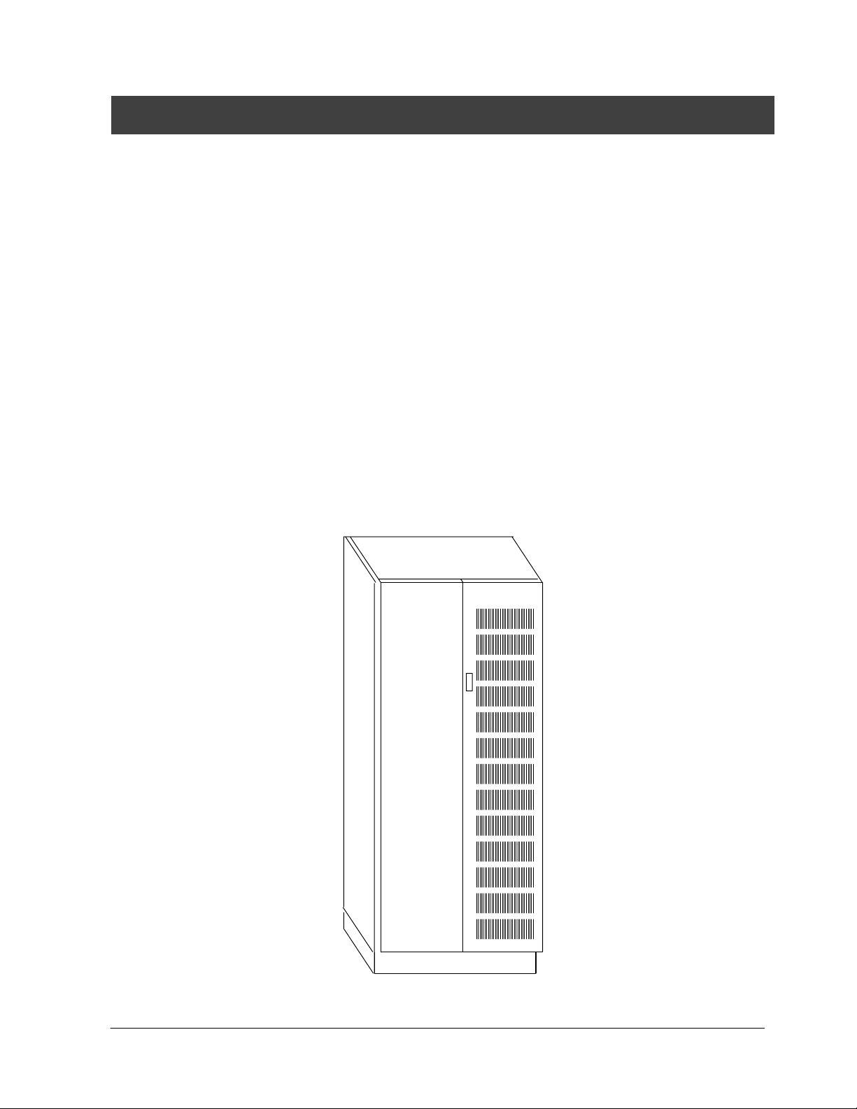
The parallel cabinet is a free-standing cabinet. Figure 1 shows a typical parallel
cabinet.
Figure 1. Typical Parallel Cabinet
Powerware 9315 Parallel Redundant System I & O
164202013 Rev. D 041599
1
Page 8

Using This Manual
This manual contains installation and operation procedures for the PowerwareÒ
9315 Parallel Redundant system. In this manual, parallel redundant system refers
to the parallel cabinet, its internal components, and those components of the UPS
modules that assist in parallel redundant operation. The text uses these
conventions:
· Bold type highlights important concepts in discussions, key terms in
procedures, and menu options.
· Italic type highlights notes, references to other system manuals, references to
other sections of this manual, and new terms where they are defined.
· Rectangular boxes containing bold type are warnings or cautions that pertain to
the parallel redundant system or its electrical connections. This important
information indicates possible dangers pertaining to personnel safety,
equipment damage, critical load protection, or operational concerns.
Before installation of the parallel redundant system, read through each installation
procedure provided in Section 1 Installation of this manual. Below is a description
of each chapter in each section as they appear:
Section 1
· Chapter 1 tells you how to prepare the site for the installation of the parallel
cabinet. It discusses equipment environmental requirements, inspecting and
unpacking the parallel cabinet, and pallet removal.
· Chapter 2 describes how to install the parallel cabinet.
· Chapter 3 describes parallel redundant configurations of UPS modules utilizing
separate battery cabinets or sharing a common battery cabinet.
Section 2
· Chapter 4 describes the parallel redundant system and its operation.
· Chapter 5 provides information on understanding parallel operation.
· Chapter 6 contains operation instructions for the parallel redundant system.
· Appendix A contains important information on wiring requirements and
recommendations, and important diagrams of the cabinet’s mechanical details
and electrical access.
Read through each procedure before you begin. Perform only those procedures
that apply to the UPS system you are installing.
2
Powerware 9315 Parallel Redundant System I & O
164202013, Rev. D 041599
Page 9

For More Information
This manual describes the installation and operation of the parallel redundant
system. For more information on the installation and operation of the UPS system
and its accessories, refer to the following:
164200252 Powerware
9315 30---160 kVA UPS Operation
164201036 Powerware
164201119 Powerware
Each manual describes the UPS cabinet Control Panel and
Monitor Panel, and explains the functions of the UPS; discusses
the standard features o f the UPS and optional accessories;
provides procedures for starting and stopping the UPS, and
information about maintenance and responding to system events.
A l s o d e s c r i b ed a r e t h e R S --- 48 5 a n d R S --- 2 3 2 s e r ia l
communications capabilities of the UPS system; discusses the
two communications ports on the Customer Interface Panel
inside the UPS and how to connect optional remote accessories
to your UPS system; provides information about enabling,
disabling, and customizing building alarms.
164200253 Powerware
164200292 Powerware
164201037 Powerware
164201118 Powerware
Each manual contains the following information: how to prepare
the site and plan for installation, detailed step-by-step
procedures for installing each component of your system, how to
join cabinets in a line-up-and-match system, detailed illustrations
of cabinets and optional accessories, including dimensions and
connection points.
9315 200---300 kVA UPS Operation
9315 400/500 (300--- 500 kVA) UPS Operation
9315 30---80 kVA UPS Installation
9315 100---160 kVA UPS Installation
9315 200---300 kVA UPS Installation
9315 400/500 (300---500 kVA) UPS Installation
Contact the local Powerware Field Service office for information on how to obtain
copies of these manuals.
Getting Help
If you have a question about any of the information in this manual, or if you have a
question this manual does not answer, please call Powerware Corporation Field
Service:
United States 1-800-843-9433
Canada 1-800-461-9166
Outside the U.S. Call your local representative
Powerware 9315 Parallel Redundant System I & O
164202013 Rev. D 041599
3
Page 10

This Page Intentionally Left Blank.
4
Powerware 9315 Parallel Redundant System I & O
164202013, Rev. D 041599
Page 11

Section I
Installation
Powerware 9315 Parallel Redundant System I & O
164202013 Rev. D 041599
5
Page 12

This Page Intentionally Left Blank.
6
Powerware 9315 Parallel Redundant System I & O
164202013, Rev. D 041599
Page 13
Getting Started
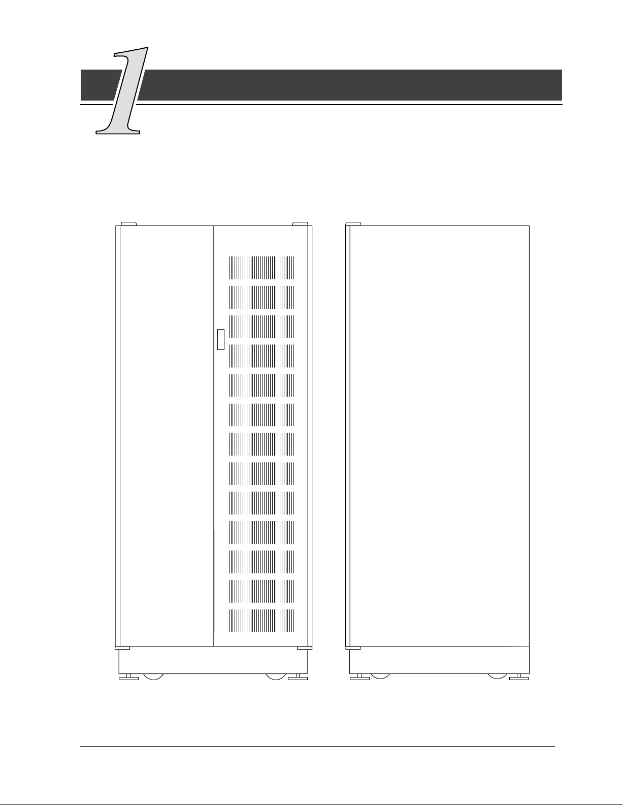
This section describes how to install the parallel cabinet. It contains only
instructions for installing the parallel cabinet as a remote cabinet,
configuration needed for parallel redundant operation, and basic site preparation
procedures. Figure 2 shows the front and side view of the parallel cabinet.
Figure 2. Front and Side View of Parallel Cabinet
Powerware 9315 Parallel Redundant System I & O
164202013 Rev. D 041599
7
Page 14

The parallel cabinet is shipped on a separate pallet. Use a forklift or pallet jack to
move the packaged cabinet to the installation site, or as close as possible to the
site, before unloading from the pallet.
The basic sequence of the installation steps is:
1. Prepare the site for the cabinet installation.
2. Inspect, unpack, and unload the cabinet.
3. Create an installation plan for wiring the parallel cabinet to the corresponding
UPS modules.
4. Prepare for wiring.
5. Complete the installation checklist from the PowerwareR 9315 Installation manual.
6. Have authorized service personnel perform preliminary checks and startup.
NOTE: Startup and operational checks should be performed only by authorized
service personnel. This service is usually offered as part of the sales
contract for your UPS system.
Preparing the Site
For the parallel redundant system to operate at peak efficiency, the installation site
should meet the environmental parameters outlined in the PowerwareÒ 9315
Operation manual provided with the UPS system. The operating environment must
meet the size and weight requirements supplied in the PowerwareÒ 9315
Installation manual provided with the UPS system. If the parallel redundant system
is to be operated at an altitude higher than 1500 meters (5000 feet), contact the
local sales or service office for important information about high altitude operation.
The basic environmental requirements for operation of the parallel redundant
system are:
Ambient Temperature Range: 0 --- 4 0 ˚C (32---104˚F)
Recommended Operating Range: 20 --- 25˚C (68 --- 77˚F)
Maximum Relative Humidity: 95%
The parallel cabinet uses convection cooling to regulate internal component
temperature. Air inlets are in the front of the cabinet, and outlets are in the top.
Clearance in front of and above each cabinet for proper air circulation is essential.
8
Powerware 9315 Parallel Redundant System I & O
164202013, Rev. D 041599
Page 15

Environment Considerations
Thelifeoftheparallelredundantsystemwillbeadverselyaffectediftheinstallation
does not meet the following guidelines:
1. The parallel cabinet must be installed on a sealed concrete pad on a sealed
concrete floor.
2. The parallel cabinet must be installed in a dust-free environment.
3. The parallel cabinet must be installed in a humidity-controlled environment.
Preparing for Wiring the Parallel Redundant System
See Tables A---1 through A---4 in Appendix A of this manual for wiring requirements.
The power wiring for this equipment is rated at 75_C. Ifwireisruninanambient
temperature greater than 30_C, higher temperature and/or larger size wire may be
necessary. Wiring for the paralle cabinet should be installed through the 28.6 mm
(1.1 in.) knockout in the bottom of the UPS cabinet. The top entry connection
requires installation of 1/2-in. flexible conduit within the UPS. Bottom entry
connection requires no additional routing of conduit within the UPS. For UPS
external wiring requirements, including minimum AWG size of external wiring, see
the PowerwareÒ 9315 Installation manual provided with the UPS system.
NOTE: Material and labor for external wiring are to be provided by designated
personnel.
Powerware 9315 Parallel Redundant System I & O
164202013 Rev. D 041599
9
Page 16
Inspecting and Unpacking the Parallel Cabinet
The first task in preparing for installation of the parallel cabinet is inspecting and
unpacking the cabinet. The cabinet arrives covered with protective packaging
material as shown in Figure 3.
OUTER
PACKA GING
10
FOAM CUSHION
Figure 3. Cabinet as Shipped, with Outer Packaging and Pallet
1. Carefully inspect the outer packaging for evidence of damage during transit.
CAUTION:
Do not install a damaged cabinet. Report any damage to the carrier and
contact the local sales or service office immediately.
2. Use a forklift or other material handling equipment to move the cabinet to a
convenient unpacking area. Insert the forklift jacks between the foam cushions
on the bottom of the unit.
CAUTION:
Do not tilt cabinet more than 10 degrees from vertical.
Powerware 9315 Parallel Redundant System I & O
164202013, Rev. D 041599
Page 17

3. Set the pallet on a firm, level surface, allowing a minimum clearance of
4.6m (15 ft) on each side for removing the cabinet from the pallet.
4. Cut the steel bands around the cabinet.
5. Remove the protective cardboard covering from the cabinet, cutting where
indicated, using a knife blade no longer than 25 mm (1 in.).
NOTE: Do not discard the packaging material yet. Instructions for unloading the
cabinet from the pallet are printed on the cardboard, and you will need to
refer to them.
6. Remove the plastic bag and foam packing material, and discard or recycle
them in a responsible manner.
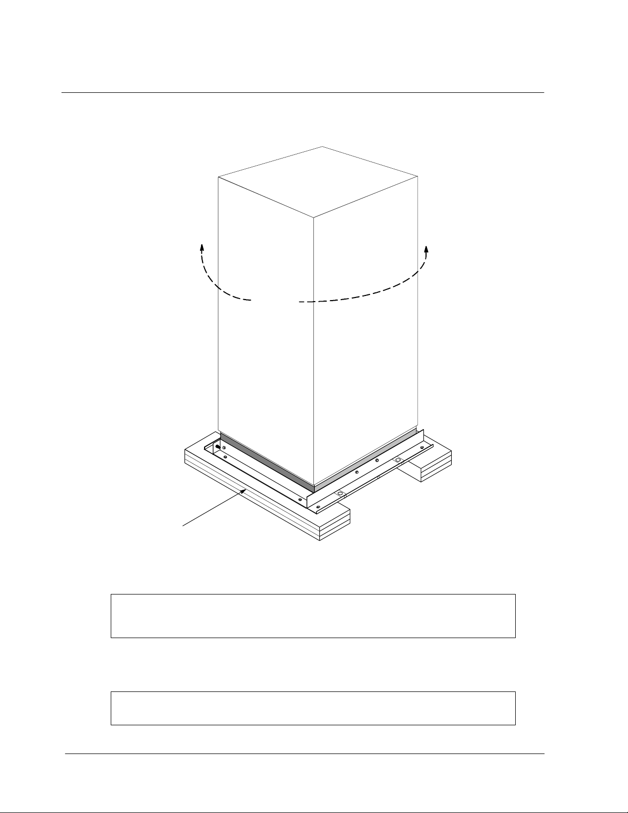
Unloading the Parallel Cabinet From the Pallet
The parallel cabinet consists of four supports secured to foam cushions. The foam
cushions act as shock absorbers for the cabinet during shipment.
WARNING:
Cabinet is extremely heavy. If unloading instructions are not closely
followed, the cabinet may tip and cause serious injury.
Turning the jacking bolts unevenly may cause the cabinet to become
unbalanced. To prevent tipping, raise and lower the jacking bolts
evenly. The cabinet should only be raised approximately 3 mm (
above the floor (just enough to remove foam cushions).
1/8 in.)
1. Remove the doors. Remove the retaining screw located inside each door at
the bottom hinge pivot point, then lift the door off. Save the retaining screws
for reinstallation of the doors.
2. Locate the field kit (packed inside of the cabinet or communication panel).
Locate the four ½-in. jacking bolts and install them in the threaded holes in the
front and rear supports. Place a floor protector underneath each jacking bolt,
and screw the bolts down against them. The floor protectors will save the floor
from being marred by the jacking bolts.
3. Loosen, but do not remove the hardware holding the foam cushions to the
front and rear supports (labeled “1” in Figure 4).
4. Turn each jacking bolt consecutively, two full turns, until the foam cushions
clear the floor by approximately 3 mm (
1/8 in.).
5. After the foam cushions clear the floor, remove the hardware loosened in
step 3. Pull the foam cushions out from under the cabinet, and discard or
recycle them in a responsible manner.
Powerware 9315 Parallel Redundant System I & O
164202013 Rev. D 041599
11
Page 18

DOOR
1
FLOOR
PROTECTOR
2
FRONT
SUPPORT
SIDE
SUPPORT
FOAM
CUSHION
2
2
JACKING
BOLT
Figure 4. Removing Front and Rear Supports
2
1
1
WARNING:
Cabinet may fall. Do not loosen hardware attaching the side or front
supports to the cabinet base. Also, do not loosen supports from each
other. The cabinet must be lowered using jacking bolts before supports
can be removed.
6. Carefully and evenly lower the cabinet by turning each jacking bolt
consecutively two full turns (maximum)
the cabinet is no longer supported by the jacking bolts.
until the supports contact the floor, and
7. After the cabinet is resting on the floor, remove the jacking bolts and discard or
recycle them in a responsible manner.
12
8. Removethehardwarelabeled“2”inFigure4,holdingthefront,rearandside
supports to the cabinet base. Discard or recycle the hardware and support
brackets in a responsible manner.
9. Install the doors removed in step 1. The parallel cabinet is now ready to be
rolled to its final location.
Powerware 9315 Parallel Redundant System I & O
164202013, Rev. D 041599
Page 19

Creating an Installation Plan
Before beginning to install the parallel cabinet, read and understand how this
manual applies to the system being installed. It is important to note that UPS
module installation procedures are contained in the PowerwareÒ 9315 Installation
manual provided with the UPS system. It is recommended to first understand how
to install the UPS modules. The information in Chapter 2 of this manual is a guide
in installation of the parallel cabinet to the UPS modules.
Powerware 9315 Parallel Redundant System I & O
164202013 Rev. D 041599
13
Page 20

This Page Intentionally Left Blank.
14
Powerware 9315 Parallel Redundant System I & O
164202013, Rev. D 041599
Page 21

Installing the Parallel
Redundant System
Once the parallel cabinet has been moved to its installed location, unpacked, and
inspected, it is ready for installation. This manual discusses the typical
configuration of installing the parallel cabinet in a remote location. The parallel
cabinet arrives as shown in Figure 5.
Cooling Air Inlets
Cooling Grate
Top
(Cooling Air Outlets)
Wire
Entry
Cable Entry, Top View
Bottom Wire Entry
Cable Entry, Floor Plan View
Figure 5. Top, Bottom, and Front View of Parallel Cabinet
Powerware 9315 Parallel Redundant System I & O
164202013 Rev. D 041599
15
Page 22

Refer to the following while installing the parallel cabinet:
· Dimensions in this manual are in millimeters and inches.
· Do not tilt the cabinet more than 10˚ during installation.
· The conduit landing plates are to be removed to add conduit landing holes as
required. Plate material is 16 gauge steel (0.06 in. thick).
· Terminals E9–E12 and E16 ---E18 are UL and CSA rated at 90˚C. Ahexkeytool
is required to attach wires to the terminals.
· Details about control wiring are provided in Table A---1 of Appendix A and the
Control Wiring Interconnect Details in Chapter 3 of this manual.
Figure 6 shows typical control wiring and power wiring terminations of the UPS
module and parallel cabinet. Refer to the Powerware 9315 Installation manual
provided with the UPS system for location of UPS module cabinet wiring
terminations.
NOTE: Material and labor for external wiring are to be provided by designated
personnel.
MOB#1 TB1
MOB#2
TB1
Output
Neutral
Connection
(E12)
A/C Output
E9, E10,
E11
E10
E10
E11
E9
E9
MOB1
MOB2
LEFT DOOR
TB1
TB3
Terminal Strip
UPS MODULE
TB2
Communication Panel
(100--160kVA UPS Shown)
ÆA ÆCÆBÆA ÆC
E16 E17 E18
Ground
PARALLEL CABINET
ÆB
Figure 6. Typical Control and Power Wiring Terminations of UPS Module
and Parallel Cabinet
E11
E12
Isolated
Ground
(Optional)
16
Powerware 9315 Parallel Redundant System I & O
164202013, Rev. D 041599
Page 23

Parallel Redundant Modules
with Separate Batteries
and Common Batteries
This chapter describes the internal connections of the parallel cabinet to UPS
modules utilizing separate battery cabinet(s) and a shared battery cabinet(s).
Determine which battery configuration is being utilized before beginning
installation. If battery cabinets and remote disconnects provided by Powerware
Corporation are being installed, refer to the Powerware Series 685 and 1085
Auxiliary Battery Cabinets Installation manual, 164200300, for instructions on
installation. If battery cabinets not provided by Powerware Corporation are being
installed, refer to the battery cabinet manufacturer’s manual for instructions on
battery cabinet installation and maintenance.
Powerware 9315 Parallel Redundant System I & O
164202013 Rev. D 041599
17
Page 24

Parallel Redundant Modules with Separate Batteries
There are two possible configurations for battery connection of the parallel
redundant system. The two UPS modules may share the same battery cabinet(s),
or each module may use a separate battery cabinet(s). Figure 7 shows a diagram
of the parallel redundant system with UPS modules utilizing separate battery
cabinets.
NOTE: Refer to Powerware 9315 Installation manual provided with the UPS system
for battery shunt trip connections.
C C
Battery
Cabinet
UPS
Module 1
TB3 TB3
Battery
Cabinet
UPS
Module 2
BA BA
MOB #1
TB1
MOB1 MOB2
UPS #1
Input
E9---E12
Parallel Cabinet
Critical
Output Bus
E16---E18
UPS #2
Input
E9---E12
Figure 7. Modules with Separate Batteries
MOB #2
TB1
18
Powerware 9315 Parallel Redundant System I & O
164202013, Rev. D 041599
Page 25

Figure 7 points out the connection areas of the two UPS modules and the parallel
cabinet. The A connection is the power input connections from UPS 1 and UPS 2 to
the parallel cabinet. It is recommended that the UPS modules are labeled in
accordance with Module Output Breaker (MOB) labeling (e.g., the MOB 1 terminals E9
through E11 should be wired with UPS 1 terminals E9 through E11, E12 is the
neutral). The MOBs have already been designated as MOB 1 and MOB 2. See
Table A- -- 2 in Appendix A of this manual for power terminations of the parallel cabinet
and the UPS modules. For power wiring requirements and recommendations, see
Tables A-- -3 and A---4 in Appendix A of this manual. For power wiring connections or
terminal strip locations, refer to Figure 13 in Appendix A of this manual.
The B connection is the control wiring connection between the communication panels
of the UPS modules and the parallel cabinet. In the UPS module, the TB3 terminal
strip is located on the left side of the UPS cabinet and to the left of the TB1 terminal
strip on its communication panel. For control wiring requirements and
recommendations, see Table A -- -1 in Appendix A in this manual. For control wiring
connections and terminal strip locations, refer to Figure 13 in Appendix A of this
manual.
For the UPS Module connections, please refer to the PowerwareÒ 9315 Installation
manual provided with the UPS system for protection and wiring requirements and
recommendations.
For the C connections, make sure the bypass feeds originate from the same power
source. Means for separate isolation (circuit breaker or disconnect) are
recommended. Refer to the PowerwareÒ 9315 Installation manual provided with the
UPS system for bypass power wiring.
Powerware 9315 Parallel Redundant System I & O
164202013 Rev. D 041599
19
Page 26

Parallel Redundant Modules with Common Battery
Figure 8 is a diagram of the parallel redundant system containing UPS modules
sharing a common battery cabinet.
NOTE: UPS modules sharing a battery cabinet(s) must utilize a remote battery
cabinet(s). Refer to the Powerware Series 685 and 1085 Auxiliary Battery
Cabinets Installation manual 164200300, for instructions on installation.
Refer to Powerware 9315 Installation manual provided with the UPS System
for battery breaker shunt trip connections.
C C
TB3
DD
UPS
Module 1
Battery
Cabinet
UPS
Module 2
BA BA
MOB #1
TB1
UPS #1
Input
E9---E12
UPS #2
Input
E9---E12
TB3
MOB #2
TB1
20
MOB1 MOB2
Parallel Cabinet
Critical
Output Bus
E16---E18
Figure 8. Modules with Common Battery
Powerware 9315 Parallel Redundant System I & O
164202013, Rev. D 041599
Page 27

Figure 8 points out the connection areas of the two UPS modules and the parallel
cabinet. The A connection is the power input connections from UPS 1 and UPS 2 to
the parallel cabinet. It is recommended that the UPS modules are labeled in
accordance with Module Output Breaker (MOB) labeling (e.g., the MOB 1 terminals E9
through E11 should be wired with UPS 1, terminals E9 through E11, E12 is the
neutral). The MOBs have already been designated as MOB 1 and MOB 2. See
Table A- -- 2 in Appendix A of this manual for power terminations of the parallel cabinet
and the UPS modules. For power wiring requirements and recommendations, see
Tables A-- -3 and A---4 in Appendix A of this manual. For power wiring connections or
terminal strip locations, refer to Figure 13 in Appendix A of this manual.
The B connection is the control wiring connection between the communication panels
of the UPS modules and the parallel cabinet. In the UPS module, the TB3 terminal
strip is located on the left side of the UPS cabinet and to the left of the TB1 terminal
strip on its communication panel. For control wiring requirements and
recommendations, see Table A -- -1 in Appendix A in this manual. For control wiring
connections and terminal strip locations, refer to Figure 13 in Appendix A of this
manual.
For the UPS Module connections, please refer to the PowerwareÒ 9315 Installation
manual provided with the UPS system for protection and wiring requirements and
recommendations.
For the C connections, make sure the bypass feeds originate from the same power
source. Means for separate isolation (circuit breaker or disconnect) are
recommended. Refer to the PowerwareÒ 9315 Installation manual provided with the
UPS system for bypass power wiring.
For the D connection, make sure input feeds originate from the same power source.
Means for separate isolation (circuit breaker or disconnect) are recommended. Refer
to the PowerwareÒ 9315 Installation manual provided with the UPS system for input
feeds to the UPS module.
Powerware 9315 Parallel Redundant System I & O
164202013 Rev. D 041599
21
Page 28

Power Wiring Details
Each UPS module must be wired to its corresponding module output breaker in the
cabinet with power cables sufficient for carrying the load. Recommended wiring
size is listed in Tables A---3 and A--- 4 of Appendix A of this manual. Each of the
three phases plus the neutral must be wired. Nonlinear loads can create neutral
currents that are greater than 100%. The neutral bus (terminal strip E12) contains
sufficient cable landing to wire double-size neutrals if needed.
NOTE: Material and labor for external wiring are to be provided by designated
personnel.
22
Powerware 9315 Parallel Redundant System I & O
164202013, Rev. D 041599
Page 29

Control Wiring Interconnect Details
Each UPS module requires control signal wiring from the module to the parallel
cabinet. The purpose of signaling is to facilitate the closing of the module output
breakers and coordinate transfers to and from bypass. Once this system has been
properly placed into operation, it will operate as a parallel redundant system even if
the control wiring becomes disabled through shorts or opens. Figure 9 shows the
grouping for twisting requirements. Refer to Table A in this chapter for control
wiring recommendations and termination capability.
NOTE: Material and labor for external wiring are to be provided by designated
personnel.
Table A. Control Wiring Requirements and Termination Requirements
Connection
Points in
Parallel
Cabinet
TB1--1
through
TB1--7
Size of
Pressure
Termination
(lb--in)
#18--#8,
(55)
Maximum
Voltage and
Current
24V, 0.25A TB3--1 through
Connection
Points in UPS
TB3--7
Size of
Pressure
Termination
(lb--in)
#22--#12,
(5--7)
Recommended
Wiring Size
#18--#12
Notes for Table A:
1. Install the control wiring in separate conduit from the power wiring. Only
copper wire or tinned copper wire should be used.
2. Control wiring is NEC class 2 (IEC 950 SELV).
3. Class 1 methods are recommended for control wiring.
4. Control wiring should be twisted pairs and twisted triple as shown in Figure 9.
1
2
3
4
5
6
7
Parallel
Cabinet
MOB#1
(#2)
UPS
Module 1
(or 2)
TB3 TB1
1
2
3
4
5
6
7
Indicates grouping for twisting requirements.
Figure 9. Grouping for Twisting Requirements
Powerware 9315 Parallel Redundant System I & O
164202013 Rev. D 041599
23
Page 30

This Page Intentionally Left Blank.
24
Powerware 9315 Parallel Redundant System I & O
164202013, Rev. D 041599
Page 31

Section II
Operation
Powerware 9315 Parallel Redundant System I & O
164202013 Rev. D 041599
25
Page 32

This Page Intentionally Left Blank.
26
Powerware 9315 Parallel Redundant System I & O
164202013, Rev. D 041599
Page 33

Getting Started
The PowerwareÒ 9315 Uninterruptible Power Supply (UPS) continually
monitors incoming electrical power and removes the surges, spikes, sags, and
other irregularities that are inherent in commercial utility power. With the
PowerwareÒ 9315 Parallel Redundant system, when one UPS module is taken off
line or becomes disabled, the redundant module continues working with the
building’s electrical system to supply clean, consistent power that sensitive
electronic equipment requires for reliable operation.
The parallel redundant system should function automatically and require very little
attention during normal operation. However, once installation has been completed,
read and understand the procedures in this section as they are provided to ensure
trouble-free operation.
Each component of the parallel redundant system is housed in a free-standing
cabinet designed for industrial or computer room applications. The parallel cabinet
has safety shields behind the doors for hazardous voltage protection.
The following descriptions provide a brief overview of the standard parallel
redundant features.
NOTE: Read the Operation section and have thorough knowledge of parallel
redundant operation before attempting to operate. For a more detailed
description of UPS operation, refer to PowerwareÒ 9315 Operation manual
supplied with the UPS system.
Powerware 9315 Parallel Redundant System I & O
164202013 Rev. D 041599
27
Page 34

Parallel Redundant System Description
The parallel redundant system consists of two identical UPS modules, a parallel
cabinet, and one or two battery racks or cabinets.
The parallel cabinet consists of two module output breakers designated MOB 1
and MOB 2. These output breakers receive power input from the AC output of the
UPS modules. If one UPS module becomes disabled, it trips off, leaving the
redundant UPS module to continue to supply power to the critical load. The
primary function of the MOBs is to allow isolation of a module for maintenance or
service. In a parallel redundant system the redundant module becomes the
system’s maintenance bypass source.
There are two lamps located on the inside of the parallel cabinet labeled
OK TO CLOSE. When one of these lamps illuminates, the corresponding MOB
canbeclosed. ItisimportanttonotethatitisonlysafetoclosetheMOBswhen
the OK TO CLOSE indicator lights are illuminated. A LAMP TEST pushbutton is
located inside the parallel cabinet for testing these indicators. The parallel cabinet
also includes associated terminal strips for making the power and control
connections to UPS modules. Figure 10 shows the controls and indicators of the
parallel cabinet.
28
Powerware 9315 Parallel Redundant System I & O
164202013, Rev. D 041599
Page 35

MODULE
OUTPUT
BREAKER 1
(MOB 1)
MODULE
OUTPUT
BREAKER 2
(MOB 2)
Figure 10. Controls and Indicators
Powerware 9315 Parallel Redundant System I & O
164202013 Rev. D 041599
29
Page 36

Looking Inside the Parallel Redundant System
The parallel redundant system supports the normal operation of the PowerwareÒ
9315 UPS system by offering parallel redundant capability. The UPS system
continues to maintain power to the critical loads during commercial electrical power
brownout, blackout, overvoltage, undervoltage, and out-of-tolerance frequency
conditions. The parallel redundant system ties two UPS modules together, in
parallel, in order for continuous power to flow even when one module becomes
disabled. Refer to Figure 13 in Appendix A of this manual for the detailed
relationship of the parallel cabinet and the UPS modules.
If utility power is interrupted or falls outside the parameters specified in the
PowerwareÒ 9315 Operation manual, the UPS system uses a backup battery
supply to sustain power to the critical load for a specified period of time or until the
utility power returns. For extended power outages, the backup battery supply
allows you to either transfer to an alternate power system (such as a generator) or
shut down the critical load in an orderly manner. Refer to the PowerwareÒ 9315
Operation manual provided with the UPS system for operation of the UPS.
30
Powerware 9315 Parallel Redundant System I & O
164202013, Rev. D 041599
Page 37

Safety Considerations
The UPS cabinet and parallel cabinet enclosures are designed for industrial or
computer room applications, and contain safety shields behind the doors.
However, the parallel redundant system is a sophisticated power system and
should be handled with appropriate care, following these guidelines:
· Keep surroundings clean and free from excess moisture.
· Do not operate the parallel redundant system close to gas or electric heat
sources.
· The system is not intended for outdoor use.
· The operating environment should be maintained within the parameters
stated in this manual and the Powerware 9315 Operation manual provided
with the UPS system.
· Keep the cabinet doors closed to ensure proper cooling airflow and to
protect personnel from dangerous voltages inside the unit.
· The parallel redundant system contains its own power source. Lethal
voltages are present even when the UPS is disconnected from utility
power.
WARNING:
Only AUTHORIZED SERVICE PERSONNEL should perform service or
maintenance on the parallel redundant system.
If service or routine maintenance is required:
· Ensure all power is disconnected before performing installation or service.
· Ensure the area around the parallel redundant system is clean and
uncluttered.
· Battery cabinet maintenance or battery replacement should be performed
only by authorized service personnel.
· Observe all DANGER, CAUTION, and WARNING notices affixed to the
inside and outside of the equipment.
· Refer to the more detailed safety precautions described in the Powerware
9315 Operation manual provided with the UPS system.
Powerware 9315 Parallel Redundant System I & O
164202013 Rev. D 041599
31
Page 38

Symbols, Controls, and Indicators
These symbols may appear on the parallel redundant system or on labels inside
the UPS or parallel cabinet. They are accepted by most international safety agents.
Everyone who works with the parallel redundant system should understand the
meaning of these symbols:
ON
The principal power switch is in the “On” position.
OFF
The principal power switch is in the “Off” position.
PHASE
The word “phase.”
CAUTION: REFER TO MANUAL
Stop and refer to the Operator’s Manual for more information.
RISK OF ELECTRIC SHOCK
There is a risk of electric shock present, and you should observe
associated warnings. The equipment contains high voltages.
32
Powerware 9315 Parallel Redundant System I & O
164202013, Rev. D 041599
Page 39

Understanding Parallel
Redundant Operation
With the parallel redundant system, the UPS system continues to function
automatically to supply AC electrical power to the critical load. There are three
operation modes in this system:
· In Normal mode, the UPS system functions normally as described in the
PowerwareR 9315 Operation manual provided with the UPS system. In the
parallel redundant system, power leaves the UPS module from its AC output
and is routed into the designated MOB in the parallel cabinet. As the system is
in Normal mode, the MOBs are closed and clean power is routed directly to the
AC output of the parallel cabinet and then to supply the critical load.
· In Battery mode, the battery cabinet supplies DC power, which maintains UPS
operation. The battery supports the critical load through the parallel cabinet’s
AC output.
· In Bypass mode, interunit signaling is used by each UPS to determine if its
designated MOB is closed and if the redundant module is on bypass or normal.
This information causes differences to the usual bypass operation of the UPS
system.
The following description provides the operating mode differences between the
parallel redundant and single UPS module systems.
Powerware 9315 Parallel Redundant System I & O
164202013 Rev. D 041599
33
Page 40

Normal, Battery, and Bypass Modes with Parallel Operation
With the parallel redundant system, there are operating mode differences. These
differences primarily deal with the way transfers to and from bypass are handled.
When both UPS modules are in Normal mode, the parallel redundant system
functions normally to supply clean, filtered power to the critical load. The AC
output of the UPS modules feed the clean power to its designated MOB in the
parallel cabinet. In Normal mode, the MOBs are closed and power continues to
the AC output (critical bus) of the parallel cabinet, supporting the critical load.
Whenthereisapoweroutageorsomedisturbanceintheutility,theUPSmodules
automatically switch to Battery mode. In Battery mode, the battery supplies power
to the critical load as in normal UPS system operation. The only difference is that
the critical bus in the parallel cabinet is the AC output. See the PowerwareÒ 9315
Operation manual provided with the UPS system for details on Battery mode of
operation.
When both UPS modules are in Bypass mode, utility power directly supports the
critical load as is normal in UPS system operation.
When one UPS module becomes disabled and the redundant module is in Normal
mode, the disabled module shuts off rather than transfer to Bypass. The redundant
module continues to supply power to the critical load. Bypass is only activated if
the critical bus in the parallel cabinet fails to recover within a quarter cycle of the
initial disturbance.
If a manual transfer to Bypass mode is initiated while the redundant module is in
Normal mode, the module to be transferred to Bypass simply shuts off.
If both UPS modules are in bypass and their mode switches are in the Normal
mode position, activate the key switch on either UPS module and both modules
transfer to Normal.
If one UPS module is in Normal mode and the redundant module is in Bypass
mode, the following sequence will take place:
· The module in Bypass will automatically try to transfer to Normal mode
· If unable to transfer to Normal mode, the redundant module will try to
automatically clear itself from Bypass
· If the redundant module is unable to clear itself from Bypass, the module in
Normal mode will wait ten (10) seconds and then transfer to Bypass.
34
Powerware 9315 Parallel Redundant System I & O
164202013, Rev. D 041599
Page 41

Operating Instructions for
the Parallel Redundant System
The following procedures are for the operation of UPS modules in parallel. After
installation of the parallel redundant system, the UPS modules run in parallel with
each other.
Module Output Breakers (MOBs)
The parallel cabinet contains two MOBs labeled MOB 1 and MOB 2. The UPS
modules should be labeled in accordance with which MOB it is connected (e.g.,
MOB 1 should be wired to UPS 1).
When both MOB 1 and MOB 2 are closed, each UPS module operates as part of a
parallel system. When one MOB is open, the redundant UPS module continues to
support the critical load. The redundant UPS module acts as a single stand-alone
system.
How to Open and Close the MOB
CAUTION:
Improper operation of these circuit breakers can cause the loss of the critical
bus (output) or damage equipment.
Close the MOB only when its designated OK TO CLOSE lamp is illuminated.
A UPS module’s designated MOB, MOB 1 or MOB 2, may be opened if the MOB
for the redundant module is closed and its OK TO CLOSE lamp is illuminated.
Refer to How to Isolate a Module in this chapter for information on when a module’s
designated MOB can be opened.
Starting and Stopping Using Parallel Redundant System
Start each module as described for normal UPS system startup in the PowerwareÒ
9315 Operation manual provided with the UPS system. If the MOBs have been
opened, they should only be closed when the OK TO CLOSE lamp is illuminated.
The following descriptions give details on starting in modes, turning the module off,
and using the LOAD OFF pushbutton.
Powerware 9315 Parallel Redundant System I & O
164202013 Rev. D 041599
35
Page 42

How to Isolate a Module
The primary function of the MOBs is to allow isolation of a module for maintenance
or service. In parallel operation, each module becomes the other’s maintenance
bypass source.
Do not attempt to isolate a module until it is assured that the redundant module
can support the critical load. The best assurance is if the redundant UPS module’s
designated MOB is closed and the OK TO CLOSE lamp is illuminated.
As an alternative:
1. Make sure the designated MOB for both modules is closed.
2. PlacetheUPSmoduletobeisolatedinBypassmode.
3. Place the redundant module in Bypass mode.
4. Open the designated MOB of the UPS module to be isolated.
When a module’s designated MOB is open, it will work like a standard Reverse
Transfer module as described in the PowerwareÒ 9315 Operation manual provided
with the UPS system. The MOB should only be closed when its OK TO CLOSE
lamp is illuminated.
Shut Down a Module
To turn a module off, place its mode switch to the Bypass position and open its
circuit breaker (CB1).
Transfer System to Bypass
To place the system in Bypass mode:
1. TurnthemodeswitchonbothUPSmodulestotheBypassposition. Thefirst
module will shut off its inverter and the redundant module will transfer to
Bypass.
To place both UPS modules on Bypass:
1. TurnthemodeswitchonbothUPSmodulestotheBypassposition.
2. After the first module shuts off and the redundant module is in Bypass, activate
the start switch on the first module with the mode switch still in the Bypass
position.
To transfer both UPS modules from Bypass mode to Normal mode:
1. Turn the mode switch on both modules to the Normal position.
36
2. Activate the start switch on either UPS module.
Powerware 9315 Parallel Redundant System I & O
164202013, Rev. D 041599
Page 43

LOAD OFF
The LOAD OFF pushbutton (referred to as the emergency power off) only
interrupts the ability of a single module to deliver power to the critical bus. The
redundant module will continue to support the critical load. Refer to the Powerware
9315 Operation manual for details on the LOAD OFF pushbutton.
NOTE: The LOAD OFF pushbutton will only interrupt the ability for that module to
deliver power to the critical bus. The LOAD OFF pushbutton must be
pressed on both UPS modules in order to cut off power from the critical
load. For a single emergency power off switch, a switch should be
connected to both modules. Each module should be wired from an isolated
contactofthatswitch.
Powerware 9315 Parallel Redundant System I & O
164202013 Rev. D 041599
37
Page 44

This Page Intentionally Left Blank.
38
Powerware 9315 Parallel Redundant System I & O
164202013, Rev. D 041599
Page 45

Appendix A
The information in Appendix A will help plan for and install the parallel redundant
system. The appendix contains the following figures and tables:
· Figure 11 UPS Outputs and Communications
· Figure 12 Mechanical Details
· Figure 13 Electrical Access Details
· Table A---1 Control Wiring Requirements and Termination Requirements
· Table A---2 UPS Power Cable Terminations and Connection Points
· Table A---3 Tie Cabinet Power Inputs and Termination Requirements
· Table A---4 Power Output Termination Requirements
Powerware 9315 Parallel Redundant System I & O
164202013 Rev. D 041599
A---1
Page 46

LEFT SIDE PANEL
OUTPUT
NEUTRAL
CONNECTION
(E12)
AC OUTPUT
(E9, E10, E11)
TB3
TERMINAL STRIP
LEFT DOOR
TB1
TB3
COMMUNICATION
TB2
RIGHT SIDE PANEL
SIDE PANEL
MOUNTING SCREWS
LEVELING FEET
PANEL
A --- 2
NOTE: 100---160 KVA UPS Shown with Right Door Open or Removed
Figure 11. UPS Outputs and Communications
Powerware 9315 Parallel Redundant System I & O
164202013, Rev. D 041599
Page 47

1870.0
(73.6)
853.8
(33.6)
800.0
(31.5)
FRONT VIEW
Dimensions are in millimeters (inches)
Cabinet Weight: 260 kg (570 lb)
Cooling Requirements: Convection
Heat Rejection: Nil
Powerware 9315 Parallel Redundant System I & O
164202013 Rev. D 041599
PARALLEL TIE CABINET
SIDE VIEW
Figure 12. Mechanical Details
A---3
Page 48

E9
E10
E11
E9
853.8
(33.6)
E10
E11
MOB#1
TB1
MOB#2
TB1
339.85
(13.38)
853.8
(33.6)
Cooling Grate
Top
Wire
Entry
1 15.32
(4.54)
800.0
(31.5)
1870.0
(73.6)
MOB1
MOB2
ÆA ÆCÆBÆA ÆC
E16 E17 E18
Ground
ÆB
E12
Parallel Cabinet
Terminal Locations
Wire Way
Isolated
Ground
(Optional)
122.70
(4.83)
560.63
(22.07)
Parallel Cabinet Cable Entry,
Top Vie w
88.90 (3.50)
Swivel Radius
100.08
(3.94)
606.30
(23.88)
545.42
(21.5)
518.92
(20.43)
Bottom Wire Entry
142.40
(5.61)
50.04
(1.97)
111.76
(4.40)
A --- 4
TB3
TB1
TB2
130.05
(5.12)
914.40 (36.00)
Minimum Clearance
For Subassembly
Removal
Dimensions are in millimeters (inches)
Location of T B3
in UPS Modules
Overall width dimensions include side panels.
Subtract 25 mm (1 in) for each side panel for
line up and match.
Figure 13. Electrical Access Details
Powerware 9315 Parallel Redundant System I & O
369.82
(14.56)
Parallel Cabinet Cable
Entry, Floor Plan View
164202013, Rev. D 041599
Page 49

Table A--1. Control Wiring Requirements and Termination Requirements
Refertot
h
l
icab
leP
931
5
UPSinstallationmanualforthisinformation
Connection
Points in Tie
Cabinet
TB1--1
through
TB1--7
Size of
Pressure
Termination
(lb-in)
#18--#8,
(55)
Maximum
Voltage and
Current
24V, 0.25A TB3--1 through
Connection
Points in UPS
TB3--7
Size of
Pressure
Termination
(lb-in)
#22--#12,
(5--7)
Recommended
Wiring Size
#18--#12
N o t e s f o r Ta bl e A --- 1 :
1. Install the control wiring in separate conduit from the power wiring. Only copper
wire or tinned copper wire should be used.
2. Control wiring is NEC class 2 (IEC 950 SELV).
3. Class 1 methods are recommended for control wiring.
4. Control wiring should be twisted pairs and twisted triple as shown in Figure 9.
Table A--2. UPS Power Cable Terminations and Connection Points
Connection
Point in UPS
Function
Size of
Pressure
Termination
Tightening
Torque
N--M (lb--in)
Int Hex
Size (In.)
Connection Point
in Tie Cabinet
E9 Phase A E9
E10 Phase B
E11 Phase C
Neutral/
E12
Gnd
e app
UPS installation manual for this information
owerware
E10
E11
E12
Powerware 9315 Parallel Redundant System I & O
164202013 Rev. D 041599
A---5
Page 50

Table A--3. Tie Cabinet Power Inputs and Termination Requirements
UPS
Model
UPS
Output
NP
Voltage
Minimum
Conductor
Size
Breakers
MOB 1
and 2
(Amps)
Terminal
Point in
Tie
Cabinet
40 400 4AWG 80 E9, E10,
E11
50 600 6AWG 60 E9, E10,
E11
50 480 4AWG 80 E9, E10,
E11
50 208 2/0 AWG 175 E9, E10,
E11
65 400 1AWG 125 E9, E10,
E11
80 600 3AWG 100 E9, E10,
E11
80 480 1AWG 125 E9, E10,
E11
80 400 1/0 AWG 150 E9, E10,
E11
80 208 350 kcmil 300 E9, E10,
E11
125 400 4/0 AWG 225 E9, E10,
E11
130 400 250 kcmil 250 E9, E10,
E11
continued
Function
Phase A,
B, C
Phase A,
B, C
Phase A,
B, C
Phase A,
B, C
Phase A,
B, C
Phase A,
B, C
Phase A,
B, C
Phase A,
B, C
Phase A,
B, C
Phase A,
B, C
Phase A,
B, C
Size of
Pressure
Termination
(CU wire)
Tightening
Torque
(lb-in)
#14-3/0 #14--#10, (35)
#8--#3, (100)
#2--#3/0, (150)
#14-3/0 #14--#10, (35)
#8--#3, (100)
#2--#3/0, (150)
#14-3/0 #14--#10, (35)
#8--#3, (100)
#2--#3/0, (150)
#8-350 kcmil #8--#4, (150)
#3--#1, (200)
#1/0-350
kcmil, (250)
#8-350 kcmil #8--#4, (150)
#3--#1, (200)
#1/0-350
kcmil, (250)
#8-350 kcmil #8--#4, (150)
#3--#1, (200)
#1/0-350
kcmil, (250)
#8-350 kcmil #8--#4, (150)
#3--#1, (200)
#1/0-350
kcmil, (250)
#8-350 kcmil #8--#4, (150)
#3--#1, (200)
#1/0-350
kcmil, (250)
(2) #2/0-400
kcmil or
(1) #6-600
#2--600 kcmil,
(375)
#8-#3, (275)
kcmil
#8-350 kcmil #8--#4, (150)
#3--#1, (200)
#1/0-350
kcmil, (250)
#8-350 kcmil #8--#4, (150)
#3--#1, (200)
#1/0-350
kcmil, (250)
Internal
Hex Size
(In.)
7/32
7/32
7/32
5/16
5/16
5/16
5/16
5/16
3/8
5/16
5/16
A --- 6
Powerware 9315 Parallel Redundant System I & O
164202013, Rev. D 041599
Page 51

Table A--3. Tie Cabinet Power Inputs and Termination Requirements (cont.)
Size of
Pressure
Termination
(CU wire)
Tightening
Torque
(lb-in)
UPS
Model
UPS
Output
NP
Voltage
Minimum
Conductor
Size
Breakers
MOB 1
and 2
(Amps)
Terminal
Point in
Tie
Cabinet
Function
Internal
Hex Size
(In.)
150 600 3/0 AWG 200 E9, E10,
E11
150 480 4/0 AWG 225 E9, E10,
E11
150 400 350 kcmil 300 E9, E10,
E11
150 208 (2) 350
kcmil
600 E9, E10,
E11
160 600 3/0 AWG 200 E9, E10,
E11
160 480 250 kcmil 250 E9, E10,
E11
160 400 350 kcmil 300 E9, E10,
E11
160 208 (2) 350
kcmil
225 208 (2) 300
kcmil
600 E9, E10,
E11
800 E9, E10,
E11
225 480 (2) #4/0 350 E9, E10,
E11
300 480 (2) 250
kcmil
450 E9, E10,
E11
continued
Phase A,
B, C
Phase A,
B, C
Phase A,
B, C
Phase A,
B, C
Phase A,
B, C
Phase A,
B, C
Phase A,
B, C
Phase A,
B, C
Phase A,
B, C
Phase A,
B, C
Phase A,
B, C
#8-350 kcmil #8-#4, (150)
#3-#1, (200)
#1/0-350
kcmil, (250)
#8-350 kcmil #8-#4, (150)
#3-#1, (200)
#1/0-350
kcmil, (250)
(2) #2/0-400
kcmil or
(1) #6-600
#2-600 kcmil,
(375)
#8-#3, (275)
kcmil
(2) #2/0-400
kcmil or
(1) #6-600
#2-600 kcmil,
(375)
#8-#3, (275)
kcmil
#8-350 kcmil #8-#4, (150)
#3-#1, (200)
#1/0-350
kcmil, (250)
#8-350 kcmil #8-#4, (150)
#3-#1, (200)
#1/0-350
kcmil, (250)
(2) #2/0-400
kcmil or
(1) #6-600
#2-600 kcmil,
(375)
#8-#3, (275)
kcmil
(2) #2/0-400
kcmil or
(1) #6-600
#2-600 kcmil,
(375)
#8-#3, (275)
kcmil
(3) #3/0-500
kcmil
(2) #2/0-400
kcmil or
(1) #6-600
#3/0-500 kcmil
(375)
#2-600 kcmil,
(375)
#8-#3, (275)
kcmil
(2) #2/0-400
kcmil or
(1) #6-600
#2-600 kcmil,
(375)
#8-#3, (275)
kcmil
5/16
5/16
3/8
3/8
5/16
5/16
3/8
3/8
3/8
3/8
3/8
Powerware 9315 Parallel Redundant System I & O
164202013 Rev. D 041599
A---7
Page 52

Table A--3. Tie Cabinet Power Inputs and Termination Requirements (cont.)
Size of
Pressure
Termination
(CU wire)
Tightening
Torque
(lb-in)
UPS
Model
UPS
Output
NP
Voltage
Minimum
Conductor
Size
Breakers
MOB 1
and 2
(Amps)
Terminal
Point in
Tie
Cabinet
Function
Internal
Hex Size
(In.)
300 600 (2) 4/0
AWG
400 480 (3) 300
kcmil
500 480 (3) 300
kcmil
All
Models
All
Models
All
Models
(Optional)
— — — E12 Neutral (12) #6--350
— 1/0 AWG — Ground Ground (2) #6--350
— (2) 1/0
AWG
400 E9, E10,
E11
800 E9, E10,
E11
800 E9, E10,
E11
— Isolated
Ground
(Optional)
Phase A,
B, C
Phase A,
B, C
Phase A,
B, C
Isolated
Ground
Table A--4. Power Output Termination Requirements
UPS Model
40 through 300,
except Model
225 at 208 volt
output
Model 225 at
208 volt output
and Models 400
and 500
Minimum
Conductor
Size
Same as
input
Same as
input
Terminal
Point in Tie
Cabinet
E16, E17,
E18
E16, E17,
E18
Size of Pressure
Termination
Function
PhaseA,B,C (2) #6--350 kcmil (275) 3/8
PhaseA,B,C (4) #6--350 kcmil (275) 3/8
(2) #2/0-400
kcmil or
(1) #6-600
kcmil
(3) #3/0-500
kcmil
(3) #3/0-500
kcmil
kcmil
kcmil
(10) #14--1/0
AWG
(CU wire)
#2-600 kcmil,
(375)
#8-#3, (275)
#3/0-500 kcmil
(375)
#3/0-500 kcmil
(375)
(275) 3/8
(275) 3/8
(275) Slotted
Tightening
Torque (lb-in)
10%
3/8
3/8
3/8
Internal
Hex Size
(In.)
A --- 8
N o t e s f o r Ta bl e s A --- 2 , A --- 3 , a nd A --- 4 :
1. Refer to national and local electrical codes for acceptable external wiring practices.
2. Material and labor for external wiring requirements are to be provided by
designated personnel.
3. Power wiring size recommendation is copper wire rated at 75_CforPowerware
9315 models 40 through 300 and 90_C the Powerware 9315 400 and 500. If the
wire is run in ambient temperature higher than 30_C, larger size and/or higher
temperature wire is necessary .
4. The output for the UPS is a separately derived source. Output neutral is bonded to
equipment ground through the main bonding jumper. Refer to NEC Article 250 and
local codes for proper grounding practices.
Powerware 9315 Parallel Redundant System I & O
164202013, Rev. D 041599
Page 53

5. External overcurrent protection is not provided by this product, but is required by
c o d e s . R e f e r t o Ta bl e s A --- 3 a n d A --- 4 f o r p o w e r w i r i n g r e c o mm e n d a t i o n s a n d
requirements for the parallel cabinet. Refer to the PowerwareÒ 9315 Installation
manual provided with the UPS system for UPS module power wiring requirements.
If an output lockable disconnect is required, it is to be supplied by designated
personnel.
6. Nonlinear loads can create neutral currents that are greater than 100%. This
product can accommodate double-size neutral terminations if needed. The neutral
bus (E12) in the parallel cabinet has pressure termination size six (6) times that as
listed for the output (E16---E18).
7. TerminalsE9throughE12andE16throughE18areULandCSAratedat90_C.
A hex key tool is required to attach wires to terminals. Refer to Table A ---3 for
power cable terminations. Figure 13 shows the location of the power cable
terminations inside the UPS and parallel tie cabinets.
8. The ground pressure termination size for all models is: (4) #6--- 350 kcmil. Tighten
with 3/8 in. internal hex tool to 375 lb-in.
Powerware 9315 Parallel Redundant System I & O
164202013 Rev. D 041599
A---9
Page 54

This Page Intentionally Left Blank.
A --- 1 0
Powerware 9315 Parallel Redundant System I & O
164202013, Rev. D 041599
 Loading...