

Page 1

02/15/01
Powerware®5115
User’s Guide
500–1400 VA
www.powerware.com
Page 2

Class B EMC Statements
FCCPart15
NOTE This equipment has been tested and found to comply withthelimits for a Class B digital device, pursuant to
part 15 of the FCC Rules. These limits are designed to provide reasonable protection against harmful interference in a
residential installation. This equipment generates, uses and can radiate radio frequency energy and, if not installed and
used in accordancewiththe instructions, may cause harmful interference to radio communications. However, thereis no
guarantee that interference will not occur in a particular installation. If this equipment does cause harmful interference to
radio or television reception, whichcan be determined by turning the equipmentoffand on, the user is encouraged to try
to correctthe interference by one or moreof the following measures:
S
Reorient or relocate the receiving antenna.
S
Increase the separationbetweenthe equipment and the receiver.
S
Connecttheequipment into an outlet on a circuit different fromthattowhich the receiverisconnected.
S
Consultthe dealer or an experienced radio/TVtechnician for help.
ICES-003
This Class B Interference Causing Equipment meets all requirements of the Canadian Interference Causing Equipment
Regulations ICES-003.
Cet appareil numérique de la classe B respecte toutes les exigences du Reglement sur le matériel brouilleur du Canada.
Requesting a Declaration of Conformity
Units that are labeled with a CE mark comply with the following harmonic standards and EU directives:
S
Harmonic Standards: EN 50091-1-1 and EN 50091-2
S
EU Directives: 73/23/EEC, Council Directive on equipment designed for use within certain voltage limits
The EC Declarationof Conformity is available upon request for products witha CE mark. For copies of the EC
Declaration of Conformity, contact:
Powerware Corporation
Koskelontie 13
FIN-02920 Espoo
Finland
Phone: +358-9-452 661
Fax: +358-9-452 665 68
93/68/EEC, Amending Directive 73/23/EEC
89/336/EEC, Council Directive relating to electromagnetic compatibility
92/31/EEC, Amending Directive 89/336/EEC relating to EMC
Powerware is a registered trademark and Advanced Battery Management(ABM) is a trademark of Powerware Corporation.
E
Copyright 2000 Powerware Corporation, Raleigh, NC, USA. All rights reserved. No part of this document may be
reproduced in any way withoutthe express written approvalof Powerware Corporation.
Page 3

Powerware®5115
User’s Guide
500–1400 VA
www.powerware.com
Page 4
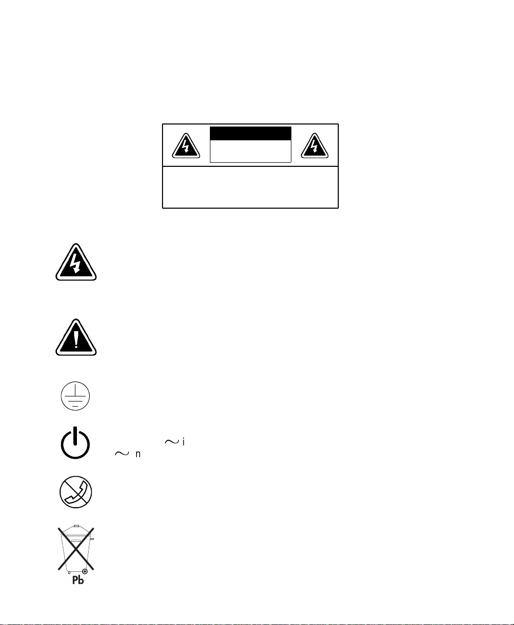
Special Symbols
The following are examples of symbols used on the UPS to alert you to important information:
CCCCAAAAUUUUTTTTIIIIOOOONNNN
RiskofElectricShock
DoNotOpen Cover
CAUTIONToreducethe riskofelectricshock,
Donotremovecover(or back)
Nouser-serviceable partsinside
Refer servicing to the factory
RISK OF ELECTRIC SHOCK- Indicates that a risk of electric shock is present and the
associated warning should be observed.
CAUTION: REFER TO OPERATOR’S MANUAL - Refer to your operator’s manual for
additional information, such as importantoperating and maintenance
instructions.
SAFETY EARTHING TERMINAL - Indicatesthe primary safety ground.
LOAD ON/OFF - Press the button with this symbol to energize the output
µ
receptacles (
µ
indicator is off).
(
RJ-45 RECEPTACLE- For 230V units only: this receptacle provides network
interface connections. Do not plug telephone or telecommunications equipment
into this receptacle.
This symbol indicates that you should not discard the UPS or the UPS batteries
in the trash. The UPS may contain sealed, lead-acid batteries. Batteriesmust be
recycled.
indicator illuminates) or to de-energize the output receptacles
Page 5

TABLE OF CONTENTS
1 Powerware 5115 –One of the Best! 1..................................
2 Installation 3.....................................................
InspectingtheEquipment 3.......................................................
SafetyPrecautions 3............................................................
Installing the UPS 4.............................................................
UPSRear Panels 6..............................................................
3 Operation 11......................................................
Turning the UPS On 11............................................................
Startingthe UPS on Battery 11...................................................
Turning the UPS Off 11...........................................................
StandbyMode 12...............................................................
UPSFrontPanel 12..............................................................
InitiatingtheSelf-Test 12.........................................................
4 Additional UPS Features 13..........................................
Voltage Configuration 13..........................................................
Communication Port 14...........................................................
NetworkTransient Protector 15.....................................................
5 UPS Maintenance 17...............................................
UPSand Battery Care 17..........................................................
Storingthe UPS and Batteries 17..................................................
ReplacingBatteries 18...........................................................
Testing New Batteries 21.........................................................
Recycling the Used Battery 21......................................................
6 Specifications 23..................................................
7 Troubleshooting 27.................................................
SiteWiringFault(120VModelsOnly) 27...............................................
AudibleAlarmsandUPSConditions 27................................................
Silencing an Audible Alarm 27....................................................
Service and Support 31...........................................................
Powerware®5115 User’sGuideSwww.powerware.com
i
Page 6

Table of Contents
ii
Powerware®5115 User’sGuideSwww.powerware.com
Page 7
CHAPTER 1
POWERWARE 5115 – ONE OF THE BEST!
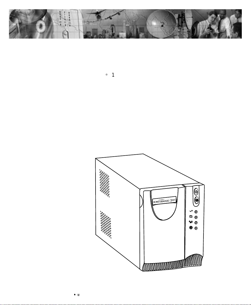
The PowerwareR5115 uninterruptible power system (UPS) protects
your sensitive electronic equipment from basic power problems such as
power failures, power sags, power surges, brownouts, and line noise.
Poweroutagescan occur when you least expect it and power quality can
be erratic.These power problemshave the potentialto corrupt critical
data, destroy unsaved work sessions, and damage hardware— causing
hours of lost productivity and expensive repairs.
Withthe Powerware 5115, you can safely eliminate the effects of power
disturbances and guard the integrity of your equipment.The Powerware
5115’s flexibility to handle an array of network devices makes it the
perfect choice to protectyourLANs, servers, workstations,and other
electricalequipment.
Powerware®5115 User’sGuideSwww.powerware.com
Figure 1. Powerware 5115
1
Page 8

Powerware5115– ONE OF THE BEST!
Becausean integral part of power protectionis power management
software,the Powerware 5115 c ome s fully equipped with a
communication port,serial cable, and a CD containingboth LanSafe III
for networked systemsand FailSafe III for standalonesystems.
Providingoutstanding performance and reliability,the Powerware 5115’s
unique benefits include the following:
S
Advanced Battery Management (ABMt) doubles battery service life,
optimizesrecharge time, and providesadvanced warningbeforethe
end of battery life.
S
Buck and Boost voltage regulation ensures consistentvoltage to your
load by correcting voltage fluctuations.
S
Hot-swappable batteries simplify maintenance by allowingyou to
replacebatteriessafely withoutpoweringdown the critical load.
S
NetworkTransient Protectorguards your modem, fax machine,and
othernetwork communications equipmentfromsurges.
S
Start-on-battery capability allows you to power up the UPS even if
utility power is not available.
S
The Powerware5115 is backed by worldwide agency approvals.
2
Powerware®5115 User’sGuideSwww.powerware.com
Page 9

CHAPTER 2
INSTALLATION
This section explains:
S
Equipment inspection
S
Safetyprecautions
S
UPS installation
S
UPSrear panels
Inspecting the Equipment
If any equipment has been damaged during shipment, keep the shipping
cartonsand packing materialsfor the carrieror place of purchaseand
file a claim for shipping damage. If you discover damage after
acceptance,file a claimfor concealed damage.
To filea claim for shippingdamage or concealeddamage: 1) Filewith
the carrier within 15 days of receiptof the equipment;2) Send a copy of
the damage claim within 15 days to your service representative.
Safety Precautions
Read the followingprecautions before youinstallthe UPS.
IMPORTANT SAFETY INSTRUCTIONS
SAVE THESEINSTRUCTIONS. This manual containsimportantinstructions thatyou
shouldfollowduringinstallation and maintenance of the UPS and batteries.Please
read all instructionsbeforeoperating the equipmentand save this manual for future
reference.
Powerware®5115 User’sGuideSwww.powerware.com
3
Page 10

Installation
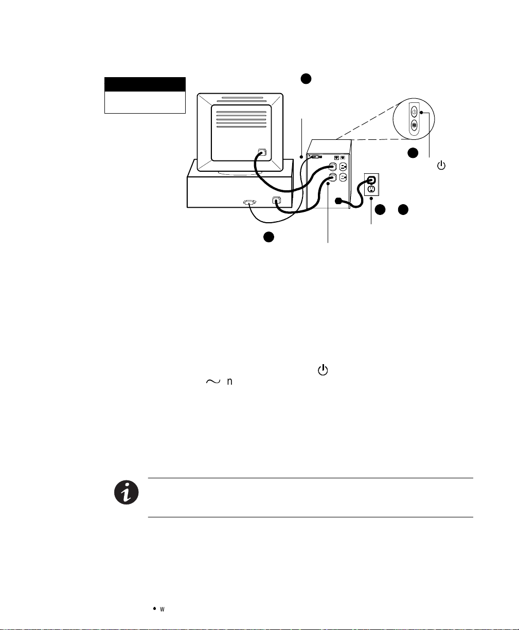
Installing the UPS
The following steps explain how to install the UPS. Figure 2 shows a
typicalinstallation only.See “UPS Rear Panels”on page 6 for the rear
panel of each model.
WARNING
S
ThisUPScontainsitsownenergy source (batteries).Theoutput receptaclesmay
carrylive voltage even when the UPS is not connectedto an AC supply.
S
Donot remove or unplug the input cordwhen the UPSisturned on. This removes
the safety ground from the UPS and the equipment connected to the UPS.
S
To reduce the risk of fireor electricshock,installthisUPSinatemperature and
humiditycontrolled,indoorenvironment,freeofconductivecontaminants.Ambient
temperaturemustnot exceed40
humidity (95% max).
S
To complywithinternationalstandards,thesumofearth leakagecurrent from the
loadconnectedto the UPSmustnot exceed 1.5 mA.
1. If you are installing power management software, connect your
computer to the UPS communication port using the supplied
communication cable.
°C(104°F).Donotoperatenearwaterorexcessive
NOTE If you need to change the factory-setdefaultsfor the output voltageor input
voltagerange,see “VoltageConfiguration”onpage13 before installing the UPS.
2. On 230V models,plug the power cord into the input connector
on the UPS rear panel.
Customer-suppliedpower cordsmust be correctlyrated forthe
UPS(see “Specifications” on page 23). You can also use the
powercordfromthelargestloadifitiscorrectlyrated.
4
Powerware®5115 User’sGuideSwww.powerware.com
Page 11
Installation
NOTE
Thisisa typicalsetup;
yoursetupmay vary.
3. Plug the UPS power cord into a power outlet.
4. Plugthe equipment to be protected into the UPS output
5. Start the UPS by pressing the
1111
Connect communication
cable from computer to
UPS (optional)
5555
Press the ON button
(on the front panel)
2222 & 3333
Connect UPS to power
4444
Connect equipment to UPS
Figure 2. TypicalUPSInstallation (120V Model Shown)
receptacles.
DO NOT protectlaser printerswith the UPS because of the
exceptionally highpower requirementsof the heating elements.
button as shown in Figure 2.
The
indicator illuminates indicating that power is available
µ
fromthe UPS outputreceptacles.
The UPS conductsa self-testand entersNormal mode. If the
alarmbeeps or a UPSalarm indicator stays on,see Table 9 on
page 28.
The installationis complete. To learn how to operate the UPS,
see “Operation” on page 11.
NOTE The batteries charge to90% capacityin approximately3 hours. However, itis
recommendedthatthe batterieschargefor6 to 24 hoursafterinstallation orlong-term
storage.
Powerware®5115 User’sGuideSwww.powerware.com
5
Page 12
Installation
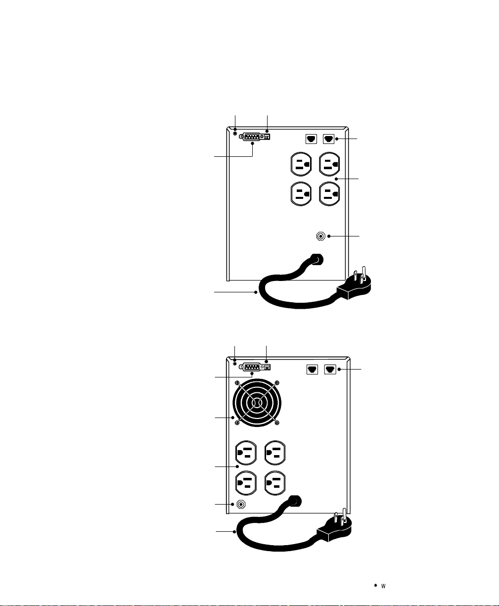
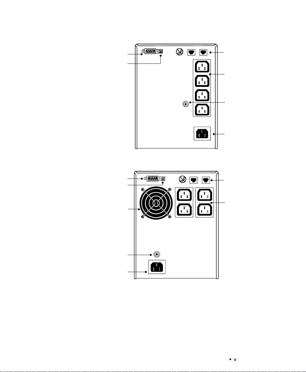
UPS Rear Panels
This section shows the rearpanels of the Powerware 5115 models.
Site Wiring Fault Indicator
Communication Port
6-ft Power Cord
with 5-15 Plug
DIP Switches
Network Transient
Protector
Four 5-15 Receptacles
Input Overcurrent
Protector
Figure 3. 500 VA,120VRearPanel
DIP SwitchesSite Wiring Fault Indicator
Communication Port
Fan
Four 5-15 Receptacles
Input Overcurrent
Protector
6-ft Power Cord
with 5-15 Plug
Network Transient
Protector
Figure 4. 750 VA,120VRearPanel
6
Powerware®5115 User’sGuideSwww.powerware.com
Page 13

Installation
DIP SwitchesSite Wiring Fault Indicator
Communication Port
Fan
Four 5-15 Receptacles
Input Overcurrent
Protector
6-ft Power Cord
with 5-15 Plug
Communication Port
Network Transient
Protector
T wo5-15Receptacles
Figure 5. 1000 VA,120VRearPanel
DIP SwitchesSite Wiring Fault Indicator
Network Transient
Protector
6-ft Power Cord
with 5-15 Plug
Powerware®5115 User’sGuideSwww.powerware.com
Fan
Six 5-15 Receptacles
Input Overcurrent
Protector
Figure 6. 1400 VA,120VRearPanel
7
Page 14
Installation
Communication Port
DIP Switches
Communication Port
DIP Switches
Fan
Network Transient
Protector
Four 10A, IEC-320
Receptacles
Input Overcurrent
Protector
10A, IEC-320
Input Connector
Figure 7. 500 VA,230VRearPanel
Network Transient
Protector
Four 10A, IEC-320
Receptacles
Input Overcurrent
Protector
10A, IEC-320
Input Connector
Figure 8. 750 VA,230VRearPanel
8
Powerware®5115 User’sGuideSwww.powerware.com
Page 15

Installation
Communication Port
DIP Switches
Fan
T wo10A,IEC-320
Receptacles
Input Overcurrent
Protector
10A, IEC-320
Input Connector
Communication Port
DIP Switches
Network Transient
Protector
Four 10A, IEC-320
Receptacles
Figure 9. 1000 VA,230VRearPanel
Network Transient
Protector
Fan
Six 10A, IEC-320
Receptacles
Input Overcurrent
Protector
Powerware®5115 User’sGuideSwww.powerware.com
10A, IEC-320
Input Connector
Figure 10. 1400 VA,230VRearPanel
9
Page 16

Installation
10
Powerware®5115 User’sGuideSwww.powerware.com
Page 17

CHAPTER 3
OPERATION
Thissectiondescribes:
S
Turning the UPS on and off
S
Starting the UPS on battery
S
Standby mode
S
The UPS front panel and LEDs
S
Initiatingthe self-test
Turning the UPS On
To turn on the UPS, press the button on the front panel (shown in
Figure 11). After the UPS is turned on, it conducts a self-test and enters
Normal mode. The
available from the UPS outputreceptacles.
Starting the UPS on Battery
To turn on the UPS without using utility power, press and hold the
button for two seconds. When the UPS starts on battery, it does not
conducta self-testto conserve battery power.
indicator illuminates indicating that power is
µ
NOTE TheUPSdoes notauto-detecttheinputfrequencywhenstartingonbattery;the
defaultisthe last frequency used by the UPS.
Turning the UPS Off
To turn off the UPS, press the buttonon the frontpanel and then
unplug the UPS from the power outlet. If you do not unplug the UPS, it
remainsin Standby mode.
Powerware®5115 User’sGuideSwww.powerware.com
11
Page 18

Operation
Standby Mode
UPS Front Panel
When the UPS is turned off and remains plugged into a power outlet,
the UPS is in Standbymode. The battery recharges whennecessaryand
the
indicator is off, indicating that power is not available from the
µ
UPSoutput receptacles.
The UPS front panel indicatesthe UPS statusand also identifies
potential power problems. Figure 11 shows the UPS frontpanel
indicators and controls.
On/Off Button
T est/AlarmReset Button
If the alarm beeps or any alarm indicators are on, see Table9 on page 28
to identify and correctthe problem.
Initiating the Self-Test
Press and hold the button for three seconds to initiate the self-test. If
the UPS findsa problem,an LED indicates where the problem is. For
more information, see “Troubleshooting” on page 27.
NOTE The batteries must be fullychargedand the UPSmustnot be in Battery mode
to perform the self-test.
12
Power On Indicator (Green)
On Battery Indicator (Yellow)
Overload Indicator (Red)
Service Indicator (Red)
Figure 11. UPS Front Panel
Powerware®5115 User’sGuideSwww.powerware.com
Page 19

CHAPTER 4
ADDITIONAL UPS FEATURES
Thissectiondescribes:
S
Changing the voltage configuration
S
Using the communication port
S
The Network TransientProtector
VoltageConfiguration
The DIP switcheson the rear panel of each unit(see Figure12) areused
to configure the output voltage and input voltage range.
1. The UPS must be completely shutdown.
Turn the UPS off by pressing the
and then unplug the UPS.
2. Set the DIP switchesaccording to the configurations in Table1.
3. Plugthe UPS into a power outlet and press the
turn the UPS on.
UPS Rear Panel
buttononthefrontpanel
button to
Powerware®5115 User’sGuideSwww.powerware.com
21
OFF
ON
Figure 12. DIP Switches
13
Page 20

Additional UPS Featu res
Table 1. DIPSwitchSettings
*Default position
Communication Port
To establish communication between the UPS and a computer, connect
your computer to the UPS communication port using the supplied
communication cable.
Whenthe communicationcable is installed,power management
software can exchangedata with the UPS. The software polls the UPS for
detailed information on the status of the power environment. If a power
emergency occurs,the software initiatesthe saving of all data and an
orderlyshutdown of the equipment.
120V Models
Output Voltage Input Voltage Range DIPSwitch1 DIPSwitch2
110V 99V-116V ON OFF/ON
120V* 108V–127V* OFF OFF/ON
230V Models
Output Voltage Input Voltage Range DIPSwitch1 DIPSwitch2
220V 198V–233V ON OFF
230V* 207V–243V* OFF OFF/ON
240V 216V–254V ON ON
14
UPS Rear Panel
87
6
1
245
9
3
Figure 13. Communication Port
Powerware®5115 User’sGuideSwww.powerware.com
Page 21

Table 2. Communication Port Pin Assignment
Pin
Number
SignalName Function Direction
Additional UPS Featu res
from the UPS
1 Low Batt Low Battery relay contact; 20 mA, 30 Vdc
2 RxD T ransmittoexternaldevice Out
3 TxD Receivefromexternal device In
4 DTR PnP(PlugandPlay) from external device (tied
5 GND Signal common (tied to chassis) —
6 DSR T oexternal device (tied to Pin 4) Out
7 — No Connection —
8 AC Fail AC Fail relay contact; 20 mA, 30 Vdc contact
9 Power Source +V (8 to 24 volts DC power) Out
Network TransientProtector
The Network TransientProtector,shownin Figure14, is located on the
rearpanel and has jacks labeled IN and OUT. Thisfeature
accommodatesa singleRJ-45 (10BaseT) network connector.
Low voltage models can also accommodate an RJ -11 telephone
connector that provides protectionfor modems, fax machines,or other
telecommunications equipment. As with most modem equipment, it is
not advisable to use thisjack in digital PBX (Private Branch Exchange)
environments.
Connect the input connector of the equipment you are protecting to the
jack labeled IN. Connectthe output connector to the jack labeledOUT.
Out
contact rating
In
to Pin 6)
Out
rating
Powerware®5115 User’sGuideSwww.powerware.com
OUT IN
IN
OUT
NETWORKTRANSIENTPROTECTOR
Figure 14. Network Transient Protector
15
Page 22

Additional UPS Featu res
16
Powerware®5115 User’sGuideSwww.powerware.com
Page 23

CHAPTER 5
UPS MAINTENANCE
This section explains how to:
S
Care for the UPS and batteries
S
Replace the batteries
S
Test new batteries
S
Recycleused batteries
UPS and Battery Care
Forthe best preventivemaintenance, keep the area aroundthe UPS
clean and dust-free. If the atmosphere is very dusty, clean the outsideof
the system witha vacuumcleaner.
Forfull battery life,keep the UPS at an ambienttemperature of
25°C (77°F).
Storing the UPS and Batteries
If youstore the UPS for a long period, recharge the batteryevery
6 months by plugging the UPS into a powe r outlet. The batteries charge
to 90% capacity inapproximately 3 hours.However, it is recommended
that the batterieschargefor 6 to 24 hoursafter long-term storage.
Powerware®5115 User’sGuideSwww.powerware.com
17
Page 24

UPS Maintenance
Replacing Batteries
The hot-swappable battery feature allows youto replace the UPS
batteries easily without turning the UPS off or disconnecting the load.
If you prefer to remove input power to change the battery, press the
button and then unplug the UPS.
Consider all warnings, cautions, and notesbefore replacingbatteries.
S
S
S
S
WARNING
Batteriescanpresenta risk of electricalshock or burn from highshort circuit
current.The followingprecautionsshouldbeobserved:1) Remove watches,rings,
or other metal objects;2)Usetoolswithinsulatedhandles;3)Donotlaytoolsor
metalpartson top of batteries.
ELECTRICENERGYHAZARD. Do notattempt to alterany battery wiring or
connectors.Attempting to alter wiring can causeinjury.
Replacebatterieswiththe same number andtype of batteriesasoriginally
installed in the UPS.
DONOTDISCONNECTthebatterieswhilethe UPS is in Battery mode.
18
CAUTION
Pullthe battery out onto a flat,stablesurface.Thebattery is unsupported when you
pullitout of the UPS.
Powerware®5115 User’sGuideSwww.powerware.com
Page 25

Use the following steps to replacethe batteries:
1. Pullthe top left cornerforwardand remove the frontpanel.
2. Slide up and remove the metal battery cover.
UPS Maintenance
3. 500 VA units. Disconnect the red battery cable and then
disconnect the black batterycable. Pull the battery out onto a
flat,stable surface.
Powerware®5115 User’sGuideSwww.powerware.com
19
Page 26

UPS Maintenance
4. 750–1400 VAunits.Disconnect the redbattery cable and then pull
the battery outonto a flat,stable surface. Disconnectthe black
battery cable to the UPS as shown.
750/1000 VA
20
1400 VA
Powerware®5115 User’sGuideSwww.powerware.com
Page 27

5. Replace the battery.See “Recyclingthe Used Battery” forproper
6. Connectthe black battery cable to the new battery and then
7. Reinstall the batte ry.
8. Reinstall the meta l battery cover and front panel.
Testing New Batteries
NOTE It is recommended that the batteriescharge for 6 to 24 hours before testing.
Press and hold the button for three seconds to initiate a self-test.
The 15-second test automatically distributes the load to the batteries and
tests the battery’s performance. While the test is in progress,the
indicators cycle through and the alarm sounds. When complete, the UPS
returns to N ormal mode as indicated by the
If there is a problem with the battery, the alarm beeps, the
illuminates and the indicator flashes.Check the battery connections
and be sure the battery is fully charged. Call your service representative
if the problem persists.
disposal.
connectthe redbattery cable.
µ
indicator.
UPS Maintenance
+
---
indicator
Recycling the Used Battery
Contactyourlocal recycling or hazardouswaste centerfor information
on proper disposal of the used battery.
S
Donot dispose of the battery or batteriesina fire. Batteries may explode. Proper
disposalofbatteriesisrequired.Referto your localcodesfordisposal
requirements.
S
Donotopenormutilatethebatteryorbatteries.Releasedelectrolyte is harmful to
the skin and eyes. It may be toxic.
DonotdiscardtheUPSortheUPSbatteriesinthe trash. Thisproductcontainssealed,
lead-acidbatteriesandmustbe disposed of properly. Formore information,contact
your local recycling or hazardous waste center.
Powerware®5115 User’sGuideSwww.powerware.com
WARNING
CAUTION
21
Page 28

UPS Maintenance
22
Powerware®5115 User’sGuideSwww.powerware.com
Page 29

CHAPTER 6
SPECIFICATIONS
Thissectionprovidesthe followingspecifications for the Powerware
5115 models:
S
W eights and dimensions
S
Electrical input and output
S
Environmental and safety
S
Battery
Table 3. Model List and Mechanical
120V Models 230VModels
UPS Models PW5115 500
PW5115 750
PW5115 1000
PW5115 1400
UPS Dimensions
(WxHxD)
UPS Weight 500 VA: 7.8 kg (17.2 lb)
500 VA: 15.0 x 19.3 x 27.0 cm (5.9²x7.6²x 10.6²)
750–1000 VA: 15.0 x 19.3 x 33.5 cm (5.9
1400 VA: 15.0 x 19.3 x 39.0 cm (5.9
750 VA: 12.4 kg (27.3 lb)
1000 VA: 12.6 kg (27.8 lb)
1400 VA: 16.8 kg (37.0 lb)
PW5115 500i
PW5115 750i
PW5115 1000i
PW5115 1400i
²
x7.6²x 13.2²)
²
x7.6²x 15.4²)
Table 4. Electrical Input
120V Models 230VModels
NominalVoltage 110V ,120V selectable 220V ,230V, 240V selectable
VoltageRange ±20% for nominal voltage at full load
NominalFrequency 45–65 Hz, 50/60 Hz auto-sensing
Efficiency (Normalmode) 95%
Noise Filtering Full-time EMI/RFI filtering
Overcurrent Protection Resettable input overcurrent protector
Connections 6-ft, 5-15P power cord (90° angle) 10A, IEC-320 input connector
Powerware®5115 User’sGuideSwww.powerware.com
23
Page 30

Specifications
Table 5. Electrical Output
120V Models 230V Models
PowerLevels (ratedat
nominalinputs)
PowerFactor 500 VA, 0.64
Regulation(Normal mode) -10% to +6% of nominal voltage
Regulation(Batterymode),
NominalVoltage ±5%
VoltageWaveform Sinewave
Overcurrent Protection Inverter saturation current limited
OutputReceptacles 500–750 VA: (4) 5-15
Same as selected nominal input voltage
110, 120V
1000–1400 VA: (6) 5-15
500 VA, 320W
750 VA, 500W
1000 VA, 670W
1400 VA, 950W
750–1400 VA, 0.67
Same as selected nominal input voltage
220, 230, 240V
500–750 VA: (4) 10A, IEC-320
1000–1400 VA: (6) 10A, IEC-320
Table 6. Environmental and Safety
120V Models 230V Models
OperatingTemperature Up to 1,500 meters: 0°C to 40°C (32°F to 104°F); UL tested 25°C (77°F)
Above 1,500 meters: 0°C to35°C (32°F to 95°F)
Transit/Storage
Temperature
Relative Humidity 5–95% noncondensing
OperatingAltitude Up to 3,000 meters above sea level
AudibleNoise Less than 45 dBA typical
SurgeSuppression ANSI C62.41 Category A (formerly IEEE 587)
SafetyConformance UL 1778; UL 497A;
CAN/CSA C22.2, No. 107.1
Safety Markings UL,cUL UL, cUL,CE,TUV,C-Tick
EMC(ClassB) FCC Part 15, ICES-003 EN 50091-2, FCC Part 15, ICES-003
-15°C to 55°C (5°F to 131°F)
UL 1778, UL 497A (data line only);
CAN/CSA C22.2, No. 107.1;
EN 50091-1-1 and IEC 60950
24
Powerware®5115 User’sGuideSwww.powerware.com
Page 31

Specifications
Table 7. Battery
Configuration 500 VA: (1) 12V,9Ahinternal battery
750 VA: (2) 12V,7.2 Ah internal batteries
1000 VA: (2) 12V,9 Ah internal batteries
1400 VA: (3) 12V,9 Ah internal batteries
Voltage 500 VA: 12 Vdc
750–1000 VA: 24 Vdc
1400 VA: 36 Vdc
Type Sealed, maintenance-free, valve-regulated, lead-acid
Charging Advancedchargingforfasterrecovery; less than 3 hours to 90% usable capacity at nominal
line and no supplementary power supply load
Monitoring Advanced monitoring for earlier failure detection and warning
Table 8. Battery Run Times(in Minutes)
UPS ModelsbyVA Ratings
Load(VA) Watts 500 750 1000 1400
200 128 17 38 41 58
300 192 11 27 28 41
500 320 5 14 15 28
600 402 9 10 19
750 503 6 8 14
900 603 6 10
1000 670 5 8
1200 804 6
1400 938 5
NNNNOOOOTTTTEEEE Battery times are approximate and may vary depending on the load configuration and battery charge.
Powerware®5115 User’sGuideSwww.powerware.com
25
Page 32

Specifications
26
Powerware®5115 User’sGuideSwww.powerware.com
Page 33

CHAPTER 7
TROUBLESHOOTING
This section explains:
S
Site wiringfault on 120V models
S
UPS alarms and conditions
S
How to silence an alarm
S
Service and support
Site Wiring Fault (120V Models Only)
The Site Wiring Fault indicator on the UPS rear panel illuminates if the
ground wire connection does not exist or the line and neutral wires are
reversed in the line receptacle.Thisindicatorstayson untilthe
condition is resolved. Have a qualified electriciancorrectthe wiring
fault. The UPS operates when the indicator is illuminated, but does not
provideratednoiseandsurgesuppression.
Audible Alarms and UPS Conditions
The UPS has an audible alarm feature to alert you of potentialpower
problems. Whenthe alarm is activated,the UPSbeeps in different
intervals according to a particularcondition. Use Table 9 to determine
and resolvethe UPS alarms and conditions.
Silencing an Audible Alarm
To silence the alarm foran existingfault,pressthe button. If UPS
statuschanges,the alarm beeps, overriding the previous alarm silencing.
The alarm does not silence if there is a UPS fault, low battery condition,
or if the battery needs to be replaced.
Powerware®5115 User’sGuideSwww.powerware.com
27
Page 34

Troubleshooting
b
IndicatorLegend
Unlit
Lit
Flashing
Table 9. Troubleshooting
AlarmorCondition PossibleCause Action
The indicator is not
µ
on; the UPS does not start.
The UPS operates in Battery mode
only,eventhoughnormal utility
power is present.
UPS does not provide the expected
backup time.
1 beep every 4 seconds. Utility power failure. TheUPS is powering your equipment with its internal
1 beep every 2 seconds. The battery is running low.
The power cord is not
connected.
The wall outlet is faulty. Have a qualified electrician test and repair the outlet.
The input overcurrent
protector is open.
The battery may be fully
discharged because of:
S
long-term storage
S
frequent power outages
S
end of battery life
Normal operation. None. The UPS is operating in Normal mode and
Check the power cordconnections.
Save your work andturn off your equipment. Turnoff
the UPS. Reduce the load, then press the input
overcurrent protector on the UPS rear panel.
Plug the UPS into a power outlet for 24 hours to charge
the battery.Pressthe button, if the alarm beeps,
see “Replacing Batteries” on page 18 to replace the
attery.
During extended power outages, turn off the UPS after
saving your work and shutting down your computer to
conserve battery charge.
automatically provides consistent voltage with the
Buck and Boost feature.
battery.Ifthisis an extended power outage, saveyour
work and turn off your equipment to conserve battery
power.
2 minutes or less of battery power remains
(depending on load and battery charge).
Prepare for a shutdown. Save your work and turnoff
your equipment. The alarm cannot be silenced.
28
Powerware®5115 User’sGuideSwww.powerware.com
Page 35

Troubleshooting
ActionPossible CauseAlarmorCondition
1 beep every 2 seconds.
1 beep per second.
1 beep per second.
Continuous beep. Battery test failed. Check the battery connections and be sure the battery
Continuous beep. UPS internal temperature is
The UPS is running on
battery power because the
input voltage is too high or
too low.
Power requirements exceed
UPS capacity (overload is
greater than 120%) or the
load is defective.
The UPS is onbattery,and
the power requirements
exceed UPS capacity
(overload is greater than
120%) or the load is
defective.
too high.
Correct the input voltage, if possible. The UPS
continues to operate on battery until the condition is
corrected or the battery is completely discharged.
If the condition persists, the input voltage in your area
may differ from theUPS nominal. Change the UPS
input voltage to match your local voltage (see
“Voltage Configuration” on page 13).
The UPS will automatically shut down in 3 minutes.
Save your work immediately and turn off your
equipment. TurnofftheUPS.
Remove some of the equipment from the UPS. You
may need to obtain a larger capacity UPS.
Shutdown is imminent (30 seconds). Save your work
and turn off your equipment. T urnoff theUPS.
Remove some of the equipment from the UPS. You
may need to obtain a larger capacity UPS.
is fully charged.
If the indicator still flashes, see “UPS
Maintenance” on page 17 to replace the battery.Call
your service representative if the problem persists.
Shutdown is imminent. Save your work and turn off
your equipment. TurnofftheUPS.
Clear vents and remove any heat sources. Ensure the
airflow around the UPS is not restricted. Wait at least
5 minutes and restart the UPS. If the condition
persists, contact your service representative.
Continuous beep. UPS fanfault (750–1400 VA
models only).
Powerware®5115 User’sGuideSwww.powerware.com
Save your work andturn off your equipment. Turnoff
the UPS. Contact your service representative.
29
Page 36

Troubleshooting
ActionPossible CauseAlarmorCondition
3 beeps every 10
seconds.
Continuous beep. The output wave is
Continuous beep.
Failed attempt to start the
UPS on battery.
abnormal while the UPS is
on battery.
The output voltage is below
or above the limit while the
UPS is on battery.
Plug the UPS into a power outlet for 24 hours to charge
the battery.Aftercharging the battery,pressandhold
the button for 3 seconds; then check the
indicator.
If the indicator still flashes, see “UPS
Maintenance” on page 17 to replace the battery.
Shutdown is imminent. Save your work and turn off
your equipment. TurnofftheUPS. Contact your service
representative.
Save your work andturn off your equipment. Turnoff
the UPS. Contact your service representative.
30
Powerware®5115 User’sGuideSwww.powerware.com
Page 37

Service and Support
If youhave any questionsor problems with the UPS, call your Local
Distributor
and ask for a UPS technical representative.
In the United States 1111----888800000000----333366665555----4444888899992222
In Canada 1111----888800000000----444466661111----9999111166666666
All other countries 1111----999911119999----888877770000----3333111144449999
Pleasehave the followinginformation readywhen you call the Help
Desk:
S
Model number
S
Serial number
S
Version number (if available)
S
Date of failure or problem
S
Symptoms of failureor problem
S
Customer returnaddressand contactinformation
If repair is required, you will be given a Returned Material Authorization
(RMA) Number.This number must appear on the outside of the package
and on the Bill Of Lading (if applicable). Use the original packaging or
request packaging from the Help Desk or distributor.Unitsdamaged in
shipment as a resultof improper packaging are not covered under
warranty. A replacementor repairunitwill be shipped, freightprepaid
for all warrantied units.
Troubleshooting
or the Help Desk at one of the following telephone numbers
NOTE For criticalapplications, immediate replacementmay be available. Callthe
Help Desk for the dealer ordistributornearestyou.
Powerware®5115 User’sGuideSwww.powerware.com
31
Page 38

Troubleshooting
32
Powerware®5115 User’sGuideSwww.powerware.com
 Loading...