

Page 1
This .pdf document is bookmarked
Operating Instructions and Parts Manual
Model PM2700 Shaper
Model: 270 0
Powermatic
427 New Sanford Road
LaVergne, TN 37086 Part No. M-1280100C
Ph.: 800-274-6848 Revision G1 02/2014
www.powermatic.com Copyright © 2014 Powerm atic
Page 2

Warranty and Service
Powermatic warrants every product it sells against manufacturers’ defects. If one of our tools needs service or repair,
please contact Technical Service by calling 1-800-274-6846, 8AM to 5PM CST, Monday through Friday.
Warranty Period
The general warranty lasts for the time period specified in the literature included with your product or on the official
Powermatic branded website.
• Powermatic products carry a limited warranty which varies in duration based upon the product. (See chart
below)
• Accessories carry a limited warranty of one year from the date of receipt.
• Consumable items are defined as expendable parts or accessories expected to become inoperable within a
reasonable amount of use and are covered by a 90 day limited warranty against manufacturer’s defects.
Who is Covered
This warranty covers only the initial purchaser of the product from the date of delivery.
What is Co vered
This warranty covers any defects in workmanship or materials subject to the limitations stated below. This warranty
does not cover failures due directly or indirectly to misuse, abuse, negligence or accidents, normal wear-and-tear,
improper repair, alterations or lack of maintenance.
Warranty Limitations
Woodworking products with a Five Year Warranty that are used for commercial or industrial purposes default to a
Two Year Warranty. Please contact Technical Service at 1-800-274-6846 for further clarification.
How to Get Technical Support
Please contact Technical Service by calling 1-800-274-6846. Please note that you will be asked to provide proof
of initia l p u rch a s e whe n calling. If a product requires further inspection, the Technical Service representative will
explain and assist with any additional action needed. Powermatic has Authorized Service Centers located throughout
the United States. For the name of an Authorized Service Center in your area call 1-800-274-6846 or use the Service
Center Locator on the Powermatic website.
More Informa tion
Powermatic is constantly adding new products. For complete, up-to-date product information, check with your local
distributor or visit the Powermatic website.
How S tate Law Applies
This warranty gives you specific legal rights, subject to applicable state law.
Limitations on This Warranty
POWERMATIC LIMITS ALL IMPLIED WARRANTIES TO THE PERIOD OF THE LIMITED WARRANTY FOR EACH
PRODUCT. EXCEPT AS STATED HEREIN, ANY IMPLIED WARRANTIES OF MERCHANTABILITY AND FITNESS
FOR A PARTICULAR PURPOSE ARE EXCLUDED. SOME STATES DO NOT ALLOW LIMITATIONS ON HOW
LONG AN IMPLIED WARRANTY LASTS, SO THE ABOVE LIMITATION MAY NOT APPLY TO YOU.
POWERMATIC SHALL IN NO EVENT BE LIABLE FOR DEATH, INJURIES TO PERSONS OR PROPERTY, OR
FOR INCIDENTAL, CONTINGENT, SPECIAL, OR CONSEQUENTIAL DAMAGES ARISING FROM THE USE OF
OUR PRODUCTS. SOME STATES DO NOT ALLOW THE EXCLUSION OR LIMITATION OF INCIDENTAL OR
CONSEQUENTIAL DAMAGES, SO THE ABOVE LIMITATION OR EXCLUSION MAY NOT APPLY TO YOU.
Powermatic sells through distributors only. The specifications listed in Powermatic printed materials and on the official
Powermatic website are given as general information and are not binding. Powermatic reserves the right to effect at
any time, without prior notice, those alterations to parts, fittings, and accessory equipment which they may deem
necessary for any reason whatsoever.
Product Listing with Warranty Period
90 Days – Parts; Consumable items
1 Year – Woodworking Machinery used for industrial or commercial purposes
5 Year – Woodworking Machinery
NOTE: Powermatic is a division of JPW Industries, Inc. References in this document to Powermatic also apply to
JPW Industries, Inc., or any of its successors in interest to the Powermatic brand.
2
Page 3

Table of Contents
Warranty and Servic e .............................................................................................................................. 2
Table of Contents .................................................................................................................................... 3
Warnings ................................................................................................................................................. 4
Warning ................................................................................................................................................... 6
Introduction ............................................................................................................................................. 7
Specifica tions ................................................................................................................ .......................... 7
Unpac king ............................................................................................................................................... 8
Shipping Contents ................................................................................................................................ 8
Installing .................................................................................................................................................. 8
Assembly ................................................................................................................................................ 9
Mounting the Fenc e ............................................................................................................................. 9
Electri c al Connec tions ............................................................................................................................. 9
General Information ............................................................................................................................. 9
Extension Cords................................................................................................................................. 10
Adjustments ................................................................................................................... ....................... 1 1
Fence Assembly Movement ............................................................................................................... 11
Coplanar Alignment............................................................................................................................ 12
Ram Dial Calibration .......................................................................................................................... 13
Spindle G ib Adjust men t ...................................................................................................................... 14
Featherboard Hold-downs .................................................................................................................. 14
Spindle Asse mbly In stallatio n ............................................................................................................. 15
Spindle Asse mbly Remova l ................................................................................................................ 15
Shaper Cutter Installation ................................................................................................................... 16
Router Collet (O ptional) Installati on .................................................................................................... 16
Changing Cutter S peed ...................................................................................................................... 17
Drive Belt Tension .............................................................................................................................. 17
Precision Miter Gauge ........................................................................................................................ 18
Handwheel Adjustments ..................................................................................................................... 11
Belt Replacement ............................................................................................................................... 17
Operating Controls ................................................................................................................................ 19
Start/Stop ........................................................................................................................................... 19
Safety Ke y .................................................................................................................... ..................... 1 9
Digital Readout .................................................................................................................................. 19
Operations............................................................................................................................................. 2 0
Special Cuts .......................................................................................................................................... 29
Troubleshooting for PM2700 Shaper...................................................................................................... 32
Optional Accessories ............................................................................................................................. 3 3
Parts ..................................................................................................................................................... 34
Ordering Replacement Parts .............................................................................................................. 34
Table – Parts List ............................................................................................................................... 34
Table – Assembly Drawing ................................................................................................................. 35
Fence – Parts List .............................................................................................................................. 36
Fence – Assembly Drawing ................................................................................................................ 37
Frame and Motor – Parts List ............................................................................................................. 38
Elevator – Parts List ........................................................................................................................... 40
Elevator – Assembly Drawing ............................................................................................................. 41
Caster Assembly – Parts List ............................................................................................................. 42
Caster Assembly Drawing .................................................................................................................. 43
Spindle Assembly – Parts List ............................................................................................................ 44
Spindle Assembly Drawing- ................................................................................................................ 45
Cabinet and Base – Part s Li st ............................................................................................................ 46
Cabinet and Base .............................................................................................................................. 48
Wiring Diagrams .................................................................................................................................... 49
3HP/5HP, 230V, 1Phase .................................................................................................................... 49
5HP, 230V, 3Phase............................................................................................................................ 50
5HP, 460V, 3Phase............................................................................................................................ 51
3
Page 4

Warnings
1. Read and understand the ent ire owner's manual bef or e att em pting assembly or operation.
2. Read and understand the warnings po sted on the m achine and i n thi s manual. Fail ure to comply wit h
all of these warnings m ay cause seriou s i njury.
3. Replace the warning labels if they become obscured or removed.
4. This shaper is designed and int ended for use by proper ly t rained and experi enced personnel onl y. If
you are not f amiliar wit h the proper and safe operati on of a shaper, do not use unt il proper training
and knowledge have been obtained.
5. Do not use this shaper for other than its intended use. If used for other purposes, Powermatic
disclaim s any real or i mplied warrant y and h olds itsel f harml ess from any injury t hat may r esult f rom
that use.
6. Always wear appr oved safety glasses/face shi elds while u si ng this shaper. Everyday ey eglasses only
have impact resistant lenses; they are not safety glasses.
7. Before operati ng this shaper, rem ove tie, rings, watches and other j ewelry, and r oll sleeves up past
the elbows. Remove all loose clothing and c onfine long hair. Non-sli p footwear or anti-skid fl oor st r ips
are recommended. Do not wear gloves.
8. Wear ear protector s (plugs or muffs) during ext ended peri ods of oper ation.
9. Some dust created by power sanding, shaping, grinding, drilling and other construction activities
contain chemi cals known to cause cancer , bir th defects or other r eproductiv e harm . Some exampl es
of these chemic als are:
• Lead from lead based paint.
• Crystalli ne sil ic a from bricks, cement and other m asonry pr oduc ts.
• Arsenic and chromium from chemically treated lumber .
Your risk of exposure varies, depending on how often you do this type of work. To reduce your
exposure to these chemicals, work in a well-ventilated area and work with approved safety
equipment, such as face or dust masks that are specifically designed to filter out microscopic
particles.
10. Do not operate this machi ne while tired or under the influence of drugs, alcohol or any medication.
11. M ak e c er tain the machine is properl y grounded.
12. M ak e all machine adjustments or maintenance with the m ac hine unplugged from the power source. A
machine under repair should be RED TAGGED to show it must not be used until maintenance is
complete.
13. Remove adjusting keys and wrenches. Form a habit of checking to see that keys and adjusting
wrenches are removed from the machine before turning it on.
14. Keep safety guards in place at all times when the machi ne is in use. If removed for maintenance
purposes, use extreme caution and replace the guards immediately.
15. Check damaged parts. Before further use of the machine, a guard or other part that is damaged
should be carefully checked to determine that it will operate properly and perform its intended
function. Chec k for alignment of moving par ts, binding of moving parts, breakage of parts, mounting
and any other condi ti ons that m ay affect its operati on. A guard or ot her part that i s damaged should
be properly repaired or replaced.
16. P r ov ide for adequate space surroundi ng work ar ea and non-glare, ov er head lighting.
17. K eep the floor around the machi ne cl ean and free of scrap material, oil and grease.
18. K eep v isitors a safe distance fr om the work area. K eep chi ldren away.
4
Page 5

19. M ak e y our workshop child proof wit h padloc k s, m aster swit c hes or by r em ov ing safety keys.
20. K eep v isitors a safe distance fr om the work area. K eep chi ldren away.
21. M ak e y our workshop child proof wit h padloc k s, m aster swit c hes or by r em ov ing safety keys.
22. Giv e your work undivi ded attention. Looki ng around, carryi ng on a conversati on and “horse-play” ar e
careless acts that can r esul t in serious injury.
23. Maintain a balanced stance at all times so that you do not fall or lean against the blade or other
moving part s. Do not over r eac h or use excessive force to perform any mac hine oper ation.
24. Use the ri ght t ool at the cor rect speed and feed r ate. Do not for ce a tool or attachment to do a job for
which it was not designed. T he ri ght tool will do the job better and safer.
25. Use recom mended accessories; improper accessories may be hazardous.
26. Maintai n tools with care. Keep cutter sharp and clean f or the best and safest perform ance. Follow
instructions for lubricating and changing accessories.
27. Check t he cutter f or crack s or missing teet h. Do not use a cracked c utter or one wi th missing teeth or
improper set. Make sure the c utt er i s securel y locked on the arbor.
28. Keep hands clear of the cutter area. Do not reach past the cutter to clear parts or scrap with the
shaper running. Avoi d awkward operations an d hand posi ti ons where a sudden sli p coul d cause your
hand to contact the c utt er .
29. Do not attem pt to shape boards with loose knots or with nails or other foreign mat eri al, on its surfac e.
Do not attempt to shape twisted, warped, bo wed or “i n wind” stoc k unl ess one edge ha s been joi nt ed
for guiding purpose s prior to shaping.
30. Do not at tempt to shape long or wide board s unsupported where spring or weight coul d cause the
board to shift posit ion.
31. A lways use safety devices for al l oper ations where they can be used.
32. B e sure t o c hec k the direction of spindl e rotation before use.
33. Turn off the mac hine before cl eaning. Use a brush or compressed air to rem ov e c hips or debris — do
not use your hands.
34. Do not stand on the machine. Seri ous i njury could occur if the machine tips over.
35. Never leave the mac hine r unning unattended. Turn the power off and do not leav e the machine until it
comes to a complete stop.
36. Remove loose items and unnecessary work pieces from the area before starting the machine.
Familiariz e you rself with the following safety no tices used in this manual:
This means that if precautions are not heeded, it may result in minor injury and/or
possible machine damage.
This means that if precauti ons are not heeded, it may result in serious injury or possibly
even death.
5
Page 6
Warning
Short stock – Never shape stock less than 12
inches in length without special fixtures. Where
practic al, shape longer stoc k and c ut to size.
12 inch rule – When shaping, never allow your
hands to come closer than 12 inches to the
cutters.
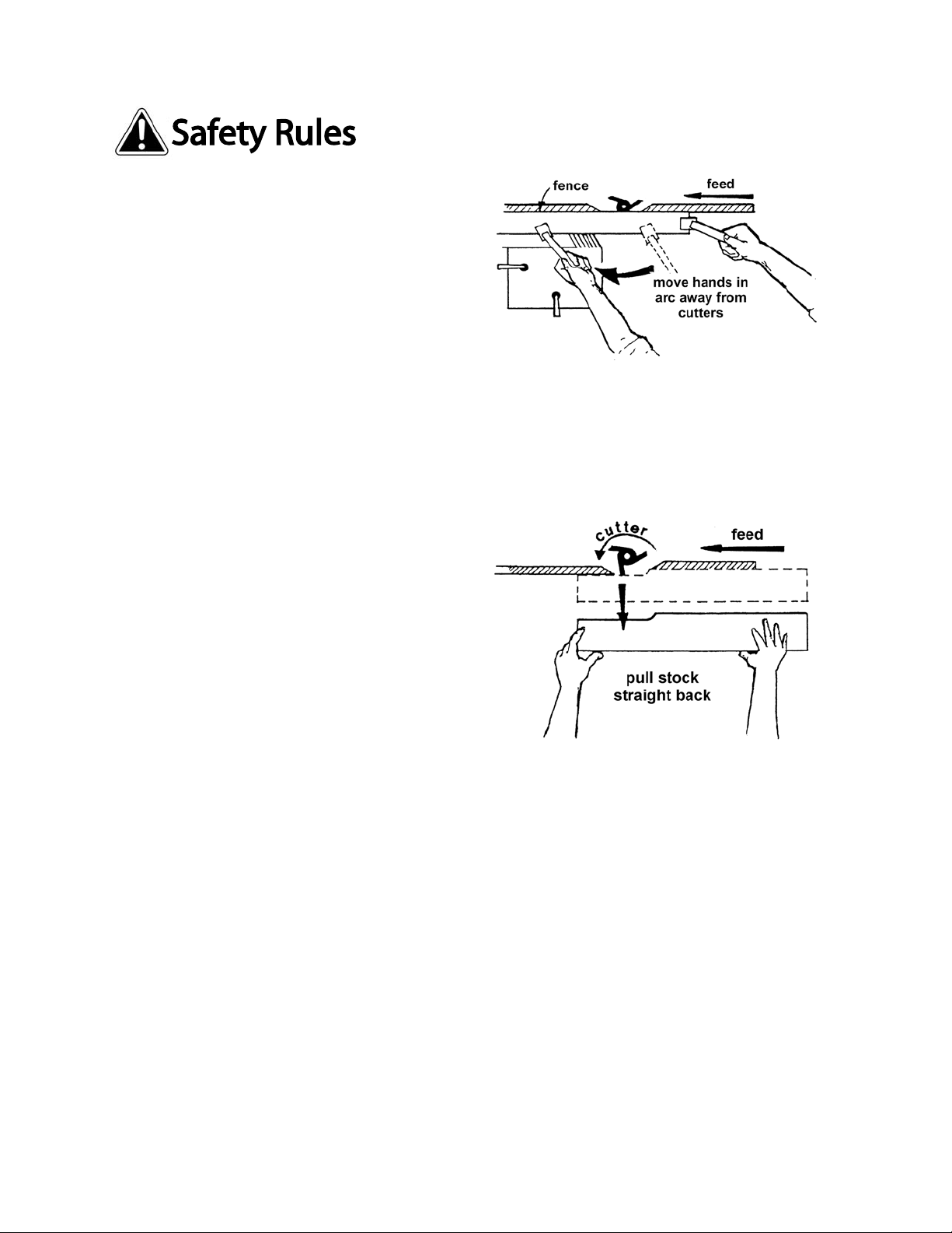
Hand safety – Never pass the hands directly
over, or in front of, the c utters (Figure A). As one
hand approaches the 12 i nch radius point , remove
it (or the push stick) in an arc motion and
reposition hands 12 i nc hes beyond t he c utters.
Blind cut – W hen blind cutting, t he workpiece is
positioned on t op of the template. This keeps the
cutter(s) cutting only the underside of the
workpiece and prov ides a "distanc e" guard f or the
operator.
Cutter Clearance – W ith the power disconnect ed,
always rotate the spindle by hand with any new
set-up to ensure pr oper c learance wit h the cutters.
At the same tim e, check to be sure the c utt erhead
is turning in the cor r ect dir ec tion.
Stock feed – Feed stock opposi te to the di recti on
of the cut ter rot ation (Figur e B). Nev er back stock
out of the cutter once the cut has been started.
Instead, pull the stock straight out away from
cutter and begin the cut again.
Guide pin – Whenever possibl e, use a guide pin
when performing pattern shaping and collar
shaping operations.
Tool maintenance – Cl ean and sharp tools giv e
safer and better performance. Dull tools can
cause kickbacks and excessive chatter. Before
making a cut, always check the condition and
adjustment of the tools. Never use a tool that is
not balanced and rated for the selected RPM.
Spindle speed – Do not o perate tools at speeds
higher than rated by the manufacturer.
Cutter selection – Use only those cutters
designed to be used on the m achine, and mount
only safety type c utt er s on the spi ndle.
Stock condition – The danger of kicked-back
stock can occur when the stock ha s knots, hole s,
or foreign objec ts such as nails. Warped or in-wind
stock should f ir st be joi nt ed on one surf ac e bef ore
attempting to use it on the shaper.
Figure A
Figure B
6
Page 7

Introduction
This manual is provided by Powermati c covering the safe operat ion and maintenance pr ocedures for a
Powermati c Model PM 2700 Shaper. This m anual contains i nstruct i ons on instal lati on, saf ety pr ecautions,
general operating procedures, maintenance instructions and parts breakd own. This machine has been
designed and constructed to provide years of trouble free operation if used in accordance with
instructi ons set forth i n this manual . If there are any questions or comm ents, please contact either your
local supplier or Powermatic. Powermati c can also be reached at our web site: www.powermati c .com.
Specifications
Model Number .............................................................................................................................. PM2700
Motor (TEFC Capaci tor Start Induction) Stock Number
3HP, 1 Phase, 230V, 60Hz, 14A .............................................................................................. 1280100C
5HP, 1 Phase, 230V, 60Hz, 22A .............................................................................................. 1280101C
5HP, 3 Phase, 230V/460V-prewir ed 230V (for 460V see Note below), 60Hz, 13/6.5A .............. 1280102C
Table Size (L x W) ....................................................................................................................... 40" x 30"
Table He ight from F loo r .................................................................................................................. 35-1 /2”
Spindle Size (Standard) .................................................................................. 3/4", 1-1/4" Interchangeable
Router Bit Coll et Si z e (Optional) .................................................................................................. 1/4", 1/2"
Spindle Capacity Under Nut:
3/4” Spindle (provided).............................................................................................................. 3-27/64"
1-1/4” Spindle (provi ded) ............................................................................................................ 5-5/32”
1” Spindle (optional accessory) ................................................................................................. 4-59/64”
Spindle Travel ........................................................................................................................................ 4"
Spindle Speeds (RPM) .......................................................................................... 7500, 10000, reversible
Table Opening Diameter .................................................................................................................... 7.33"
Insert Openi ng Diam eters .............................................................................................. 2.55", 4.16", 5.75"
Fence Size (x 2) .................................................................................................... 4-7/8" (H) x 18-3/4" (W)
Dust Collecti on Minimum CFM Required .............................................................................................. 600
Dust Port Diameter ................................................................................................................................. 4”
Overall Dimensions .......................................................................................... 40" (L) x 37" (W) x 45" (H)
Weight ..................................................................................................... 690 lbs (Shipping), 664 lbs (Net)
Note: For 460V operat ion, magnetic switch (Part No. PM2700-114C) m us t be purchased separately and
installed. A qualified elec trician is recommended.
The above specifications were current at the tim e this manual was published, but because of our policy of
continuous im provement, Powerm atic reserves the right t o change specific ations at any time and without
prior notic e, wit hout incurring obligati ons.
Read and understand the entire contents of this manual before attempting
assembly or operat io n! Failure to comply may cause serious inju ry.
7
Page 8
Unpacking
Remove box and wood crating completely from
around shaper. Chec k for shippi ng damage. Report
any damage immediately to your distributor and
shipping agent. Do not discard any shipping
material until the Shaper is assembled and r unning
properly.
Compare the contents of your container with the
parts lists on thi s page to make sure all parts are
intact. Mi ssing parts, if any, should be reported to
your distributor. Read the instruction manual
thoroughly for assembly, maintenance and safety
instructions.
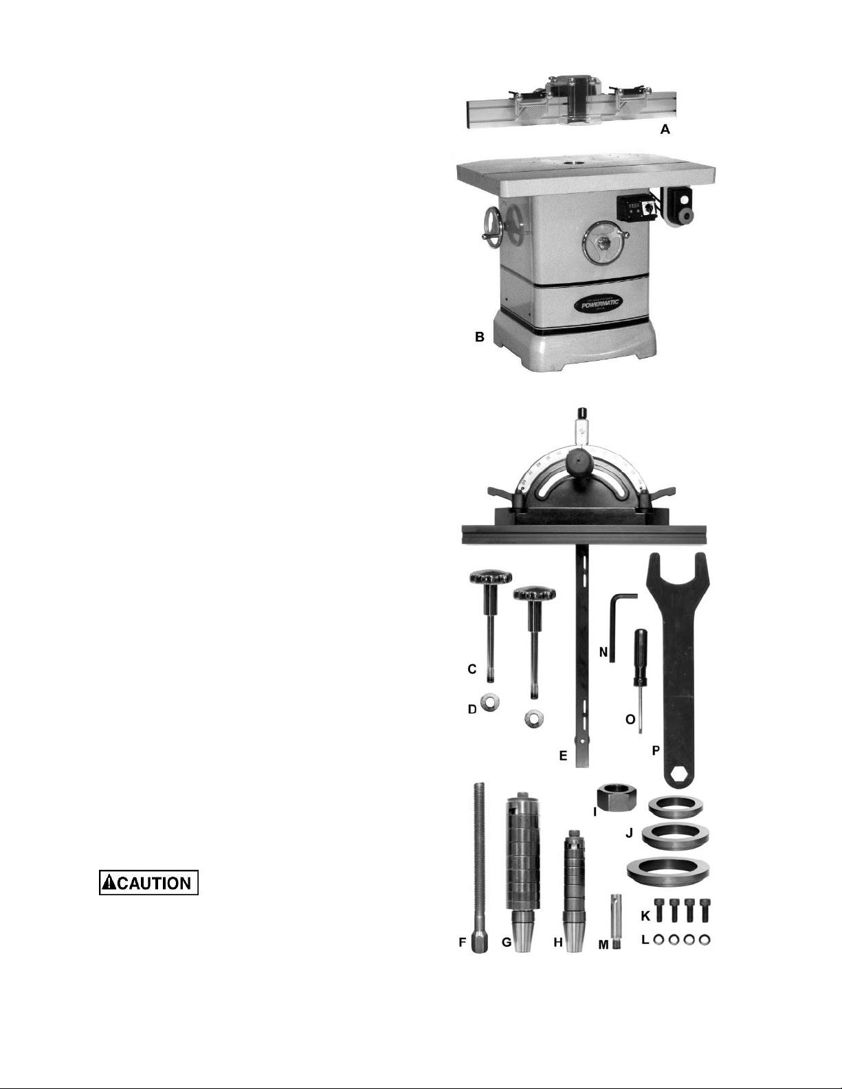
Shipping Contents
Referring to F igur e 1:
Main Shaper Container
1 Fence Assembly (A)
1 Cabinet and Base (B)
Hardware and included tools consist of the
following items:
2 Lock Handle (C)
2 M13 Flat Washer (D)
1 Miter Gauge Assembly ( E)
1 Draw Bar (F)
1 1-1/4" Spi ndle (G)
1 3/4" Spindle ( H)
2 Spindle Nut (I)
3 Insert Rings – 2.55”, 4.16”, 5.75” (J)
4 M10 Socket Head Cap Screw (K)
4 M10 Lock Washer (L)
1 Starting Pin ( M)
1 8 mm Hex Wrench (N)
1 Crosspoint/Flathead Screwdriver (O)
1 Wrench (P)
Main Shaper Container
Installing
1. Unbolt the shaper f r om the skid.
2. Carefully slide the shaper f rom the pallet onto
the floor.
Make sure that the casters do
not get damaged when removing from the skid.
The Shaper should be placed in an area with a
sturdy level floor, good ventilation and sufficient
lighting. Leav e enough space around the m achine
for mounti ng extension wings and r ail assemblies,
and loading and off-loading stock and general
maintenance work.
Hardware
Figure 1
8
Page 9
Cleaning
Exposed met al surfaces, such as the t able top and
extension wings, have been given a protective
coating at t he f actory. This should be rem ov ed wit h
a soft cloth moistened with kerosene. Do not use
acetone, gasoline, or lacquer thinner for this
purpose. Do not u se solvents on pl astic parts, and
do not use an abrasive pad because it may scratc h
the surfaces.
Assembly
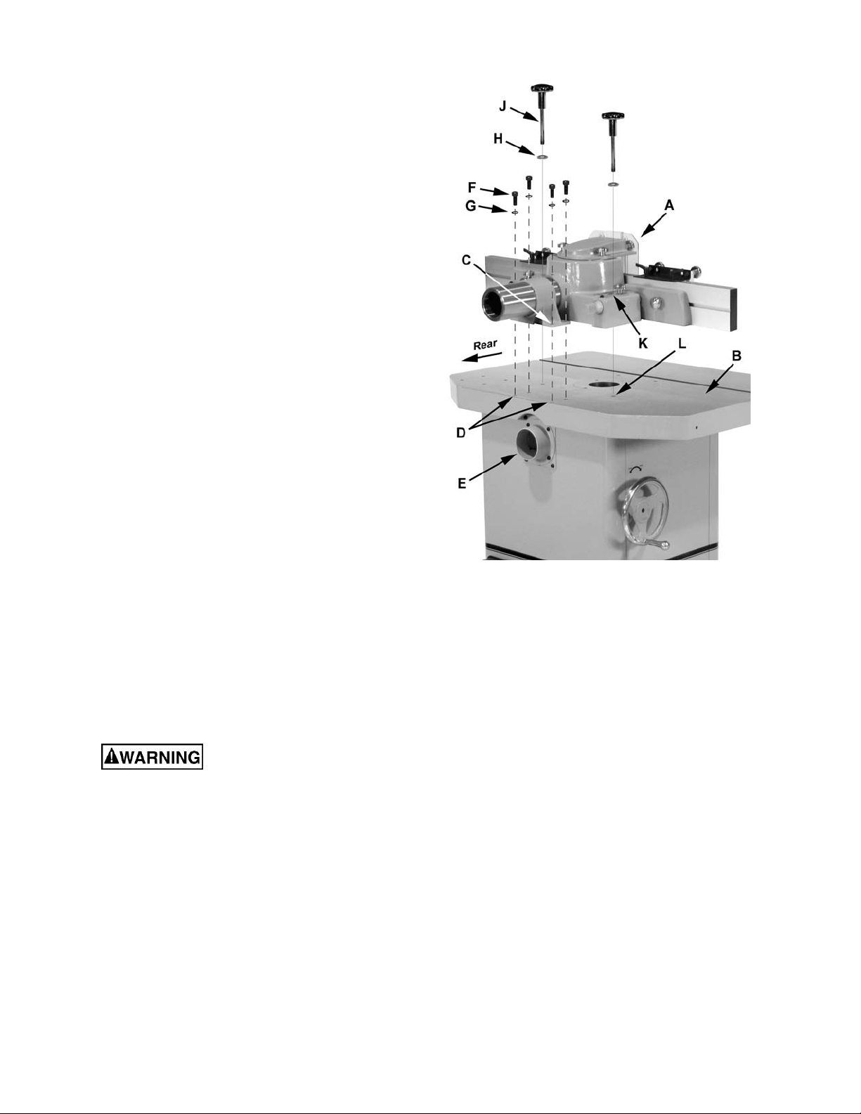
Mounting the Fence
Referring to Fi gur e 2:
1. Place the fence assembly (A) on the table (B),
lining up the four mounting holes (C) on the
bracket with the t hreaded holes (D) on the rear
of the table above the dust port (E).
2. Hand fasten with four each M10 hex socket
cap screws (F) and M10 lock washers (G). Do
not tighten at this time.
3. Place two M13 flat washers (H) on two lock
handles (J). Insert the lock handles through
slots (K) on each side of the base. Partially
thread the lock handles (J) into two mounting
holes (L) on the table. Do not tighten at this
time.
4. Turn the adj ust knob on the br acket to po siti on
the fence all the way to the rear .
5. Tighten the lock handles (J) sufficiently to
prevent the fence from movement.
Electrical Connections
Electrical connections must be
made by a qualified electrician in compliance
with all relevant codes. This machine must be
properly grounded to help prevent electrical
shock and possible fat al injury.
General Information
A power plug is not provided with the Model
PM2700. You may either connect the proper
UL/CSA listed plug or “hardwire” the machine
directly to your electrical panel provided there i s a
disconnect near the machine for the operator.
Consult electrical drawings at the back of this
manual for further clarification of wiri ng setup.
Figure 2
9
Page 10
This machine must be grounded. Grounding
provides a path of least resistance to help divert
current away f rom the operator in case of electrical
malfunction.
Make sure the voltage of your power supply
matches the specif ications on the motor plate of t he
machine.
The PM2700 Shaper should be connected to a
dedicated ci rcuit, and prot ected by a circ uit break er
or time delay fuse, with minimum amp ratings as
shown in Table 1. Local codes take precedence
over recommend ation s.
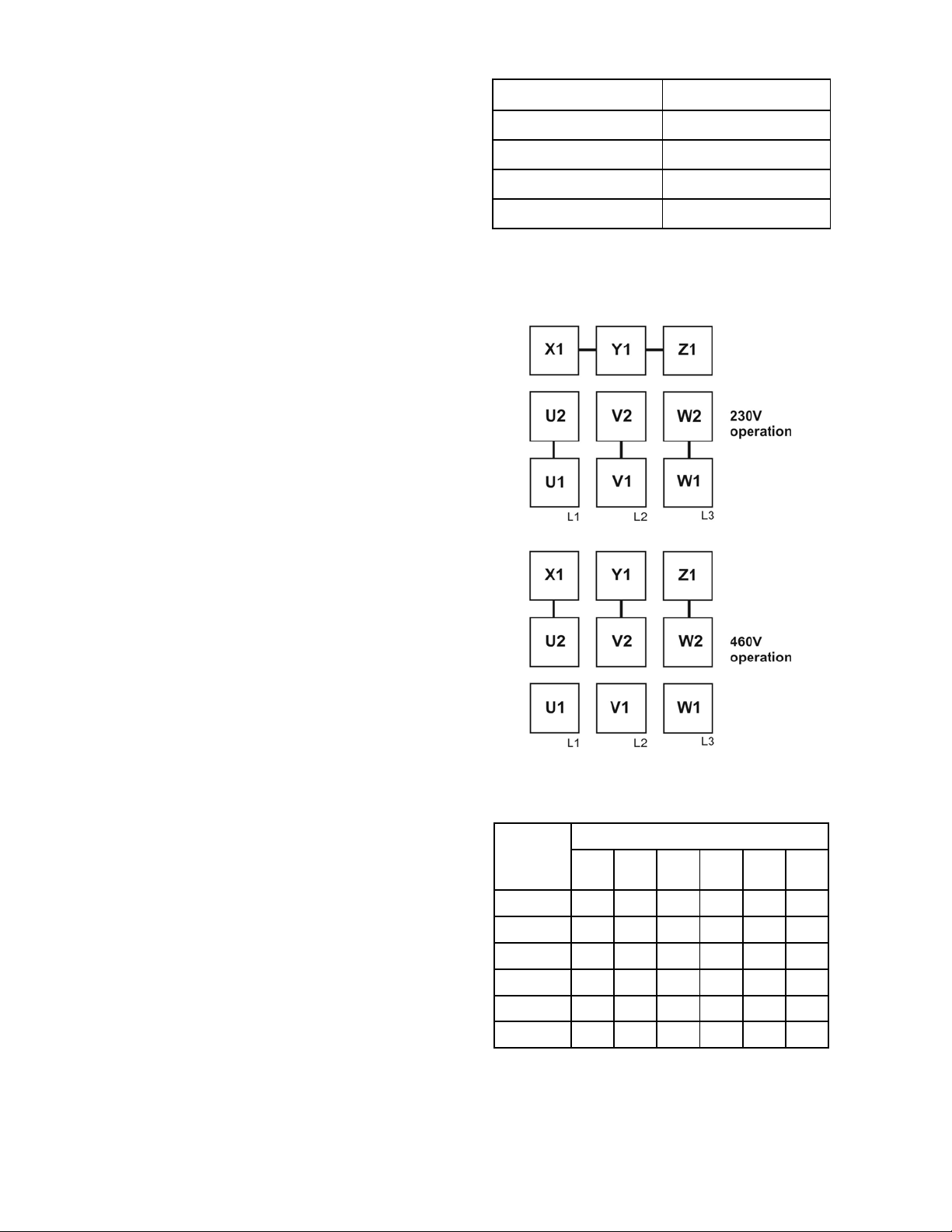
Voltage Conversion (3 Phase Shaper only)
On the 3 phase model, to convert from 230V to
460V, replace the 230V switch with the 460V
switch (not inc luded, order par t no. PM 2700-114C),
and re-wire the incoming leads to the motor as
shown on the diagram inside t he c over of the m otor
junction box. A similar diagram is also i ncluded in
the back of this manual. (Figure 3 shows a
summary of the lead changes for 230V to 460V
conversion.) Note: In case of discrepancies, the
diagram in the motor junction box should take
precedence.
Model Recommended circuit*
1280100C (3 HP 1 PH 23 0V) 30 Amp
1280101C (5HP 1PH 230V) 40 Amp
1280102C (5 HP 3 PH 23 0V) 30 Amp
1280102C (5 HP 3 PH 46 0V) 15 Amp
*subject to local codes
Table 1
Extens ion Cords
The use of ext ension cords is discouraged. Try to
position equipment within reach of the power
source. If an extension cord becomes necessary,
make sure the cord rating is suitable for the
amperage list ed on the machine's m otor plate. An
undersized cord will cause a drop in line voltage
resulting in loss of power and overheating.
The chart i n Table 2 shows the correct size cord to
use based on cord length and motor plate amp
rating. If in doubt, use the nex t heavier gauge. The
smaller the gauge number, the heavier the cord.
Figure 3
Extension Cord Length *
25
50
75
100
150
feet
feet
feet
Amps
< 5 16 16 16 14 12 12
5 to 8 16 16 14 12 10 NR
8 to 12 14 14 12 10 NR NR
12 to 15 12 12 10 10 NR NR
15 to 20 10 10 10 NR NR NR
21 to 30 10 NR NR NR NR NR
*based on limiting the line voltage drop to 5V at 150% of the
rated amp eres.
NR: Not Re commended.
feet
feet
200
feet
Table 2
10
Page 11
Adjustments
When changing tools, making
adjustments, or doing clean-up and
maintenance, always turn the machine off and
unplug the machine from its power source.
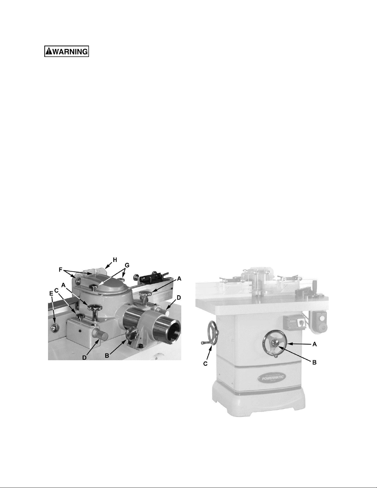
Fence Assembly Movement
Referring to Fi gur e 4:
The adjustm ent contr ols of the f ence assembl y are
as follows:
A – Fence Assembly Lock Knob – to secure fenc e
assembly to table
B – Fence Adjustment Knob – mov es fenc e
assembly forward or back
C – Lock Knob – to secure the infeed and outfeed
fences
D – Infeed/Outf eed Ram Adjust – fine adjustment
for infeed or outfeed fence
E – Lock Knob – loosening permits side to side
adjustment of infeed or outfeed fence
F – Lock Knob – loosening permi ts vertical
adjustment of guar d ( H)
G – Lock Knob – loosening permi ts
backward/for ward adj ustment of guard (H)
Handwheel Adjustments
Referring to Fi gur e 5:
The front handwheel (B) controls the spindle
height.
The side handwheel (C) controls the casters. The
Model PM2700 has a retr ac table caster system that
can be extended to permit t he shaper to be rolled
from one location to another.
Spindle he ig ht
1. Loosen the lock knob (B) on the spindl e height
adjust handwheel (A).
2. Turn the handwheel (A) cloc kwise to raise and
countercl oc k wise to lower the spi ndle.
3. Tighten the lock knob (B).
Caster system adju stment
Retractabl e casters can be ex tended per mi tti ng the
shaper to be moved as follows:
1. Turn the handwheel (C) clockwise to extend
the casters, rai si ng the shaper.
Note: Because of the weight of the machine,
both hands may be needed to turn the
handwheel. Raise the shaper just enough to
permit moving t o another location.
When the shaper has been reposit ioned:
2. Retract the casters by turning the hand-
wheel (C) count er cl oc k wise.
Figure 4
Figure 5
11
Page 12
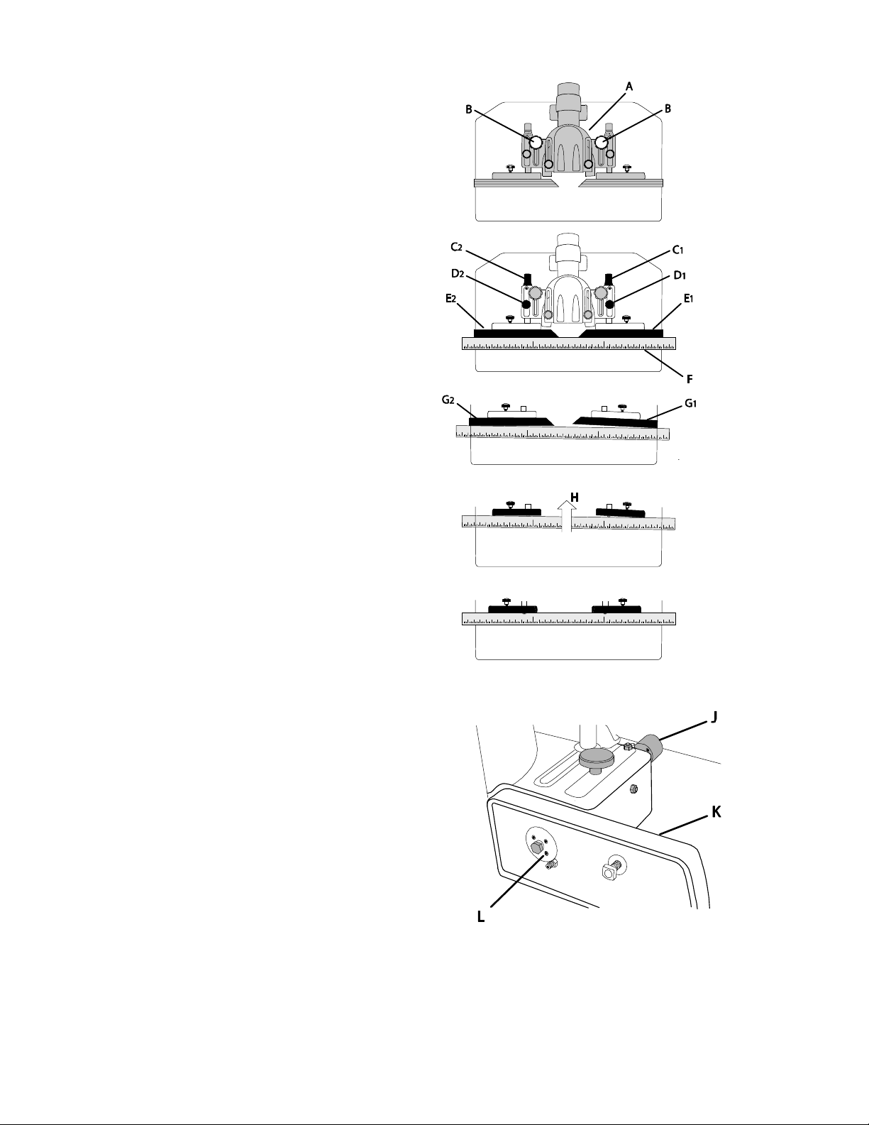
Coplanar Alignment
Follow steps 1–5 to determine if alignment is
necessary. Steps 6–9 will guide you through the
alignment if required.
Verifying that fences are coplanar
1. Remove the guard and spindle attachment.
2. Adjust the fence assembly (A) so it is
positioned approx imately at midpoint and l ock
(B).
3. Place a straightedge (F) on the table pressed
against the infeed (E
4. Unlock the fence lock knobs (D
5. With the ram adjust dials (C
position of either fence as required to bring
both fences in-line (coplanar alignment) using
the straight edge as the point of reference.
No adjustment is requi red if both fences are flush
with the straightedge as shown in Figure 7. Procede to Ram Dial Calibration ( step 00) .
Adjustment is required if the fences appear
skewed (Figure 8). Continue with Coplan ar Adjust-
ment (f ollowing steps).
Coplanar Adjustment
Determine whic h fence i s skewed (in t his ex ample:
, Fig. 8), which will requi re adjustment while the
G
1
remaining fence (G
point.
6. Remove both fences and place the straightedge against the infeed and outfeed fence
castings (Fi gur e 9) .
7. Lock the reference fence (D
skewed fence (D
Read step 8 completely before attempting.
) and outfeed fences (E2).
1
, D2).
1
, C2) adjust the
1
) will serve as the reference
2
) and unlock the
2
).
1
Figure 6
Figure 7
Figure 8
Figure 9
Figure 10
8. Maintain steady pressure of the straightedge
against the fence castings (H, Fig. 9). At the
same time, attempt to bring both fences into
alignment as shown in Figure 10. This is
accomplished by al ternately making incremental adjustments to four setscrews (L, Fig. 11)
on the front f ace of the casting (K, Fig. 11) wit h
a 2mm hex wrench, followed by repositioning
the casting with the micro adjust dial (J, Fig.
11) as required.
Important: It is recommended that the
adjustment setscrews (K, Fi g. 11) be rotat ed in
1/16th increments or less at a time.
Alignment is complete when the skewed and
reference fence castings are coplanar (in-line) as
shown in Figure 10.
9. Replace both fences and secure.
Figure 11
12
Page 13
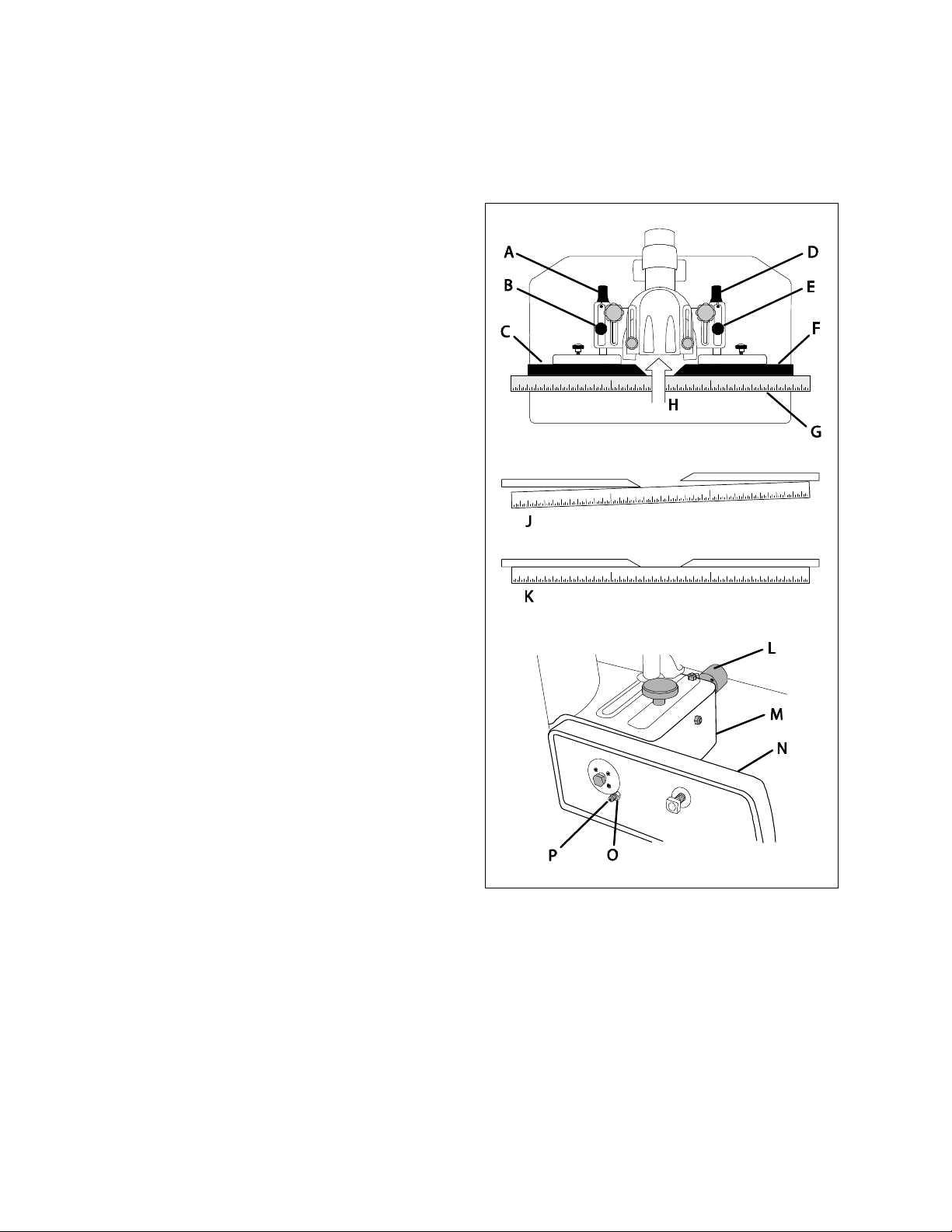
Ram Dial Calibration
The guard and spindle shoul d be r em ov ed.
Referring to Fi gur e 12:
1. Loosen the infeed fence lock knob (E), then
turn the infeed ram dial (D) countercl ockwise to
bring the inf eed fence ( F) bac k al l t he way unti l
the limiter setscrew (P) touches the head
casting (M). Then retighten the lock knob (E).
2. If necessary, loosen two setscrews on the
infeed ram dial (D) with a 2mm hex wrench and
align the zero on the dial with the indicator
mark. Then tighten the setscrews.
3. Next, loosen the outfeed fence lock knob (B)
and turn the outfeed ram dial (A) counterclockwise to bri ng t he outfeed fenc e (C) all the
way back.
4. Place a straightedge (G) on the table against
both fences.
If both fences are flush with the straightedge (K)
and the outfeed ram dial (A) indicates zero, no
further action is necessary.
If alignment is necessary ( J ) :
5. Slide the outfeed fence (C) a side to reveal the
limiting setscr ew (P) on the fence casting (N).
6. Loosen the hex locking nut (O) with a 10mm
wrench and back out the limiting setscrew (P)
with a 3mm hex wrench to permit a sufficient
backward and f or ward adjustment r ange for the
outfeed fence (C).
7. Slide the outfeed fence (C) back onto the
casting and secure.
8. Loosen the out feed fence lock knob (B).
9. While maintaining pressure (H) on the
straightedge (G) against the fences (C, F),
adjust the outfeed ram dial (A) until bot h fences
are in-li ne (K).
After proper alignm ent is made:
10. Slide the outfeed fence (C) aside again.
11. Turn the limiting setscrew (P ) in (t urn cw) until
it comes in contact with the head casting (M)
12. Tighten the hex locking nut (O) with a 10mm
wrench w hile maintain ing the sets crew posit ion
with the 3mm hex wrench.
13. Replace the outf eed fence and secure.
14. Loosen the t wo set-screws (2mm hex wrench)
on the outfeed ram dial (A) and align t he zero
on the dial with the indicator mark. Then tighten
the setscrews.
Infeed side fence casting
-- Outfeed side is mirror image
Figure 12
13
Page 14
Spindle Gib Adjustment
Referring to Fi gur e 13:
The spindle housin g gib on your m ac hine i s f actory
adjusted and initially should not require readjustment. After a period of use the gib may wear and
become loose, introducing play and potentially
causing the spindle (A) to vibrate. This requires
adjustment.
To adjust (refer to Figure 13):
1. With a 12m m wrench, l oosen four jam nut s (B)
that secure the gib sets crew s (C).
2. With a 4mm hex wrench, tighten each setscrew
1/8 or less turn starting with the lowest one,
followed by the uppermost one, then the two
middle setscr ews.
If this is not enough t o remove the table play,
repeat this step unt il the play is removed.
Note: If the gi bs are too tight the front handwheel
(A, Fig. 3) that controls the spindle height will be
difficult to turn.
3. When adjustment is complete, hold the set-
screws (C) in position with the 4mm hex
wrench to mai ntain the setting while tighteni ng
the jam nuts (B) with the 12mm wrench.
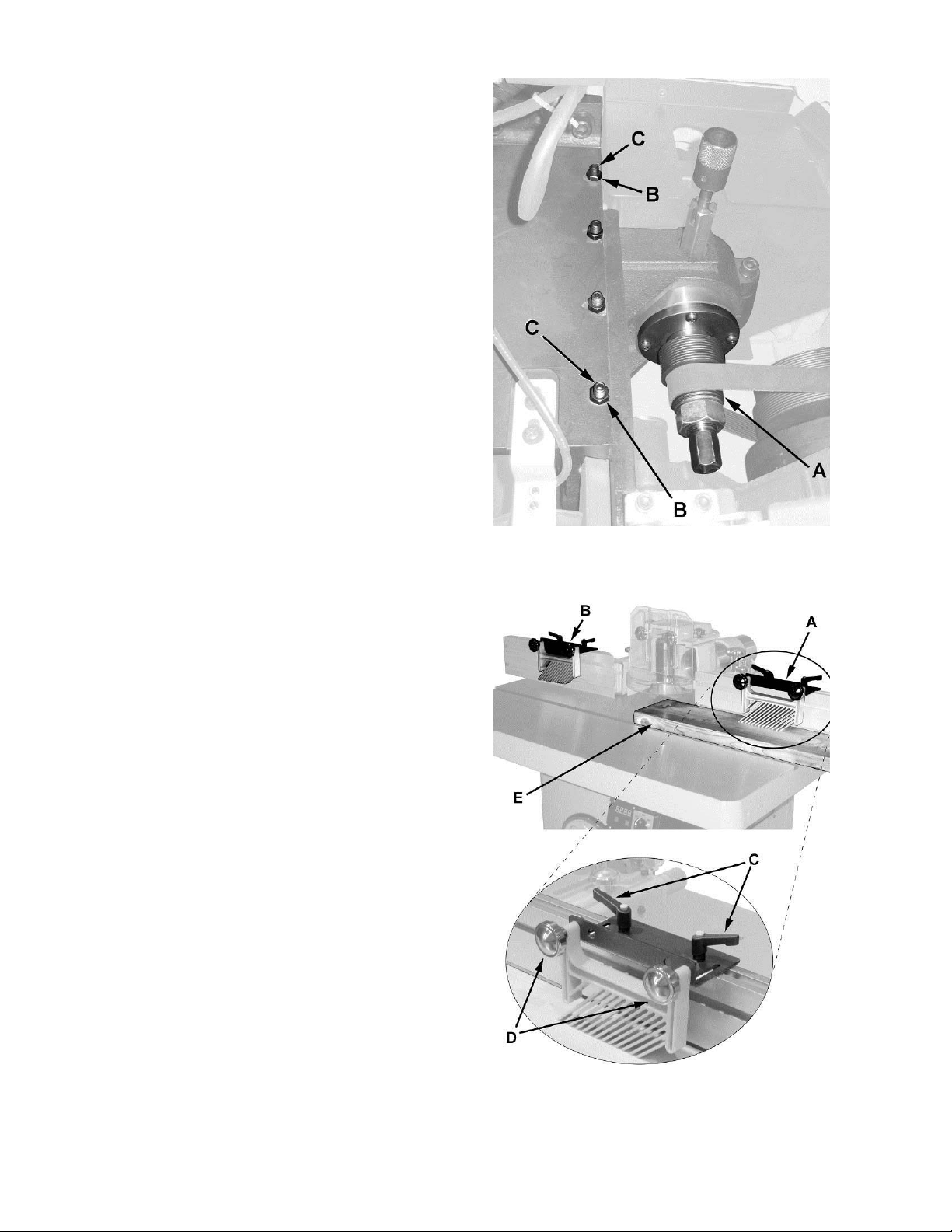
Featherboard Hold-downs
Referring to Fi gur e 14:
The PM2700 Shaper comes equipped with two
featherboard hold-downs (A, B) mounted on the
infeed and outf eed fenc es.
1. Loosen lock handles (C) and lock knobs (D).
2. Slide the hold-down guides to the desired
position along the fence and tighten the lock
handles (C).
3. Place the workpiece (E) on the table against
the fence and under t he hold- down guide (A).
4. Adjust the featherboard stay to put moderate
pressure on the workpiece, then tighten the
lock knob (D).
Figure 13
Figure 14
14
Page 15
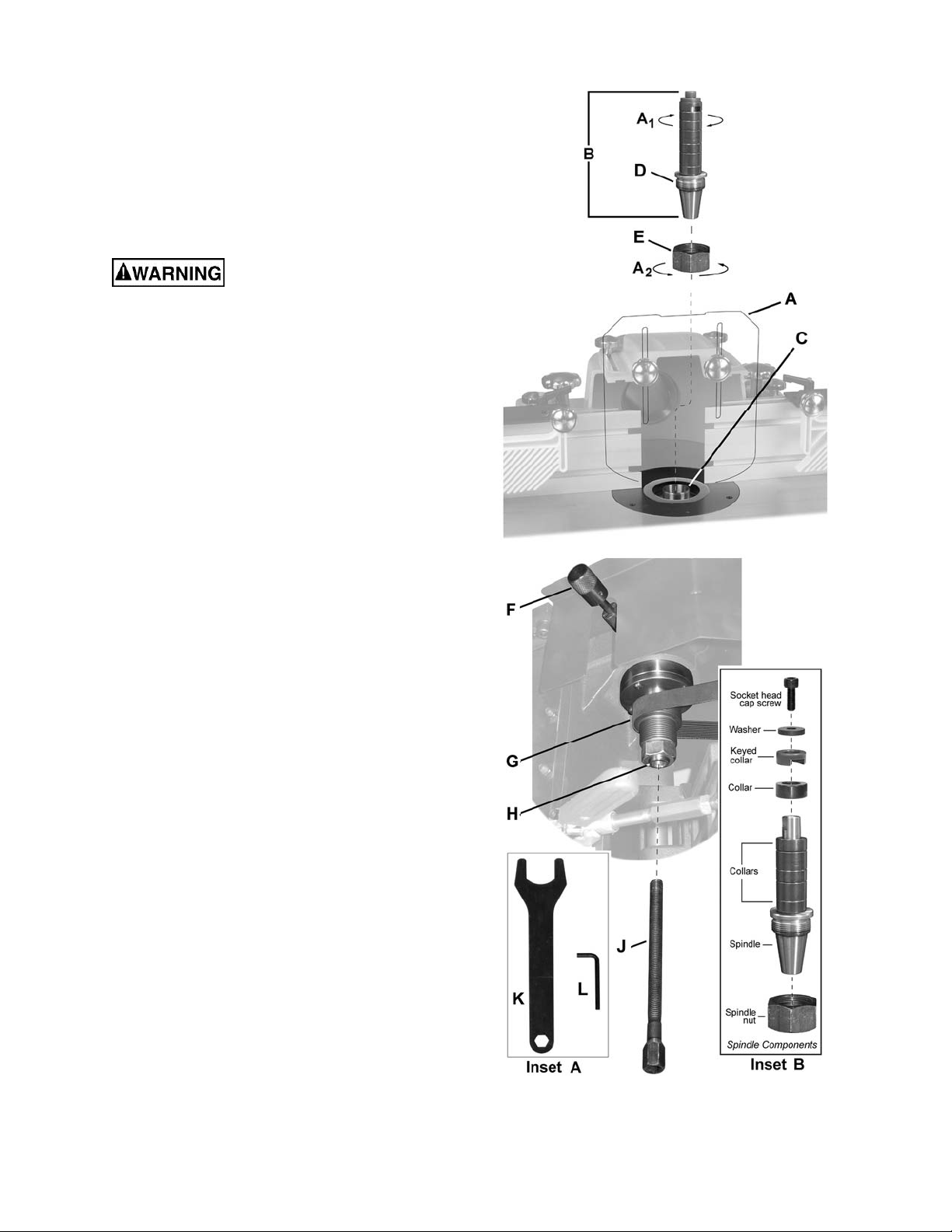
Spindle Assembly Installation
Refer to Figur e 15. The fence guard (A) has bee n
removed for clarity.
The spindle assembly (B) is mounted t o the arbor
(C) and secured with a draw bar (J) and nut (E).
Use the following procedure to install the spindle
assembly. Reverse the order to remove the
spindle.
When changing tools, making
adjustments, or doing clean-up and maintenance, always t urn the machine off and unplug
the machine from its power source.
1. Raise the arbor (C) all the way using the
handwheel located on the front of the cabinet.
Locking the Arbor
2. Locate the spindle lock (F) acc essible through
the door on the right side of the cabi net. Pull
out and rotate 90º right or left, resetting the
knob into the indent.
Turn the arbor ( C) by hand until it locks, then
verify that it will not rotate.
Installing the Spindle Assem bly
3. Thread the nut (E) onto the threaded end of t he
spindle (D) in t he direction indi cated by arrows
, A2). Tighten securely by hand.
(A
1
4. Thread the spindle assembly (B) and nut (E)
onto the arbor (C) and hand tighten only.
5. Insert the draw bar ( J) through the opening in
the shaft (H) just below the drive belt (G ). Turn
clockwise, fastening and securing it to the
spindle. Tighten the draw bar (J) with the
provided wrench (K).
6. Tighten the nut (E) with the wrench (K).
Shaper Cutter installation is described in the
following section. Note that at this time the
spindle holder i s still locked.
Spindle Assembly Removal
Referring to Fi gur e 15:
The spindle hol der must be locked as descri bed in
Spindle Assembly Installation, step 2.
1. Remove the dr aw bar (J).
2. Loosen the nut (E) then, using the wrench (K)
continue to turn until the spindle attachment
breaks free of the ar bor .
Figure 15
15
Page 16
Shaper Cutter Installation
Note: Spindle installation is described in the
previous section.
When changing tools, making
adjustments, or doing clean-up and maintenance, always t urn the machine off and unplug
the machine from its power source.
Locking the Spindle
1. Locate the spindle lock (F, Fig. 15) accessible
through the door on the right side of the
cabinet. Pull out and rotate 90º right or left,
resetting the knob into the indent.
Attempt to turn the spindle (B, Fig. 15) by hand
to verify that it is l oc k ed and will not rotate.
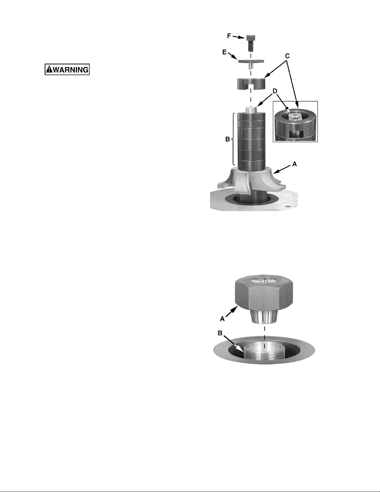
Installing the Shaper Cut ter
Referring to Fi gur e 16:
1. Place the shaper cutter (A) ( not incl uded) ont o
the spindle, ori ented in the proper direction.
2. Place the spacers (B) and keyed collar (C) onto
the spindle.
Note: Spacers come in several widths and the
stacked select i on (B) must be such that the t op
of the keyed collar (C) sits slightly above the
top of the spindle (D ) . This will ensure suffici ent
pressure to properly secure the shaper cutter
(A) when install ation is complete.
3. Install the pronged w as her ( E ) and s oc k et head
cap screw ( F). Tighten screw with t he 8mm hex
wrench provided.
Unlocking the Spindle
4. Pull out the spindle lock (F , Fig. 15) acc essible
through the door on the right side of the
cabinet. Rotate 90º right or left, resetting the
knob into the indent.
Using gloves to prevent injury from the
shaper cutter , turn the spindle (B) by hand to
verify that it turns freely.
Router Collet (Optional) Installation
1. Locate the spindle lock (F, Fig. 15) accessible
through the door on the right side of the
cabinet. Pull out and rotate 90º right or left,
resetting the knob into the indent.
Attempt to turn the spindle (B, Fig. 15) by hand
to verify that it is l oc k ed and will not rotate.
2. Place the router collet (A, Fig. 17) onto the
spindle (B, Fig. 17) and secure with the
wrench (K, Fig. 15) provided.
Figure 16
Figure 17
3. Unlock t he spindle by pulli ng out the lock knob
(F, Fig. 15) accessibl e through t he door on t he
right side of the cabi net. Rotate 90º right or left,
resetting the knob into the indent.
Turn the router collet (A, Fig. 17) by hand to
verify that it turns freely.
16
Page 17

Changing Cutter Speed
Referring to Fi gur e 18:
The Model PM2700 Shaper is equipped with
pulleys that all ow you to change the spindl e speed.
The belt (B) placed on t he upper pull eys (as shown
in Figure 16) provides 7,500 RPM spindle speed.
Placing the belt on the lower pulleys provides
10,000 RPM spindl e speed.
To change speed (ref er to Fi gur e 16):
1. Disconnect the machine from the power
source.
2. Open the door of the cabinet.
3. Remove the belt tension by moving the belt
tension handle (A) to the unlock ( left) position.
This allows the motor (E) to swivel on its
mounting hinge.
4. Move the drive belt (B) to the other set of
grooves (C).
5. Lock the belt tension handle (A), securing the
motor (E) and placing tension on the drive
belt (C).
Drive Belt Tension
Referring to Fi gur e 18:
The drive belt should have sufficient tension to
prevent sli ppage when the machine i s in operation.
If the tension on t he belt needs adjustment:
1. Disconnect the machine from the power
source.
2. Open the door of the cabinet.
3. With a 17mm wrench, loosen the lock nut (G)
on the belt tension assembl y (refer to inset for
loosening dir ec tion).
4. Adjust the hex bushing (F) with a 17mm
wrench (refer t o inset for adj ustment direction)
for proper tension on the belt (B). The tension
handle (A) must be in the lock ed posi tion (ri ght)
while performi ng this step.
Note: Two 17mm wrenches are required for the
next step.
5. Maintain the position of the hex bushing (F)
with one wrench while tightening the lock
nut (G) with the ot her .
Figure 18
Belt Replacement
Referring to Fi gur e 18:
Replace the drive belt (B) as follows:
1. Disconnect the machine from the power
source.
2. Open the door of the cabinet.
3. Remove the belt tension by moving the belt
tension handle (A ) to the unlock (left ) position.
This allows the motor (E) to swivel on its
mounting hinge.
4. Work the drive belt down all the way past the
pulleys.
5. Continue slidi ng the belt down on t he left side
until it is free from the spindle (C), t hen remove
the belt over the top of t he motor pulley (D).
6. Install the new belt by f ollowing these steps in
reverse.
17
Page 18

Precision Miter Gauge
Setting the miter gauge angle
Referring to Fi gur e 19:
The precision miter gauge has a rack and pinion
adjustment f or setting the angle. To operate:
1. Slide the miter gauge i nto one of the slot s on
the table top.
2. Loosen lock handle (A).
To adjust the body (B) of the miter gauge to the
desired angle:
3. Pull the spring-loaded knob (C) out and turn
until the body ( B) of the miter gauge i s at the
desired angle as indicated on the scale.
4. Tighten the lock handle (A).
Indent settings
There are indent s at the 0º, 30º and 45º right and
left positions. At these settings, release the
knob ( C) to engage the stop rod. Then tighten the
lock handle (A).
Note: Do not rely solely on the indents for an
accurate setti ng. After the stop r od engages at the
0º, 30º and 45º po sitions, make a fi ne adjustment
with the knob (C), if necessary, setting it against
the scale indic ator.
Extension plate
The extension plat e (D) can be adj usted by slidi ng
to the right or left or r em ov ed entirely.
To adjust – loosen two lock handles (E), position
the extension plate and tighten the lock handles.
Figure 19
To remove – slide the extension plate completely
off and rem ove the l ock handles (E) and m ounting
hardware.
Calibratin g the mi t er gauge
1. Place the m iter gauge in one of the slots (H) on
the table top.
2. Set the miter gauge to 90º (0º setting on the
scale) by loosening the lock handle (A), then
pulling the spring-loaded knob (C) out and
turning the body (B) unti l 0º i s indicat ed on th e
scale (F).
3. Measure t he accurac y of the gauge agai nst the
slot with a combination square.
If adjustm ent is necessary:
4. Adjust the body (B) until it is perfectly square
(90º) to the miter slot (H).
5. Tighten the lock handle (A).
Verify that the scale indicator (G ) reads 0º. If further
adjustment is necessary:
6. Loosen the screw (F) and adjust the
indicator (G) until it reads 0º
7. Tighten the screw (F).
The mit er gauge should fit snugly within t he miter
slot while still sliding easily. The bar of the miter
gauge has t wo slot s, each wit h a set scre w. Rot ate
one or both of these set screws with a hex wrench
as needed to eliminat e any play between the miter
gauge bar and miter slot .
18
Page 19

Operating Controls
Start/Stop
Power Indicator Light – The start switch has a
power indicator lamp which is on whenever
there is power connected to the shaper, not
just when the shaper i s running. Do not assume
that no light means there is no power to the
machine. If the bulb is bad, there will be no
indication. Always check before use.
magnetic, t he lock can be removed to make the
machine inoper able and can be hidden f or safe
storage by attaching it underneath the rail or
another magnetic surface.
When using the shaper, place the key on the
switch cov er lining up the arrow on the key with
the REMOVE arrow on the cover. Then rotate
the key so the arrow lines up with the LOCK
arrow. This will prevent the safety key from
coming loose f rom vibration when the machine
is in use.
Do not rely that no light
means no power to the machine. Always
check for po wer first. F ailure to co mply may
cause serious inj ury!
Referring to Fi gur e 20:
Start – Press the green start switch (see Note).
When power is connected to the machine, the
green light is always on regardless of whether
the shaper is running or not.
Note: In addition, the switch on the digital
readout must be set t o forward (or rev erse) and
the cabinet door must be closed.
Stop – Press the red switch to stop.
Reset – In the event that the shaper stops
without pre ssing the stop but ton, a s the r esul t of
a tripped fuse or ci rcuit br eak er , etc.:
1. Press red button to reset
2. Press the green button to restart the
machine.
Digital Readout
The digital readout (Figure 21) is used for
making incremental spindle height adjustments
where applicable, if multiple shaping/cutting
passes are to be performed on a given workpiece.
Set the digital r eadout as follows:
1. Set the desired spindle height for the
workpiece to be cut .
2. Supply power to the machine so the digital
display is lit.
3. Select inch or mm by momentarily
depressing the button on the right.
4. Press the 0" SET button for approximately
two seconds.
The digit al display resets to zero, which is your
reference point. When the spindle is raised or
lowered (fr ont handwheel), the change is relative
to this reference.
Figure 20
Safety Key
The start/stop switch on the Model PM2700
comes equipped with a magnetic safety key.
When in place on t he switch as shown in Figur e
20 the magnetic safety key trips a relay which
will allow the machine to start and stop when the
respective switches are pressed. Being
If this feature is used, the display should be
reset to zero for each new cutt ing operation.
Figure 21
19
Page 20

Operations
Overview
Before applyi ng power to the machine, Check t he
motor and switch wiring diagrams for proper
voltage connections. Check that all mounting
screws and bolts are tight.
Turn on the motor mom entarily to check for proper
rotation. The spindle should rotate counterclockwise when looki ng down on the spindle. Correc t as
required.
Run the machine for a short period of time to
ensure that the movi ng parts are working properly
with no excessiv e vibration. If a probl em develops,
correct it before turning t he shaper over for general
use.
Safety Devices
Safety devic es such as guards, fixtures, t emplates
hold-downs, push sticks (Figure 22), feather
boards and power feeders should be used
whenever possibl e. Figure 22 shows a push sti ck
which can be easily m ade from scrap wood.
Note: For the sake of clarit y, the shaper guard ha s
been omitted from most illustrations. All shaper
operations m ust be done with the proper guar d in
place and any other device which insures the
safety of the oper ator.
Deep cuts require excessive
horsepower and pushing force to control the
cut.
Deep cuts can also cause the wood to splinter or
split and may lead to lost c ontrol or personal i njury.
Preband shaper the stock whenever possible to
1/16 inch of finished size. When an edge finish is
unsatisfact ory, take two or more cuts with t he final
cut no more than 1/16 inch deep.
In the case of shaping acro ss the gr ain, t he trail ing
board edge will often splinter. To correct this, the
best solution i s to make the board 1/4 inch ov ersiz e
in width, shape the board, and sim ply trim off the
excess.
Cutter Rotation
Counterclockw ise Setup – With the cutter install ed
as shown in Figure 23, feed the workpiece from
right to left.
Grain Direction Considerations
Plan to shape the workpi ece in the same direct ion
as the grain when possible. Some open grain
woods (such as redwood, fi r and oak) will leave a
rough, or sli ghtly spl intered edge when c ut against
the grain.
Figure 22
Figure 23
Clockwise Setup – With the cutter installed as
shown in Fi gure 24, feed t he workpiece f rom left to
right.
Figure 24
20
Page 21

Using the Fence
Using the fence is the saf est and most satisfact ory
method of shaping, and should always be used
when the work permits. Almost all straight work
can be used with the fence.
For average work, where a porti on of the original
edge of the work is not to be touched by the cutter,
both the front and rear fences are set in a str aight
line as shown in Figur e 25.
When the shaping operation removes the entire
edge of the work, e.g. in jointing or making a full
bead, the shaped edge will not be supported by
the outfeed fence when both fences are in line,
Figure 26. In this case, the stock should be
advanced to the position shown in Figure 26 and
stopped. Turn off the machine and move the
outfeed fence forward to contact the workpiece,
Figure 27. Remove the workpiec e, start t he mot or,
and then continue the oper ation.
Always remove workpiece
before starting the machine! This will prevent
kickback and potential serious injury.
Figure 25
Figure 26
Figure 27
21
Page 22

"Z" Dimension
Before making a template (or using the edge of the
workpiece) for shaper cutting, the "Z" dimension
must be established in order to determine the
shape and size of the finished stock. The "Z"
dimension is t he diff erence between the i nnerm ost
part of the c utter edge and the outsi de diameter of
the ball beari ng follower (collar). See Figure 28.
Note: The "Z" dim ension can be either positive or
negative.
The "Z" dim ension is positiv e if the cutt er is larger
than the coll ar bearing.
The "Z" dimension is negative if the cutter is
smaller than the c ollar bear ing.
Depth of Cut
The depth of cut is the distance from the outside
circumference edge of the collar (which the work
rides against) t o the outside edge of the cutter. The
depth of cut is determined by the position of the
fence rel ative to the cutt erhead and/or by the u se
of shaper coll ar s (see Figure 29).
Straight Edge Shaping
Straight edge shaping is always performed with the
workpiece again st the fence. Use only push sti cks
and hold downs to keep the workpi ec e on posi tion.
Do not use a miter gauge to
feed material along the fence face. The workpiece can bind and cause kickback. Failure to
comply may cause seriou s injury!
To set up:
1. Disconnect or unplug the machine from its
power source.
2. Check to see t hat the f ence f aces are paral lel,
properly in line or offset if necessary, and
securely tightened.
3. Rotate the cutt er s and i nspect for clearance.
4. Lock the spindl e.
5. Install all nec essary guards.
6. Reconnect power to the mac hine.
7. Take a tri al cut on a piece of scrap the same
thickness as workpiece.
Note: Only a short cut i s necessary t o determ ine if
the profile, depth, and height of cut is correct.
Figure 28
Figure 29
22
Page 23

Edge Shaping
When edge shaping, never attempt t o hand guide
any stock less than 12 inches long, or narrower
than 3 inches wit hout t he use of a special gui de as
shown in Figure 30.
When edge shaping, the work-
piece must b e at least 12 inch es long unless a
special guide is used.
1. Use the hol d-ins and hold-do wns as shown in
Figure 30 to firmly hold the workpiece down
and against the f ence. If workpiece i s too wide
for the hold-ins to be used, clamp a scrap
board to the table to substitute for the hold-i ns.
2. Check the rotation of the cutter. Be sure to
feed workpiec e against rotation of the cutter.
Figure 30
3. Feed the workpiece slowly and steadily with
firm, even pressure to m ak e a smooth cut.
Important: The rate of feed depends on de pth of
cut and experi enc e of operator.
End Shaping
When end shaping narrow stock, it is important
that at least one half of the workpiece end be in
contact with either the in-feed or out-feed fence.
Use a guide similar to t he one shown in Figure 31
which tightly clamps the scrap piece to the workpiece and provides the necessary width.
End shaping a narrow workpiece without a special guide could result in
the workpiece rocking into the cutterhead,
causing personal injury.
Shaping All Sides
Because cross grain shaping is more likely to
create chi pping out and splinters on some woods,
it is good practice to first shape the cross-grain
sides. Any chippi ng that does occur is taken care
of by the with-grain cuts, as shown in Figure 32.
On-Edge Shaping
If the shaper fence does not firmly support wide
stock, use the T-slots in the fence to attach a
special rigid high fence as shown in Figure 33.
Figure 31
Figure 32
Note: Be sure the scre w holes are counter sunk in
the special fence to avoid interference with the
workpiece.
Figure 33
23
Page 24

Straight Line Bevel Shaping
To shape a beveled straight edge, use a beveledge shaping jig in combination with the regular
fence as shown in Figur e 34.
Figure 34
To perform a bevel-edge cut, the in-f eed edge of
the jig is placed against the infeed fence and
clamped to the table as shown in Figure 35. The
outfeed fence is moved forward as necessary to
compensate for the cut.
Contour Edge Shaping With Collar Bearing
To shape contoured edge s, the operator m ust first
remove the fenc e assembly .
In order to control the workpiece and limit the
depth-of- cut, the operator m ust use an anti-f riction
collar with the cutt er ( s) as shown in Figure 36.
Figure 36
The collar may be positioned above or below the
cutter(s), and its function is to ride against the
workpiece or tem plate. A t the same tim e, the coll ar
will establish the depth-of-cut as shown in
Figure 37. Whenever possible, al ways use the ring
guard or safety collar.
Figure 35
Never attempt to bevel cut free
hand. Always use a bevel-edg e f ixture.
Note: Since the collar requires at least 1/8" of
surface edge to r ide against, t he entire edge cannot
be shaped as sho wn in Figure 38. The added u se
of a pattern, however, permits the shaping of the
entire contour edge.
Figure 37
Figure 38
24
Page 25

If the workpiece is to be shaped all around the
perimeter , hold it firmly and pu sh the work strai ght
into the cut ter until the depth of cut is established
by the collar as shown in Figure 39. Continue to
feed the work so that the point of contact on the
edge is always 90 degrees to t he collar (or dir ectly
in line with the c utter edge) and held firml y against
it.
When the workpiece is not contoured all around,
start the cut as shown in Figure 45. With this
operation, t he workpiece i s positioned agai nst the
starter pin and the end swung into place to start
the cut. When the cut has begun and the
workpiece f irmly agai nst t he col l ar, swing the stoc k
away from the pin and proceed wit h c ut.
Freehand shaping is extremely
dangerous. The operator must be aware at all
times of the proximity of his hands to the
cutter. Han ds must never come closer th an 12
inches to the cu t t er wi t hou t t he proper guard or
similar safet y devi ce over the cutterhead.
Shaping With Collars
When shaping with coll ars and starting pin, always
adhere to the following rules for good work and
safe operation:
Figure 39
Figure 40
The collar m ust have suffici ent beari ng surface, as
shown in Figure 40. Also, the stock must be f airly
heavy in proporti on to the cut being made. Under
no circumstances should a short, light workpiece
be shaped against the collars, as in Figure 41.
Note: The edge of t he work to be shaped must be
smooth. Any irregul arit y on the surface which ri des
against the coll ar will be duplicated on t he molded
surface.
Collars must be smooth and free from pitch and
other substances.
Position of Collars
Collars may be used above, below or between
cutterheads.
1. When the collar is used below the cutter, as
shown in Figure 42, the progress of the cut c an
be seen throughout the operation. However,
any accident al lif ting of the work will gouge the
wood and ruin the workpi ec e.
2. When the collar is used above the cutter, as
shown in Figure 43, the cut cannot be seen.
But this method offers an advantage i n that the
cut is not affected by slight variations in the
thickness of the stock. Also, accidental lifting of
the workpiece will not gouge the workpiece;
simply repeat the operation to correct the
mistake.
Figure 41
Figure 42
Figure 43
25
Page 26

3. Using the collar between the two cutters has
the adv antages and disadvantages of the first
two procedure s, and is frequentl y used where
both edges of the work are to be molded,
Figure 44.
Note: It is adv isable to place t he cutter as low as
possible on the spi ndle to reduce spindle deflecti on
and ensure the best possible finish. Also make
sure that t he contacting surf aces of the cutter are
smooth, clean and without dents.
Starting Pin
Use of the starting pin should
only be attempted by advanced users. If you
have never used this method, it is
recommended you get training from a qualified
person. Fail ure to co mply may resul t in serious
injury.
The starti ng pin is used to support the work when
starting t he c ut.
1. The work should be placed in the position 1,
(Figure 45), usi ng the starting pin as a support
2. Swing the work into t he cutter as shown in t he
position 2. The work is no w supported by t he
starting pin and the collar.
3. After the cut has been started, the work is
swung free of the starting pin and only rides
against the collar (Figure 46). Always feed
against the cut terhead rotation.
Figure 44
Figure 45
Figure 46
26
Page 27

Arcs and Circles
Large circular and arc-shaped stock can be
shaped as descri bed in Contour Edge Sh aping on
page 24. However, sm aller sized stock requires the
use of special shaping jigs similar to t hose shown
in Figure 47.
With the ent ire fence assem bly remov ed, carefully
position the jig for desired depth-of-cut and
securely clamp to the table.
It is important with the arc and circle shapes that
the workpiece, prior to being shaped, must be
roughly cut to the desired size and curve of the
finished piece. Make sure that the jig curve
matches exactl y the workpiece curv e. At all times
keep the workpiece firmly in contact with the jig
while the cutter is cut ting the stock.
Never perform this type
operation without a ring guard, safety collar or
similar safet y devi ce over the cutterhead.
Enclosed Edge Shaping
An enclosed workpiece edge is shaped in the
same manner as an outside contoured edge
except that a starting pin is not required as shown
in Figure 48.
Note: If the whole edge is to be shaped, the
operator must use a patter n.
Figure 47
Position the workpi ece on the table before starti ng
the motor. The operator must do the entire shaping
cut by pushing (feeding) the workpiece into the
cutter(s).
Enclosed edge shaping is
extremely dangerous. The operator must be
aware at all times of the di rect io n of feed. Never
perform this type operation without a ring
guard, safety collar or similar safety device
over the cutterh ead.
With a firm grip, ease the edge into the cutter(s)
until stopped by t he c ollar as shown in Fi gur e 48.
Continue to push straight in while feeding and
turning the workpiece at the sam e time until t he c ut
is finished. T urn off the motor and do not remove
workpiece until the cutters have completely
stopped.
Never perform enclosed edge
shaping if there is less than two inches of
workpiece material all around the opening.
Never perform enclosed edge shaping if the
workpiece op ening is smaller, in an y direction,
than twice the diameter o f th e cut t er( s) .
Figure 48
27
Page 28

Templates
The template must be thick enough to provide a
solid bearing edge against a collar. When
constructi ng a templat e similar to the one shown in
Figure 49, keep in mind that it serves only as a
guide for the cutter.
If the workpiece requires all-around shaping, the
template c an be constructed f rom sev eral sect ions
pieced together as shown in Figure 50.
Securing the Template
There are various methods used to secure the
template to the workpiece. The experienced
operator will choose the most appropriate
according t o the shape, size, and type c onstruct i on
of the template. For example, if the workpiece is
large enough to extend beyond the front of the
table and sti ll l eave r oom for the desir ed cut , it can
be securely held to the tem plate with "C" clamps
as shown in Figure 51.
Figure 49
Figure 50
In many situations the workpiece is positioned
against the template using dowels as anchor
points and handles (wood blocks) to assist the
operator in guidi ng the work-piece through the cut
as shown in Figure 52.
Figure 51
Figure 52
28
Page 29

Special Cuts
The illustrat ions in this section show the prof ile, or
section, views made by the cutter(s). The most
effici ent cutters are carbide ti pped to ensure clean
and long-term cutting. Small cutters may be solid
carbide, and some use inserts. Since there are
such a wide variety of choices, the operator is
limited only by his experience and imaginati on.
Stacked Cutters
A variety of inter esting and timesavi ng cuts can be
made in a single setup by stacking the cutters.
When the operator stacks the cutters, extra care
should be taken to see that all par ts are clean, free
of nicks and flaws, and perfectly balanced in the
stacked positi on.
Sash and Door Shaping
Shaping a door requires two operations.
Figure 53 shows the sash cut for the first
operation.
Figure 54 shows the stock flipped over and the
sash cutter used with a 1/4 inch groove cutter to
complete the cut.
Figure 55 shows the f i rst shaping cut wit h the sash
cutter for t he matc hing door stile sash.
Figure 56 shows the same cut with the stock
flipped ov er.
Figure 57 shows the f irst shaping c ut for a window
sash stile ut ilizing a sash cutter, col lar, and a 1/2
inch groove cutt er .
Figure 53
Figure 54
Figure 55
Figure 56
Figure 57
29
Page 30

Figure 58 shows BOT H cut s required for a window
sash rail end. The f irst operat ion at t op is a rabbet
cut made with a groove cutter. The second
operation is performed with a stub spindle and
buttonhead screw.
Butt Joints
All butt-type joints require both work-pieces to be
perfectly square and straight-edged.
Glue Butt Joint
To perform a glue butt joint, both fences are kept
inline and adj ust ed for a depth of cut (Figure 59).
The cuts on both work-pieces are part-edge cuts
which do not reduce the stock width during the
cutting procedure. When shaping the two
workpieces, one i s f ed t op-side up; the ot her is fed
bottom-side up.
Tongued Joint
Similar to the glue joint, both fences are kept in-line
for the tongued joint and adjusted for a 1/4 inch
depth of-c ut with no reducti on in stock widt h. With
this joint, however, both work-pi eces are fed with
the same side up as shown in Figure 60.
Drop Leaf Joint
When shaping a drop-leaf joint as shown in
Figure 61, the leaf workpiece is shaped with a
Drop-Leaf Bead cutter; the table workpiece is
shaped with a Drop-Leaf Cove cutter.
With this type joint, the whole edge of both
workpieces is shaped, same-side up, and
allowance m ade for a 1/16 i nch reducti on in widt h.
Adjust the in-feed fence to reduce the workpiece
width by 1/16 i nc h, and adjust the out-feed fence to
compensate for stock removed.
Taper Cuts
Taper cuts can be made by offsetting the fences
for the amount of taper desired, or with a layout
line on the stock which can be paralleled to the
infeed fence as shown in Figure 62.
Figure 58
Figure 59
Figure 60
Figure 61
Start the cut by holding the stock against the
infeed fence and swinging it into contact with the
outfeed f ence just past the cut terhead. As the cut
is started, t ransfer pressure to hol d the workpiece
against the outfeed fence, and continue feeding
the workpiece through. After the first cut, the
fences will have to be readjusted in order for the
second cut (parall el cut) and the final depth-of-cut
to remain true with the taper.
Figure 62
Do not use the standard fence
for short work (12 inches or less in length on
the side t o be cut). Instead, use a miter gau ge
or special fixture to avoid l osing control o f the
workpiece.
30
Page 31

Tenoning
The tenoning f ixture ill ustrated in Fi gure 63 shows
a miter gauge equipped with a hold-down for
shaping the ends of narr ow work-piec es.
The miter gauge can also be adapted to cut square
and centered tenons at t he ends of legs for tables,
chairs, etc. S ec ur e the leg t o jig and posi tion for cut
as shown in Figure 64.
Make all first cuts with the same jig setting and
spindle height. When the first series of cuts have
been made, reposition leg on the jig for each
succeeding cut.
Note: If the leg is taper ed, use a wedge to place
the side fac ing the cutt er into a 90 degree vertical
position as shown in Figur e 65.
Figure 63
Figure 64
Figure 65
31
Page 32

Troubleshooting for PM2700 Shaper
Trouble Possible Cause Remedy
Shaper will not star t.
Overload kicks out
frequently.
Cuts are
unsatisfactory.
1. Cord unplugged f rom the power
source.
2. Fuse blown or circuited breaker
tripped.
3. Cord damaged.
4. Reversing switch is in the Off
position.
5. Overload tripped.
6. Cabinet door is open.
1. Extension cord or wiri ng
inadequate size.
2. Feeding stock too fast.
3. Cutter needs cleaning or replacing.
See also Unsatisfactory Cuts
below.
1. Dull cutter.
2. Cutterhead rot ating in wrong
direction.
3. Feeding work in wrong di r ec tion.
4. Gum or pitch on cutter.
5. Gum or pitch on table causi ng
erratic feed.
1. Plug in power cord.
2. Replace fuse or reset circuit
breaker.
3. Replace cord.
4. Turn switch to f orward of r ev erse.
5. Reset overl oad by depressi ng r ed
stop button.
6. Close cabinet door .
1. Replace cord or wiri ng with proper
gauge wire.
2. Reduce feed stock r ate.
3. Clean or replace cutter.
1. Replace cutter.
2. Check for proper r otati on at startup.
3. Feed work against the cutter
rotation.
4. Remove cutter and clean with
solvent.
5. Clean table with solvent.
Cutter does not com e
up to full speed.
Machine vibrates.
Edge splits off on
cross grain cut.
1. Shop wire gauge is too small.
2. Extension cord or wiri ng
inadequate size.
3. Power source is not adequate.
4. Motor not wired for c or r ect v ol tage.
5. Spindle is locked with madrel lever.
1. Stand on uneven surf ac e.
2. Cutterhead damaged.
3. Defective V-belt.
4. V-belt incorrectly tensioned.
5. Bent pulley.
6. Motor mounted improperly.
1. Characteri stic of this type of cut. 1. Make cross grain cuts fir st, then
1. Replace wiri ng with proper gauge
wire.
2. Replace wit adequat e si z e c or d.
3. Contact your elec tric utility.
4. Refer to motor name plac e and
wiring diagram for correct wiring.
5. Unlock spindle – see label next to
lover on base.
1. Stand must rest solidly on level
surface. Fasten to floor if
necessary.
2. Replace cutterhead.
3. Replace V-belt.
4. Apply proper tension.
5. Replace pulley.
6. Motor must be properly m ounted
with snug nuts and bolts.
finish cut wit h the grain. Use scrap
block to support end of c ut.
32
Page 33

Trouble Possible Cause Remedy
Raised areas on
shaped edge.
Work pulled from
hand.
Depth of cut not
uniform.
Work burns.
Cut height not
uniform.
Cuts not smooth.
1. Variation of pressure holding work
against cutt er .
1. Feeding in wrong direc tion. 1. Always feed work against the
1. Fence misalignment.
2. Side pressure not uniform.
1. Cutting too deep on one pass.
2. Forcing work.
1. Variation in pr essure holding work
to table.
1. Wrong R.P.M.
2. Feed too fast.
3. Working against the grain.
4. Cutting too deep on one pass.
1. Hold work firmly against table and
fence. Use hold-downs and pu sh
sticks.
rotation of the cutt er head.
1. Align outfeed fence.
2. Use hold-downs; keep constant
pressure against fence and use
push sticks.
1. On hardwoods take light cuts; attain
full depth wit h sever al passes.
2. Feed work slowly and steadily.
1. Keep pressure uniform throughout
pass. Use hold-downs. Mak e pass
slowly and steadil y . Keep work
under cutter whenev er possible.
1. Use faster speed.
2. Slow feed speed.
3. Work with the grain whenever
possible.
4. Take several passes on ver y deep
cuts.
Spindle does not
raise freely.
1. Shaper dust and dirt in r aisi ng
mechanism.
Optional Accessories
1791205 1" Spindle
1791207 1/4" Collet
1791208 1/2" Collet
1. Brush or blow out loose dust and
dirt.
33
Page 34

Parts
Ordering Replacement Parts
Replacement par ts are li sted on the f ollowing page s. To order parts or reac h our servi ce depar tm ent, call
1-800-274-6848, Monday through Friday (see our website for business hours, www.powermatic.com).
Having the Model Number and Serial Number of your mac hine available when you cal l will allow us to
serve you quickly and accurately.
Table – Parts List
Index No. Part No. Description Size Qty
1 ............... PM2700-101N ..........Insert Ring ..........................................................2.55” I.D. .................... 1
2 ............... PM2700-102N ..........Insert Ring ..........................................................4.16” I.D. .................... 1
3 ............... PM2700-103N ..........Insert Ring ..........................................................5.75” I.D. .................... 1
4 ............... PM2700-104N ..........Table ..................................................................................................... 1
5 ............... PM2700-105 ............Starting Pin ............................................................................................ 1
6 ............... TS-2361061 .............Lock Wash e r ......................................................M6 .............................. 4
7 ............... TS-1503031 .............Socket Head Cap Screw .....................................M6x12 ........................ 4
8 ............... PM2700-108 ............Left Dust Deflector ................................................................................. 1
9 ............... PM2700-109 ............Right Dust Deflector .............................................................................. 1
10 ............. PM2700-110 ............Switch Plate .......................................................................................... 1
11 ............. TS-1550061 .............Fla t Washer ........................................................M8 .............................. 2
12 ............. TS-1504041 .............Socket Head Cap Screw .....................................M8x20 ........................ 2
18 ............. 1791789...................Miter Gauge Assembly (Index #19 thru #39) .......................................... 1
19 ............. PM2000-323 ............Miter Gauge Body.................................................................................. 1
20 ............. PM2000-324 ............Pin ......................................................................................................... 1
21 ............. PM2000-325 ............Miter Gauge Bar .................................................................................... 1
22 ............. PM2000-326 ............Guide Wash er ....................................................................................... 1
23 ............. PM2000-327 ............Flat Head Machine Screw ...................................M6x9 .......................... 1
24 ............. TS-0050051 .............He x Cap S cr e w ..................................................1/4-2 0 x1 ..................... 2
25 ............. PM2000-329 ............Socket Head Cap Screw .....................................M5x8 .......................... 2
26 ............. PM2000-330 ............Support Base......................................................................................... 1
27 ............. PM2000-331 ............Knob ..................................................................................................... 1
28 ............. TS-1521011 .............Set Screw ...........................................................M4x4 .......................... 7
29 ............. PM2000-333 ............Locking Handle
30 ............. TS-0810012 .............Round Head Screw ............................................#10-24x1/4 ................. 1
31 ............. PM2000-335 ............Pointe r................................................................................................... 1
32 ............. PM2000-336 ............Sprin g.................................................................................................... 1
33 ............. PM2000-337 ............Gear Shaft ............................................................................................. 1
34 ............. PM2000-338 ............Scale ..................................................................................................... 1
35 ............. PM2000-339 ............Rivet ...................................................................................................... 2
36 ............. PM2000-340 ............Handle................................................................................................... 1
37 ............. TS-0680031 .............Flat Washer ........................................................5/16 ............................ 1
38 ............. PM2000-342 ............Fence .................................................................................................... 1
39 ............. PM2000-343 ............Set Screw ...........................................................M8x6 .......................... 2
40 ............. TS-1513021 .............Flat Head Socket Screw .....................................M5x12 ........................ 3
...................................................................................... 2
34
Page 35

Table – Assembly Drawing
35
Page 36

Fence – Parts List
Index No. Part No. Description Size Qty
1 ............... PM2700-201 ............Knob ..................................................................................................... 6
2 ............... PM2700-202 ............Guard Holder ......................................................................................... 1
3 ............... PM2700-203 ............Cutter Gu a rd ......................................................................................... 1
4 ............... PM2700-204 ............Lock Knob ............................................................................................. 2
5 ............... PM2700-205 ............Flat Washer ........................................................M13 ............................ 2
6 ............... PM2700-206 ............Adjus tment Knob ................................................................................... 2
7 ............... PM2700-207 ............Adjustment Lead Screw ......................................................................... 2
8 ............... TS-1523071 .............Socket Set Screw ...............................................M6x25 ........................ 6
9 ............... TS-2311061 .............Hex Nut ..............................................................M6 .............................. 6
10 ............. TS-1522011 .............Socket Set Screw ...............................................M5x6 .......................... 4
11 ............. PM2700-211 ............Colu mn.................................................................................................. 1
12 ............. TS-1505031 .............Socket Head Cap Screw .....................................M10x25 ...................... 4
13 ............. TS-2361101 .............Lo ck Was h e r ......................................................M10 ............................ 4
14 ............. PM2700-214 ............Fence Column Bracket .......................................................................... 1
15 ............. TS-155010 ...............Flat Washer ........................................................M16 ........................... 1
16 ............. PM2700-216 ............Geared Knob ......................................................................................... 1
17 ............. PM2700-217 ............Spring Pin...........................................................Ø5x32 ........................ 1
18 ............. TS-2246202 .............Button Head Socket Screw .................................M6x20 ........................ 1
19 ............. TS-2361061 .............Lo ck Was h e r ......................................................M6 .............................. 1
20 ............. PM2700-220 ............Fence Body ........................................................................................... 1
21 ............. PM2700-221 ............Sha ft ..................................................................................................... 2
22 ............. PM2700-222 ............Lock Knob ............................................................................................. 2
23 ............. PM2700-223 ............Wash er.................................................................................................. 2
24 ............. PM2700-224 ............Left Fence Plate .................................................................................... 1
25 ............. PM2700-225 ............Square Nut .........................................................M8 .............................. 2
26 ............. PM
27 ............. TS-1523021 .............Socket Set Screw ...............................................M6x8 .......................... 8
28 ............. PM2700-228 ............Bushing ................................................................................................. 2
29 ............. TS-1490051 .............He x Cap S cr e w ..................................................M8x30 ........................ 2
30 ............. PM2700-230 ............Fence .................................................................................................... 2
31 ............. PM2700-231 ............End Cap ................................................................................................ 2
32 ............. PM2700-232 ............Lock Handle .......................................................................................... 4
33 ............. TS-1550061 .............Fla t Washer ........................................................M8 .............................. 4
34 ............. PM2700-234 ............Bracket .................................................................................................. 2
35 ............. PM2700-235 ............Carriage Bolt ......................................................M5x30 ........................ 4
36 ............. PM2700-236 ............Carriage Bolt ......................................................M5x16 ........................ 4
37 ............. PM2700-237 ............Feather Board ....................................................................................... 2
38 ............. PM2700-238 ............Knob ..................................................................................................... 4
................. PM2700-FBA ...........Feather Board Assembly (index # 32 through 38) .................................. 1
................. PM2700-FA..............Fence – Complete Assembly (index # 1 through 38) .............................. 1
2700-226 ............R ig h t Fe n ce P late .................................................................................. 1
36
Page 37

Fence – Assembly Drawing
37
Page 38

Frame and Motor – Parts List
Index No. Part No. Description Size Qty
1 ............... TS-1503031 .............Hex Socket Ca p Sc re w .......................................M6x12 ........................ 6
2 ............... TS-2361061 .............Lock Wash e r ......................................................M6 ............................ 10
3 ............... TS-1550041 .............Flat Washer ........................................................M6 .............................. 2
4 ............... PM2700-304 ............Dust Deflector........................................................................................ 1
5 ............... PM2700-305A ..........Spindle Nut .........................................................M40x2.5 p ................... 1
6 ............... PM2700-306 ............Retaining Ring ....................................................STW-40 ...................... 1
7 ............... TS-2246202 .............Button Head Socket Screw .................................M6x20 ........................ 4
8 ............... PM2700-308N ..........Shaft Top Bearing Cover ....................................................................... 1
9 ............... BB-6008VV ..............Bearing...............................................................6008VV ...................... 2
10 ............. PM2700-310N ..........Spindle Holder ....................................................................................... 1
11 ............. PM2700-311 ............Key.....................................................................8 x7x35 ....................... 1
12 ............. PM2700-312N ..........Quill ....................................................................................................... 1
................. PM2700-312QAN .....Quill Complete Assembly (index #2, 6-16, 50-52) ................................... 1
13 ............. PM2700-313 ............Spind le Pu l le y........................................................................................ 1
15 ............. PM2700-315 ............Loc king Wash er ..................................................M25 ............................ 1
16 ............. PM2700-316 ............Locking Nut ........................................................M25-1.5P ................... 1
17 ............. PM2700-317 ............Draw Bar ............................................................................................... 1
18 ............. PM2700-318 ............Spindle Housing .................................................................................... 1
19 ............. PM2700-319 ............Belt (3HP / 5HP) .................................................584J ........................... 1
20 ............. PM2700-320 ............Motor Pulley .......................................................................................... 1
21 ............. TS-1523021 .............Socket Set Screw ...............................................M6x8 .......................... 4
22 ............. TS-1490031 .............He x Cap S cr e w ..................................................M8x20 ........................ 4
23 ............. TS-2361081 .............Lo ck Was h e r ......................................................M8 .............................. 4
24 ............. TS-1550061 .............Fla t Washer ........................................................M8 .............................. 4
25 ............. PM2700-325 ............Motor ..................................................................3HP, 230V, 1Ph .......... 1
................. PM2700-325A ..........Motor ..................................................................5HP, 230V, 1Ph .......... 1
................. PM2700-325B ..........Motor ..................................................................5HP, 230/460V, 3Ph ... 1
................. PM2700-325CS .......Centrifugal Switch (not shown) .............................................................. 1
................. PM2700-325FC........Fan Cover (not shown) .......................................................................... 1
................. PM2700-325MF .......Motor Fan (not shown) ........................................................................... 1
................. PM2700-325SC .......Starting Capacitor (not shown) for 3HP,1PH .......600MFD,125V ............ 1
................. PM2700-325RC .......Running Capacitor (not shown) for 3HP,1PH ......40μF,300V ................. 1
................. PM2700-325ASC .....Starting Capacitor (not shown) for 5HP,1PH .......400MFD,250V ............ 1
................. PM2700-325ARC .....Running Capacitor ( not shown) f or 5HP ,1PH ......35μF,450V ................. 1
26 ............. PM2700-326 ............Key.....................................................................5 x5x60 ....................... 1
27 ............. PM2700-327 ............Strain Relief Bushing ..........................................3HP, 1Ph .................... 1
27-1 .......... PM2700-327-1 .........Strain Relief Bushing ..........................................5HP, 1Ph .................... 2
27-2 .......... PM2700-327-2 .........Strain Relief Bushing ..........................................5HP, 3Ph .................... 1
28 ............. PM2700-328 ............Retaining Ring ....................................................STW-25 ...................... 1
29 ............. PM2700-329 ............Washer...............................................................M25 ............................ 1
30 ............. PM2700-330 ............Sha ft ..................................................................................................... 1
31 ............. PM2700-331 ............Motor Mount .......................................................................................... 1
32 ............. PM2700-332 ............Adjustment Bolt ..................................................................................... 1
33 ............. TS-1550111 .............Flat Washer ........................................................M20 ............................ 1
34 ............. PM2700-334 ............Retaining Ring ....................................................STW-20 ...................... 1
35 ............. TS-2361101 .............Lo ck Was h e r ......................................................M10 ............................ 1
36 ............. TS-2239551 .............Socket Head Cap Screw .....................................M10x55 ...................... 1
37 ............. PM2700-337 ............Connector.............................................................................................. 1
38 ............. PM2700-338 ............Pin ......................................................................Ø3 x 20 ...................... 1
39 ............. PM2700-339 ............Rod ....................................................................................................... 1
40 ............. PM2700-340 ............Sprin g.................................................................................................... 1
41 ............. PM2700-341 ............Knob ..................................................................................................... 1
42 ............. PM2700-342 ............Retaining Ring ....................................................STW-15 ...................... 2
43 ............. PM2700-343 ............Flat Washer ........................................................M15 ............................ 2
44 ............. PM2700-344 ............Connector.............................................................................................. 1
45 ............. PM2700-345 ............Sha ft ..................................................................................................... 1
38
Page 39

Frame and Motor – Assembly Drawing
Index No. Part No. Description Size Qty
46 ............. PM2700-346 ............Hex Bu shing .......................................................................................... 1
47 ............. TS-1540071 .............Hex Nut ..............................................................M10 ............................ 1
48 ............. PM2700-348 ............Belt Tension Handle .............................................................................. 1
49 ............. PM2700-349 ............Spindle Nut Wrench ............................................................................... 1
50 ............. PM2700-350 ............Upper Bushing....................................................................................... 1
51 ............. PM2700-351 ............Wa ve Washer ........................................................................................ 1
52 ............. PM2700-352 ............Lower Bushing....................................................................................... 1
39
Page 40

Elevator – Parts List
Index No. Part No. Description Size Qty
1 ............... PM2700-501 ............Lead Screw ........................................................................................... 1
2 ............... PM2700-342 ............Retaining Ring ....................................................STW-15 ...................... 1
3 ............... PM2700-503 ............Thrust Bearing ....................................................51202 ......................... 2
4 ............... PM2700-504 ............Hex Nut ..............................................................M20-1.5P ................... 4
5 ............... PM2700-505 ............Adjusting Bolt ........................................................................................ 4
6 ............... TS-2361121 .............Lock Wash e r ......................................................M12 ............................ 4
7 ............... TS-1506141 .............Socket Head Cap Screw .....................................M12x90 ...................... 4
8 ............... PM2700-508 ............Socke t Se t Scr ew ...............................................M8x30 ........................ 4
9 ............... TS-1540061 .............Hex Nut ..............................................................M8 .............................. 4
10 ............. PM2700-510 ............Gib ........................................................................................................ 1
11 ............. TS-1505021 .............Socket Head Cap Screw .....................................M10x20 ...................... 1
12 ............. PM2700-512 ............Housing ................................................................................................. 1
13 ............. PM2700-513 ............Righ t Worm Gear ................................................................................... 1
13-1 .......... PM2700-513-1 .........Left Wor m Gear ..................................................................................... 1
14 ............. PM2700-514 ............Bushing ................................................................................................. 1
15 ............. PM2700-515 ............Sensor Plate .......................................................................................... 1
16 ............. TS-2342102 .............Nylon Insert Lock Nut .........................................M10-1.25P.................. 1
17 ............. TS-1522011 .............Socket Set Screw ...............................................M5x6 .......................... 4
18 ............. TS-0270021 .............Socket Set Screw ...............................................5/16”-18x5/16” ............ 5
19 ............. PM2700-519 ............Fixing Ring ............................................................................................ 2
20 ............. PM2700-520 ............Washer...............................................................M19 ............................ 2
21 ............. PM2700-521 ............Woodruff Key......................................................................................... 1
22 ............. PM2700-522 ............Key.....................................................................5 x5x20 ....................... 1
23 ............. PM2700-523 ............Sha ft ..................................................................................................... 1
24 ............. PM2000-202 ............Hand Wheel .......................................................................................... 1
25 ............. PM2700-525 ............H
26 ............. PM2700-526 ............Knob ..................................................................................................... 1
27 ............. PM2700-527 ............Bracket .................................................................................................. 1
28 ............. PM2700-528 ............Tapping Screw ...................................................M3-1.06Px6 ................ 2
29 ............. TS-2361061 .............Lo ck Was h e r ......................................................M6 .............................. 2
30 ............. TS-1534042 .............Phillips Pan Head Machine Screw ......................M6 x12 ........................ 2
31 ............. PM2700-531 ............Cap ....................................................................................................... 1
32 ............. PM2700-532 ............Round Head Screw ............................................M4 x8 .......................... 1
33 ............. PM2700-533 ............Cord Clamp ........................................................................................... 1
34 ............. PM2700-534 ............Key.....................................................................5 x5x12 ....................... 2
35 ............. PM2700-535 ............Flat Washer ........................................................M10 ............................ 1
36 ............. PM2700-536 ............Co ver .................................................................................................... 1
37 ............. PM2700-537 ............Slotted Round Head Machine Screw...................M6-1.0 P x 12 .............. 3
38 ............. PM2700-538 ............Flat Wash er ........................................................................................... 1
39 ............. PM2700-539 ............Plate ...................................................................................................... 1
40 ............. PM2700-540 ............Slotted Round Head Machine Screw...................M6-1.0 P x 25 .............. 3
andle................................................................................................... 1
40
Page 41

Elevator – Assembly Drawing
41
Page 42

Caster Assembly – Parts List
Index No. Part No. Description Size Qty
1 ............... TS-2342141 .............Nylon Insert Lock Nut .........................................M14 ............................ 4
2 ............... PM2700-602 ............Sprocket ................................................................................................ 4
3 ............... BB-6002ZZ ..............Ball Bearing ........................................................6002ZZ....................... 4
4 ............... PM2700-503 ............Thrust Bearing ....................................................51202 ......................... 4
5 ............... PM2700-605 ............Shaft ..................................................................................................... 3
6 ............... TS-1504101 .............Socket Head Cap Screw .....................................M8x50 ........................ 8
7 ............... PM2700-217 ............Spring Pin...........................................................Ø5 x 32 ...................... 1
8 ............... PM2700-608 ............Lead Screw Shaft .................................................................................. 1
9 ............... PM2700-609 ............Gear Shaft ............................................................................................. 1
10 ............. PM2700-610 ............Key.....................................................................4 x4x16 ....................... 1
11 ............. PM2700-611 ............Lead Shaft ............................................................................................. 1
12 ............. TS-1550061 .............Fla t Washer ........................................................M8 .............................. 2
13 ............. PM2700-613 ............Elevating Block ...................................................................................... 4
14 ............. PM2700-614 ............Cas ter ................................................................................................... 4
15 ............. TS-2361081 .............Lo ck Was h e r ......................................................M8 .............................. 8
16 ............. TS-1504041 .............Socket Head Cap Screw .....................................M8x20 ...................... 10
17 ............. PM2700-617 ............Cha in .................................................................................................... 1
18 ............. PM2700-618 ............Spro cket Bracket ................................................................................... 1
19 ............. PM2700-342 ............Retaining Ring ....................................................STW-15 ...................... 2
20 ............. PM2700-620 ............Gear ...................................................................................................... 1
21 ............. PM2700-621 ............Retaining Ring ....................................................RTW-32 ...................... 2
22 ............. BB-6002ZZ ..............Ball Bearing ........................................................6002ZZ....................... 2
23 ............. TS-1504061 .............Socket Head Cap Screw .....................................M8x30 ........................ 2
24 ............. TS-1550061 .............Fla t Washer ........................................................M8 .............................. 2
25 ............. PM2700-625 ............Gear Ho using ........................................................................................ 1
26 ............. PM2700-626 ............Handle................................................................................................... 1
27 ............. PM2000-202 ............Hand Wheel .......................................................................................... 1
28 ............. TS-0270021 .............Socket Set Screw ...............................................5/16”-18x5/16” ............ 1
29 ............. PM2700-522 ............Key.....................................................................5 x5x20 ....................... 1
42
Page 43

Caster Assembly Drawing
43
Page 44

Spindle Assembly – Parts List
Index No. Part No. Description Size Qty
1 ............... TS-1505031 .............Socket Head Cap Screw .....................................M10x25 ...................... 4
2 ............... PM2700-702 ............Pin......................................................................................................... 2
3 ............... PM2700-703 ............Specia l Was h e r ..................................................................................... 1
4 ............... PM2700-704 ............Keyed Collar .......................................................................................... 1
5 ............... PM2700-705 ............Collar .................................................................I.D . 1-1/4” x 3/4”T ....... 5
6 ............... PM2700-706 ............Collar .................................................................I.D . 1-1/4” x 1/2”T ....... 3
7 ............... PM2700-707 ............Spindle ...............................................................1-1/4” ......................... 1
................. PM2700-707A ..........Spindle Assembly (#1 thru #7, #32) ....................1-1 /4 ” ......................... 1
8 ............... PM2700-708 ............Specia l Was h e r ..................................................................................... 1
9 ............... PM2700-709 ............Keyed Collar .......................................................................................... 1
10 ............. PM2700-710 ............Collar .................................................................I.D. 3/4 ” x 1/2 ”T .......... 4
11 ............. PM2700-711 ............Collar .................................................................I.D. 3/4 ” x 3/4 ”T .......... 2
12 ............. PM2700-712 ............Spindle ...............................................................3/4”............................. 1
................. PM2700-712A ..........Spindle Assembly (#1, #8 thru #12, #32) .............3/4”............................. 1
13 ............. PM2700-713 ............Spe cia l Was h e r ..................................................................................... 1
14 ............. PM2700-714 ............Keyed Collar .......................................................................................... 1
15 ............. PM2700-715 ............Collar .................................................................I.D. 1” x 3/4 ”T ............. 4
16 ............. PM2700-716 ............Collar .................................................................I.D. 1” x 1/2 ”T ............. 4
17 ............. PM2700-717 ............Spindle ...............................................................1” ............................... 1
................. 1791205...................Spindle Ass e mbly (#1, #13 thru #17, #32)* .........1 ” ............................... 1
30 ............. 1791207...................Collet* ................................................................1 /4”............................. 1
31 ............. 1791208...................Collet* ................................................................1 /2”............................. 1
32 ............. PM2700-305A ..........Spindle Nut .........................................................M40x2.5p ................... 1
* Optional accessory
44
Page 45

Spindle Assembly Drawing-
45
Page 46

Cabinet and Base – Parts List
Index No. Part No. Description Size Qty
1 ............... TS-1533052 .............Phillips Pan Head Machine Screw ......................M5x16 ........................ 8
2 ............... TS-2361051 .............Lock Wash e r ......................................................M5 .............................. 4
3 ............... TS-1550031 .............Flat Washer ........................................................M5 .............................. 4
4 ............... PM2700-404 ............Dust Chute ............................................................................................ 1
5 ............... TS-1533032 .............Phillips Pan Head Machine Screw ......................M5x10 ...................... 13
6 ............... TS-2361051 .............Lock Wash e r ......................................................M5 .............................. 6
7 ............... PM2700-407 ............Dust Deflector........................................................................................ 1
8 ............... PM2700-408 ............Padding ................................................................................................. 2
9 ............... PM2700-409 ............Cabin et.................................................................................................. 1
10 ............. TS-1504041 .............Socket Head Cap Screw .....................................M8x20 ........................ 6
11 ............. TS-2361081 .............Lo ck Was h e r ......................................................M8 .............................. 6
12 ............. TS-1550071 .............Flat Washer ........................................................M10 ............................ 4
13 ............. TS-2361101 .............Lo ck Was h e r ......................................................M10 ............................ 4
14 ............. TS-1491031 .............He x Cap S cr e w ..................................................M10x25 ...................... 4
15 ............. PM2700-415 ............Strain Relief ........................................................................................... 1
16 ............. PM2700-416 ............Bumpe r ................................................................................................. 2
17 ............. TS-1541001 .............Nylon Insert Lock Nut .........................................M4 .............................. 2
18 ............. TS-1550021 .............Fla t Washer ........................................................M4 .............................. 6
19 ............. TS-2284082 .............Pan Head Screw ................................................M4x8 .......................... 2
20 ............. PM2700-420 ............Bracket .................................................................................................. 1
21 ............. PM2700-421 ............Lim it Switch ........................................................................................... 1
22 ............. PM2700-422 ............Lim it Switch Co ver ................................................................................. 1
23 ............. TS-2284352 .............Pan Head Screw ................................................M4x35 ........................ 2
24 ............. TS-0810012 .............Slotted Round Head Machine Screw...................#10-24x1/4” ................ 1
25 ............. PM2700-425 ............Junction Box Cover ............................................................................... 1
29 ............. PM2700-429 ............Junction Box .......................................................................................... 1
30 ............. PM2700-430 ............Strain Relief ........................................................3HP, 1Ph; 5HP, 1Ph ... 2
30-1 .......... PM2700-430-1 .........Strain Relief ........................................................5HP, 3Ph .................... 2
31 ............. TS-2311061 .............Hex Nut ..............................................................M6 .............................. 4
32 ............. TS-2361061 .............Lo ck Was h e r ......................................................M6 ............................ 10
33 ............. PM2700-433 ............Window ................................................................................................. 1
34 ............. PM2700-434 ............Doo r ...................................................................................................... 1
35 ............. TS-1534042 .............Phillips Pan Head Machine Screw ......................M6 x12 ........................ 8
36 ............. PM2700-436 ............Door Latch............................................................................................. 1
37 ............. TS-0813022 .............Slotted Round Head Machine Screw...................1/4”-20x3/8” ................ 2
38 ............. TS-0680021 .............Fla t Washer ........................................................1/4”............................. 2
39 ............. PM2000-105 ............POWERMATIC Name Plate................................................................... 1
40 ............. PM2700-440 ............Wide Stripe ............................................................................................ 2
41 ............. PM2700-441 ............Narrow Stripe ........................................................................................ 2
42 ............. PM2700-442 ............DRO Sensor Assembly .......................................................................... 1
................. PM2700-442SC .......Sensor Cord w/ Sensor .......................................................................... 1
................. PM2700-442ICBN ....DRO IC Board (225K/630V Capacitor) ................................................... 1
43 ............. PM2700-443 ............Strain Relief ........................................................3HP, 1Ph .................... 3
43-1 .......... PM2700-443-1 .........Strain Relief (not shown).....................................5HP, 1Ph .................... 4
43-2 .......... PM2700-443-2 .........Strain Relief (not shown).....................................5HP, 3Ph .................... 3
44 ............. PM2700-444 ............Tapping Screw ...................................................M4 x12 ........................ 4
45 ............. PM2700-445N ..........Switch Plate .......................................................3HP 1Ph, 5HP 1Ph ..... 1
................. PM2700-445N-1.......Switch Plate .......................................................5HP, 3Ph .................... 1
45-1 .......... PM2700-445-1 .........Cap ....................................................................................................... 1
46 ............. PM2700-446 ............DRO Cover ............................................................................................ 1
47 ............. TS-1531012 .............Phillips Pan Head Machine Screw ......................M3 x6 .......................... 4
48 ............. PM2700-448 ............Forward/Reverse Switch .....................................3HP/1Ph ..................... 1
................. PM2700-448A ..........Forward/Reverse Switch .....................................5HP/1Ph ..................... 1
................. PM2700-448B ..........Forward/Reverse Switch .....................................5HP/3Ph ..................... 1
49 ............. PM2700-449 ............Plate ...................................................................................................... 1
46
Page 47

Index No. Part No. Description Size Qty
50 ............. PM2700-450 ............Cap ....................................................................................................... 3
51 ............. PM2700-451 ............Lim it Switch Cord................................................................................... 1
52 ............. PM2700-452 ............Base ...................................................................................................... 1
53 ............. TS-1550061 .............Fla t Washer ........................................................M8 .............................. 6
54 ............. PM2700-454 ............Motor Cable 3HP, 1Ph ........................................14AWG x 4C .............. 1
................. PM2700-454A ..........Motor Cable 5HP, 1Ph ........................................12AWG x 3C .............. 1
54-1 .......... PM2700-454-1A .......Motor Cable 5HP, 1Ph ........................................12AWG x 2C .............. 1
................. PM2700-454B ..........Motor Cable 5HP, 3Ph (600V, ST,CSA/UL).........14AWG x 4C .............. 1
55 ............. PM2700-455 ............Star Washer .......................................................M5x10 ........................ 3
56 ............. PM2700-113 ............Tapping Screw ...................................................M5-2.12Px25 .............. 2
57 ............. PM2700-114 ............Magnetic Switch .................................................3HP, 230V, 1Ph .......... 1
................. PM2700-114A ..........Magnetic Switch .................................................5HP, 230V, 1Ph .......... 1
................. PM2700-114B ..........Magnetic Switch .................................................5HP, 230V, 3Ph .......... 1
................. PM2700-114C ..........Magnetic Switch .................................................5HP, 460V, 3Ph .......... 1
58 ............. PM2700-115 ............Power Cord ........................................................3HP, 1Ph 14AWGx3C 1
................. PM2700-115A ..........Power Cord ........................................................5HP, 1Ph 12AWGx3C 1
................. PM2700-115B ..........Power Cord (600V, ST,CSA/UL) .........................5HP, 3Ph 14AWGx4C 1
59 ............. PM2700-159 ............Cable & Connector, (KST Male & Female) ..........3HP 1PH, 14AWGx3C 1
................. PM2700-159A ..........Cable & Connector, (KST Male & Female) ..........5HP 1PH, 12AWGx3C 1
................. PM2700-159B ..........Cable & Connector, (KST Male & Female) ..........5HP 3PH, 14AWGx4C 1
60 ............. PM2700-160 ............Cable & Connector, (2000 Male & Female) .........3HP 1PH, 18AWGx4C 1
................. PM2700-160A ..........Cable & C
................. PM2700-160B ..........Cable & Connector, (2000 Male & Female) .........5HP 3PH, 18AWGx4C 1
61 ............. PM2700-461 ............Strain Relief ........................................................KSS SR-7R3 .............. 2
62 ............. PM2700-462 ............Strain Relief ........................................................KSS PG11 .................. 1
62-1 .......... PM2700-462-1 .........Strain Relief ........................................................MG25A-16B ............... 1
63 ............. PM2700-463 ............Plate ...................................................................................................... 1
64 ............. PM2700-464 ............Strain Relief ........................................................AVC MG25A-16 .......... 2
65 ............. PM2700-465 ............PC Sticker ............................................................................................. 1
onnector, (2000 Male & Female) .........5HP 1PH, 18AWGx4C 1
47
Page 48

Cabinet and Base
48
Page 49

Wiring Diagrams
3HP/5HP, 230V, 1Phase
400MFD/250V.AC
35UF/450V.AC
Motor
White
5HP,230V,1Ph
3HP,230V,1Ph
Green
White
Red
Yellow
Black
600MFD/125V.AC
40UF/125V.AC
Motor
Green
Red
Yellow
Black
123123 2 4141 3 2 3
Black
White
Green
White
BlackBlack
WhiteWhite
Black
Black
White
Red
Green
White
Black
Black
Red
White
14
13
White
6
R
VU5
S
Green
White
Black
White
Black
Black
switch
Limited
White
Green
Red Red
White
Black
13
14
R
White
S
U5V
Black
Yellow
Red
Green
Electrical
Board
Black
Green
White
LED
YELLOW
WHITE
RED
BLACK
White
Black
Red
Black
Green
RED
YELLOW
BLACK
White
Black
WHITE
White Black
Green
Green
DRO
Magnetic Switch
BLACK
WHITE
White
Electrical Sc hem atic - Single Phas e
Black
49
Page 50

5HP, 230V, 3Phase
Electrical Schem atic - Three Phase
5HP,230V,3Ph
DRO
Magnetic Switch
Black
Red
White
Green
White
Black
Red
Green
Green
White
Black
WHITE
Yellow
Red
WHITE
Red
Black
White
BLACK
BLACK
White
RED
Green
Black
Black
White
Yellow
Red
X1 Y1 Z1
W2V2U2
U1 V1 W1
White
Black
Red
Black
White
Red
W14
VU
13
L1L2L3
Black
Red
White
Black
White
White
Red
Black
Green
Green
Green
Black
White
Red
White
Limited
switch
Red
Motor
White
Black
Green
RED
YELLOW
Electrical
Board
RED
WHITE
YELLOW
BLACK
LED
50
Page 51

5HP, 460V, 3Phase
Electrical Sche mati c - Three Ph as e
5HP,460V,3Ph
Y1 Z1
DRO
U2X1V2 W2
W1V1U1
Black
Limited
switch
Green
Motor
Black
White
Black
Yellow
Red
White
Red
Yellow
White
Red
Black
Green
Black
Black
L1L2L3
White
Black
White
Magnetic Switch
Black
Red
White
Green
White
Black
Red
Green
Green
White
Black
WHITE
BLACK
Yellow
Red
WHITE
BLACK
Red
Black
White
White
RED
Green
Black
Green
White
Red
Green
White
Red
W14
UV
13
Red
Black
Red
Black
White
White
Red
RED
YELLOW
Electrical
Board
RED
WHITE
YELLOW
BLACK
LED
51
Page 52

427 New Sanford Road
LaVergne, TN 37086
Phone: 800-274-6848
www.powermatic.com
52
 Loading...