

Page 1
This Manual is Bookmarked
Operating Instructions and Parts Manual
Horizontal Panel Saw
Model HPS67
WMH TOOL GROUP
2420 Vantage Drive
Elgin, Illinois 60124 Part No. M-0460273
Ph.: 800-274-6848 Revision C1 11/06
www.wmhtoolgroup.com Copyright © WMH Tool Group
Page 2

Warranty and Service
WMH Tool Group, Inc., warrants every product it sells. If one of our tools needs service or repair, one of our Authorized Service
Center located throughout the United States can give you quick service. In most cases, any of these WMH Tool Group
Authorized Service Centers can authorize warranty repair, assist you in obtaining parts, or perform routine maintenance and
major repair on your POWERMATIC
MORE INFORMATION
WMH Tool Group is consistently adding new products to the line. For complete, up-to-date product information, check with your
local WMH Tool Group distributor, or visit powermatic.com.
WARRANTY
POWERMATIC products carry a limited warranty which varies in duration based upon the product.
WHAT IS COVERED?
This warranty covers any defects in workmanship or materials subject to the exceptions stated below. Cutting tools, abrasives
and other consumables are excluded from warranty coverage.
WHO IS COVERED?
This warranty covers only the initial purchaser of the product.
WHAT IS THE PERIOD OF COVERAGE?
The general POWERMATIC warranty lasts for the time period specified in the product literature of each product.
WHAT IS NOT COVERED?
The Five Year Warranty does not cover products used for commercial, industrial or educational purposes. Products with a Five
Year Warranty that are used for commercial, industrial or education purposes revert to a One Year Warranty. This warranty does
not cover defects due directly or indirectly to misuse, abuse, negligence or accidents, normal wear-and-tear, improper repair or
alterations, or lack of maintenance.
HOW TO GET SERVICE
The product or part must be returned for examination, postage prepaid, to a location designated by us. For the name of the
location nearest you, please call 1-800-274-6848.
You must provide proof of initial purchase date and an explanation of the complaint must accompany the merchandise. If our
inspection discloses a defect, we will repair or replace the product, or refund the purchase price, at our option.
We will return the repaired product or replacement at our expense unless it is determined by us that there is no defect, or that the
defect resulted from causes not within the scope of our warranty in which case we will, at your direction, dispose of or return the
product. In the event you choose to have the product returned, you will be responsible for the handling and shipping costs of the
return.
HOW STATE LAW APPLIES
This warranty gives you specific legal rights; you may also have other rights which vary from state to state.
LIMITATIONS ON THIS WARRANTY
WMH TOOL GROUP LIMITS ALL IMPLIED WARRANTIES TO THE PERIOD OF THE LIMITED WARRANTY FOR EACH
PRODUCT. EXCEPT AS STATED HEREIN, ANY IMPLIED WARRANTIES OR MERCHANTABILITY AND FITNESS ARE
EXCLUDED. SOME STATES DO NOT ALLOW LIMITATIONS ON HOW LONG THE IMPLIED WARRANTY LASTS, SO THE
ABOVE LIMITATION MAY NOT APPLY TO YOU.
WMH TOOL GROUP SHALL IN NO EVENT BE LIABLE FOR DEATH, INJURIES TO PERSONS OR PROPERTY, OR FOR
INCIDENTAL, CONTINGENT, SPECIAL, OR CONSEQUENTIAL DAMAGES ARISING FROM THE USE OF OUR PRODUCTS.
SOME STATES DO NOT ALLOW THE EXCLUSION OR LIMITATION OF INCIDENTAL OR CONSEQUENTIAL DAMAGES, SO
THE ABOVE LIMITATION OR EXCLUSION MAY NOT APPLY TO YOU.
WMH Tool Group sells through distributors only. The specifications in WMH catalogs are given as general information and are
not binding. Members of WMH Tool Group reserve the right to effect at any time, without prior notice, those alterations to parts,
fittings, and accessory equipment which they may deem necessary for any reason whatsoever.
®
tools. For the name of an Authorized Service Center in your area call 1-800-274-6848.
2
Page 3

Table of Contents
Warranty and Service .............................................................................................................................. 2
Table of Contents .................................................................................................................................... 3
Warning...................................................................................................................................................4
Introduction .............................................................................................................................................6
Specifications..........................................................................................................................................6
Machine Dimensions ...............................................................................................................................7
Unpacking ............................................................................................................................................... 8
Installation and Assembly ........................................................................................................................ 8
Installing Extension Tables...................................................................................................................9
Installing Crosscut Table......................................................................................................................9
Installing Crosscut Fence.....................................................................................................................9
Installing Guide Bar............................................................................................................................ 10
Installing Rip Fence............................................................................................................................ 10
Installing Over Arm.............................................................................................................................10
Installing Blade Guard........................................................................................................................ 10
Installing Miter Fence......................................................................................................................... 11
Electrical Connections........................................................................................................................ 11
Installing/Replacing Main Blade..........................................................................................................11
Installing/Replacing Scoring Blade ..................................................................................................... 12
Riving Knife........................................................................................................................................ 12
Starting the Machine.......................................................................................................................... 13
Dust Collection................................................................................................................................... 13
Adjustments .......................................................................................................................................... 14
Sliding Table Parallel to Blade............................................................................................................ 14
Setting Scoring Blade......................................................................................................................... 14
Setting Blade Guard........................................................................................................................... 14
Sliding Table Lock.............................................................................................................................. 15
Crosscut Fence.................................................................................................................................. 15
Miter Fence........................................................................................................................................17
Rip Fence.......................................................................................................................................... 17
Rip Fence Scale Calibration............................................................................................................... 17
Tensioning the Belt ............................................................................................................................ 18
Precision Tuning Your Panel Saw.......................................................................................................... 18
Free Cut (Blade to Sliding Table) ....................................................................................................... 19
Free Cut (Blade to Rip Fence)............................................................................................................ 20
Square Cut ........................................................................................................................................ 21
Scoring Blade .................................................................................................................................... 21
Operation.............................................................................................................................................. 21
Maintenance.......................................................................................................................................... 22
Optional Accessories ............................................................................................................................. 24
Replacement Parts................................................................................................................................ 24
Parts List: Motor and Arbor Assembly................................................................................................. 25
Motor and Arbor Assembly................................................................................................................. 27
Parts List: Scoring Motor and Arbor Assembly.................................................................................... 28
Parts List: Stand and Table Assembly ................................................................................................ 30
Parts List: Support Arm Assembly ...................................................................................................... 32
Support Arm Assembly....................................................................................................................... 33
Parts List: Cross Cut Fence Assembly................................................................................................34
Cross Cut Fence Assembly................................................................................................................ 35
Parts List: Rip Fence Assembly.......................................................................................................... 36
Rip Fence Assembly .......................................................................................................................... 37
Parts List: Over Arm Guard Assembly................................................................................................ 38
Over Arm Guard Assembly................................................................................................................. 39
Parts List: Sliding Table Assembly......................................................................................................40
Sliding Table Assembly...................................................................................................................... 42
Parts List: Electrical Components – 3 Phase ......................................................................................43
Parts List: Electrical Components – 1 Phase ......................................................................................43
Electrical Connections – 3 Phase........................................................................................................... 44
Electrical Connections – 1 Phase........................................................................................................... 45
3
Page 4

Warning
As with all machines, there is a certain amount of hazard involved with the use of this panel saw. Use the
machine with the respect and caution demanded where safety precautions are concerned. When normal
safety precautions are overlooked or ignored, personal injury to the operator can result.
1. Read and understand the entire owner’s manual before attempting assembly or operation. Know the
limitations and hazards associated with this machine.
2. Read and understand the warnings posted on the machine and in this manual. Failure to comply with
all of these warnings may cause serious injury.
3. Replace the warning labels if they become obscured or removed.
4. This panel saw is designed and intended for use by properly trained and experienced personnel only.
If you are not familiar with the proper and safe operation of a panel saw, do not use until proper
training and knowledge have been obtained.
5. Do not use this panel saw for other than its intended use. If used for other purposes, WMH Tool
Group disclaims any real or implied warranty and holds itself harmless from any injury that may result
from that use.
6. Always wear approved safety glasses/face shields while using this panel saw. Everyday eyeglasses
only have impact resistant lenses; they are not safety glasses.
7. Before operating this panel saw, remove tie, rings, watches and other jewelry, and roll sleeves up
past the elbows. Remove all loose clothing and confine long hair. Protective type footwear should be
used. Anti-skid floor strips are recommended. Do not wear gloves.
8. Where the noise exceeds the level of exposure allowed in Section 1910.95 of the OSHA Regulations,
use hearing protective devices.
9. Some dust created by power sanding, sawing, grinding, drilling and other construction activities
contain chemicals known to cause cancer, birth defects or other reproductive harm. Some examples
of these chemicals are:
• Lead from lead based paint.
• Crystalline silica from bricks, cement and other masonry products.
• Arsenic and chromium from chemically treated lumber.
Your risk of exposure varies, depending on how often you do this type of work. To reduce your
exposure to these chemicals, work in a well-ventilated area and work with approved safety
equipment, such as face or dust masks that are specifically designed to filter out microscopic
particles.
10. Do not operate this machine while tired or under the influence of drugs, alcohol or any medication.
11. Make certain the switch is in the OFF position before connecting the machine to the power supply.
12. Make certain that the machine frame is electrically grounded and that a ground lead is included in the
incoming electrical service. In cases where a cord and plug are used, make certain that the grounding
plug connects to a suitable ground. Follow the grounding procedure indicated in the National
Electrical Code.
13. Disconnect machine from power source before performing any service or maintenance or when
changing blades. A machine under repair should be RED TAGGED to show it should not be used
until the maintenance is complete.
14. Remove adjusting keys, wrenches, scrap or cleaning rags. Form a habit of checking to see that all
such items are removed from the machine before turning it on.
15. Keep safety guards in place at all times when the machine is in use. If removed for maintenance
purposes, use extreme caution and replace the guards before operating the machine.
16. Provide for adequate space surrounding work area and non-glare, overhead lighting.
4
Page 5

17. Check damaged parts. Before further use of the machine, a guard or other part that is damaged
should be carefully checked to determine that it will operate properly and perform its intended
function. Check for alignment of moving parts, binding of moving parts, breakage of parts, mounting
and any other conditions that may affect its operation. A guard or other part that is damaged should
be properly repaired or replaced.
18. Keep the floor around the machine clean and free of scrap material, saw dust, oil and other liquids to
minimize the danger of tripping or slipping. Be sure the table is free of all scrap, foreign material and
tools before starting to cut.
19. Make certain the work area is well lighted and that a proper exhaust system is used to minimize dust.
Anti-skid floor strips are recommended on the floor area where the operator normally stands and
each machine’s work area should be marked off. Provide adequate work space around the machine.
20. Keep visitors a safe distance from the work area. Keep children away.
21. Make your workshop child proof with padlocks, master switches or by removing starter keys.
22. Give your work undivided attention. Looking around, carrying on a conversation and “horse-play” are
careless acts that can result in serious injury.
23. Maintain a balanced stance and keep your body under control at all times. Do not overreach or use
excessive force to perform any machine operation. Do not stand in line with the saw blade or work
piece and do not allow anyone else to do so.
24. Use the right tool at the correct speed and feed rate. Do not force a tool or attachment to do a job for
which it was not designed. The right tool will do the job better and safer.
25. Maintain tools in top condition. Check the saw blade for cracks or missing teeth. Do not use a cracked
or dull blade or one with missing teeth or improper set. Make sure the blade is securely locked on the
arbor.
26. Turn off the machine before cleaning.
27. Do not stand on the machine. Serious injury could occur if the machine tips over.
28. Never leave the machine running unattended. Turn the power off and do not leave the machine until it
comes to a complete stop.
29. Remove loose items and unnecessary work pieces from the area before starting the machine.
30. Keep hands clear of the blade area. Do not reach past the blade to clear parts or scrap with the saw
blade running. Never saw free hand. Avoid awkward operations and hand positions where a sudden
slip could cause your hand to contact the blade.
31. Saw blade rotation: Be sure the main saw blade rotates clockwise when viewed from the front
(operator’s side). The scoring blade should rotate counterclockwise when viewed from front.
32. Do not attempt to saw boards with loose knots or with nails or other foreign material, on its surface.
Do not attempt to saw twisted, warped, bowed or “in wind” stock unless one edge has been jointed for
guiding purposes prior to sawing.
33. If the operator leaves the machine area for any reason, he should turn “off” the power to the saw
motor and wait until the saw blade comes to a complete stop before his departure. In addition, if the
operation is complete, he should clean the saw and the work area. NEVER clean the saw with power
"on" and never use the hands to clear sawdust and debris; use a brush or compressed air.
34. Use only Powermatic or factory authorized replacement parts and accessories; otherwise the
warranty and guarantee is null and void.
5
Page 6

Familiarize yourself with the following safety notices used in this manual:
This means that if precautions are not heeded, it may result in minor injury and/or
possible machine damage.
This means that if precautions are not heeded, it may result in serious injury or possibly
even death.
Introduction
This manual is provided by WMH Tool Group covering the safe operation and maintenance procedures
for a Powermatic Model HPS67 Horizontal Panel Saw. This manual contains instructions on installation,
safety precautions, general operating procedures, maintenance instructions and parts breakdown. This
machine has been designed and constructed to provide years of trouble free operation if used in
accordance with instructions set forth in this manual. If there are any questions or comments, please
contact either your local supplier or WMH Tool Group. WMH Tool Group can also be reached at our web
site: www.wmhtoolgroup.com.
Specifications
Model number (3 Phase model)...................................................................................................... HPS67
Stock number (3 Phase model).....................................................................................................1791287
Model number (1 Phase model)................................................................................................... HPS67-1
Stock number (1 Phase model).....................................................................................................1791286
Main motor (3 Phase model)................................................................................. TEFC, 5 HP, 3Ph, 230V
Main motor (1 Phase model).................................................................................. TEFC, 3HP, 1Ph, 230V
Blade speed ..............................................................................................................................4500 RPM
Blade size............................................................................................................................. 12” (315 mm)
Arbor size....................................................................................................................................... 30 mm
Dado size (width x bore) ........................................................................................................ 13/16” x 5/8”
Cutting depth.......................................................................................................................... 4” (100 mm)
Scoring motor................................................................................................................................ .3/4 HP
Scoring blade size ..............................................................................................................100 to 120 mm
Scoring blade arbor ........................................................................................................................ 20 mm
Scoring blade speed ..................................................................................................................6500 RPM
Sliding table carriage width ................................................................................................... 13” (330 mm)
Sliding table carriage stroke................................................................................................ 67” (1700 mm)
Rip capacity........................................................................................................................ 50” (1270 mm)
Main and scoring blade tilt ............................................................................................... 90 to 45 degrees
Main table size cast iron .....................................................................................37” x 20” (940 x 508 mm)
Right side extension table...................................................................................31” x 18” (790 x 460 mm)
Rear extension table size....................................................................................30” x 20” (760 x 500 mm)
Working table height............................................................................................................. 34” (860 mm)
Crosscut table size ........................................................................................... 42” x 20” (1060 x 510 mm)
Crosscut fence size with extension ................................................................................... 101” (2565 mm)
Mitre Fence length with flip stop, clamp................................................................................. 31” (790 mm)
Overall size .............................................................................. 122” x 54” x 93” (3100 x 1370 x 2360 mm)
Dust collection ports (two)....................................................................................................... 4” (100 mm)
Gross weight ............................................................................................................... 1,100 lbs. (500 kg.)
Net weight ...................................................................................................................... 902 lbs. (410 kg.)
The above specifications were current at the time this manual was published, but because of our policy of
continuous improvement, WMH Tool Group reserves the right to change specifications at any time and
without prior notice, without incurring obligations.
6
Page 7
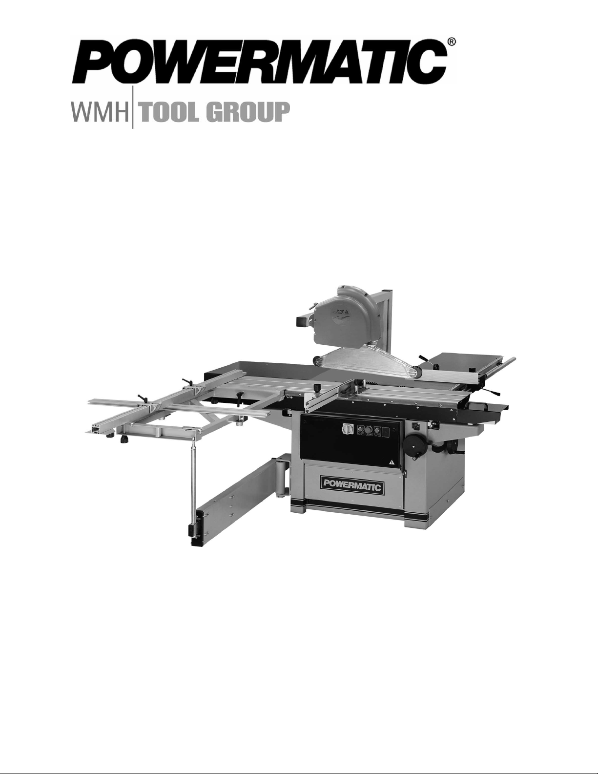
Machine Dimensions
Figure 1
7
Page 8
Unpacking
Remove crate from around machine and check
for shipping damage and ensure all parts are
intact. Report any damage immediately to your
distributor and shipping agent. Read the
instruction manual thoroughly for assembly,
alignment, maintenance and safety instructions.
Contents of crate:
1 panel saw
1 over arm
1 upper guard
2 blade guards
1 steel pin
1 crosscut table
1 mitre fence
1 arbor wrench
1 set hex wrenches
1 open-end wrench
2 extension tables
1 extension table leg
1 hardware bag
1 instruction manual
1 warranty card
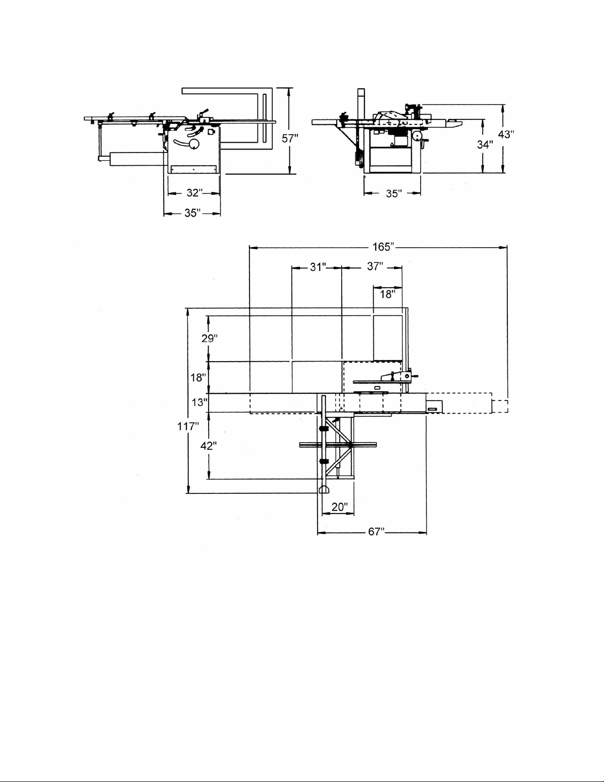
Figure 2
Installation and Assembly
(NOTE: Consult the parts breakdowns at the
back of this manual if further clarification of
assembly process is needed.)
1. Lift the machine off the pallet with crane or
forklift, using a hoist. When the machine is
sitting on the ground, it can be lifted by
removing the side cover plate (Figure 2) and
sliding forks through the two openings.
2. When the machine has been placed in the
intended location, it must be leveled to
ensure the smooth motion of the sliding
table. Use a level on top the table, and
adjust any of the four bolts in the corners of
the base (Figure 3) as necessary.
3. The support arm and sliding table have both
been locked for transportation. Release the
support arm by lifting the lower lever (Figure
4). Release the sliding table by pushing in
the upper lever (Figure 4).
Figure 3
Figure 4
8
Page 9
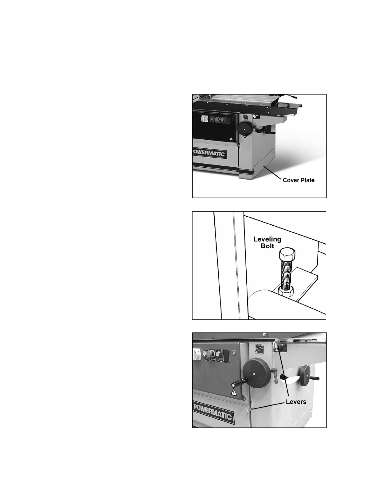
Installing Extension Tables
1. Mount the right extension tables to the edge
of the cast iron table (Figure 5) with two M8
x 25 cap screws and two M8 flat washers.
Do not tighten yet.
2. Level the extension table surface to that of
the cast iron table, then firmly tighten
screws.
3. Mount the left table extension (Figure 6)
with two M8 x 20 cap screws and two M8
flat washers to the cast iron table. Then
mount the top of the two braces (Figure 6)
to the table with two M6 flat screws, flat
washers and nuts. Mount the bottom of the
braces to the stand with two M8 x 20 cap
screws and two M8 lock washers. Do not
tighten yet.
4. Level the extension table surface to the cast
iron table, then firmly tighten all screws.
5. A leg assembly (Figure 6) is provided for the
outer edge of the extension table as shown.
The bottom end of the leg is adjustable for
leveling.
Figure 5
Figure 6
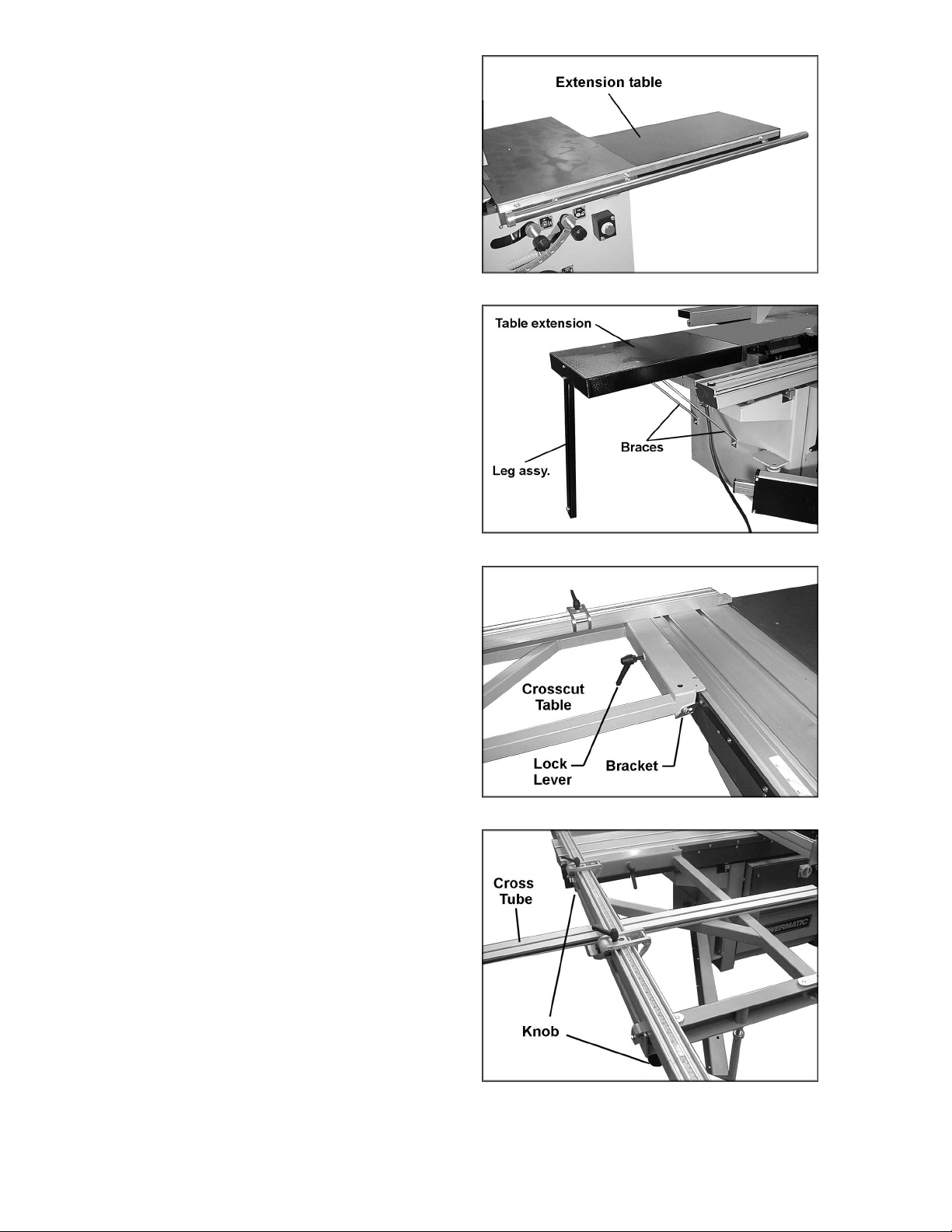
Installing Crosscut Table
1. Slide the crosscut table (Figure 7) onto the
sliding table from the left end. The rod
protruding up from the support arm should
slip into the hole on the bottom of the
crosscut table.
2. Position the two brackets (Figure 7) so that
the crosscut table will easily ride along the
flat bar on the front edge of the sliding table.
3. Tighten the lock lever to secure the table's
position.
Installing Crosscut Fence
1. The crosscut table has four holes allowing
the fence to be placed in two positions: at
the left or right of the crosscut table. Figure
8 shows the fence in the left set of holes.
2. Place the crosscut fence on to the crosscut
table and lock it in position with the knobs.
3. The cross tube is mounted to the crosscut
table as shown, and secured by two knobs
beneath.
Figure 7
Figure 8
9
Page 10
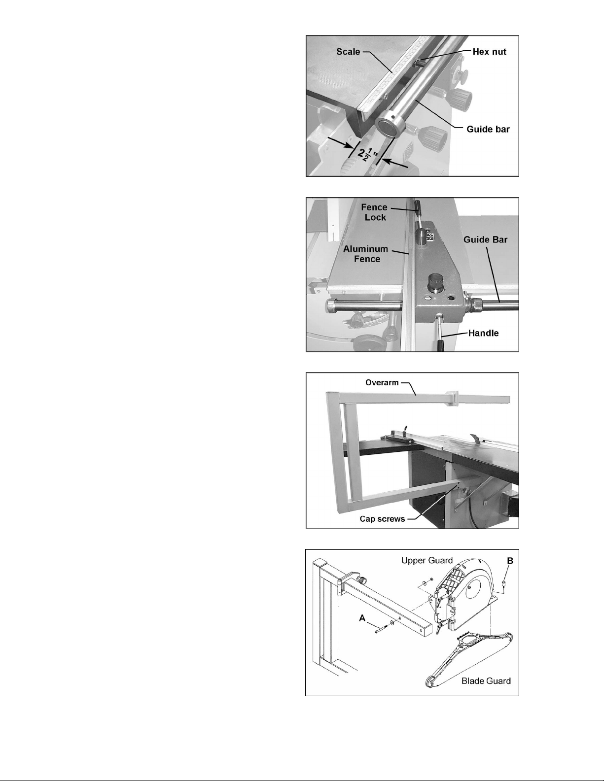
Installing Guide Bar
1. Mount the scale (Figure 9) to the edge of
the cast iron table with three M8 x 30 socket
head screws, M8 flat washers, and spacers.
2. Mount the cylindrical steel guide bar to the
edge of the cast iron table, using the four
M12 hex nuts and flat washers.
3. The outside edge of the bar along its entire
length should be approximately 2-1/2" from
the table, to allow for smooth movement of
the fence.
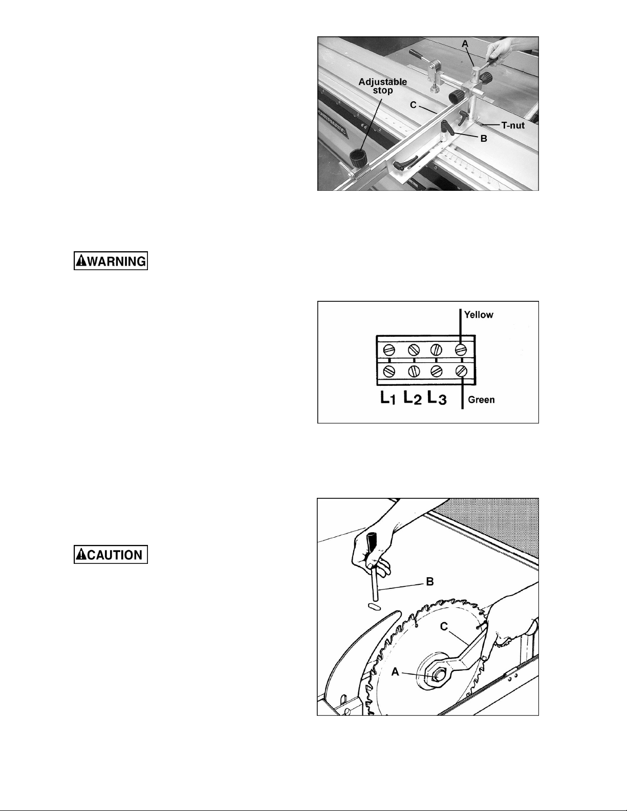
Installing Rip Fence
The rip fence assembly (Figure 10) has a cast
iron body with a sliding aluminum fence. Mount
the body by sliding it onto the end of the guide
bar while lifting the handle. Loosen the fence
lock and slide the aluminum fence onto the body
as shown.
Figure 9
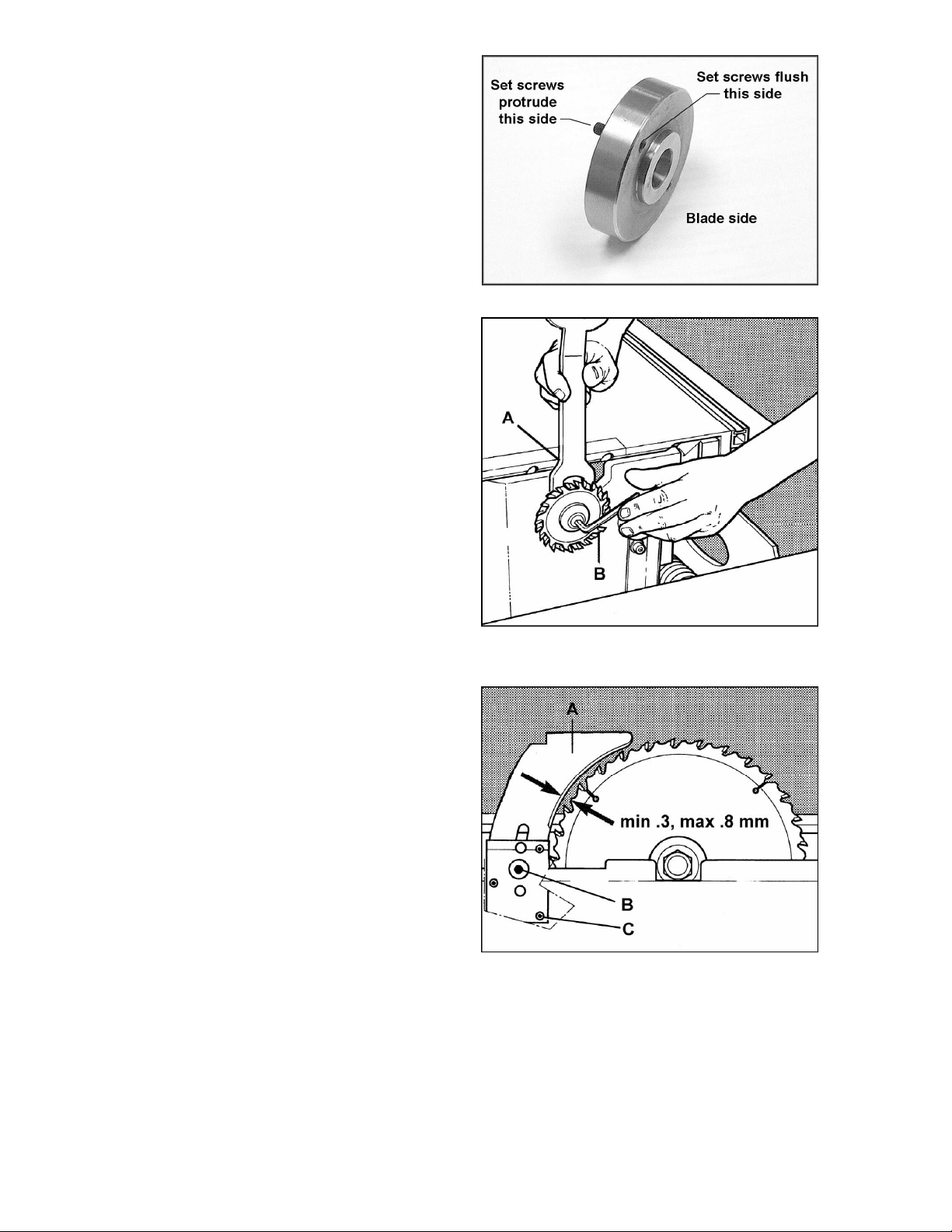
Installing Over Arm
Mount the over arm (Figure 11) with the four
M10 x 30 socket head cap screws, four M10 flat
washers and four M10 hex nuts to the holes on
the side of the frame. Tighten the screws and
nuts securely to the side of the frame.
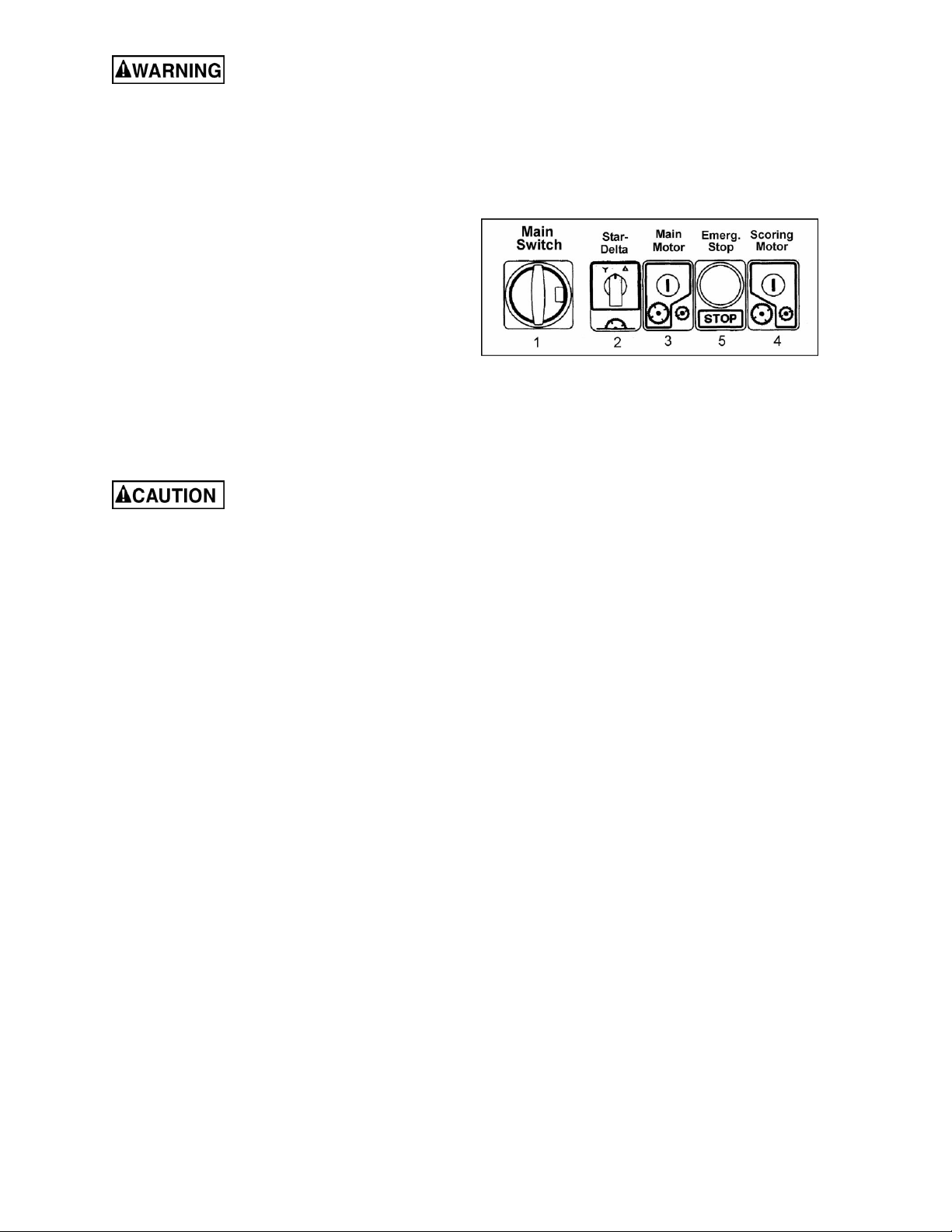
Installing Blade Guard
Mount the upper guard assembly (Figure 12) to
the over arm with two M10x80 socket head cap
screws, two M10 flat washers, and an M10 hex
nut (A, Figure 12).
Install the blade guard using the bolt (B, Figure
12).
Figure 10
Figure 11
Figure 12
10
Page 11
Installing Miter Fence
Mount the miter fence assembly as shown in
Figure 13. Tighten the rod (A, Figure 13) with
the provided pin into the stationary T-nut.
NOTE: Do not move the stationary T-nut; it has
been calibrated with the angle scale.
Screw the large lock lever (B, Figure 13) down
into the other T-nut.
Loosen the small lock levers and slide the
aluminum fence (C, Figure 13) on to the
assembly as shown. The adjustable stop can be
mounted to the fence if desired for making
multiple cuts of the same length.
Figure 13
Electrical Connections
Electrical connections must
be performed by a qualified electrican. The
machine must be properly grounded to help
prevent electrical shock and possible death.
Check that the voltage of the machine
corresponds with the voltage of your power
supply.
Remove the electrical box cover and introduce
the cable. Connect the three wires to the
terminals L1, L2, L3 (Figure 14).
The green ground wire must be connected to
the yellow wire terminal.
Turn on the main saw motor [see "Starting the
Machine"] and check that the blade arbor
rotates clockwise (as viewed from front of
machine). If it does not, turn motor off,
disconnect from power source, and exchange
wires L1 and L2.
Figure 14
Installing/Replacing Main Blade
Use care when working
around sharp blades. Use only carbide
tipped saw blades, not High Speed Steel
blades.
1. Disconnect machine from power source.
2. Push sliding table all the way to the left, and
open blade cover.
3. Raise main saw blade to its highest position
and place spanner (C, Figure 15) over the
arbor nut (A, Figure 15).
4. Insert the locking pin (B, Figure 15) into the
hole on the saw table and turn the arbor
with the spanner until the locking pin
engages the hole in the saw arbor pulley.
Figure 15
11
Page 12
5. Unlock the nut (NOTE: Left hand threads –
loosen by turning clockwise).
6. Make sure the set screws in the adaptor are
set flush on the blade side. (They should
protrude to the rear to engage the arbor for
positive drive). See Figure 16. Clean the
mating surfaces, install new blade, and
tighten arbor nut securely.
7. Remove locking pin (B, Figure 15) and close
blade cover.
SAFETY TIP: Tape a red rag on the locking pin
and drape it over the blade while pin is inserted.
This will remind you to remove the pin before
starting the saw!
Installing/Replacing Scoring Blade
1. Disconnect machine from power source.
2. Push sliding table all the way to the left and
open blade cover.
3. Tilt scoring blade all the way, and place
spanner (A, Figure 17) on the flat of the
arbor.
4. Loosen the bolt with the hex wrench (B,
Figure 17). (NOTE: Right hand threads-turn
counterclockwise to loosen).
5. Mount scoring blade and re-tighten bolt.
Close blade cover.
Riving Knife
The machine is equipped with a riving knife (A,
Figure 18) for use with saw blades up to 315mm
in diameter.
Figure 16
Figure 17
The purpose of the riving knife (or "splitter") is to
prevent the kerf from closing as it leaves the
cutting teeth, and thereby reduce the chance of
the kerf coming in contact with the up-running
teeth of the blade and causing binding or a
dangerous kickback. When the forward edge of
the workpiece reaches the riving knife, the knife
also helps guide the rest of the cut and will
prevent the up-running teeth from scoring the
workpiece.
The riving knife must be adjusted so that over its
entire length the gap between saw blade and
riving knife does not exceed 3 to 8mm.
The riving knife can be adjusted in both vertical
and horizontal directions. The highest point of
the riving knife should never exceed 3mm above
the highest placed saw blade tooth.
Use the central bolt (B, Figure 18) and the three
adjustment screws (C, Figure 18). After
adjustment, always lock the central bolt (B,
Figure 18).
Figure 18
12
Page 13
Do not remove the riving
knife for saw operations.
For slotting or grooving, the riving knife has to
be adjusted in such a way that the upper part of
the riving knife is never set lower than the
highest sawtooth in use.
Starting the Machine
NOTE: The machine will not start if the blade
cover or the rear door is open.
When starting in Star-Delta mode, proceed as
follows (Figure 19):
1 – Turn Main Switch to position "I".
2 – Turn Star-Delta switch into star position "Y".
3 – Push Main Motor start button.
2 – After five seconds, put Star-Delta switch into
delta position "∆".
This five second delay is
necessary for the motor to gain full speed
before switching to delta. If you forget to
switch to delta, the motor will operate at full
speed but without power, and the motor may
become damaged.
4 – Push Scoring Motor start button (main motor
must be running).
5 – Emergency stop button halts both main and
scoring motors.
The main motor is equipped with an automatic
brake which stops the motor within 10 seconds
after the machine is shut off.
Fuses are located inside the electrical control
panel. The machine must be disconnected from
power supply when opening this panel.
This machine has overload protection on both
main and scoring motors. Should the motor be
shut off by one of these protectors, wait a few
minutes until the overload has cooled down
before restarting.
Figure 19
Dust Collection
It is strongly recommended that a dust collection
system be connected to the HPS67. The dust
collector should have sufficient capacity for this
size machine. Both the outlet on the blade guard
and on the machine base should be connected
to the dust collection system.
13
Page 14
Adjustments
Sliding Table Parallel to Blade
The position of the sliding table relative to the
machine is factory set, but should be checked
periodically as the saw receives use. To ensure
a clean cut, the sliding table must be set parallel
to the saw blade. If adjustment is ever needed,
proceed as follows:
1. The bolts (B, Figure 20) are used to adjust
the height of the sliding table. They are preset at the factory.
2. Use bolts (A, Figure 20) to correct
parallelism between sliding table and saw
blade.
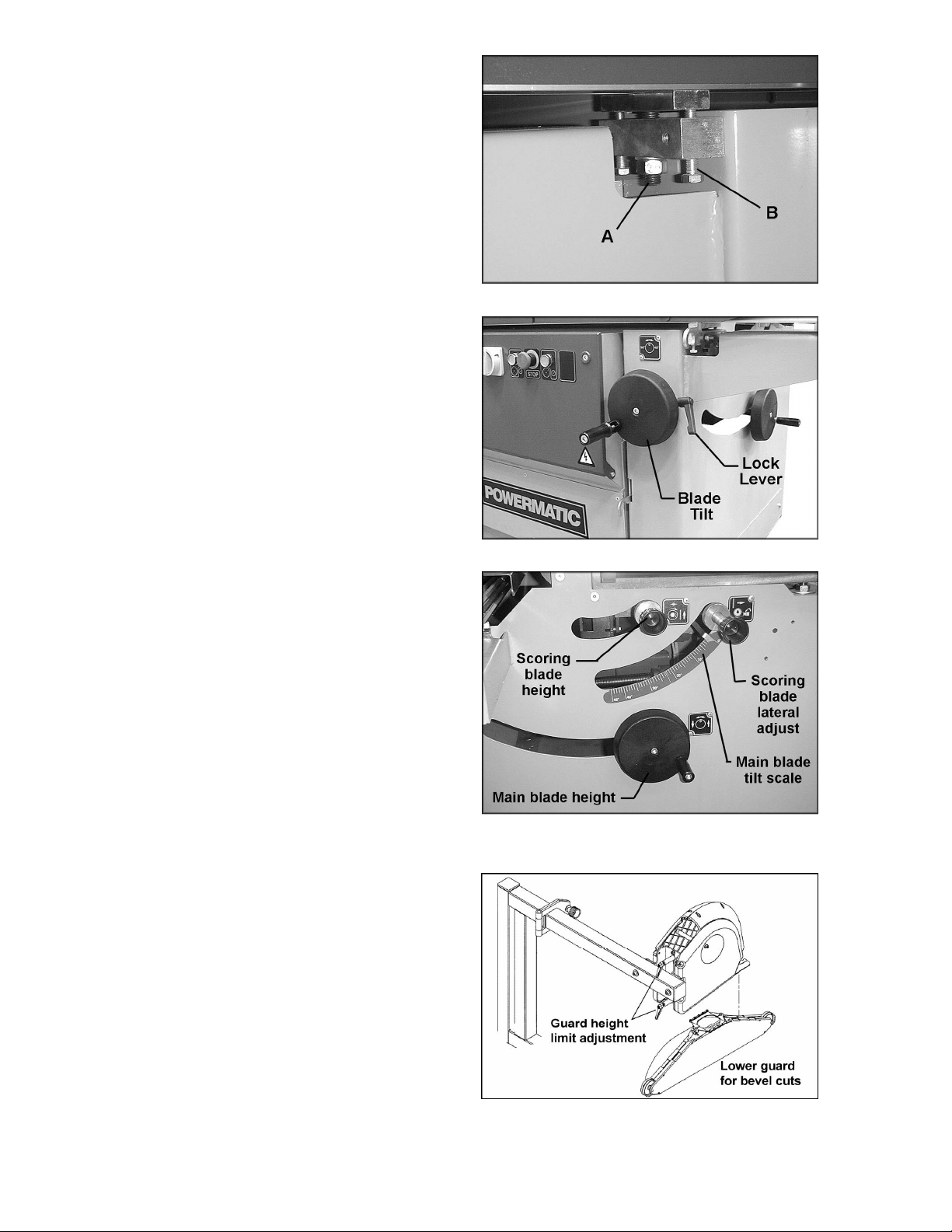
Setting Main Blade (Figures 21 and 22)
Adjust the height of the saw blade with the
handwheel on the side of the machine. One turn
of the handwheel raises or lowers the blade by
2.5mm.
The blade is tilted by using the front handwheel.
The blade can be tilted at any angle between 90
and 45 degrees. After setting, lock the blade in
this position with the lock lever. The blade angle
can be read on the tilt scale.
NOTE: The 90 and 45 degree stops are pre-set
at the factory and should require no adjustment.
After setting the main blade at the desired
cutting angle, the cutting depth of the scoring
blade must be re-set.
Setting Scoring Blade
Figure 20
Figure 21
Turn the scoring blade height knob (Figure 22).
One turn raises or lowers the scoring blade by 3
mm.
Each time the main saw blade is resharpened or
replaced, the scoring blade must be adjusted
laterally to match the main blade teeth. This
must be done to ensure a clean cut free of
splintering. Lateral movement is obtained by
turning the lateral adjustment knob (Figure 22),
then locking it at the desired setting.
Setting Blade Guard
The two handles (Figure 23) are for setting the
guard height limits. Loosen a handle and slide
the bracket as needed. Both handles on the
guard should be tightened securely before
operating the panel saw.
When the arbor is tilted for a bevel cut, mount
the alternate lower guard with the convex back
(Figure 23).
Figure 22
Figure 23
14
Page 15
When bevel cutting, make
sure the appropriate blade guard has been
mounted before operating the saw.
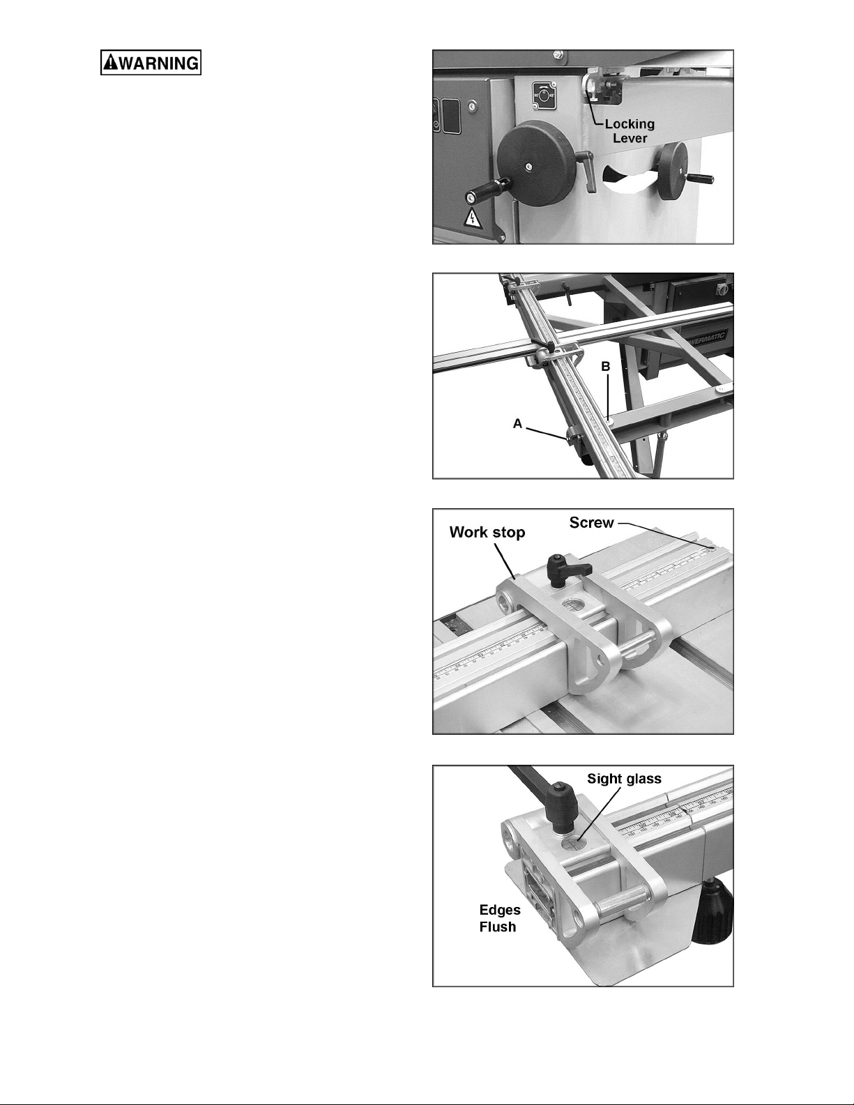
Sliding Table Lock
When loading panels and when cutting using the
rip fence, the sliding table should be locked.
To lock the sliding table, pull lever (Figure 24)
into one of the slots in the sliding table.
Over a long period of time, if many short
movements of the sliding table are made (e.g.
crosscutting solid wood) then it is possible that
the ball carrier between the upper and lower part
of the sliding table will move. This means it will
no longer be correctly positioned to allow the
sliding table to slide through its full course. The
operator will feel resistance in the sliding table
motion and the full stroke will not be achieved.
This effect can be corrected simply by pushing
the table with a few short, light pushes against
the buffer stop at the end, until the position of
the ball carrier is adjusted and the table can be
moved again along its full stroke.
Figure 24
Crosscut Fence
The 90-degree angle of the fence is factory set.
However, should adjustment ever be needed,
proceed as follows:
1. Loosen the two bolts (A, Figure 25).
2. Turn bolt (B, Figure 25) to open or close the
angle of the fence in relation to the saw
blade.
3. Re-tighten bolts (A, Figure 25).
Before using the first time, and each time a new
blade is installed, the scales must be calibrated.
Proceed as follows:
1. Put the stop (Figure 26) at a certain
measure and cut off a sample.
2. Measure the exact length of the sample.
Loosen the screw (Figure 26) which holds
the scale and move the scale until the
measurement corresponds to the length of
the previously cut sample. The main part of
the fence is now calibrated to the saw blade.
3. The scale on the telescopic extension of the
fence should now be checked and adjusted.
Move the other stop to the outermost edge
of the extension fence until the edge of the
stop is flush with the edge of the fence
(Figure 27). Lock the stop in position by
tightening the handle.
NOTE: DO NOT loosen the stop until the
adjustment procedure has been completed.
Figure 25
Figure 26
Figure 27
15
Page 16

4. Record the measurement in the sight glass.
5. Add 2” to this measurement and slide out
the extension until the new measurement is
read at the end of the fixed fence (Figure
28). NOTE: Be careful to set this correctly,
because the scale on the sliding fence
reads opposite the scale on the fixed fence.
6. Lock the extension fence to this new
measurement by tightening the knob
underneath.
7. With a 3mm hex wrench, loosen the set
screws underneath the short movable fence
extrusion (Figure 29), and slide the
extrusion to 2” of the fixed fence (Figure 30).
Tighten the set screws.
8. When using the telescopic extension, make
sure the stop is positioned flush with the end
of the movable extrusion.
9. The best way to check if all scales
correspond is to make several test cuts on
the different scales.
Figure 28
Wood Cap
After a period of use, if the wood protection cap
at the end of the crosscut fence is cut away, a
new one must be made. See Figure 31 for the
correct dimensions.
Figure 29
Figure 30
Figure 31
16
Page 17

Miter Fence
The flat T-nut which holds the vertical rod of the
clamp is factory set and must remain in its
position to make the angle scale correspond.
1. To set the required angle, loosen the rod (A,
Figure 32) with the provided pin as shown.
Loosen the large lever (B, Figure 32).
2. To slide the fence (C, Figure 32) toward or
away from the saw blade, unlock the two
smaller levers.
3. Reading the angle is done at the edge of the
aluminum bracket. An adjustable stop can
be mounted to the miter fence as shown in
Figure 32, for making multiple cuts of the
same length.
Rip Fence
1. To move the rip fence, shown in Figure 33,
turn the micro-adjust gear counterclockwise,
and lift the handle. The fence should slide
freely on the guide bar.
2. To lock the fence in position, push the
handle down and tighten the micro-adjust
gear by turning it clockwise.
3. Micro-adjustment is achieved by locking the
micro-adjust gear, by holding the handle in
the upright position, and by turning the
micro-adjust knob.
Figure 32
Figure 33
4. After adjustment, push handle down to lock
the fence in place.
NOTE: When cutting small workpieces with the
saw blade tilted at 45 degrees, the aluminum rip
fence should be used in the low position:
1. Loosen the aluminum fence lock, slide the
fence off and slide it back on in the low
position, as shown in Figure 34.
2. Tighten the aluminum fence lock.
When cutting solid wood using the rip fence, to
avoid the wood getting stuck between the fence
and riving knife (which can result in a dangerous
kickback) reposition the aluminum fence so that
its end protrudes just past the end of the riving
knife.
Rip Fence Scale Calibration
Each time a new blade is mounted, the rip fence
scale has to be calibrated to the new blade.
Figure 34
With the fence at a convenient spot, cut a
sample and measure its exact width.
17
Page 18

Loosen the three screws on the scale (Figure
35) and nudge the scale until it matches the cut
measurement. Make another cut to confirm the
measurement.
To avoid the fence contacting the rotating saw
blade, the stop ring must be adjusted.
Slide the fence to about 10mm from the saw
blade.
Slide the stop ring across the round guide bar
until it comes up against the casting of the
fence. Tighten the set screw on the stop ring.
Tensioning the Belt
To tension the belt on the main motor:
1. Remove the access door and loosen the
four bolts (Figure 36) which hold the motor.
2. Tension the belt by pushing the motor to the
right, and tighten the four bolts.
Make sure the belt is not
over-tensioned as this may lead to damage
to the saw arbor and belt.
Figure 35
To tension the belt on the scoring motor:
1. Loosen the two nuts (Figure 37) which hold
the scoring motor.
2. While pushing the motor down, tighten the
two nuts.
When replacing belts on the main or scoring
motor, make sure the belt is well positioned into
the v-groove of the pulley.
Precision Tuning Your Panel Saw
Your HPS67 is a precision machine designed to
give accurate performance over many years.
But like all fine equipment, it can only meet the
tight tolerances required if it is tuned correctly.
Your machine has been so designed that all the
major parameters which influence the quality of
cut can be adjusted by non-technical staff.
These tuning procedures should be carried out
in the proper order, as later adjustments depend
upon the earlier being correct.
The four steps of the procedure are:
1. Free Cut from blade to sliding table
2. Free Cut from blade to rip fence
3. Square Cut
4. Scoring Saw
Figure 36
Figure 37
18
Page 19

Free Cut (Blade to Sliding Table)
The sliding table does not run exactly parallel to
the saw blade. It runs away from the back teeth
by a fraction of a millimeter. This is called "free
cut."
A very slight amount of free cut is desirable to
avoid the problems of back cutting due to saw
blade flutter. All saw blades vibrate to some
extent. They flutter less at the front, where the
cutting teeth are held stable by the material,
than at the back.
If the table were set absolutely parallel to the
saw blade, the back teeth could contact the
material and spoil the clean cut achieved by the
front teeth. As the back teeth are ascending,
they could cause chip out on the top surface of
laminated boards.
The free cut required is less than .05 mm over
one meter of travel.
A dial indicator is not required. You can use your
ears to compare the noise of the front teeth with
that of the back teeth. To do this will require a
workpiece shorter than the distance between
front and back teeth. The saw blade should be
raised to its maximum height to achieve the
most contrast.
1. Lay the workpiece against the crosscut
fence and make a cut.
2. Hold the workpiece firmly after the front
teeth have cut and push it on past the back
teeth. As you pass the back teeth you
should feel rather than hear a slight tingling
or whisper. If there is no sound from the
back teeth, you probably have too much
("positive") free cut. If the noise from the
back teeth is similar to that of the front teeth,
there is too little ("negative") free cut and the
table is running in towards the back of the
blade.
3. Having passed the back teeth, stop level
with the riving knife and cut backwards. The
back teeth will make a noise as they are
now cutting the material.
The workpiece must be held
down firmly when making this backward cut.
4. As you continue past the front teeth, the
noise from the front teeth should be equal to
or slightly less than the noise from the back
teeth. Slight back cutting on the backstroke
equals slight free cut on the forward stroke.
5. If the front teeth make more noise than the
back, the free cut is positive; if they make no
noise, the free cut is negative. If the noise
relationship front teeth to back teeth on the
forward stroke is the same as the noise
relationship back teeth to front teeth on the
back stroke (on a scale of 100, 100/30 in
each case), the sliding table is running
exactly parallel to the blade (zero free cut).
To correct the free cut, one end of the sliding
table must be moved outward or inward. It
doesn't matter whether you move the left or the
right end. The only consideration is that there is
enough clearance between the sliding table and
the fixed cast iron table at the end you are
moving.
1. At the end you have decided to move,
loosen the hex nut (A, Figure 38) holding the
sliding table to the frame.
Figure 38
2. Loosen the other two hex nuts in the middle
of the sliding table so that the table will pivot
at the remaining fixed end.
3. Move the table end in or out as needed then
retighten the table mounting nuts.
4. Check again to confirm the free cut is
satisfactory. Repeat the process if needed.
NOTE: The sliding table should be
approximately 0.3 mm higher than the fixed cast
iron table (thickness of a piece of paper). This is
pre-set at the factory, but if adjustment should
ever be needed, use the four height adjustment
bolts (Figure 38) on each end of the table.
Trouble-shooting Free Cut
(Blade to Sliding Table):
Symptoms of positive free cut:
Back cutting on rip fence side. Workpiece on
cast iron table pulled into back of sawblade.
Chip out on top.
Machine cutting out of square. Workpiece
moves slightly on sliding table due to pressure of
saw blade, without operator noticing.
19
Page 20

Scoring saw correctly aligned for sliding table is
out of alignment on rip fence side and viceversa.
Chip out on the bottom as alignment of scoring
saw with main blade inconsistent due to
movement of workpiece.
Symptoms of negative free cut:
Back cutting on sliding table side. Workpiece
runs into back of saw blade. Chip out on top.
Machine cutting out of square. Workpiece
moves slightly on sliding table due to pressure of
saw blade, without operator noticing.
Chip out on the bottom as alignment of scoring
saw with main blade inconsistent due to
movement of workpiece.
NOTE: The above test depends upon the riving
knife being properly in line with the blade.
Free Cut (Blade to Rip Fence)
If the free cut on the rip fence side is negative,
the symptoms are fairly obvious. The workpiece
gets stuck between the back teeth and the fence
and, in the worst case gets kicked back.
into the saw blade for half the direction
which the back teeth just cut. The width here
will correspond to the distance between the
front teeth and the fence.
Between the teeth marks from the back teeth
and front teeth there will be a small ridge. The
height of this ridge is the free cut over the length
of the saw blade. This ridge should hardly be
visible, but just possible to feel.
To correct the free cut:
Loosen the nuts on the outside (third) bolt
holding the guide bar on which the rip fence
slides. See Figure 39.
If the free cut is positive, other problems arise
which are not so easily recognized, as for
example, an incorrect rip fence setting. The
following procedure will help you compare the
distance between front teeth and rip fence with
the distance between back teeth and rip fence:
1. Lower scoring blade all the way down, and
out of the way.
2. Raise main blade to its highest position.
3. Take a workpiece of convenient size (e.g.
12" x 18") and edge one long side using the
sliding table.
4. Set the rip fence slightly narrower than the
workpiece, and cut the opposite long side of
the workpiece using the fence.
5. Stop the workpiece when the trailing edge is
level with the riving knife (i.e. has passed
the back teeth.)
6. Using the rip fence micro adjustment, move
the rip fence 1/4 turn inward, and pull
workpiece backward almost to sawblade
middle. The back teeth will then cut, and
where they have cut, the workpiece width
will correspond to the distance between the
back teeth and the rip fence.
7. Remove workpiece in normal cutting
direction.
8. Flip the workpiece over so that the trailing
edge becomes the leading edge and feed
Figure 39
Move the bar, and therefore the fence, in or out
by pivoting it upon the second bolt.
When corrected, tighten outside (third) bolt.
Trouble-shooting Free Cut
(Blade to Rip Fence)
Symptoms of negative free cut:
Workpiece gets jammed between fence and
back of saw blade, danger of kickback.
Backcutting, top chip out to the right of blade.
Symptoms of positive free cut:
Backcutting to the left of saw blade. Workpiece
on left is pulled into back teeth. Chip out on top.
Scoring saw, while correctly aligned on sliding
table side, is out of alignment for ripping.
When the rip fence section is in a pulled back
position, the actual width cut is less than that
shown on the scale.
NOTE: The above check depends on the riving
knife being in line with the blade, not bent,
narrower than the tooth kerf and wider than the
body of the blade.
20
Page 21

Square Cut
1. Take a panel approximately 40" and cut five
times round, always turning the cut edge up
against the crosscut fence (counterclockwise with crosscut fence in normal
position). The fifth cut cuts the same edge
as the first.
2. The last offcut strip (whose left side was the
last cut and whose right side was the first
cut) must be the same width at both ends if
every corner was precisely 90 degrees. Any
error in the squareness has been multiplied
four times.
3. Break the strip and lay the ends side by side
and check the difference. (Break the strip in
such a way that you know afterward which
was front and which was back; e.g. front bit
short, back bit long).
Unlike other methods of checking for
squareness, this system tells you which way to
move the fence should adjustment be
necessary. It depends upon the shape of the
fifth offcut strip:
If front thick, back thin – move fence counterclockwise.
If front thin, back thick – move fence clockwise.
1. The crosscut fence position is adjusted at
the outer attachment point only. Loosen the
clamping device on the bottom of the
crosscut fence.
2. Loosen the adjust the cross cut fence
bracket on the top surface of the table.
3. Re-tighten the cross cut fence clamp device.
4. Perform another test to check the setting.
NOTE: An incorrect free cut on the sliding table
can affect the squaring; see "Free Cut (Blade to
Rip Fence)"
Thus, the scorer and the main blade are slightly
out of alignment with regard to the tilt axis.
As the blades are tilted to 45 degrees, this
misalignment in the horizontal plane also
becomes a misalignment in the vertical plane.
The scorer must, therefore, be "raised" (moved
to the left) or "lowered" (moved to the right)
depending on whether the free cut on the sliding
table, or the rip fence, needs to be compensated
for.
The free cut can influence the scoring cut; it is
essential to carry out the first two free-cut tests
mentioned above before adjusting the scoring
blade.
Operation
The panel saw is designed for the following work
and is equipped with safety devices for these
particular procedures. It is not designed to work
materials such as ferrous or non-ferrous metals.
Available procedures:
• Ripping with the parallel saw fence with or
without the saw blade tilted and the fence
upright or in the low position.
• Right-angled or mitre cuts with the 90
degree fence mounted to the sliding table
with tilted or vertical saw blade.
• Crosscutting workpieces using the
adjustable stop on the 90 degree fence.
• Cutting panels or solid wood on the sliding
table.
The machine has overload protection on both
main and scoring motors. Should the motor be
shut off by one of these protectors, it is
necessary to wait a few minutes until the
overload has cooled down before restarting.
Scoring Blade
The scoring blade should penetrate the material
about 2mm.
Problems with the alignment of the scoring blade
can normally be traced back to too much free
cut. For this reason, the free cut must be
checked for correctness before the scoring saw
is adjusted.
For example, when the main blade is tilted to 45
degrees, the scoring blade may need to be
readjusted sideways.
The tilt axis is independent of the free cut on the
sliding table rip fence. The scorer alignment at
90 degrees takes the free cut into account.
21
Page 22

Maintenance
NOTE: All bearings in the machine are selfsealed and require no lubrication.
The sliding table should be cleaned once a
week, and all sawdust and chips removed.
From both sides of the sliding table, blow out
the dust which has accumulated between the
two sections and on the ball carrier. This can be
done more efficiently when the upper part of the
sliding table is slid to the rear. Then repeat the
process when the upper part is slid to the front
end.
Remove any resin deposits on sliding table and
other surfaces.
After blowing out the dust, spray a thin oil onto
the steel rods (Figure 40) on both the upper and
lower part of the sliding table. Never use a thick
oil or grease!
Lubricate all moving parts with a light coating of
oil.
Blow sawdust out of the cooling fan and motor.
Figure 40
22
Page 23

Troubleshooting
Trouble Probable Cause Remedy
Access door open. Close door completely.
Machine will not start
when start button is
pushed.
Excessive vibration.
Cuts out-of-square
when crosscutting.
Motor stalls or
workpiece binds or
burns.
No power; possible shortage. Check power source.
Star-delta switch in wrong position. Switch must be on “Y” position.
Main switch off. Put main switch on “1”.
Tilt or raising lock knobs not tight. Tighten knobs.
Blade out of balance. Have it balanced or replaced.
Worn or damaged belt. Replace belt.
Bad motor. Replace motor.
Fence misaligned. Reset fence angle.
Table not aligned with blade arbor. Realign table.
Excessive feed. Reduce feed.
Dull or incorrect blade. Replace blade.
Bad motor. Replace motor.
Fence misaligned. Realign fence.
Lock knob not released. Loosen lock knob.
Tilt or saw raising
handwheels difficult
to turn.
After starting, arbor
won’t turn and motor
makes straining
noises.
Motor overheats.
Thermal overload.
Motor starts slowly or
fails to come up to full
speed.
Worm and worm gear segment caked
with sawdust and pitch.
Worm and worm gear segment out of
alignment.
Pin not removed from arbor hole after
changing blade.
Motor overloaded.
Improper cooling of motor.
Overload not set on automatic reset,
or overload is faulty.
Low voltage.
Start switch malfunction. Replace switch.
Clean and re-grease.
Realign worm and worm gear
segment.
Remove pin.
Correct overload condition such as
reducing feed rate.
Clean sawdust from fan and duct
areas of motor.
Contact service technician.
Request voltage check from power
company and correct low voltage
condition.
Bad motor. Replace motor.
23
Page 24

Trouble Probable Cause Remedy
Reduction of speed
during cutting.
Motor fails to develop
full power.
Belt tension incorrect. Properly tension belt.
Motor overload due to incorrect feed
rate.
Dull blade(s). Resharpen or replace.
Power line overloaded. Correct overload condition.
Undersize wires in supply system. Increase supply wire size.
Low voltage.
Bad motor. Replace motor.
Optional Accessories
6080152 Saw Blade, 120mm/24T, 20mm Bore
6080153 Saw Blade, 12”/72T, 30mm Bore
HPS67-159 Dado Bushing 1”
Reduce feed rate.
Request voltage check from power
company and correct condition.
Replacement Parts
Replacement parts are listed on the following pages. To order parts or reach our service department, call
1-800-274-6848 between 7:30 a.m. and 6:00 p.m. (CST), Monday through Friday. Having the Model
Number and Serial Number of your machine available when you call will allow us to serve you quickly and
accurately.
24
Page 25

Parts List: Motor and Arbor Assembly
Index No. Part No. Description Size Qty
1............... HPS67-101..............Collar .................................................................................................... 1
2............... HPS67-102..............Arbor Shaft............................................................................................ 1
3............... HPS67-103..............Shaft ..................................................................................................... 1
4............... HPS67-104..............Bushing................................................................................................. 1
5............... HPS67-105..............Retainer Ring ........................................................................................ 1
6............... HPS67-106..............Bracket.................................................................................................. 1
7............... HPS67-107..............Retainer Block....................................................................................... 1
8............... HPS67-108..............Spacer...................................................................................................1
9............... HPS67-109..............Sleeve................................................................................................... 1
10............. HPS67-110 ..............Motor Base............................................................................................ 1
11............. HPS67-111 ..............Flange Washer ...................................................................................... 1
12............. HPS67-112 ..............V-Belt .................................................................................................... 2
13............. HPS67-113 ..............Arbor Pulley........................................................................................... 1
14............. HPS67-114 ..............Shaft ..................................................................................................... 1
15............. HPS67-115 ..............Hose Clamp .......................................................................................... 3
16............. HPS67-116 ..............Riving Knife Holder Plate....................................................................... 1
17............. HPS67-117 ..............Spacer...................................................................................................1
18............. HPS67-118 ..............Strap Bracket.........................................................................................1
19............. HPS67-119 ..............Flange Nut Height Adjustment ............................................................... 2
20............. HPS67-120 ..............Spacer...................................................................................................2
21............. HPS67-121 ..............spacer ................................................................................................... 1
22............. HPS67-122 ..............Nut Inclination........................................................................................ 2
23............. HPS67-123 ..............Motor Pulley.......................................................................................... 1
24............. HPS67-124 ..............Bracket.................................................................................................. 1
25............. HPS67-125 ..............Bracket.................................................................................................. 1
26............. HPS67-126 ..............Riving Knife .......................................................250/300 ...................... 1
27............. HPS67-127 ..............Bracket.................................................................................................. 1
31............. ----------------..............Saw Blade (not included) ....................................................................... 1
32............. HPS67-132 ..............Spring....................................................................................................1
33............. HPS67-133 ..............Handwheel ............................................................................................ 1
34............. HPS67-134 ..............Pin......................................................................Φ 4 x 24mm................ 1
35............. HPS67-135 ..............Handwheel Mouting Handle ................................................................... 1
36............. HPS67-136 ..............Handwheel ............................................................................................ 2
37............. HPS67-137 ..............Collar ....................................................................................................1
38............. HPS67-138 ..............Stud ...................................................................M8 x 60 ...................... 1
39............. HPS67-139 ..............Bushing................................................................................................. 2
40............. HPS67-140 ..............Spindle.................................................................................................. 1
41............. HPS67-141 ..............Plate...................................................................................................... 1
42............. HPS67-142 ..............Mount Bracket ....................................................................................... 1
43............. HPS67-143 ..............Spindle Bracket ..................................................................................... 1
44............. HPS67-144 ..............Spindle.................................................................................................. 1
45............. HPS67-145 ..............Cover Tube ........................................................................................... 1
46............. HPS67-146 ..............Plate...................................................................................................... 2
47............. HPS67-147 ..............Plate...................................................................................................... 1
48............. HPS67-148 ..............Handle................................................................................................... 1
49............. HPS67-149 ..............Strap Bracket.........................................................................................1
50............. HPS67-150 ..............Tube...................................................................................................... 1
51............. HPS67-151 ..............Sleeve................................................................................................... 1
52............. BB-6003ZZ ..............Ball Bearing........................................................................................... 2
53............. HPS67-153 ..............Stud ...................................................................M12 x 50 .................... 2
54............. HPS67-154 ..............Motor..................................................................5HP, 3Ph, 230V.......... 1
................. HPS67-154A............Motor..................................................................3HP, 1PH, 230V ......... 1
55............. HPS67-155 ..............Bolt Handwheel ..................................................................................... 1
56............. HPS67-156 ..............Bracket.................................................................................................. 1
57............. TS-1504051.............Socket Head Cap Screw.....................................M8 x 25 ...................... 1
58............. TS-1504041.............Socket Head Cap Screw.....................................M8 x 20 ...................... 5
60............. TS-1541031.............Nylon Lock Hex Nut............................................M8.............................. 2
25
Page 26

61............. TS-1490031.............Hex Head Cap Screw .........................................M8 x 20 ...................... 1
62............. TS-1540061.............Full Hex Nut .......................................................M8.............................. 6
63............. TS-2238751.............Socket Head Cap Screw.....................................M8 x 75 ...................... 1
64............. TS-1504131.............Socket Head Cap Screw.....................................M8 x 70 ...................... 2
65............. TS-2239101.............Socket Head Cap Screw.....................................M10 x 8 ...................... 1
66............. TS-1505011.............Socket Head Cap Screw.....................................M10 x 16 .................... 2
67............. HPS67-157 ..............Flange Washer ...................................................................................... 1
68............. TS-2360101.............Flat Washer........................................................M12............................ 2
69............. TS-2342121.............Full Nylon Inset Lock Nut....................................M12............................ 2
70............. TS-1490041.............Hex Cap Screw ..................................................M8 x 25 ...................... 4
71............. TS-2312241.............Hex Jam Nut ......................................................M24............................ 4
72............. TS-1504011.............Socket Head Cap Screw.....................................M8 x 10 ...................... 1
73............. TS-1516031.............Flat Head Socket Cap Screw..............................M10 x 30 .................... 1
74............. TS-1506051.............Socket Head Cap Screw.....................................M12 x 40 .................... 1
75............. TS-1524011.............Socket Set Screw...............................................M8 x 8........................ 4
76............. TS-1490061.............Hex Head Cap Screw .........................................M8 x 35 ...................... 1
77............. TS-2361081.............Lock Washer ......................................................M8.............................. 1
78............. TS-1524041.............Socket Set Screw...............................................M8 x 16...................... 2
79............. TS-1490081.............Hex Head Cap Screw .........................................M8 x 45 ...................... 3
80............. TS-1514051.............Flat Head Socket Cap Screw..............................M6 x 30 ...................... 1
81............. TS-1541021.............Nylon Lock Hex Nut............................................M6.............................. 1
82............. TS-1550041.............Flat Washer........................................................M6.............................. 1
83............. HPS67-158 ..............Dado Bushing.....................................................30mm......................... 1
84............. TS-1522061.............Socket Set Screw...............................................M5 x 20...................... 2
26
Page 27

Motor and Arbor Assembly
27
Page 28

Parts List: Scoring Motor and Arbor Assembly
Index No. Part No. Description Size Qty
1............... HPS67-201..............Collar .................................................................................................... 1
2............... ---------------...............Scoring Blade (not included) .................................................................. 1
3............... HPS67-203..............Arbor Shaft............................................................................................ 1
4............... HPS67-204..............Bushing................................................................................................. 1
5............... HPS67-205..............Sleeve................................................................................................... 1
6............... HPS67-206..............V-Belt .................................................................................................... 1
7............... HPS67-207..............Arbor Pulley........................................................................................... 1
8............... HPS67-208..............Tilt Bracket ............................................................................................ 2
11............. HPS67-211 ..............Micro Switch.......................................................................................... 1
14............. HPS67-214 ..............Handle Knob ......................................................................................... 1
15............. HPS67-215 ..............Bushing................................................................................................. 1
17............. HPS67-217 ..............Bracket.................................................................................................. 1
18............. HPS67-218 ..............Adjustment Screw.................................................................................. 1
19............. HPS67-219 ..............Block ..................................................................................................... 1
20............. HPS67-220 ..............Arbor Housing ....................................................................................... 1
21............. HPS67-221 ..............Shaft ..................................................................................................... 1
22............. HPS67-222 ..............Shaft Guide ........................................................................................... 1
23............. HPS67-223 ..............Shaft Bracket......................................................................................... 1
24............. HPS67-224 ..............Guide Bracket........................................................................................1
25............. HPS67-225 ..............Spring....................................................................................................1
26............. HPS67-226 ..............Motor Pulley.......................................................................................... 1
27............. HPS67-227 ..............Strap Bracket.........................................................................................1
28............. HPS67-228 ..............Bushing................................................................................................. 1
32............. HPS67-232 ..............Saw Unit Assembly................................................................................ 1
33............. HPS67-233 ..............Scoring Motor.....................................................3/4HP, 230V............... 1
35............. BB-6003ZZ ..............Ball Bearing........................................................6003ZZ....................... 2
36............. BB-608ZZ ................Ball Bearing........................................................608ZZ......................... 2
37............. TS-1504041.............Socket Head Cap Screw.....................................M8 x 20 ...................... 1
38............. TS-1515021.............Flat Head Socket Cap Screw..............................M8 x 20 ...................... 1
39............. TS-1515031.............Flat Head Socket Cap Screw..............................M8 x 25 ...................... 1
40............. TS-1515011.............Flat Head Socket Cap Screw..............................M8 x 16 ...................... 1
41............. TS-2248162.............Socket Head Button Screw.................................M8 x 16 ...................... 2
42............. TS-1550041.............Flat Washer........................................................M6.............................. 2
43............. TS-1550061.............Flat Washer........................................................M8.............................. 7
45............. TS-2311081.............Hex Nut..............................................................M8.............................. 3
48............. TS-1501081.............Socket Head Cap Screw.....................................M4 x 30 ...................... 1
51............. TS-1490031.............Hex Head Cap Screw .........................................M8 x 20 ...................... 2
52............. TS-1490021.............Hex Head Cap Screw .........................................M8 x 16 ...................... 2
53............. TS-2310162.............Hex Nut..............................................................M16............................ 1
54............. TS-1522041.............Socket Set Screw...............................................M5 x 12...................... 1
55............. TS-1504021.............Socket Head Cap Screw.....................................M8 x 12 ...................... 2
56............. TS-1524031.............Socket Set Screw...............................................M8 x 12...................... 1
57............. TS-1503131.............Socket Head Cap Screw.....................................M6 x 60 ...................... 1
58............. TS-1490011.............Hex Head Cap Screw .........................................M8 x 12 ...................... 3
59............. TS-1482021.............Hex Cap Screw ..................................................M6 x 12 ...................... 1
60............. TS-1550041.............Flat Washer........................................................M6.............................. 2
61............. HPS67-261 ..............Plate...................................................................................................... 1
62............. HPS67-262 ..............Cover .................................................................................................... 1
63............. TS-1540041.............Hex Nut..............................................................M6.............................. 2
64............. HPS67-264 ..............Brush ....................................................................................................1
65............. TS-1490091.............Hex Cap Screw ..................................................M8 x 50 ...................... 1
66............. HPS67-266 ..............Spacer...................................................................................................1
67............. TS-1503041.............Socket Head Cap Screw.....................................M6 x 16 ...................... 1
68............. TS-1550061.............Flat Washer........................................................M8.............................. 1
69............. HPS67-269 ..............Support ................................................................................................. 1
28
Page 29

70............. HPS67-270 ..............Mounting Bracket................................................................................... 1
71............. HPS67-271 ..............Dust Chute Assembly ............................................................................ 1
72............. HPS67-272 ..............Spacer...................................................................................................2
29
Page 30

Parts List: Stand and Table Assembly
Index No. Part No. Description Size Qty
1............... HPS67-301..............Stand .................................................................................................... 1
2............... HPS67-302..............Table Extension.....................................................................................1
3............... HPS67-303..............Support Leg........................................................................................... 1
4............... HPS67-304..............Table..................................................................................................... 1
5............... HPS67-305..............Table Saw Extension Right Z................................................................. 1
6............... HPS67-306..............Door ...................................................................................................... 1
8............... HPS67-308..............Base Plate............................................................................................. 1
9............... HPS67-309..............Base Plate............................................................................................. 1
10............. HPS67-310 ..............Base Plate............................................................................................. 1
11............. HPS67-311 ..............Hook .....................................................................................................1
12............. HPS67-312 ..............Threaded Rod ....................................................................................... 1
13............. HPS67-313 ..............Bushing................................................................................................. 1
14............. HPS67-314 ..............Spacer Block ......................................................................................... 1
15............. HPS67-315 ..............Mount Plate........................................................................................... 1
16............. HPS67-316 ..............Mount Block .......................................................................................... 1
17............. HPS67-317 ..............Spacer Block ......................................................................................... 1
18............. HPS67-318 ..............Bushing................................................................................................. 1
19............. HPS67-319 ..............Mount Plate........................................................................................... 1
20............. HPS67-320 ..............Housing................................................................................................. 1
21............. HPS67-321 ..............Bushing................................................................................................. 1
22............. HPS67-322 ..............Side Plate.............................................................................................. 1
23............. HPS67-323 ..............Bracket.................................................................................................. 1
24............. HPS67-324 ..............Spring....................................................................................................1
25............. HPS67-325 ..............Box........................................................................................................ 1
26............. HPS67-326 ..............Rod ....................................................................................................... 1
27............. HPS67-327 ..............Wrench.................................................................................................. 1
28............. HPS67-328 ..............Wrench...............................................................12 x 17mm ................. 1
29............. TS-152707...............Hex Wrench .......................................................6mm Short.................. 1
30............. TS-152706...............Hex Wrench .......................................................5mm Short..................1
31............. TS-152705...............Hex Wrench .......................................................4mm Short.................. 1
32............. TS-1550041.............Flat Washer........................................................M6.............................. 1
33............. TS-2311061.............Hex Nut..............................................................M6.............................. 1
34............. TS-1514021.............Socket Head Flat Screw .....................................M6 x 16 ...................... 1
35............. TS-1490031.............Hex Cap Screw ..................................................M8 x 20 ...................... 1
36............. TS-1550061.............Flat Washer........................................................M8.............................. 6
37............. TS1504031 ..............Socket Head Cap Screw.....................................M8 x 16 ......................1
38............. TS-1504041.............Socket Head Cap Screw.....................................M8 x 20 ...................... 1
39............. TS-2361081.............Lock Washer ......................................................M8.............................. 3
40............. TS-1503041.............Socket Head Cap Screw.....................................M6 x 16 ...................... 1
41............. TS-2248501.............Socket Head Flat Screw .....................................M8 x 50 ...................... 2
42............. TS-1504101.............Socket Head Cap Screw.....................................M8 x 50 ...................... 2
43............. TS-1490011.............Hex Head Cap Screw .........................................M8 x 12 ...................... 1
44............. TS-1482021.............Hex Head Cap Screw .........................................M8 x 12 ...................... 1
45............. TS-2311081.............Hex Nut..............................................................M8.............................. 2
46............. TS-2311061.............Hex Nut..............................................................M6.............................. 1
47............. TS-1504071.............Socket Head Cap Screw.....................................M8 x 35 ...................... 1
48............. TS-1503011.............Socket Head Cap Screw.....................................M6 x 8 ........................ 1
49............. TS-1550061.............Flat Washer........................................................M8.............................. 1
50............. TS-1490151.............Hex Head Cap Screw .........................................M8 x 80 ...................... 2
51............. TS-1515051.............Flat Head Socket Cap Screw..............................M8 x 40 ...................... 1
52............. TS-154010...............Hex Nut ..............................................................M16............................ 8
53............. TS-155010...............Flat Washer........................................................M16............................ 8
54............. TS-1490101.............Hex Head Cap Screw .........................................M8 x 55 ...................... 1
55............. TS-1490041.............Hex Cap Screw ..................................................M8 x 25 ...................... 4
56............. HPS67-356 ..............Dust Hose ............................................................................................. 1
57............. HPS67-357 ..............Hose Clamp .......................................................................................... 1
30
Page 31

58............. TS-1540031.............Hex Nut..............................................................M5.............................. 4
59............. TS-1550031.............Flat Washer........................................................M5.............................. 8
60............. HPS67-360 ..............Interior Dust Chute ................................................................................ 1
61............. HPS67-361 ..............Gasket...................................................................................................1
62............. HPS67-362 ..............Exterior Dust Chute ............................................................................... 1
63............. TS-1502051.............Socket Head Cap Screw.....................................M5 x 20 ...................... 4
31
Page 32

Parts List: Support Arm Assembly
Index No. Part No. Description Size Qty
1............... HPS67-501..............Support Arm .......................................................................................... 1
2............... HPS67-502..............Shaft ..................................................................................................... 1
3............... HPS67-503..............Shaft ..................................................................................................... 1
4............... HPS67-504..............Side Plate..............................................................................................1
5............... HPS67-505..............Roller .................................................................................................... 1
6............... HPS67-506..............Plug....................................................................................................... 2
7............... HPS67-507..............Arm Tube .............................................................................................. 1
8............... HPS67-508..............Brush .................................................................................................... 4
9............... HPS67-509..............Bracket.................................................................................................. 1
10............. HPS67-510 ..............Bracket.................................................................................................. 1
11............. HPS67-511 ..............Arm Bracket ..........................................................................................1
12............. HPS67-512 ..............Pivot Shaft............................................................................................. 1
13............. HPS67-513 ..............Spacer...................................................................................................1
14............. HPS67-514 ..............Spool..................................................................................................... 1
15............. HPS67-515 ..............Shaft ..................................................................................................... 2
17............. TS-154010...............Hex Nut ..............................................................M16............................ 1
18............. TS-1503031.............Socket Head Cap Screw.....................................M6 x 12 ...................... 8
19............. TS-1550041.............Flat Washer........................................................M6.............................. 8
20............. HPS67-516 ..............Retainer Ring ........................................................................................ 1
21............. TS-2311081.............Hex Nut..............................................................M8.............................. 5
22............. TS-1550061.............Flat Washer........................................................M8.............................. 6
23............. TS-1490021.............Hex Head Cap Screw .........................................M8 x 16 ...................... 4
24............. TS-2213801.............Hex Head Cap Screw .........................................M16 x 80 .................... 1
25............. TS-155010...............Flat Washer........................................................M16............................ 1
26............. TS-1504031.............Socket Head Cap Screw.....................................M8 x 16 ...................... 4
27............. TS-1503041.............Socket Head Cap Screw.....................................M6 x 16 ...................... 1
28............. TS-1524061.............Socket Set Screw...............................................M8 x 25...................... 1
29............. TS-2210161.............Hex Head Cap Screw .........................................M10 x 16 .................... 1
30............. TS-1550071.............Flat Washer........................................................M10............................ 2
31............. TS-1523061.............Socket Set Screw...............................................M6 x 20...................... 1
32............. TS-1504021.............Socket Head Cap Screw.....................................M8 x 12 ...................... 1
32
Page 33

Support Arm Assembly
33
Page 34

Parts List: Cross Cut Fence Assembly
Index No. Part No. Description Size Qty
1............... HPS67-601..............Cross Cut Fence ................................................................................... 1
2............... HPS67-129..............Handle................................................................................................... 1
3............... HPS67-603..............Flipper Bracket (Left) ............................................................................. 2
4............... HPS67-604..............Pin......................................................................................................... 2
5............... HPS67-605..............Bracket Cursor ...................................................................................... 2
6............... HPS67-606..............Flipper Bracket (Right)........................................................................... 2
7............... HPS67-607..............Stop Bushing......................................................................................... 4
8............... HPS67-608..............Fence Tube........................................................................................... 1
9............... HPS67-609..............T-Bolt .................................................................................................... 1
10............. HPS67-610 ..............Fence Clamp......................................................................................... 1
11............. HPS67-611 ..............Plate...................................................................................................... 1
12............. HPS67-612 ..............Mitre Bracket ......................................................................................... 1
13............. HPS67-613 ..............Hand Knob ............................................................................................1
14............. HPS67-614 ..............Square Nut ............................................................................................ 1
15............. HPS67-615 ..............Washer.................................................................................................. 2
16............. HPS67-616 ..............Bracket.................................................................................................. 2
17............. HPS67-617 ..............Clamp Nut............................................................................................. 1
18............. HPS67-618 ..............Hand Knob ............................................................................................1
19............. HPS67-619 ..............Lock Knob............................................................................................. 1
20............. HPS67-620 ..............Clamp....................................................................................................1
21............. HPS67-621 ..............Strap Bracket.........................................................................................1
22............. HPS67-622 ..............Adjustment Plate ................................................................................... 1
23............. HPS67-623 ..............Bracket.................................................................................................. 1
24............. HPS67-624 ..............Bracket.................................................................................................. 1
25............. HPS67-625 ..............Fence Splitter Protector......................................................................... 1
26............. HPS67-626 ..............Self-Tapping Screw ............................................................................... 1
27............. TS-1541031.............Hex Nylon Lock Nut............................................M8.............................. 2
28............. TS-1504091.............Socket Head Cap Screw.....................................M8 x 45 ...................... 2
29............. TS-1523031.............Socket Set Screw...............................................M6 x 10...................... 1
30............. TS-1550041.............Flat Washer........................................................M6.............................. 1
31............. TS-1482031.............Hex Head Cap Screw .........................................M6 x 16 ...................... 1
32............. TS-1550041.............Flat Washer........................................................M6.............................. 2
33............. TS-1541021.............Hex Nylon Lock Nut............................................M6.............................. 2
34............. TS-2210161.............Hex Head Cap Screw .........................................M10 x 16 .................... 1
35............. TS-1482061.............Hex Head Cap Screw .........................................M6 x 30 ...................... 2
36............. TS-1550071.............Flat Washer........................................................M10............................ 2
37............. TS-1524011.............Socket Set Screw...............................................M8 x 8........................ 2
38............. TS-2361081.............Lock Washer ......................................................M8.............................. 1
39............. HPS67-627 ..............Cross Tube............................................................................................ 1
40............. HPS67-628 ..............Handle................................................................................................... 1
41............. TS-1550071.............Flat Washer........................................................M10............................ 1
42............. TS-1490011.............Hex Head Cap Scre............................................M8 x 12 ...................... 1
43............. TS-1550061.............Flat Washer........................................................M8.............................. 1
44............. TS-1523011.............Socket Set Screw...............................................M6 x 6........................ 2
45............. TS-2246101.............Flat Head Socket Cap Screw..............................M6 x 10 ...................... 1
34
Page 35

Cross Cut Fence Assembly
35
Page 36

Parts List: Rip Fence Assembly
Index No. Part No. Description Size Qty
1............... HPS67-445..............Handle................................................................................................... 2
2............... HPS67-702..............Stud ...................................................................................................... 2
3............... HPS67-703..............Lock Bushing......................................................................................... 1
4............... HPS67-704..............Bushing................................................................................................. 1
5............... HPS67-705..............Sleeve................................................................................................... 1
6............... HPS67-706..............Fence Bracket ....................................................................................... 1
7............... HPS67-707..............Spacer...................................................................................................2
8............... HPS67-708..............Fence.................................................................................................... 1
9............... HPS67-709..............Strap ..................................................................................................... 1
10............. HPS67-710 ..............Stud ...................................................................................................... 2
11............. HPS67-711 ..............Guide Bar.............................................................................................. 1
12............. HPS67-712 ..............Collar ....................................................................................................1
13............. HPS67-713 ..............Spacer...................................................................................................1
14............. HPS67-714 ..............Parallel Scale ........................................................................................ 1
21............. HPS67-721 ..............Plate...................................................................................................... 1
22............. HPS67-722 ..............Adjustment Bracket ............................................................................... 1
23............. HPS67-723 ..............Bushing................................................................................................. 1
24............. HPS67-724 ..............Bar ........................................................................................................ 1
25............. HPS67-725 ..............Guide Bolt ............................................................................................. 1
26............. HPS67-726 ..............Adjustment Lock Bolt............................................................................. 1
27............. HPS67-727 ..............Handle Plate.......................................................................................... 1
28............. HPS67-728 ..............Fine Adjustment Bolt.............................................................................. 1
29............. HPS67-729 ..............Retainer Ring ........................................................................................ 2
30............. HPS67-730 ..............Eccentric Shaft ...................................................................................... 1
31............. HPS67-731 ..............Lock Collar............................................................................................ 1
32............. TS-1540081.............Hex Nut..............................................................M12............................ 4
33............. TS-2360121.............Flat Washer........................................................M12............................ 4
34............. TS-1504041.............Socket Head Cap Screw.....................................M8 x 20 ...................... 1
35............. TS-154010...............Hex Nut ..............................................................M16............................ 1
36............. TS-2235601.............Socket Head Cap Screw.....................................M5 x 60 ...................... 2
38............. TS-1490071.............Hex Head Cap Screw .........................................M8 x 40 ...................... 1
43............. TS-1504061.............Socket Head Cap Screw.....................................M8 x 30 ...................... 5
44............. TS-1524011.............Socket Set Screw...............................................M8 x 8........................ 1
45............. TS-1524031.............Socket Set Screw...............................................M8 x 12...................... 1
46............. TS-1524051.............Socket Set Screw...............................................M8 x 20...................... 1
47............. TS-1550061.............Flat Washer........................................................M8.............................. 2
48............. TS-1490061.............Hex Head Cap Screw .........................................M8 x 35 ...................... 1
36
Page 37

Rip Fence Assembly
37
Page 38

Parts List: Over Arm Guard Assembly
Index No. Part No. Description Size Qty
1............... HPS67-901A............Over Arm Assembly............................................................................... 1
9............... HPS67-909..............Hand Knob ............................................................................................ 1
10............. HPS67-910 ..............End Cap................................................................................................ 2
27............. TS-1550061.............Flat Washer........................................................M8............................ 12
29............. TS-1505041.............Socket Head Cap Screw.....................................M10 x 30 .................... 4
30............. TS-1550071.............Flat Washer........................................................M10............................ 8
31............. TS-2311101.............Hex Nut..............................................................M10............................ 5
32............. TS-2311081.............Hex Nut..............................................................M8.............................. 4
37............. TS-1541031.............Nylon Lock Hex Nut............................................M8.............................. 4
46............. TS-1505131.............Socket Head Cap Screw.....................................M10 x 80 .................... 2
47............. HPS67-947 ..............Upper Guard (LH) .................................................................................. 1
48............. TS-1504011.............Socket Head Cap Screw.....................................M8 x 10 ...................... 6
49............. TS-1504031.............Socket Head Cap Screw.....................................M8 x 16 ...................... 2
50............. TS-1540031.............Hex Nut..............................................................M5.............................. 1
51............. HPS67-951 ..............Stand Off ............................................................................................... 1
52............. TS-1515031.............Socket Head Flat Screw .....................................M8 x 25 ...................... 3
53............. TS-2311081.............Hex Nut..............................................................M8.............................. 4
54............. HPS67-954 ..............Bushing................................................................................................. 2
55............. HPS67-955 ..............Link Bar................................................................................................. 2
56............. HPS67-956 ..............Ball Bearing........................................................6003-2RS ................... 4
57............. HPS67-957 ..............Bushing................................................................................................. 4
58............. TS-1550061.............Flat Washer........................................................M8.............................. 2
59............. HPS67-959 ..............Spacer...................................................................................................2
60............. HPS67-960 ..............Handle................................................................................................... 2
61............. HPS67-961 ..............Threaded Rod ....................................................................................... 1
62............. HPS67-962 ..............Guard Column (LH) ............................................................................... 1
63............. HPS67-963 ..............Socket Set Screw...............................................M8 x 30 ...................... 1
64............. HPS67-964 ..............Pointer...................................................................................................1
65............. TS-1490041.............Hex Cap Screw ..................................................M8 x 25 ...................... 1
66............. HPS67-966 ..............Upper Bracket ....................................................................................... 1
67............. TS-1524021.............Socket Set Screw...............................................M8 x 10...................... 4
68............. HPS67-968 ..............Lower Bracket ....................................................................................... 1
69............. HPS67-969 ..............Support Shaft ........................................................................................ 4
70............. HPS67-970 ..............Guard Column (RH)............................................................................... 1
71............. HPS67-971 ..............Bolt........................................................................................................ 1
72............. TS-1502041.............Socket Head Cap Screw.....................................M5 x 16 ........................
73............. HPS67-973 ..............Link Bar................................................................................................. 2
74............. HPS67-974 ..............Socket Head Flat Screw .....................................M8 x 45 ...................... 1
75............. HPS67-975 ..............Cylinder................................................................................................. 1
76............. TS-149006...............Hex Cap Screw ..................................................M8 x 35 ...................... 1
77............. HPS67-977 ..............Bushing................................................................................................. 2
81............. HPS67-981 ..............Upper Guard (RH) ................................................................................. 1
................. HPS67-982A............Blade Guard Assembly (tilted arbor) (items 71, 82 thru 88) .................... 1
82............. HPS67-982 ..............Blade Guard (tilted arbor) ...................................................................... 1
................. HPS67-983A............Blade Guard Assembly (items 71, 83 thru 88) ........................................ 1
83............. HPS67-983 ..............Blade Guard .......................................................................................... 3
84............. TS-1540021.............Hex Nut..............................................................M4.............................. 4
85............. TS-1501051.............Socket Head Cap Screw.....................................M4 x 16 ...................... 4
86............. TS-1501091.............Socket Head Cap Screw.....................................M4 x 35 ...................... 4
87............. HPS67-987 ..............Roller ....................................................................................................4
88............. HPS67-988 ..............Lock Nut................................................................................................ 1
38
Page 39

Over Arm Guard Assembly
39
Page 40

Parts List: Sliding Table Assembly
Index No. Part No. Description Size Qty
1............... HPS67-401..............Plate...................................................................................................... 1
2............... HPS67-402..............Mount Plate ........................................................................................... 1
3............... HPS67-403..............Steel Ball............................................................................................. 30
4............... HPS67-404..............Plug....................................................................................................... 4
5............... HPS67-405..............Wiper ....................................................................................................4
6............... HPS67-406..............Plate (1700)........................................................................................... 1
7............... HPS67-407..............Cover Plate ........................................................................................... 2
8............... HPS67-408..............Strap Plate ............................................................................................ 1
9............... HPS67-409..............Adjustment Knob................................................................................... 2
10............. HPS67-410 ..............Adjustment Block................................................................................... 1
11............. HPS67-411 ..............Lock Plate ............................................................................................. 1
12............. HPS67-412 ..............Mitre Guide Stop ................................................................................... 1
13............. HPS67-413 ..............Profile Tube........................................................................................... 1
15............. HPS67-415 ..............Handle................................................................................................... 1
18............. HPS67-418 ..............Plate...................................................................................................... 2
19............. HPS67-419 ..............Lock Profile ........................................................................................... 2
20............. HPS67-420 ..............Lock Plate ............................................................................................. 2
21............. HPS67-421 ..............Lock Block............................................................................................. 2
22............. HPS67-422 ..............Profile Support (1700)............................................................................ 1
23............. HPS67-423 ..............Lock Slide Table.................................................................................... 1
25............. HPS67-425 ..............Rod (1700) ............................................................................................ 8
27............. HPS67-427 ..............Rubber Buffer Plate ............................................................................... 1
28............. HPS67-428 ..............Spacer...................................................................................................1
29............. HPS67-429 ..............Nut Plate ............................................................................................. 14
30............. HPS67-129 ..............Handle................................................................................................... 2
31............. HPS67-431 ..............Handle Plate.......................................................................................... 1
33............. HPS67-433 ..............Profile Support Table (1700) .................................................................. 1
34............. HPS67-434 ..............Nut Plate ............................................................................................... 1
35............. HPS67-435 ..............Clamp....................................................................................................1
36............. HPS67-436 ..............Stop Plate.............................................................................................. 1
37............. HPS67-437 ..............Mount Plate (1700) ................................................................................ 1
38............. HPS67-438 ..............Handle Bolt............................................................................................ 2
39............. HPS67-439 ..............Bushing................................................................................................. 1
40............. HPS67-440 ..............Handle................................................................................................... 1
42............. HPS67-442 ..............Post Block............................................................................................. 1
43............. HPS67-443 ..............Rod ....................................................................................................... 1
50............. HPS67-450 ..............Stud ...................................................................M10 x 20 .................... 4
51............. TS-1490021.............Hex Head Cap Screw .........................................M8 x 16 ...................... 1
52............. TS-1491041.............Hex Head Cap Screw .........................................M10 x 30 .................... 1
53............. TS-1550071.............Flat Washer........................................................M10............................ 1
54............. TS-1550061.............Flat Washer........................................................M8............................ 10
55............. TS-2311081.............Hex Nut..............................................................M8.............................. 4
57............. TS-2360121.............Flat Washer........................................................M12............................ 2
58............. TS-1540081.............Hex Nut..............................................................M12............................ 2
59............. TS-1541021.............Nylon Lock Hex Nut............................................M6.............................. 4
62............. TS-1482031.............Hex Head Cap Screw .........................................M6 x 16 ...................... 6
63............. TS-1504101.............Socket Head Cap Screw.....................................M8 x 50 ...................... 2
64............. TS-1504121.............Socket Head Cap Screw.....................................M8 x 60 ...................... 2
65............. TS-1550061.............Flat Washer........................................................M8.............................. 1
66............. TS-1541031.............Nylon Lock Hex Nut............................................M8.............................. 2
67............. HPS67-451 ..............Stud ...................................................................M8 x 20 ...................... 6
68............. HPS67-452 ..............Self Tapping Screw ............................................................................... 4
69............. TS-1524031.............Socket Set Screw...............................................M8 x 12...................... 2
70............. TS-1515031.............Flat Head Socket Cap Screw..............................M8 x 25 ...................... 1
71............. TS-1504031.............Socket Head Cap Screw.....................................M8 x 16 .................... 14
72............. HPS67-453 ..............Washer.................................................................................................. 1
73............. TS-1504041.............Socket Head Cap Screw.....................................M8 x 20 ...................... 5
40
Page 41

79............. HPS67-479 ..............Post....................................................................................................... 1
80............. HPS67-480 ..............Handle................................................................................................... 1
81............. HPS67-481 ..............Handle Shaft ......................................................................................... 1
82............. HPS67-482 ..............Cam ...................................................................................................... 1
83............. HPS67-483 ..............Clamp Pin.............................................................................................. 1
84............. HPS67-484 ..............Spring....................................................................................................1
85............. HPS67-485 ..............Pin......................................................................................................... 1
86............. HPS67-486 ..............Clamp Block.......................................................................................... 1
87............. HPS67-487 ..............Clamp....................................................................................................1
41
Page 42

Sliding Table Assembly
42
Page 43

Parts List: Electrical Components – 3 Phase
(see page 44)
Index No. Part No. Description Qty
Q1............ HPS67-801..............Main Switch........................................................................................... 1
F1-3 ......... HPS67-802 ..............Fuse, 10 x 38mm (3.7kw 230V 3Ph 16A)............................................... 3
F7 ............HPS67-805 ..............Fuse, 6 x 20mm (0.5A Primary Transformer AM) ................................... 1
F9 ............HPS67-806 ..............Fuse, 6 x 20mm (2A Secondary Transformer GL) .................................. 1
................. HPS67-807..............Fuse Holder........................................................................................... 1
T1 ............HPS67-808 ..............Transformer, 230-400-24V 40VA ........................................................... 1
eb1........... HPS67-809 ..............Thermal Overload (9-13A 230V 3.7kw) .................................................. 1
eb2........... HPS67-810 ..............Thermal Overload (2.8-4.4A 230V, 55kw) .............................................. 1
AU1.......... HPS67-811 ..............Emergency Stop Frame......................................................................... 1
AU2.......... HPS67-812 ..............Emergency Stop Electrical Cabinet........................................................ 1
SE1.......... HPS67-813..............Micro Switch Saw Cover........................................................................ 1
S1 ............ HPS67-814 ..............Start Switch, 3Ph (Saw Motor)............................................................... 1
S2 ............ HPS67-815 ..............Start Switch, 1Ph (Scoring Motor)..........................................................1
S5 ............ HPS67-816 ..............Star-Delta Switch (3.7kw) ...................................................................... 1
KM1 ......... HPS67-817 ..............Magnetic Starter (3.7kw 230V AB-C12) Saw Motor ................................ 1
KM2 ......... HPS67-818 ..............Magnetic Starter (.55kw 230V AB-C12) Scoring Motor ........................... 1
Parts List: Electrical Components – 1 Phase
(see page 45)
Index No. Part No. Description Qty
Q1............ HPS67-801..............Main Switch........................................................................................... 1
F1-2 ......... HPS67-820 ..............Fuse, 10 x 38mm, 10A........................................................................... 2
F3-4 ......... HPS67-821 ..............Fuse, 10 x 38mm, 0.5A.......................................................................... 2
F5 ............HPS67-822 ..............Fuse, 10 x 38mm, 2A............................................................................. 1
................. HPS67-807..............Fuse Holder........................................................................................... 1
T1 ............HPS67-808 ..............Transformer, 230-400-24V 40VA ........................................................... 1
eb1........... HPS67-823 ..............Thermal Overload, 7-11A (Saw Motor)................................................... 1
eb2........... HPS67-824 ..............Thermal Overload, 1.4-2A (Scoring Motor)............................................. 1
C1,C2....... HPS67-825..............Capacitor, 40uF ..................................................................................... 2
AU1.......... HPS67-811 ..............Emergency Stop Frame......................................................................... 1
AU2.......... HPS67-812 ..............Emergency Stop Electrical Cabinet........................................................ 1
SE1.......... HPS67-813..............Micro Switch Saw Cover........................................................................ 1
S1 ............ HPS67-826 ..............Start Switch, 1Ph (Saw Motor)............................................................... 1
S2 ............ HPS67-815 ..............Start Switch, 1Ph (Scoring Motor)..........................................................1
KM1 ......... HPS67-817 ..............Magnetic Starter (3.7kw 230V AB-C12) Saw Motor ................................ 1
KM2 ......... HPS67-818 ..............Magnetic Starter (.55kw 230V AB-C12) Scoring Motor ........................... 1
43
Page 44

Electrical Connections – 3 Phase
44
Page 45

Electrical Connections – 1 Phase
45
Page 46

NOTES
46
Page 47

47
Page 48

WMH Tool Group
2420 Vantage Drive
Elgin, Illinois 60124
Phone: 800-274-6848
www.wmhtoolgroup.com
48
 Loading...