

Page 1
OWNER’S MANUAL
Model COS18 Cut-Off Saw
Left-Hand model shown,
with 8' and 4' optional r oller tables
WMH TOOL GROUP
Industrial Machinery Division
427 Sanford Road
LaVergne, TN 37086
▪
Ph: 800-248-0144
E-mail : powerm atic@wmhtool gr oup. com M-0460277 10/03 Rev. B
www.wmht oolgroup.com
Fax: 800-274-6840
Copyright © WMH Tool Group
Page 2

This manual has been prepared for the owner and operators of a Powermatic Model COS18
Cut-Off Saw. Its purpose, aside from proper machine operation, is to promote safety through
the use of accepted correct operating and maintenance procedures. Completely read the
safety and maintenance instructions before operating or servicing the machine. To obtain
maximum life and efficiency from your saw, and to aid in using the machine safely, read this
manual thoroughly and follow all instructions carefully.
Warranty & Service
WM H Tool Group warrants every product it sells. I f one of our tools needs service or r epair, one of our
Authorized Repai r Stations loc ated throughout the Uni ted States can give you quic k service.
In most cases, any one of these W M H Tool Group Repair Stations can author ize warranty repair, assist you in
obtaining parts, or perform routine maintenanc e and major repair on your J E T, Performax, Powermatic or
Wilton tools.
For the nam e of an Authorized Repair Station in y our ar ea, call 1-800-274- 6848.
More Information
WM H Tool Group is consistently adding new products to the line. For complete, up-to-date produc t
infor mation, c hec k with your local WMH Tool Group distributor or visit wm htoolgroup.com.
Limited Warranty
WM H Tool Group (including JET, Per formax, Powermatic and Wilton brands) m akes every effort to assure
that its products meet high quality and durability standards and warrants to the ori ginal retail
consumer/purc haser of our products that each product be free from def ec ts in materials and workmanship as
foll ows: 1 YEAR LIMITED WARRANT Y ON ALL PRODUCTS UNLESS SPECIFIED OTHERWISE. This
warranty does not apply t o defects due directly or indirec tly to m isuse, abuse, negligence or acc idents, normal
wear-and-tear, repair or alter ations outside our facilities, or to a lack of maintenance.
WMH TOOL GROUP LIMITS ALL IMPLIED WARRANTIES TO THE PERIOD SPECIFIED ABOVE, FROM
THE DATE THE PRODUCT WAS PURCHASED AT RETAIL. EXCEPT AS STATED HEREI N, ANY IMPLIED
WARRANTIES OR MERCHANTI B I LI TY AND FITNESS ARE EXCLUDED. SOME STATES DO NOT ALLOW
LIMITATIONS ON HOW LONG THE IMPLIED WARRANTY LASTS, SO THE ABOVE LIMITATION MAY NOT
APPLY TO YOU. WMH TOOL GROUP SHALL IN NO EVENT BE LIABLE FOR DEATH, INJURIES TO
PERSONS OR PROPERTY, OR FOR INCIDENTAL, CONTINGENT, SPECIAL, OR CONSEQUENTIAL
DAMAGES ARISING FROM THE USE OF O UR P RODUCTS. SOME STATES DO NOT ALLOW THE
EXCLUSION OR LIMITATION OF INCIDENTAL OR CONSEQUENTIAL DAMAGES, SO THE ABOVE
LIMITATION OR EXCLUSION MAY NOT APPLY TO YOU.
To take advantage of thi s warranty, the product or part must be returned for examination, postage prepaid, to
an Authorized Repair Station designated by our office. Proof of purchase date and an expl anation of t he
complaint must accompany the merchandise. If our inspection discl oses a def ec t, W M H Tool Group will
either repair or r eplace the product, or r efund the purchase pric e if we cannot readily and quickly prov ide a
repair or replacement, if you are willing to accept a refund. WMH Tool Group will return repaired product or
replacement at our expense, but if i t is determined there is no def ec t, or that the defect result ed from causes
not within the scope of our warranty, then the user must bear t he c ost of storing and ret ur ning the product.
This warranty gi ves you specific legal r ights; you may also have other ri ghts, whic h vary from state to state.
WM H Tool Group sells through distributors only. WMH Tool Group reserves the right to effect at any tim e,
without pri or notice, those alterations to parts, fittings, and accessory equipment which they may deem
necessary for any reason whatsoever.
2
Page 3

TABLE OF CONTENTS
Safety Rules...............................................................................................................................................4-5
Safety Decals ................................................................................................................................................ 6
Specifications................................................................................................................................................7
Features........................................................................................................................................................8
Receiving......................................................................................................................................................9
Installation & Assembly..................................................................................................................................9
Handwheel............................................................................................................................................. 9
Electrical Connections .........................................................................................................................10
Extension Cords.................................................................................................................................. 10
Dust Collection.................................................................................................................................... 11
Operating Controls...............................................................................................................................11
Installing/Changing Blade ....................................................................................................................11
Air Supply............................................................................................................................................12
Squaring the F ence..............................................................................................................................12
Installing Roller Tables (Optional)........................................................................................................12
8-Foot Table Guide ............................................................................................................ .................. 14
Leveling & Aligning Roller Tables........................................................................................................14
Adjustments................................................................................................................................................. 15
Blade Travel........................................................................................................................................15
Clamp Height Adjustment....................................................................................................................15
Belt Replacement................................................................................................................................16
Operation....................................................................................................................................................16
Maintenance................................................................................................................................................ 16
Optional Accessories...................................................................................................................................17
Parts Lists & Exploded Views:
Table & Motor Assembly................................................................................................................. 18-21
Stand Assembly..............................................................................................................................22-24
Air Control Assembly......................................................................................................................25-27
Safety Guard Assembly..................................................................................................................28-31
4' Roller Table Assembly................................................................................................................32-33
8' Roller Table Assembly................................................................................................................34-35
Pneumatic Diagram........................................................................................................................ 36-37
Electrical Schematic.................................................................................................................................... 38
Prev entiv e M aintenance Checklist...............................................................................................................39
3
Page 4

!
SAFETY RULES
As with all m achines, there i s a certain amount of hazard inv olv ed with the use of thi s c ut-off saw. Use t he
machine with the respect and caution demanded where safety precautions are concerned. When normal
safety precautions are overlooked or ignored, personal injury to the operator can result.
Read, understand and follow the safety and oper ating instruct ions found in this manual. Know the
limitati ons and hazar ds associated with this machine.
Electrical grounding. Make certain that the machine f r ame is elect r ically gr ounded and that a ground lead is
included in the incom ing electrical service. In cases where a cord and plug are used, make certai n that the
grounding plug connects to a suitable ground. Follow the grounding procedure indic ated in the Nati onal
Electrical Code.
Eye safety. Wear an approved safety shield, goggles, or gl asses to protect eyes. (NOTE: Common
eyeglasses are only impact-resistant, they are not safety glasses.)
Personal protection. Before operating the mac hine, remove tie, rings, watch and other jewelry and roll up
sleeves above the elbows. Rem ove all loose outer clot hing and confi ne long hair. Protective type footwear
should be used. Where the noise exceeds the level of exposure allowed in Secti on 1910.95 of the OS HA
Regulations, use hearing protecti ve devices. Do not wear gloves.
Guards. Keep the machine guards in place for every operation for which t hey c an be used. If any guards are
removed for maintenance, DO NOT OPERATE the machine until t he guar ds are reinstalled. The blade guard
is air act uated; it i s al so a clamp for stoc k . Never shut off or disconnect air while oper ator or bystanders are
near guard.
Work area. Keep the floor around the machine clean and free of scr ap material, saw dust, oil and other
liqui ds t o minimize the danger of tripping or slipping. B e sure t he table is fr ee of all scrap, foreign material
and tools befor e st ar ting to cut. M ak e c er tain the work area is well lighted and that a pr oper exhaust system is
used to minimize dust. Powermatic r ec ommends the use of anti-skid floor strips on the floor area where the
operator normally stands and that eac h machine’s work area be mark ed off. P r ovide adequat e work space
around the machine.
Avoid accidental starting: Make certain motor switch is in off position before connecting power to the
machine.
Operator position. Maintain a balanced stanc e and k eep y our body under c ontrol at all tim es.
Housekeeping. Bef or e turning on machine, remove all extra equipment such as keys, wrenches, scrap, and
cleaning rags away from the machine.
Careless acts. Give the work you are doing your undivided att ention. Looking around, carrying on a
conver sation, and “horseplay” ar e c ar eless acts that can result in serious injury.
Disconnect all power so urces (both air and electric) before perf orming any service, maintenance,
adjustment s or when changi ng blades. When the air li ne is disconnected or turned off, the guard will
immediately drop down to the table. Keep hands clear of guard at all times. A machine under repair should be
RED TAGGE D to show it should not be used until the maintenance is complete.
Maintain cutting tools in top condition. Keep blades sharp and clean for safe and best performance. Dull
tools incr ease noi se l evels and can cause ki c k bac ks and glazed surfaces. Check the condition and
adjustment of the tool s before maki ng any cuts.
Hand safety. K eep hands outsi de the machine. Do not clear chips and sawdust with hands; use a brush.
4
Page 5

Job completion. If the operat or leaves the machine area for any reason, the cut- off saw should be turned
"off" and the blade should c ome to a complete stop before his departure. In addi tion, if the operati on is
complete, he should clean the saw and the work area. NEVER clean the saw with power "on" and never use
the hands to clear sawdust and debris; use a brush.
Replacement p art s. Use only Powermatic or fact or y authorized replac ement parts and accessories;
otherwise the warranty and guarant ee is null and void.
Misuse. Do not use t his Powermatic cut-off saw for other than its intended use. If used for other purposes,
Powermati c disclaim s any real or implied warranty and holds itself harmless for any injury or dam age whic h
may result from that use.
If you are not t horoughly familiar with the operation of cut - off saws, obtain advice from your supervisor,
instructor or other qualified person.
Drugs, alcohol, medication. Do not operate this machine while under the influence of drugs, al c ohol, or any
medication.
Health hazards. Some dust created by power sanding, sawing, grindi ng, drilling and other construction
activities contains chemicals known to cause cancer, bir th defects or other r epr oductive harm. Some
examples of these chemicals are:
* Lead from lead-based paint.
* Crystalline silica from bricks and cement and ot her masonry products.
* Arsenic and chromium from chemically-treated l umber.
Your risk from these ex posures varies, depending on how often you do this type of work. To reduce your
exposure to these chemicals, work i n a well-ventilated area, and work with approved safety equipment, such
as those dust masks that are specifically designed to f ilter out microscopic par ticles.
Familiarize yourself with the following safety notices used in this manual:
CAUTION: (This means that if precaut ions are not heeded, it may result i n minor or moderate inj ur y
!
and/or possible machine damage)
WARNING: (Thi s means that if precautions are not heeded, it could result in serious injur y or
!
possibly even death).
5
Page 6
!
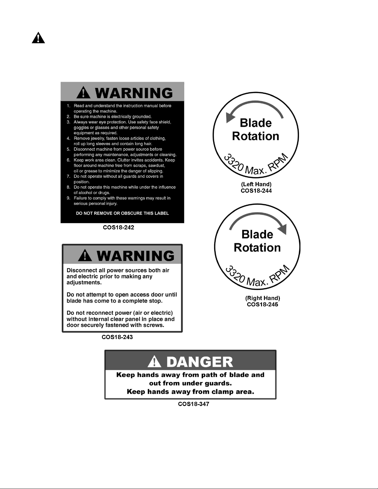
SAFETY
Familiarize yourself with the location and content of these decals on your machine.
FIGURE 1
6
Page 7

SPECIFICATIONS: COS18 Cut-Off Saw
Stock num ber (COS18L).....................................................................................................................1791294
Stock number (COS18R)....................................................................................................................1791289
Motor........................................................................................................................... .. 10HP, 3Ph, 230/460V
Blade size......................................................................................................................... 18" diameter / 120T
Arbor size.....................................................................................................................................................1"
Arbor speed.....................................................................................................................................3320 RP M
Cutting capac ity @ maximum height .......................................................................................4-3/8" x 10-1/2"
Cutting capac ity @ m aximum width ...............................................................................................1" x 13-3/8"
Table si ze....................................................................................................................................26-1/2" x 28"
Table hei ght................................................................................................................................................33"
Air supply r equired................................................................................................................. 15 CFM / 70 PSI
Cycles per minute (maximum)..................................................................................................................... 70
Dust port.......................................................................................................................................................4"
Minimum CFM........................................................................................................................................... 600
Gross weight........................................................................................................................................850 lbs.
Net weight ...........................................................................................................................................730 lbs.
NOTE: T he above specificati ons were current at the time this manual was published, but because of our
policy of continuous improvement, Powermatic reserves the right to change specifications without not ice and
without inc ur r ing obligations.
7
Page 8
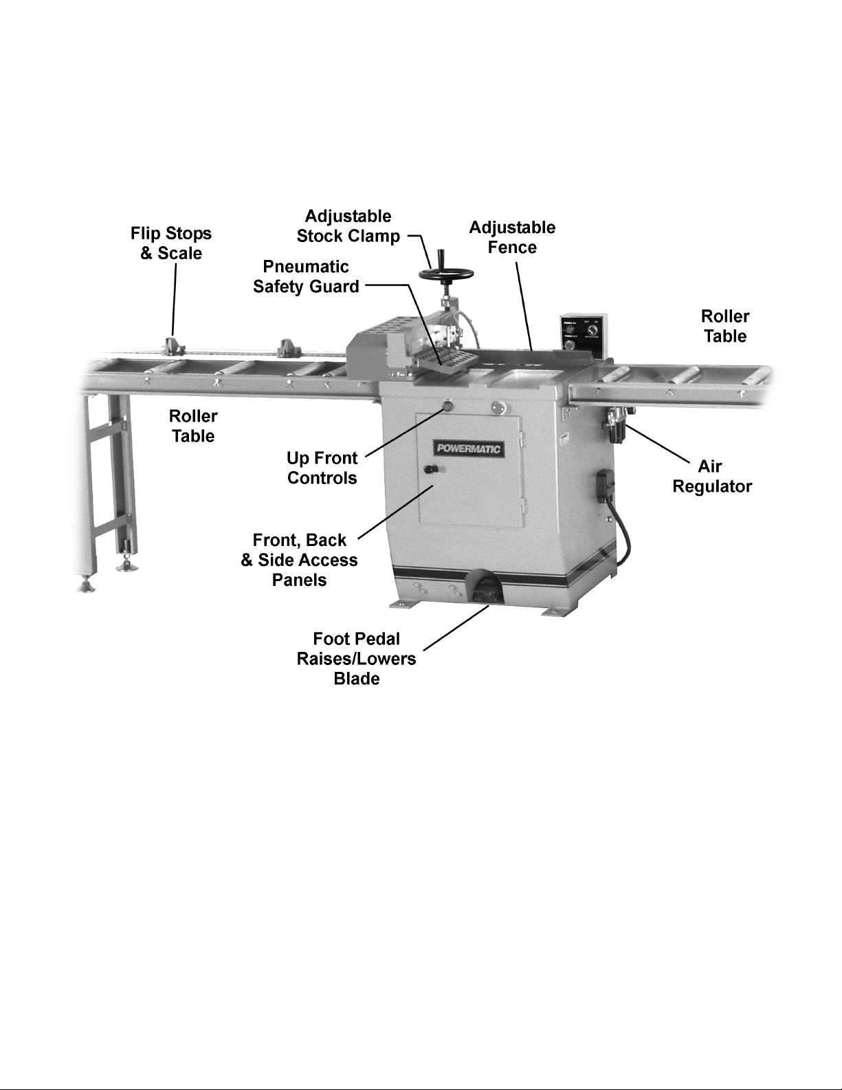
FEATURES: COS18 Cut-Off Saw
FIGURE 2
8
Page 9
RECEIVING
Open shipping crate and check for shipping
damage. Report any damage immediately to
your distri butor and shipping agent . Before using
the cut-off saw, read the instruction manual
thoroughly for assembl y, mai ntenance and safety
instructions.
Contents of crate:
1 Cut-off saw
1 Handwheel
1 Toolbox c ontaining:
1 hex wrench set
1 socket wrench
1 open-end wrench set
1 Manual
1 War ranty card
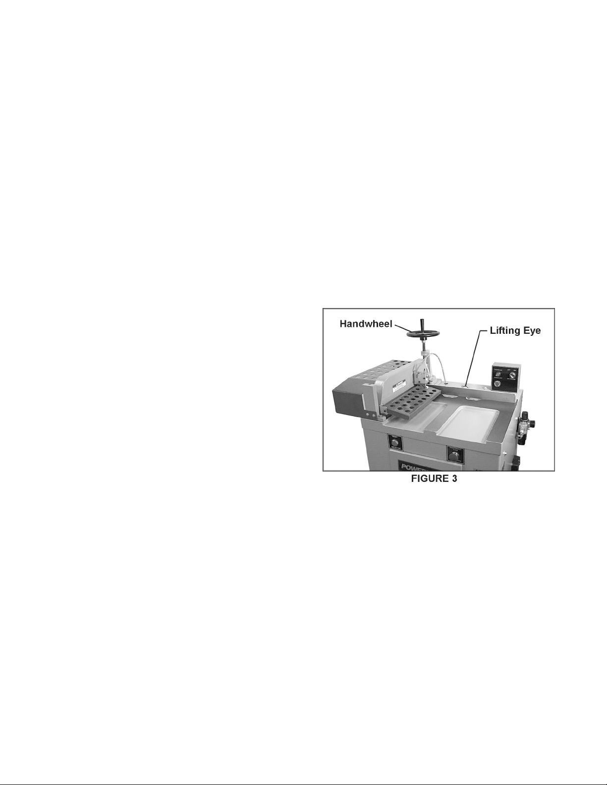
INSTALLATION & ASSEMBLY
1. Lift the m achi ne with a hoist or fork li ft , using
a sling through the lifting eye on top the
machine, shown in Figure 3. Mak e sur e the
capacity of the lifting unit is sufficient to
safely lift this size machine.
2. The cut-off saw (with any roller table
extensions) should be l ocat ed i n an area that
is well-lit, with enough room around it for
loading and off-loading stock and general
servi cing of the machine.
3. The saw cabinet should be bolt ed to the fl oor
through the holes at the four corners, using
high quali ty lag screws.
Unpainted surf aces, such as the table and f ence,
have been given a protective coating at the
factory. This should be removed with a soft rag
moistened with a good commercial solvent. Do
not use acetone, lac quer thinner, gasoli ne or any
flammable sol vents. Do not use an abrasi ve pad.
HANDWHEEL
Install the handwheel onto the threaded rod as
shown (Fig. 3).
9
Page 10
ELECTRICAL CONNECTIONS
WARNING: Electrical connectio ns must
!
be made by a qualified electrician in
compliance will all relevant cod es. The
machine must be properly grounded to
help prevent electrical shock and
possible death.
A power plug is not provided with the COS18.
You may either connect one, or "hard-wire" the
machine di rectl y to your elect rical panel prov ided
there is a disconnect near the machine.
Consult electrical schematic on page 34 for
further clarification of wiring setup.
This machine must be grounded. Grounding
provi des a path of least resistance t o help divert
current away from the operator in case of
electrical malfunction.
Make sure the voltage of your power supply
matches the specifications on the motor plate of
the machine.
After wiring, disconnect machine from power
source, open the blade access door, rem ove the
internal clear panel, and remove the blade (see
"Installing/Changing Blade"). Re-connect the
power and turn on t he saw motor (see "Oper ating
Controls"). Observe the rotation of the arbor – it
should rotate count erclockwise on the LH model,
clockwise on t he RH m odel . I f i t does not, tur n of f
the machine, disconnect power, and switch any
two of the thr ee electric al leads.
NOTE: A label is affixed to the internal clear
panel to help identify proper rotation.
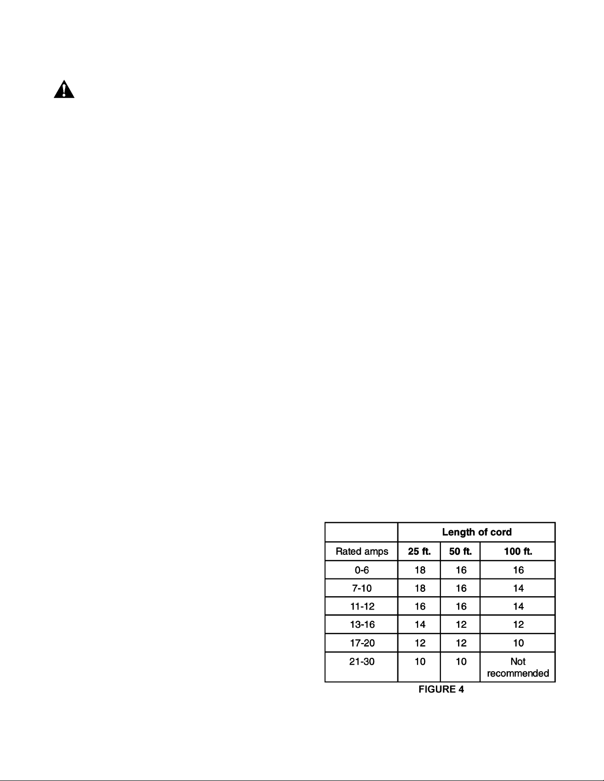
EXTENSION CORDS
If an ex tension cord is necessary, m ake sure the
cord rati ng is suitabl e for the amper age listed on
the machine's motor plate. An undersized cord
will cause a drop in line voltage resulting in loss
of power and overheating.
The chart i n Figure 4 shows the correct si ze cord
to use based on cord lengt h and nameplate am p
rating. If in doubt, use the next heavier gauge.
The smaller the gauge number, the heavier the
cord.
10
Page 11
DUST COLLECTION
Powermatic recommends the use of a dust
collection system with this cut-off saw. The
collector should have sufficient capacity (600
CFM) for this size machine.
Mount the dust collector via a 4" hose to the
outlet on t he blade access door.
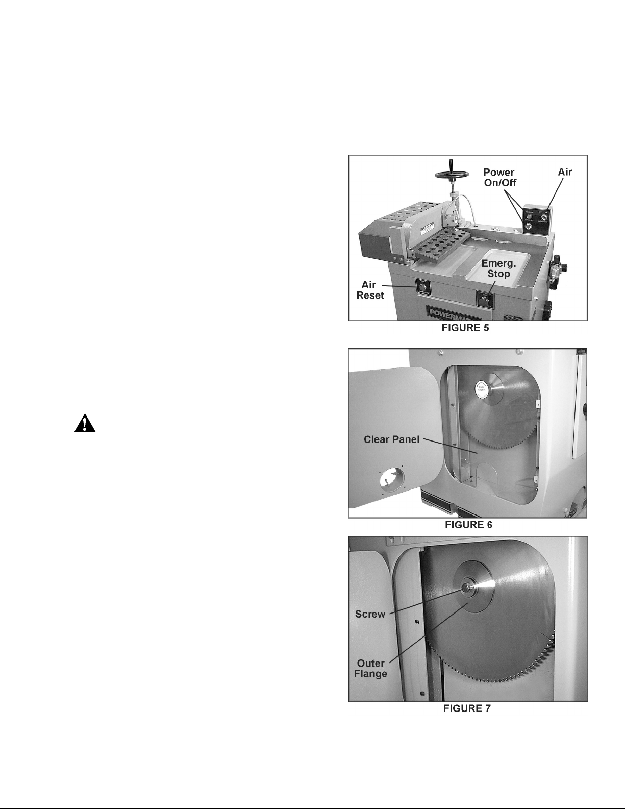
OPERATING CONTROLS
Control buttons are in two locations on the saw,
and are shown in Figure 5. A main start and stop
button i s located at t he back of the tabl e top. An
emergency stop but ton is also f ound on the front.
The air -cont rol switch, i n both l oc ati ons, start s the
flow of air to the cy linder.
INSTALLING / CHANGING BLADE
1. Disconnect machine from power source.
WARNING: Never attemp t t o open bl ade
!
access door until blade has come to a
complete stop.
2. Open the saw blade access door by
loosening the screws.
3. Remov e the clear panel guarding the blade
(Fig. 6) by loosening the screws and lifting
up on the panel.
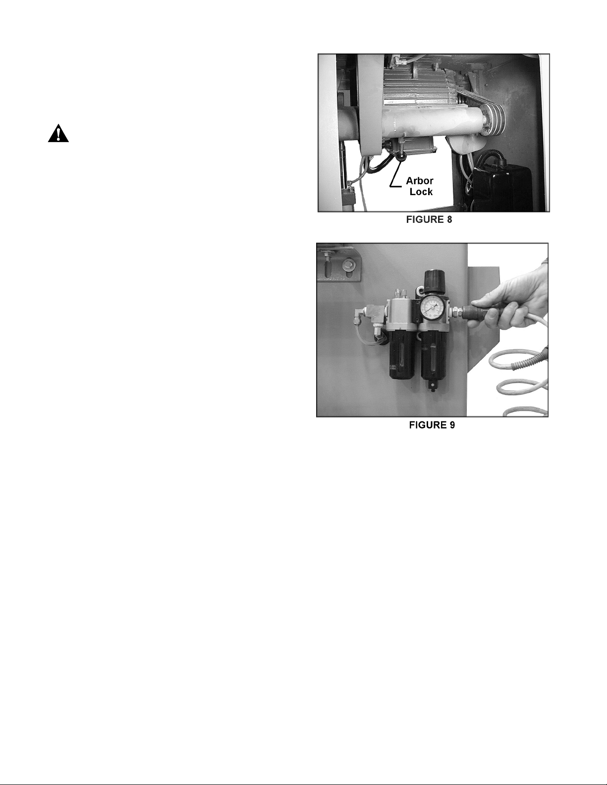
4. Lock the arbor by pulling the lever ( Fig. 8).
4. Loosen hex screw (Fig. 7) on the arbor.
(counterclockwise to loosen on the LH
model; clockwise on RH model). Remove
hex screw and outer flange from the arbor.
5. Mount the blade on the arbor as shown,
making sure the teeth are pointed in the
proper direction – the teeth at top of blade
should point toward rear of machine.
6. Re-install outer flange and screw, and
tighten securely.
11
Page 12
7. Re-install clear panel and c lose blade access
door, fasteni ng it securely. NO TE: A sensor
switch on the door will automatically shut
down the saw if the door i s opened whi le the
blade is moving.
WARNING: Do not reconnect power, air
!
or electric, without internal clear panel in
place and door securely fastened with
screws.
AIR SUPPLY
The correc t ai r pr essure for t he COS18 saw is 70
PSI. At tach the hose from your air source to the
machine' s air val ve as shown in Figure 9.
SQUARING THE FENCE
The best way to square the fence is to make
sample c uts. Using a square, check the end of a
board af ter it has been chopped. If the cut is not
square, proceed as follows:
1. Loosen one of the bolts on the fence and
lightly tap the fence with a block or mallet .
2. Retighten the bolt, and make another cut.
Repeat as necessary until fence is square.
INSTALLING ROLLER TABLES
(OPTIONAL)
Four-f oot and 8-f oot roll er tables are av ail able as
accessories to your cut- off saw. The roller tables
can be used as infeed or outfeed tables and
mounted to either side of the saw. The terms
"Right Hand" and "Left Hand" Model are
determined by the location of the blade in
reference to the main table. (The cover of this
manual shows a lef t-hand model. )
12
Page 13

To mount roller tables to saw:
1. Mount an angle bracket to the pre-drilled
holes in the side of the saw cabinet with four
M8 x 20 hex cap screws and four M8 flat
washers (Fig. 10). Do not fully tighten yet.
2. Place the roller table upside down on a flat
surface and attach the leg assemblies with
four M8 x 25 hex cap screws, eight M8 flat
washers, and four M8 hex nuts per leg
assembly (Fig. 11).
3. Screw an adjustable foot pad into each leg
as shown in Figure 12.
4. Flip the roller table ri ght-side up and mount it
to the angl e brack et on t he cabi net as shown
in Figur e 10. Use two M8 x 25 screws, four
M8 f lat washers and two M8 hex nuts. Do not
fully tighten y et.
13
Page 14

8-FOOT TABLE GUIDE
1. The 8-foot table comes with a guide and
scale. The guide should be mounted to the
edge of the table with six M8 x 27 square
head bolts, six M8 flat washers and six M8
hex nuts (Fig. 13).
2. Attach the three stops to the 8-foot table
guide (Fig. 13). These stops can be slid to
any point along the guide and secured by
tightening the lock l evers.
LEVELING & ALIGNING ROLLER TABLES
Each roller table must now be leveled with the
main saw table and aligned with t he fence. (The
fence m ust be square with blade – see "Squaring
the Fence", page 11.)
WARNING: Disconnect saw from both
!
air and elect ric power sou rces.
1. Select a piece of scrap board with a good
straight edge, 4 to 6 feet i n length.
2. Raise the blade guard and keep it raised.
Place t he board, straight edge down, on the
saw table surface and allow it to extend to
the second or third roller of the roller table
(Fig. 14).
3. Level the roller table by loosening the hex
nut on the f oot pad and screw the f oot pad in
or out. (see Fig. 12).
4. When roller table and main table are lev el,
tighten t he nuts on the foot pads.
14
Page 15

5. Now pl ace the board f lush against the f ence
and against the rail of the roller table(s). If
necessary, shif t a roller tabl e horizontally to
bring it in line wit h the fence.
6. When final adjustments have been made
and re-checked on the roller tables, tighten
all screws/nuts connecti ng t he rol ler tabl es to
the angle brackets.
CAUTION: Never adjust the outfeed
!
table level higher than the level of the
machine tab le surface.
ADJUSTMENTS
WARNING: Disconnect all power
!
sources, both air and electric, prior to
making adjustments.
BLADE TRAVEL
To adjust the speed by which t he saw blade (and
the cl amp) trav el up and down, open the cabi net
door and locate the upper and lower pressure
regulating valves which are attached to the air
cylinder (Fig. 15). Turni ng these will regul ate the
trav el speed of t he blade and clamp. The c lamp
will lower during the blade's upstroke, and rise
during the bl ade's downstroke.
The top valve (shown in Fig. 15) adjusts the
speed of the blade's downstroke (and the speed
of the cl amp as it rises back up). Turn the knob
counterclockwise to increase the speed, c lockwise
to decrease. W hen the speed is satisfact ory, lock
the setting by tightening t he knurled nut.
Repeat for the lower valve, which adjusts the
speed of the blade' s upstroke (and t he loweri ng of
the clamp).
CLAMP HEIGHT ADJUSTMENT
The distance between the stock clamp and the
workpiece can be adjusted by turning the
handwheel (Fig. 16). Line up the red indicator
plate with t he measurement on the scale. Ideall y,
there should be a space of 1/8" between the
clamp and the workpi ece. Aft er setting the c lamp
height, move the hex nut downward and tighten
against the casting as shown – this will prevent
your setting being altered by machine vibrations.
IMPORTA NT: The cl amp height adjustment m ust
be made each time the workpiec e si z e c hanges.
15
Page 16

BELT REPLACEMENT
1. Release tension on the v-belt and remove
old belt.
2. Make sure the new belt is properly situated
into the v-grooves of the pul ley.
3. Tension new belt.
OPERATION
WARNING: Do not place your hands
!
close to the guard/clamp at any time
during operations. All guards must be
install ed before using the machine.
1. St ar t the motor and the air supply.
2. Adjust height of clamp so it clears the
workpiece by about 1/ 8" .
3. Set the appr opri ate stop( s) on the rol l er tabl e
and load the stock on to the machine from
the infeed side.
4. When the stock is situated, press the foot
pedal to m ak e the cut.
WARNING: If the motor is shut off, but
!
the air is still on, the clamp will still be in
raised position. Turning off the air will
cause the clamp to lower suddenly. Keep
hands clear! Re-starting the air will cause
the clamp to rise suddenly.
MAINTENANCE
Frequently drain any water out of the pneumatic
valve.
The exposed met al areas on the table and f ence
should be kept clean and free f rom rust. A pply a
coat of paste wax as needed. Another option is to
briskly rub talcum powder into the surf ace with a
clean blackboard eraser.
Bearings should be greased thr ough the f itt ing on
the center of the arbor housing (F ig. 18).
16
Page 17

OPTIONAL ACCESSORIES - COS18 Cut-Off Saw
Part No. Descriptio n
6827037 ............. 8' Roller Table
6827038 ............. 4' RollerTable
6080157 ............. Blade, 18" 120T, 1" B or e
6080158 ............. Premium Blade, 18", 120T, 1" B or e
17
Page 18

PARTS LIST: Table & Motor Assembly (COS18 Cut-Off Saw)
Index Part
No. No. Descrip t ion Size Q t y.
1 ......... COS18-101L...........Casting Table (Left Hand)........................... .......................................... 1
1 ......... COS18-101R..........Casti ng Table (Right Hand) ........................ ..........................................1
2 ......... TS-1505051............Socket Head Cap Screw.............................M10x35.............................. 4
3 ......... TS-2361101............Lock W asher..............................................M10…………………………..4
4 ......... COS18-104 ............Bracket....................................................... ..........................................2
Φ
5 ......... COS18-105 ............Pin .............................................................
6 ......... BB-6204ZZ.............Ball Bearing................................................6204ZZ……….…………… . 2
7 ......... COS18-107............Spindle.......................................................……………………………… 2
8 ......... COS18-108L...........Spindle Frame (Left Hand) ......................... .......................................... 1
8 ......... COS18-108R..........Spindle Frame (Right Hand)....................... .......................................... 1
9 ......... TS-1523031............Socket Set Screw.......................................M6x10................................ 2
10 ....... TS-2211451............Hex Cap Screw..........................................M12x45.............................. 2
11 ....... TS-2360121............Fl at Washer................................................M12 ................................... 2
........... COS18-109L...........Spindle Assembly (Left Hand) (Items 12 thru 17 & 19 thr u 28)............... 1
........... COS18-109R..........Spindle Assembly (Right Hand) (Items12 thru 17 & 19 thr u 28) ............. 1
12 ....... COS18-112 ............Main Shaft Housing.................................... .......................................... 1
13 ....... COS18-113L...........Main Shaft.................................................. ..........................................1
13 ....... COS18-113R..........Main Shaft.................................................. ..........................................1
14 ....... BB-6206Z...............Ball Bearing................................................6206Z ................................ 2
15 ....... COS18-115L...........Spacer (Left Hand)..................................... .......................................... 1
15 ....... COS18-115R..........Spacer (Right Hand)................................... .......................................... 1
16 ....... COS18-116L...........Spacer (Left Hand)..................................... .......................................... 1
16 ....... COS18-116R..........Spacer (Right Hand)................................... .......................................... 1
17 ....... COS18-117 ............Spindle Collar............................................. .......................................... 1
18 ....... 6080157 .................Saw Blade..................................................
19 ....... COS18-119 ............Spindle Collar............................................. .......................................... 1
20 ....... COS18-120L...........Socket Head Cap Screw.............................M12x30 (L.H.).................... 1
20 ....... TS-1506031............Socket Head Cap Screw.............................M12x30 (R.H.)................... 1
21 ....... COS18-121 ............Key.............................................................7x7x50............................... 1
22 ....... COS18-122 ............Pulley......................................................... .......................................... 1
23 ....... COS18-123 ............Adapter ...................................................... .......................................... 1
24 ....... TS-1503061 ...........Socket Head Cap Sc r ew.............................M6x25................................ 3
25 ....... COS18-125 ............Special Pin................................................. .......................................... 1
26 ....... COS18-126 ............Locker........................................................ .......................................... 1
27 ....... COS18-127 ............Spring........................................................ ..........................................1
28 ....... COS18-128 ............Knob..........................................................W3/8”x30...........................1
29 ....... TS-1492031............Hex Cap Screw..........................................M12x35.............................. 2
30 ....... COS18-130L...........Bracket (Left Hand).................................... .......................................... 1
30 ....... COS18-130R..........Bracket (Right Hand).................................. ..........................................1
31 ....... TS-1503091............Socket Head Cap Screw.............................M6x40................................ 2
32 ....... TS-1550041 ...........Flat Washer................................................M6 .....................................6
33 ....... COS18-133 ............Fix Plate..................................................... ..........................................1
34 ....... TS-1540041............Hex Nut......................................................M6x1P............................... 6
35 ....... COS18-135 ............Limited Switch Seat.................................... .......................................... 1
36 ....... TS-1503041............Socket Head Cap Screw.............................M6x16................................ 2
39 ....... COS18-139 ............Limit Switch................................................ .......................................... 1
40 ....... COS18-140 ............Tube Fitt ings (L type) .................................1/8"x
41 ....... COS18-141 ............Silencer......................................................1/8".................................... 1
42 ....... TS-2284252............Pan Head Machine Scr ew ..........................M4x25................................ 3
6x30................................ 2
Φ
18”x25.4x120T................1
Φ
6..............................2
18
Page 19

PARTS LIST: Table & Motor Assembly (COS18 Cut-Off Saw) continued
Index Part
No. No. Descrip t ion Size Q t y.
43........ TS-1540021 ...........Hex Nut ..................................................... M4x0.7P.............................3
44........ TS-1491101 ...........Hex Cap Screw.......................................... M10x60 ..............................4
45........ TS-1550071 ...........Flat Washer............................................... M10....................................4
46........ COS18-146L..........Motor, 10HP, 3PH, 230/460V, 60Hz (LH)... ...........................................1
46........ COS18-146R .........Motor, 10HP, 3PH, 230/460V, 60Hz, (RH) ...........................................1
47........ TS-1540071 ...........Hex Nut ..................................................... M10x1.5P...........................8
48........ COS18-148 ............Key............................................................ 10x8x75 .............................1
49........ TS-1523031 ...........Socket Set Screw....................................... M6x10................................1
50........ COS18-150 ............Pulley ........................................................ ...........................................1
51........ COS18-151 ............Special Flat Washer................................... ...........................................1
52........ COS18-152L..........Socket Head Cap Screw............................ M10x30 (L.H)......................1
52........ TS-1505041 ...........Socket Head Cap Screw............................ M10x30 (R.H).....................1
53........ COS18-153 ............Socket Head Cap Screw............................ M6x16................................2
55........ COS18-155 ............Fix Plate .................................................... ...........................................1
56........ COS18-156 ............V-Belt ........................................................ 3V-1310.............................. 3
57........ TS-1506051 ...........Socket Head Cap Screw............................ M12x40 ..............................4
58........ TS-2361121 ...........Lock Washer.............................................. M12....................................4
19
Page 20

Table & Motor Assembly – Left Hand (COS18 Cut-Off Saw)
20
Page 21

Table & Motor Assembly – Right Hand (COS18 Cut-Off Saw)
21
Page 22

PARTS LIST: Stand Assembly (COS18 Cut-Off Saw)
Index Part
No. No. Descrip t ion Size Q t y.
1 ......... COS18-201L...........Stand (Left Hand)....................................... .......................................1
1 ......... COS18-201R..........Stand (Right Hand)..................................... .......................................1
2 ......... TS-1481041............Hex Cap Screw..........................................M5x16 ........................... 12
3 ......... TS-1550031............Flat Washer................................................M5 ..................................2
4 ......... COS18-204 ............Pedal S witch ..............................................230-8A............................1
φ
5 ........ COS18-205 ............Tube Fitt ings (I type) ..................................1/4"x
6 ......... COS18-206 ............Silencer......................................................1/4”.................................2
7 ......... COS18-207 ............Rubber Sleeve ........................................... .......................................1
8 ......... COS18-208L...........Front Door (Left Hand) ............................... .......................................1
8 ......... COS18-208R..........Front Door (Right Hand)............................. .......................................1
9 ......... COS18-209 ............Lock........................................................... .......................................1
10 ....... COS18-210 ............Key............................................................. .......................................1
11 ....... COS18-211 ............Emergency Button...................................... .......................................1
12 ....... COS18-212 ............Quick Fittings.............................................1/4”.................................1
13 ....... COS18-140 ............Tube Fitt ings (L type) .................................1/8"x
14 ....... COS18-214 ............Air Pressure Start Button............................ .......................................1
15 ....... COS18-215 ............Tube Fitt ings (T type) .................................1/8"x
16 ....... TS-1502021............Socket Head Cap Screw.............................M5x10……………………18
17 ....... COS18-217 ............Plate........................................................... .......................................1
18 ....... TS-2310051............Hex Nut......................................................M5x0.8P ………………….2
19 ....... COS18-219 ............Safety Cover, P.V.C................................... .......................................1
21 ....... COS18-221L...........Side Door (Left Hand)................................. .......................................1
21 ....... COS18-221R..........Side Door (Right Hand).............................. .......................................1
22 ....... TS-1502061............Socket Head Cap Screw.............................M5x25.............................2
23 ....... COS18-223 ............Exhaust Hood............................................. .......................................1
25 ....... COS18-225 ............Cover......................................................... .......................................1
28 ....... COS18-228L...........Air Filter (Oil Type) (Left Hand) ..................MACP300-10A................1
28 ....... COS18-228R..........Air Filter (Oil Type) (Right Hand)................MACP300-10A................1
29 ....... COS18-229 ............Ball valve...................................................1/4”.................................1
30 ....... COS18-230 ............Pressure Gauge ......................................... .......................................1
31 ....... TS-1550041............Fl at Washer................................................M6 ..................................2
32 ....... TS-1503041............Socket Head Cap Screw.............................M6x16.............................2
33 ....... COS18-233 ............Connection Bloc k .......................................3/8” .................................1
34 ....... COS18-234 ............Tube Fitt ings (L type) .................................3/8”x
35 ....... COS18-235 ............Tube Fitt ings (L type) .................................3/8”x
36 ....... COS18-236 ............Connection Board....................................... ...........……………………1
37 ....... TS-1532052............Pan Head Machine Scr ew ..........................M4x15.............................2
38 ....... COS18-238 ............Connection Box.......................................... .......................................1
40 ....... TS-1502101............Socket Head Cap Screw.............................M5x45.............................2
41 ....... COS18-241 ............Rubber Sleeve ........................................... .......................................2
42 ....... 3312341 .................Powermatic Logo Label.............................. .......................................1
43 ....... COS18-242 ............Warning Label............................................ .......................................1
44 ....... COS18-243 ............Warning Label............................................ .......................................1
45 ....... COS18-244 ............Rotation Blade L.H. Label........................... .......................................1
46 ....... COS18-245 ............Rotation Blade R.H. Label.......................... .......................................1
6...........................2
φ
6...........................2
φ
6...........................2
φ
10.........................1
φ
6...........................1
22
Page 23

Stand Assembly – Left Hand (COS18 Cut-Off Saw)
23
Page 24

Stand Assembly – Right Hand (COS18 Cut-Off Saw)
24
Page 25

PARTS LIST: Air Control Assembly (COS18 Cut-Off Saw)
Index Part
No. No. Description S ize Qty.
1..........COS18-301 .................Toggle Joint .......................................... ........................................... 1
2..........COS18-302 .................Shaft..................................................... ...........................................2
3..........COS18-303.................Cotter Pin.............................................. SSP-12...............................6
4..........TS-1540071 ................Hex Nut................................................. M10x1.5P...........................5
5..........COS18-305 .................Shock Absorber..................................... Tokico3243.........................1
6..........TS-1506131 ................Socket Head Cap Screw........................M12x80..............................1
7..........COS18-307 .................Ring...................................................... M12 ....................................2
8..........COS18-308 .................Nylon Ring............................................ M12....................................2
10........ TS-155108 ..................Lock Washer......................................... M12 ....................................1
11........ TS-1540081 ................Hex Nut................................................. M12x1.75P......................... 5
12........ COS18-312 .................Valve .................................................... ...........................................2
13........ TS-2284352 ................Pan Head Machine Screw ..................... M4x35................................4
14........ TS-1540021 ................Hex Nut................................................. M4x0.7P .............................4
φ
15........ COS18-140 .................Tube Fittings (L type) ............................ 1/8"x
16........ COS18-316 .................Plug ...................................................... 1/4"x10...............................1
17........ COS18-317 .................Tube Fittings (L type) ............................ 1/4”x
18........ COS18-141 .................Silencer................................................. 1/8”.....................................4
19........ COS18-319 .................Tube Fittings (T type) ............................ 1/4”x
20........ COS18-320 .................Tube Fittings (I type) ............................. 1/4”x
22........ COS18-322 .................Connector Bl oc k.................................... 1/8”.....................................2
23........ COS18-323 .................Nipple ................................................... 1/8”x1/8”............................. 2
24........ COS18-215 .................Tube Fittings (T type) ............................ 1/8"x
25........ COS18-325 ................Tube Fittings (L type) ............................ 1/4”x
26........ COS18-326 .................Switch Control Box................................ MS-P35..............................1
27........ TS-1533032 ................Pan Head Machine Screw ..................... M5x10................................4
28........ COS18-328 .................Toggle Joint .......................................... ........................................... 1
29........ TS-2310162 ................Hex Nut................................................. M16x1.5P...........................1
30........ COS18-330 .................Cylinder................................................. CB-50*230..........................1
31........ COS18-331 .................Jointer................................................... 1/4"x3/8".............................2
32........ COS18-332 .................Air Regulator......................................... 3/8” .....................................2
34........ COS18-234 .................Tube Fittings (L type) ............................ 3/8”x
35........ COS18-335L...............Swaying Arm (Left Hand)...................... ...........................................1
35........ COS18-335R ..............Swaying Arm (Right Hand).................... ...........................................1
36........ COS18-336 .................Special Pin............................................ ...........................................1
37........ COS18-337 .................Shaft..................................................... ...........................................1
38........ TS-2360121 ................Flat Washer .......................................... M12.................................... 4
39........ TS-0720111 ................Lock Washer ......................................... 1/2”.....................................3
40........ COS18-340L...............Bracket (Lef t Hand)............................... ...........................................2
40........ COS18-340R ..............Bracket (Right Hand)............................. ...........................................2
42........ TS-1491031 ................Hex Cap Screw..................................... M10x25..............................4
43........ TS-1551071 ................Lock Washer ......................................... M10....................................8
45........ COS18-345L...............Clamp Arm (Left Hand)......................... ...........................................1
45........ COS18-345R ..............Clamp Arm (Right Hand)....................... ...........................................1
46........ COS18-346 .................Limit Switch........................................... ...........................................1
47........ COS18-347 .................Danger Label......................................... ...........................................1
6...............................5
φ
6...............................1
φ
6...............................1
φ
10.............................2
φ
6...............................1
φ
10.............................1
φ
10.............................2
25
Page 26

Air Control Assembly – Left Hand (COS18 Cut-Off Saw)
26
Page 27

Air Control Assembly – Right Hand (COS18 Cut-Off Saw)
27
Page 28

PARTS LIST: Safety Guard Assembly (COS18 Cut-Off Saw)
Index Part
No. No. Descrip t ion Size Q t y.
1 ......... COS18-401 ................ Special Fixed Pin, guider....................... .......................................... 1
2 ......... TS-0561051................ Hex Nut.................................................1/2”-13...............................1
3 ......... COS18-403 ................ Rubber Cushion..................................... .......................................... 1
4 ......... COS18-404 ................ Knob...................................................... .......................................... 1
5 ......... COS18-405 ................ Handwheel............................................. .......................................... 1
6 ......... TS-1524021................ Socket Set Screw..................................M8x10................................ 1
7 ......... TS-0561081 ...............Hex Nut.................................................3/4”-10............................... 1
8 ......... TS-1491061................ Hex Cap Screw......................................M10x40.............................. 3
9 ......... TS-2361101................ Lock Washer .........................................M10 ................................... 3
10 ....... COS18-410 ................Depth scale............................................ .......................................... 1
11 ....... COS18-411 ................Support Seat.......................................... ..........................................1
12 ....... COS18-412 ................Donut, Red sign..................................... .......................................... 1
13 ....... COS18-413 ................Stopper.................................................. .......................................... 1
Φ
14 ....... COS18-414 ................Pin .........................................................
15 ....... COS18-415 ................Ring....................................................... .......................................... 1
16 ....... COS18-416 ................Lead Screw............................................ ..........................................1
17 ....... TS-1492041................ Hex Cap Screw......................................M12x40.............................. 2
18 ....... TS-2360121................ Flat Washer...........................................M12 ................................... 2
19 ....... COS18-419 ................Fence.................................................... .......................................... 1
20 ....... COS18-420 ................Control Box............................................ .......................................... 1
21 ....... TS-1482011................ Hex Cap Screw......................................M6x10................................ 2
22 ....... TS-1550041................ Flat Washer...........................................M6 ..................................... 9
23 ....... TS-1533042 ...............Pan Head Machine Screw......................M5x12................................ 4
24 ....... COS18-424 ...............Power On Button................................... .......................................... 1
25 ....... COS18-425 ...............Power Off Button................................... .......................................... 1
26 ....... COS18-140 ...............Tube Fit tings (L type).............................1/8"x
27 ....... COS18-427 ...............On/Off Air Control Swi tch ......................VM104............................... 1
28 ....... COS18-215 ...............Tube Fit tings (T type).............................1/8"x
29 ....... COS18-429 ...............Guider Seat ........................................... .......................................... 1
30 ....... TS-1482031 ...............Hex Cap Screw......................................M6x16................................ 3
32 ....... TS-1490051 ...............Hex Cap Screw......................................M8x30................................ 2
33 ....... TS-2361081 ...............Lock Washer .........................................M8..................................... 2
34 ....... COS18-434 ...............Limit Switch........................................... .......................................... 1
35 ....... COS18-317 ...............Tube Fit tings (L type).............................1/4”x
36 ....... COS18-436 ...............Silencer.................................................1/4” .................................... 1
37 ....... TS-2235991................ Socket Head Cap S c r ew........................M5x100.............................. 1
38 ....... COS18-438L...............Bracket (Left Hand)................................ .......................................... 1
38 ....... COS18-438R..............Bracket (Ri ght Hand) ............................. .......................................... 1
39 ....... COS18-439 ...............Spring Housing...................................... .......................................... 1
40 ....... COS18-440 ...............Spring.................................................... .......................................... 1
41 ....... TS-1540031 ...............Hex Nut.................................................M5x0.8P ............................ 2
42 ....... TS-1501091 ...............Socket Head Cap Screw........................M4x35................................ 2
43 ....... TS-1550021................ Flat Washer...........................................M4 ..................................... 2
44 ....... TS-1540021................ Hex Nut.................................................M4x0.7P ............................2
45 ....... TS-1481021................ Hex Cap Screw......................................M5x10................................ 6
46 ....... TS-1550031................ Flat Washer...........................................M5 ..................................... 2
47 ....... TS-1503041................ Socket Head Cap S c r ew........................M6x16................................ 2
48 ....... COS18-448 ................Bracket.................................................. .......................................... 1
49 ....... COS18-449 ................Bracket.................................................. .......................................... 1
52 ....... COS18-452 ................Special Rubber Head Screw..................W1/4"x25........................... 2
28
6x40................................ 1
φ
6.............................. 1
φ
6.............................. 1
φ
6.............................. 2
Page 29

PARTS LIST: Safety Guard Assembly (COS18 Cut-Off Saw) continued
Index Part
No. No. Descrip t ion Size Q t y.
53........ TS-1540041 ................Hex Nut................................................. M6x1P................................4
54........ COS18-454L...............Pneumatic Guard (Left Hand)................ ...........................................1
54........ COS18-454R ..............Pneumatic Guar d ( Right Hand) ............. ...........................................1
55........ COS18-455L...............Safety Cover (Left Hand) ...................... ...........................................1
55........ COS18-455R ..............Safety Cover (Right Hand).................... ...........................................1
58........ COS18-207 .................Rubber Sleeve...................................... ...........................................1
29
Page 30

Safety Guard Assembly – Left Hand (COS18 Cut-Off Saw)
30
Page 31

Safety Guard Assembly – Right Hand (COS18 Cut-Off Saw)
31
Page 32

PARTS LIST: 4' Roller Table Assembly (COS18 Cut-Off Saw) #6827038
Optional Accessory
Index Part
No. No. Description S ize Qty.
1 ......... COS18-501 ..............Roller Table............................................4’........................................1
2 ......... COS18-502 ..............Roller...................................................... ..........................................5
3 ......... COS18-503 ..............Split Pin .................................................. ........................................ 10
4 ......... TS-1490021 ..............Hex Cap Screw.......................................M8x16................................ 8
5 ......... TS-1550051...............Flat Washer............................................M8 .....................................8
6 ......... COS18-506 ..............Bracket.................................................... ..........................................1
9 ......... TS-1540061 ..............Hex Nut...................................................M8x1.25P .......................... 6
10 ....... COS18-510 ..............Leg.......................................................... .......................................... 1
14 ....... TS-0561071 ..............Hex Nut...................................................5/8”-11............................... 2
15 ....... COS18-515 ..............Adjusting Foot.........................................5/8"....................................2
32
Page 33

4' Roller Table Assembly (COS18 Cut-Off Saw) #6827038 Optional Accessory
33
Page 34

PARTS LIST: 8' Roller Table Assembly (COS18 Cut-Off Saw) #6827037
Optional Accessory
Index Part
No. No. Description S ize Qty.
1 ......... COS18-601 ..................Guide Rail............................................8’........................................1
2 ......... COS18-602 ..................Scale....................................................2400mm.............................1
3 ......... COS18-603 ..................Pan Head Machine Screw....................M5x5..................................2
4 ......... TS-1550031..................Flat W asher.........................................M5 .....................................2
5 ......... COS18-605 ..................Guide Body.......................................... ..........................................3
6 ......... COS18-606 ..................Square Head Bol t.................................M8x 40…………………….....6
7 ......... COS18-607 ..................Lock Handle......................................... .......................................... 6
8 ......…TS-1550051..................Flat Washer .........................................M8 ................................... 24
9 ......... COS18-609 ..................Guide Stopper...................................... ..........................................3
Φ
10 ....... COS18-610 ..................Spring Pin............................................
11 ....... COS18-611 ..................Squar e Head B olt.................................M8x27................................6
13 ....... TS-1540061..................Hex Nut................................................M8x1.25P ........................ 19
14 ....... TS-1490041..................Hex Cap Screw....................................M8x25................................3
16 ....... COS18-616 .................Roller Table .........................................8’........................................1
17 ....... COS18-502 .................Roller................................................... ........................................ 11
18 ....... COS18-503 .................Split Pin ............................................... ........................................ 22
19 ....... TS-1490021..................Hex Cap Screw....................................M8x16..............................12
21 ....... COS18-506 ..................Bracket ................................................ .......................................... 1
25 ....... COS18-510 .................Leg....................................................... .......................................... 2
29 ....... TS-0561071 .................Hex Nut................................................5/8”-11............................... 4
30 ....... COS18-515 ..................Adjusting Foot......................................5/8"....................................4
3x30................................3
34
Page 35

8' Roller Table Assembly (COS18 Cut-Off Saw) #6827037 Optional Accessory
35
Page 36

PARTS LIST: Pneumatic Diagram (COS18 Cut-Off Saw)
Index Part
No. No. Description S ize
1 ......... COS18-211 ................ Emergency Button.................................
φ
2 ......... COS18-140 ................ Tube Fitt ings (L type).............................1/8"x
3 ......... COS18-215 ................ Tube Fitt ings (T type).............................1/8"x
4 ......... COS18-214 ................ Air Pressure Start Button .......................
5 ......... COS18-215 ................ Tube Fitt ings (T type).............................1/8"x
6 ......... COS18-140 ................ Tube Fitt ings (L type).............................1/8"x
7 ......... COS18-140 ................ Tube Fitt ings (L type).............................1/8"x
8 ......... COS18-140 ................ Tube Fitt ings (L type).............................1/8"x
9 ......... COS18-322 ................ Jointer Block..........................................1/8”
10 ....... COS18-323 ................Jointer...................................................1/8”x1/8”
11 ....... COS18-322 ................Jointer Block..........................................1/8”
12 ....... COS18-215 ................Tube Fit tings (T type).............................1/8"x
13 ....... COS18-323 ................Jointer...................................................1/8”x1/8”
14 ....... COS18-320 ................Tube Fit tings (I type)..............................1/4”x
15 ....... COS18-320 ................Tube Fit tings (I type)..............................1/4”x
16 ....... COS18-312 ................Connector..............................................
17 ....... COS18-140 ................Tube Fit tings (L type).............................1/8"x
18 ....... COS18-141 ................Silencer.................................................1/8”
19 ....... COS18-325 ...............Tube Fit tings (L type).............................1/4”x
20 ....... COS18-141 ................Silencer.................................................1/8”
21 ....... COS18-312 ................Connector..............................................
22 ....... COS18-317 ................Tube Fit tings (L type).............................1/4”x
23 ....... COS18-140 ................Tube Fit tings (L type).............................1/8"x
24 ....... COS18-141 ................Silencer.................................................1/8”
25 ....... COS18-319 ................Tube Fit tings (T type).............................1/4”x
26 ....... COS18-141 ................Silencer.................................................1/8”
27 ....... COS18-140 ................Tube Fit tings (L type).............................1/8"x
28 ....... COS18-204 ................Pedal Switc h..........................................230-8A
29 ....... COS18-206 ................Silencer.................................................1/4”
30 ....... COS18-205 ................Tube Fit tings (I type)..............................1/4"x
31 ....... COS18-205 ................Tube Fit tings (I type)..............................1/4"x
32 ....... COS18-330 ................Cylinder.................................................CB-50*230
33 ....... COS18-332 ................Air Regulator .........................................3/8”
34 ....... COS18-234 ................Tube Fit tings (L type).............................3/8”x
35 ....... COS18-331 ................Jointer...................................................1/4"x3/8"
36 ....... COS18-332 ................Air Regulator .........................................3/8”
37 ....... COS18-234 ................Tube Fit tings (L type).............................3/8”x
38 ....... COS18-331 ................Jointer...................................................1/4"x3/8"
39 ....... COS18-317 ...............Tube Fit tings (L type).............................1/4”x
40 ....... COS18-436 ...............Silencer.................................................1/4”
41 ....... COS18-434 ...............Limit Switch...........................................
42 ....... COS18-317 ...............Tube Fit tings (L type).............................1/4”x
43 ....... COS18-140 ...............Tube Fit tings (L type).............................1/8"x
44 ....... COS18-427 ...............On/Off Air Control Swi tch ......................
45 ....... COS18-215 ...............Tube Fit tings (T type).............................1/8"x
46 ....... COS18-228(R/L)......... Air Filter (Oil Type)................................MACP300-10A
47 ....... COS18-212 ................Quick Fittings.........................................1/4”
48 ....... COS18-229 ................Ball valve ..............................................1/4”
49 ....... COS18-233 ................Connection Block...................................3/8”
36
6
φ
6
φ
6
φ
6
φ
6
φ
6
φ
6
φ
10
φ
10
φ
6
φ
10
φ
6
φ
6
φ
6
φ
6
φ
6
φ
6
φ
10
φ
10
φ
6
φ
6
φ
6
φ
6
Page 37

PARTS LIST: Pneumatic Diagram (COS18 Cut-Off Saw) continued
Index Part
No. No. Description S ize
φ
φ
Φ
Φ
6
10
6
6
50........ COS18-235 .................Tube Fittings (L type) ............................ 3/8”x
51........ COS18-234 .................Tube Fittings (L type) ............................ 3/8”x
52........ COS18-141 .................Silencer................................................. 1/8"
53........ COS18-140 .................Tube Fittings (L type) ............................ 1/8"x
54........ COS18-140 .................Tube Fittings (L type) ............................ 1/8"x
55........ COS18-139 .................Limit Switch...........................................
37
Page 38

ELECTRICAL SCHEMATIC (COS18 Cut-Off Saw)
38
Page 39

Preventive Maintenance
Checklist for Model COS18 Cut-Off Saw
[ ] W or k ar ea around machine marked off clearly.
[ ] Non-skid f loor strips in area where operat or nor mally stands.
[ ] Inspect enti r e machine for loose bolts, nuts, screws. Tighten and replace as necessary.
[ ] Clean tabl e ar ea, removing sawdust and chips with a soft br istle brush. Remove gum and pitch
with ov en cleaner.
[ ] Lubricate appr opr iate places with a good grade non- har dening grease.
[ ] Clean tabl e and fence surface. If rusted, use paste mixtur e of household ammonia, a good commercial
detergent and 000 steel wool . Wash surf ac e down with hot , soapy water, rinse and dry thoroughly.
Coat surface with talcum powder, r ubbing briskly into surface with a c lean blackboard eraser.
[ ] Check blade condition; should be sharp and free of ni c ks or grooves.
[ ] Check belt c ondition. Replace as needed. Dress with belt dressing. Check belt tension.
[ ] Check mot or for loose wiri ng and sawdust congestion, pulleys tight and in line.
[ ] Check bearings. Replace any bad or suspect bearings immediat ely.
[ ] Fence properl y aligned and square.
[ ] Foot pedal has proper adjustment.
[ ] Check elect r ical controls function and pneumatic guard operation.
[ ] Check ali gnment of r oller tabl es wit h main tabl e.
To order parts or reac h our service department, please call our toll-fr ee number between 8:00 a.m . and 4:30
p.m. ( C S T), Monday through F r iday. Having the Model Number and Serial Number of y our machine available
when you call will allow us to serve you quickly and accuratel y . Locating the stock number of t he par t(s)
required from your parts manual will also expedite your order.
Phone No.: (800) 248- 0144
Fax No. (800) 274-6840
If you ar e c alling from Canada, please call 800-238-4746
E-mai l: powermatic@wmhtoolgr oup.com
Website : www.powermatic.com
39
Page 40

40
WM H Tool Group
427 Sanford Road
LaVergne, TN 37086
Phone:(800) 248-0144
Fax: ( 800) 274-6840
E-mai l: powermatic@wmhtoolgr oup.com
Website : www.wmhtoolgroup.com
 Loading...