

Page 1
Model
1150=
MAINTENANCE
AND PARTS LIST
15"
(381
mm)
Drill
Press
INSTRUCTIONS
/
Better
McMINNVILLE,
,_.
.~
By
TENNESSEE
.-
..
~
-
Design@
®Iiii®
e15·473
5;;51
'Z-l1~
37110 0
.
.
AC
CC/JO
;
0/'1
III
7
Page 2
FORWORD
SAFETY
This
Model
safety
before
FI
manual
1150
through
operating
RST
has
A
Drill
the use
In order to obtain
ions
in
the operating instructions and maintenance manuals carefully.
The
specifications
Powermatic's
time
without
This
(blades.
of
component
policy
obligation
Powermatlc,
its
authorized
manufactured
of
delivery
date
Powermatfc
period.
This
maintenance
becomes
days
from
warranty
lubricants.
removal.
effective
date
been prepared
Press..
of
the
machine
maximum
put
forth in this manual were in effect at the time
of
continuous
on
for
the
Its
owner
purpose
and those responsible
aside from
proper
accepted practice.. Read the
..
life and efficiency
improvement,
the
part
of
Powermatic.
from
your Powermatic
changes
WARRANTY
a DIvision
by
wilt, at Its
warranty
and
does
shipment
manufacturer's
of
dIstributors
from
of
DeVlfeg-Bullard Inc.,
of
Powennatlc
its authorized distributors
option,
applies
safety set
only
if
delivery
not
etc.);
for
Powermatlc
to
repair
only
forth
the
accompanying
to
the
apply
to
to
el~trtcal
service
local
be free
Morrison
products
of
defects In material and
or
replace
to
products
In the catalogs, manuals,
original
items
and
aulhoflzed
card
purchaser.
that
would
motors
and
reinstallation.
repair
and
or
2000
hours
any
product
which
Is fully
and
normany
components
Claims
station
Road,
the
are
and/or
properly
be
for
of
(or
used
relating
maintenance
safety
to
these specifications
McMinnville,
original
consumed
which
service.
purchasers
workmanship
use,
whichever
component
In
accordance
Instruction
completed
are
to
for
the
maintenance
and
operations
and
operating
Drill
of
publication. However, owing
Tennessee 37110 ("Powermatlc") warrants to
or
warranted
electracal
for
for
a perfod
occurs
part thereof) proving defective
with
sets furnished
and returned to
require
replacement
by
components
instructions
Press
such distributors, all
of
twelve (12)
first.
During
all instructions
by
Powermatlc. This warranty
PowermatIc
their
manufacturer;
must
follow
may
months
said
warranty
as
due
to
be
of
a Powermatic
is
to
thoroughly
all the instruct-
be
made
products
from
during
to operation,
within
ten (10)
normal
or
the
taken
to
promote
at
the
period
said
wear
costs
the
to
any
ORr
LL
Read
1.
limit~tions
belt
ThIS
warranty
(2)
accident,
tampeflng.
bea"ng
repaffs
To
obtaIn
from
whom
product
proof
of
dIrectly
how
and
provided
returned
to
repalrtng
delIvery.
shall
Powermat,c's
THIS IS
BY
LAW.
HEREBY
LOSS,
DAMAGE. OR EXPENSES DIRECTLY
OTHER
VENIENCE.
OTHER
PRESS
understand
guard
is
null
neglect.
alterations
,ts
anginal
required
the
you
was
delIvered
purchase.
If
your
v.here
to
alfow
Without
or
FOB.
POWERMATIC'S
INCLUDING
LIMITED
CAUSE
AND
WARRANTY.
SAFETY
and
damage
or
serial
due
to
natural
fastest
possible
purchased
to
Should
claim
IS
covered
service
WIll
correctIon
I[S
pnor
replac,ng
(return
OR FOA CONSEQUENTIAL
(at
freight
liability
ANY
TO THE
lOSS
OF PRODUCTION). THE
EXPRESS OR
INSTRUCTIONS
and
and
hazards
of
this
machine
void
repairs
number
you,
Cl(cumstances
wrttten
SOLE
WARRANTIES
DURATION
follow
if
the
product
Of'
other
outs,de
plate.
causes
warranty
the
product
(3)
a
description
by
thIs
be·provtded.
by
customer
authortzat.on.
Powermat,c·s
patd
by
under
this
WRIITEN
OF THIS
IMPUED.
the
associated
to
serve
has
circumstances
of
This
or
service
SpecifYing
warranty.
On
customer)
warranty
WARRANTY.
safety
been
P(YNermat'c·s
warranty
acts
of
God.
you
(')
of
the
prohibit
personnel.
option)
FOR
you
your
simple
Powermatic's
products
Powermat,c's
exceed
MERCHANTABILITY
WRITIEN
OR
INDIRECTLY
DAMAGES
WARRANlY
SHALL
and
with
a 1
as a reminder
subjected
beyond
factory
does
not
must
first
the
problem
warranty
Powermatlc
ANY
BE
notIfy
product
for
contacting
Powermat,c
replacement
obligatIon
whIch
the
purchase
AND
WARRANTY.
RELATED
(INCLUDING
CONTAINED
MADE
operating
150
A Drill Press. A
of
basic
to
(1)
misuse.
Powermatic's
nor
authorized
apply
to
in
writing
by
catalog
which
the
dlstflbutor
dIstrIbutor
assumes
under
are
determined
factory.
and
prace
ALL
OTHER
OR FITNESS FOR A PARTICULAR PURPOSE. ARE
POWERMATIC
TO
WlTHOUT
BY OR ON BEHALF OF
instruction
safety
control;
normal
number
you
seek
Will
or
repairs.
no
thlswarranty
on
inspection
paid
WARRANTIES
THE
USE
HEREIN
safety
practice.
abuse
Of
improper
(3)
by
'Near
the
warranty
then
responsibilIty
by
for
LIMITATION.
modifications.
Powermat,c;
and
tear.
authorized
and
serial
contact
provide
installatIons
Powermatic
by
the
product.
SHALL
OFITS
PRODUCTS OR
MAY
NOT
POWERMATIC.
found
rules decal
or
corrosion.
Powermatic
number.
servIce.
the
Pow-ermatlc
you
WIth
for
pr<X1ucts
shall
be
to
Powermatlc.
VVHICH
NOT BE
lOSS
BE
MODIFIED
in
this
service
or
disassembly
to
any
product
abrasion.
distributor
(2)
the
and
(4)
eVIdence
InstructIons
instructions
whIch
exclUSIvely
be
defectIve
In
MAY
BE
llABLE
FROM
OF TIME.
manual..
is
installed
storage;
not
date
the
factory
as
WIll
are
limIted
upon
no
event
IMPLIED
FOR
ANY
ANY
INeON·
AND
NO
Know
or
of
to
be
on
the
the
2.
Grounding
grounding
used,
make
cedu re
indicated
the
drill press: Make certain
lead
is
certain
by
included
that
the
in
the
grounding
National
the
incoming
Electric
that
lug
Code.
the machine frame
electrical
connects
service.
to
a suitable
is
electrically
In
cases
ground.
grounded and
where a cord and
Follow
the
grounding
that
plug
a
are
pro-
Page 3
-------
--
3. Eye Safety: Wear
the
drill
press.
an
approved safety face shield, goggles or glasses to protect eyes
when
operating
4. Personal Protection:
roll up sleeves above the elbow. Remove
type
footwear
should
exposure allowed
5.
Work Area:
Keep
other foreign material, and
sure the table
is
Before operating the machine, remove tie, rings, watch and
all
outer
loose clothing and confine long hair. Protective-
be
worn.
in
Section 1910.95
the floor around the machine clean and free
free of chips, tools and everything
r1@aring
protectors
of
the OSHA regulations. Do Not Wear Gloves.
oil, grease or coolant
shoufd
to
minimize the danger of tripping or slipping.
else
be
used
where
of
tools, tooling, stock scrap and
not
required for the task to be performed.
Powermatic recommends the use of anti·skid floor strips on the floor area where the
ally stands and
lighted and ventilated. Provide for adequate work space around
6.
Guards: Keep
that
each machine's work area be marked off. Make certain the work area
the
machine.
all
machine guards
in
place at
a~1
times when
the
machine
the Machine with the Guard Off.
7.
Do
Not
Overreach: Maintain a balanced stance and keep
8.
Maintain Tools in
Top
Condition: Keep tools sharp and clean for safe and best performance.
tools can increase the feed force required and can result
the
work
to
be pulled free from its holding device. Dull
duce a straight hole.
9.
Use
the Proper Speed and Feed: A table
in
selecting the correct speed and feed rate for a variety of materials.
suit the material supplier for correct speed
is
provided
and feed rate. Adjust speed on variable speed models
only with the power on. On step cone models, make sure power
a complete stop before opening the access
door
to
your
body
in
burning the stock
or
improperly sharpened drills will
in
the operating instruction manual
change speeds.
under control at all times.
For
is
off and
other
jewelry and
noise exceeds the
operator
is
in
use.
Do
Not
or
seizing up, causing
materials
the
not
shown, con·
spindle has come to
level
Be
norm
is
well
Operate
Dull
not
pro·
as
a guide
of
..
10. Never Drill Freehand: Always block
causing
the
work piece, jig,
or
fixture
11. Remove Key Chucks: When a key chuck
lock a tool
chuck and could result
in
the chuck. If
it
is
in
serious injury.
or
clamp
to
rotate
is
not
removed, starting the spindle can cause
the
work piece. A drill
with the spindle and can cause serious injury.
used, remove
12. Hand Safety: Keep hands away from the spindle when
is
chips when the spindle
under power and never use
rake. Chips are razor sharp and can
cause serious
the
injury.
Rotating Under Power.
13. Spindle Rotation:
14. Machine Adjustments: Make all machine
speed model
15. Machine Capacity: Do Not
requiring more than the rated horsepower
life
of
the machine and could cause the breakage
16. Avoid Accidental Starting: Make certain
power to
the
Be
sure
the
rotation
of
the
spindle
is
adjustments
or
feed rate on machine equ ipped with power feed. .
attempt
to
use
the
machine beyond its stated
of
the
motor. This
of
parts which could result
the
motor
switch
machine.
bit
or
tap can seize up
it
immediately
the
machine
after using
is
under
it
to
lock
it
to
be
thrown
off the
power. Never clear
hands to clear chips; use a brush or chip
Do Not Change Tools
correct for
with
is
the
power off
type
use
in
the
"off"
tool being used.
except
capacity
witl
position before connecting
with
the
speed
reduce
in
personal injury.
on
or
for operations
the
Spindle
a variable
productive
or
un-
17. Careless Acts: Give the work you are doing
a conversation, and "horseplay" are careless acts
your
undivided attention. Looking
that
can resu
It
in
serious inju ry.
around,
carrying on
3
Page 4
18.
Job
Completion:
turned
is
and never clean chips
off
complete, he should clean the machine and
and
the
If
the
spindle
with
operator
come
the hands;
leaves
the
machine area
to a complete
use
a brush
for
any reason,
stop
before he departs. In addition,
work
area.
Never clean the machine
or
chip rake.
the
drill press should
if
the
with
be
operation
power on
19. Disconnect Machine: Before
20.
Replacement
otherwise,
21. IVlisuse:
Parts: Use
the
drill
Do
Not
poses, Powermatic disclaims any real
that
may
result
power
in
Spindle
Quill
Column Outside
Column Wall
Column
Column Length, Bench
Travel.
Diameter.
Length,
Table Working
Utility
Tilting
Production
Table
Table
Base Working
Capacity
Capacity
Throat
Spindle
Variable
Step
Weight
in
in
Depth
Speeds
1800 R
1200 RPM
Pu
tley Models
1800
RPM
1200
RPM
Nets.
nor
writing
. . .
. . . .
Diameter
Thrickness
Floor
Surface
Table.
Surface
Cast I
ron
Steel "
. " " .
Speed Models
PM
Motor
Motor
Motor
Motor
" " .
from
with
a
by
Powermatic.
..
.
Model .
Model.
. . . .
.
. .
. . . .
performing
only
press
warranty
use
the
1150 A Drill
the
use.
motor
with
. .
..
. . . . . . . .
any service
Powermatic
or
factory
or
maintenance.
authorized
and guarantee will be null and void.
Press
for
other
than its
or
Do
Not
a speed
implied
equip a 1150 A
greater
SPECI
warranty
Drill
than
1800
FICATIONS
and holds itself harmless
Press
rpm unless specifically
replacement
intended
with a motor
use.
parts
and accessories;
If used
for
other
for
any
larger than 1 horse-
authorized
" .
.. . 6"
·
2-3/16"
. .
· .
3/16"
66"
42"
. .
10"
x
11"
(254 x
.. . 10"
.
x
12" x 18"
13"
x
15Y2"
14"
(254
(305 x 457mm)• e • • •
(330 x 394mm)
· .
5/8"
1/2"
g
450-4800
300 -3200
. . 400 - 840
260 -560 -1050 -1875 -3550
c • • • • " • " " " • •
..
1580 -2800 - 5300 R
pur-
injury
to
do
so
(152mm)
(55.6mrn)
3"
(76mrn}
(4.8mrn)
(1676mrn)
(1
067mrn)
279mm)
x 356mm)
(15.9mm)
(12.7mm)
7Y2"
(190mm)
See Catalog
RPM
RPM
PM
RPM&
Page 5
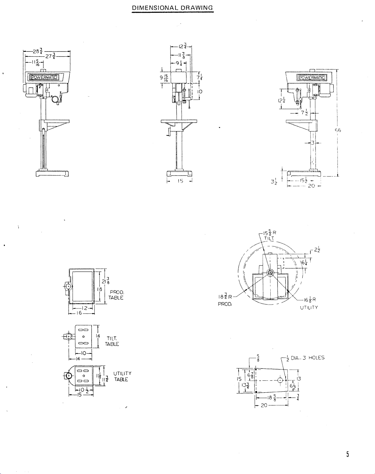
DIMENSIONAL
DRAWING
7'
-
-(
, I
I
10
:~
I'
i
! I
--11~
r-
I I
,
f--
--
;-.-_...
~~
J
15 ~ - •
_.
20
-
t-o:=
]~ !
r
I
i
I
So
I
I
1-
~_-,"*J
~~~¥
12~1
16~
c)c)
+ 0
I
=J
I l
10-1
~14
----1
II
21~
8
PhDD.
TABLE
11
I
14
TILT.
TABLE
18~R
PROD.
UTILITY
TABlE
5
Page 6
MACHINE
INSTALLATION
RECEIVING:
ADJUSTMENTS
AND
MAINTENANCE
Remove
immediately.
and spindle
drill
press
from
shipping container and check
Attach
with
accessories shipped
a good commercial solvent. Read
maintenance and safety instructions.
I
NST
ALLATI
Mount
and table
head
available
1.
Place a·brock
2.
Loosen head
3.
Turn
4.
Lock
through
5. If the above procedure
lift
6.
After
the head.
ON:
machine on a solid
of
the machine have been lowered on
to
raise
the
head, proceed
of
wood
locking
handle
head again
counter
handles,
- clockwise (toward the
with
4.
head and one
head
is
This
to
at
proper
will
prevent head
handle loosening and
foundation
as
between spindle nose and
bumping
Jacking handles, raise table
is
too
slow,
height - - secure
with
drill
and
lag
follows:
them lightly
use a minimum
locking
tightly,
from
falling
press,
instruction
to
the
floor
the
top
operator).
to a position
the head locks
then
if
loosened
for
damage.
then
clean
Report
protective
manual
through
column
of
table.
to
make certain
Head
of
three men
make sure the safety
for
holes
for
convenience in packaging. If a crane
they
will
move
just
under
to
..
swing drilling operations.
any damage
coating
thoroughly
provided
release.
upward
spindle nose and repeat steps 2
move
head
collar
in
6""
to
to
your
from
table,
for
assembly alignment,
base
of
drill
its
proper
is
locked
height;
in
distributor
column,
press. The
is
two
place
under
base
not
to
Visually
7.
MULTIPLE
In the
assemble the
supports and
more than one piece.
guarantee alignment
precision level and level using the
in
MOTOR
Step Pulley
case
legs.
If
your
installation
a.
b.
c.
align spindle
SPINDLE
of
multiple
legs
bolt
INSTALLATION:
Models-
machine was ordered
easier.
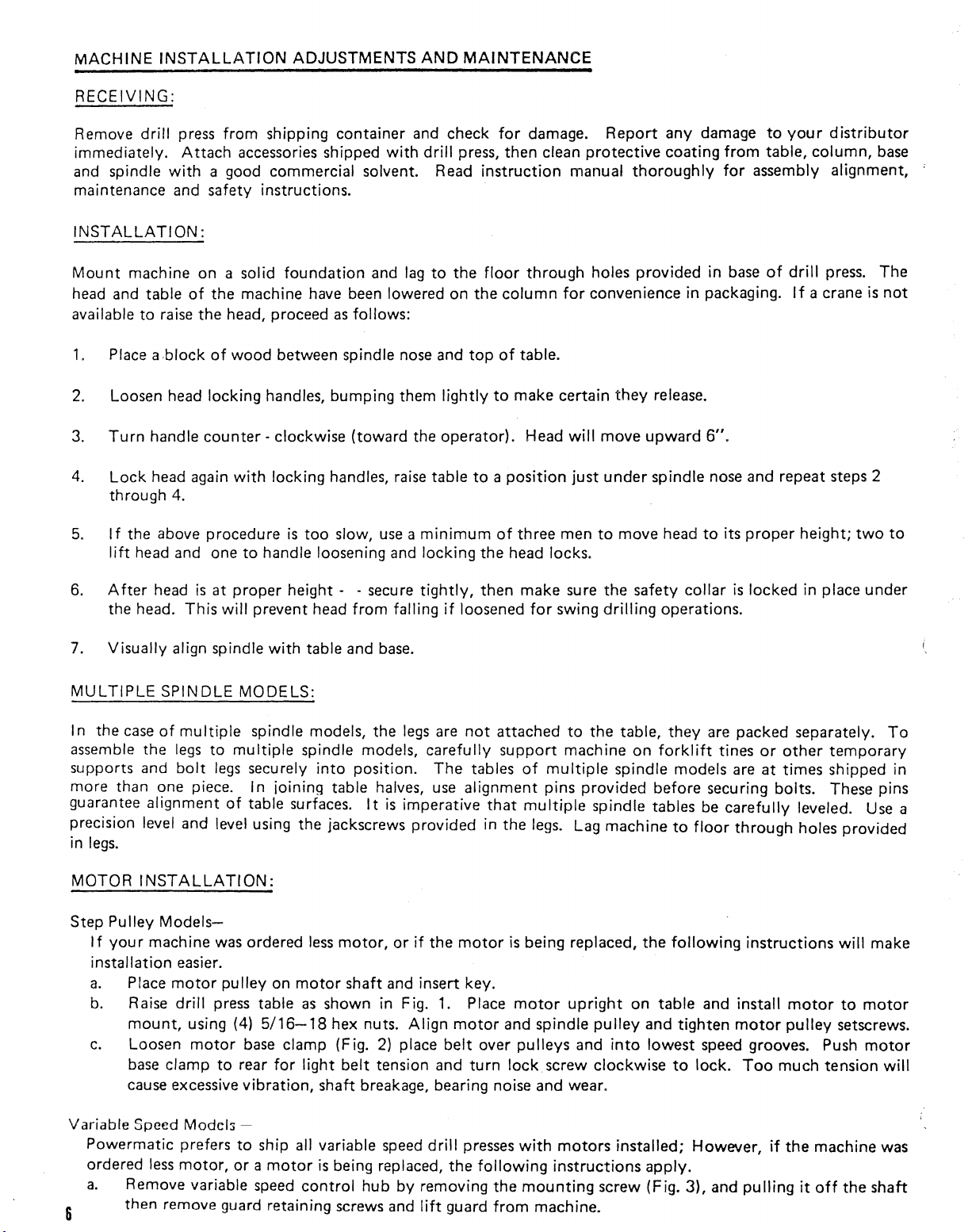
Place
motor
Raise
drill
mount,
Loosen
base
cause excessive
using (4)
motor
clamp
MODELS:
to
multiple
legs
securely
In
of
table surfaces.
pulley
press table
base
to
rear
vibration,
with
table and
spindle models, the
spindle models,
ioining
less
on
motor
as
5/16-18
clamp (Fig.
for
light
base.
legs
are
not
attached
carefully
into
position.
table halves,
It
jackscrews
motor,
shaft and insert
shown in Fig.
hex nuts.
2)
belt
tension and
shaft breakage, bearing noise and wear.
The
use
is
imperative
provided
or
if
the
Align
place
1.
belt
support
tables
alignment
that
in
the
motor
key.
Place
motor
and spindle
over
turn
is
motor
pulleys
lock, screw
to
the
machine
of
multiple
pins
provided
mu~tiple
legs.
Lag machine
being replaced,
upright
and
table,
spindle models are
spindle tables be
pulley
into
clockwise
they
are packed separately.
on
forklift
before securing bolts. These pins
to
floor
the
following
on
table
and install
and
tighten
lowest
speed grooves. Push
to
lock.
tines
or
at
carefully
through
instructions
motor
Too
other
temporary
times
shipped in
leveled. Use a
holes provided
will make
motor
pulley
much
to
setscrews.
tension
To
motor
motor
will
Variable
Powermatic
ordered
a.
6
Speed
Remove variable
then
less
remove
Models
prefers
motor,
or a motor
guard
-
to
ship all variable speed
is
being replaced,
speed
control
retaining
hub
screws
by
and
drill
presses
the
following
removing
lift
guard
with
the
mounting
from
motors
instructions
machine.
installed; However,
apply.
screw (Fig. 3), and
if
pulling
the
machine was
it
off
the
shaft
Page 7
BELT
..
)_._~~~_~
&-----f--,~
~
F"--M0 TOR
SHEAVE
-18
HEX
NUT(4
REao)
MOWR
sa
MOTOR
H~DC7
-;
FIGURE
INSTALLATION
VLOCK
/
[BELT
1
SCREW
SPACER
USED
ON
LENGTH
MOTOR
MAY
BE
DEPENDING
OF
C
'----------'
..
..
)c:=
(' @
BELT
o
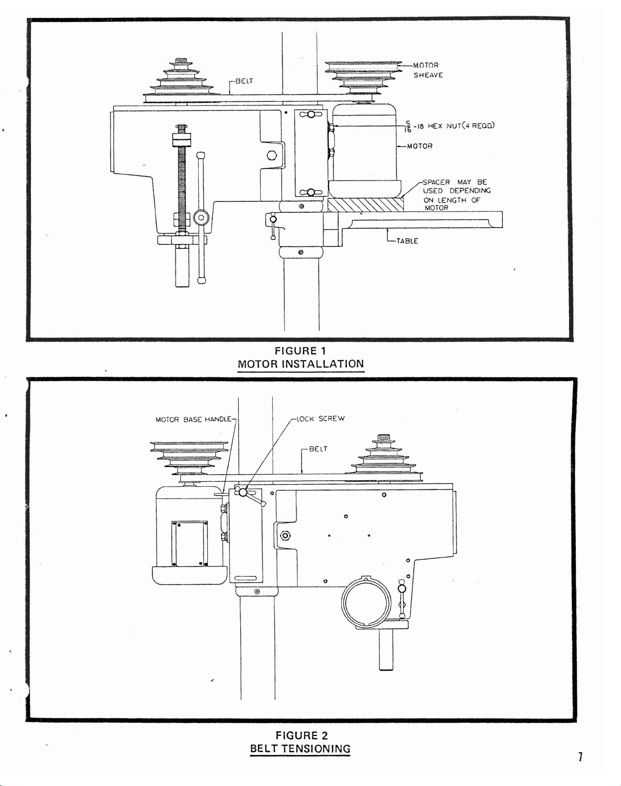
FIGURE
2
TENSIONING
o
o
o
-
7
Page 8
---""_.-...
b. Raise
c.
d. Before replacing guard -
drill
press table and
motor
to
motor
mount,
Place variable speed
between halves and
side
of
the pu lIey flange.
belt
shouId
pulley
be
and move
in a
on
lock
using (4)
motor
pulling
pulley
outward
temporarily
horizontal
shaft
until
in
position
5/16-18
on
motor
on belt. Insert
plane. If
belt
is
speed range.)
e.
Remove handle - - replace guard, then
NOTE:
CHANGING
Speed changes
clamp
When speed choice
(F
The
top
SPEEDS:
ig.
2)
above operations are easier
of
column)
on
step
and pu
is
made, move handle
pulley
II
handle
since
it
is
models are
toward
control
easier
operator.
to
Speed changes on variable speed models are
to
variable
If
spindle speed does
ometer
drive
drive
and adjust
(see
Fig.
mechanism
by
4)
clockwise
will
not
appear
unlocking
to
decrease speed and
result
the
if
speed
to
match the dial speed
setscrews in
(Fig. 1). Place
hex nuts.
shaft (spring
key
up);
in
replace variable speed
belt
is
cocked
at
level. Secure setscrew.
hub.
Machine
to
to
remove
to
be made
rear
to
perform
Belt
for
be made
is
adjusted
the
with
the
belt
with
is
now
proper
ONLY
on
upper
head raised
guard
the
free
tension and
while
variable speed
sheave
counterclockwise
motor
open
on
pulley
keyway,
control
an
angle,
(See
section on changing speeds
is
now
ready
with
machine
to
move
WHILE
machine
half
and
to
increase speed.
table in
by
then
tighten
hub
(Fig. 4).
shut
off
for
to
its
maximum
this
position.
not
running·
to
any
lock
the
MACHINE
is
not
unit
- - check speed
turning
upright
position
and attach
placing variable speed
screws in the
Turn
machine
the
motor,
bottom
on.
loosen
for
operation.
of
the
motor
IS
height
. loosen
5 speeds available.
base.
RUNNING.
(flush
motor
running.
with
the
top
nut
on the spline
belt
The
motor
setting
with
base
Damage
a tach-
~-
To
set speeds, adjust cam
outside
of
The
A
fter
a tab
INSTALLI
a.
b.
c.
diameter
the belt.
upper
If
sheave on the spline
adjustment
of
the
lockwasher
NG
Wipe
off
sure
no
foreign particles are
Apply a light
collar
rotating
on
and
When removal
there
CHUCK:
the
to
hand and using
tinued
chuck
LL
QUI
Lateral
pensate
a.
Be
b.
Squeeze
rotation
off
as
ADJUSTMENT:
play
or
bellmouthing
for
wear between the qu
sure
quill
slotted
compensate
of
spindle sheave.
is a minimum
lock
the
into
No.
33
spindle taper and tapered
film
of
the
threads at end
tighten
of
the
the
chuck
of
the
damage
lock
could
handle (Fig. 6)
head casting
for
wear
but
to
minimum
driver
setscrews
the
nut
oil
on
the
chuck
chuck
is
RPM, adjust
Move
motor
of
slack,
has
two
bring
the
to
lock
left
on these surfaces
spindle
of
spindle.
collar
with
required - -
key handle, loosen
collar
will
force
result
to
chuck, spindle nose and spindle bearings.
can develop between
ill
and head, proceed
is
loose.
together
do
not
restrict
the
setscrews
lock
its
taper
drill
the
chuck
slightly
free
by
means
back
until
motor
and
which
nut
down
position.
socket
which
and place
Hold
spindle
chuck
disconnect
chuck
motion
collar
off
tapered spindle.
the
quill
as
follows:
by
tightening
down
of
nut
on
the
belt
belt
system are
must
against
in
chuck
cou Id
chuck
has
minimum
be
body
prevent
on end
pulley
properly
unlocked
the
hub
(Fig. 5)
with
spline
proper
of
one hand
of
play. Pull
for
of
the
with
spindle
driver
adjusted in
seating
key.
power
by
source.
turning
Hold
counter
NEVER
top
- clockwise (Fig. 5). Conattempt
and head casting bands due
bolt
(A).
Apply
or
return.
to
flush
out
the
sheave
upper
sheave and bend
a clean
of
the
(F
ig.
5). Screw
to
keep spindle
spindle
just
pulley
to
drive
to
wear.
enough pressure
belt
on
one side
this
position.
to
be moved.
cloth.
two
with
or
wedge
To
with
Make
parts.
chuck
from
one
com·
to
QUI
LL
Spring
ment
tension
should be
spindle
ing
quill
entire
housing assembly clockwise the
position.
RETURN
drilling
spring housing (B), DO
(NOTE:
SPRING
for
return
attempted
or
tapping head
The
ADJUSTMENT:
of
spindle,
after
unless absolutely necessary.
is
used.
NOT
flat
of
the spring housing
aof the spring housing.) Reset lockscrew
hole
If
adjustment
allow
number
(A),
drilling,
the
housing
of
turns
pilot
make sure
has been pre-set
Adjustment
is
necessary, loosen
to
turn
in
your
necessary
is
lined
up
with
point
of
screw mates
will
to
at
the
factory.
probably
lockscrew
hand,
cause
the
or
the
spring loading
to
No
be
required
(A) (Fig. 7)
spring
quill
flat
will
to
on the housing
further
if a multiple
unwind.
return
hole
on
while
to
the
journal.
adjust-
holdTurn
its
up
body
Page 9

VIS
FIGURE 3
GUARD
REMOVAL
FIGURE 4
VIS SPEED ADJUSTMENT
v.S._,
:~"-lTRO~
"'!UB
I
SPINDLE
SPINDLE
THREADS--~~:Jt-
CHUCK
FIGURE 5
KEY CHUCK
...
TiGHTEN
lOOSEN
KEY
INSTALLATION
~
CHUCK
CHUCK
COllAR
QUILL
LOCK
HANDLE
QUILL
0
r-==
............,,:
R
~
FIT
@
[j]
t--
(A)
FIGURE 6
UP
ADJUSTMENT
!.
p
@
L.-
'-'-
r!
0
-
~
h
u......u
9
Page 10
"'-
..
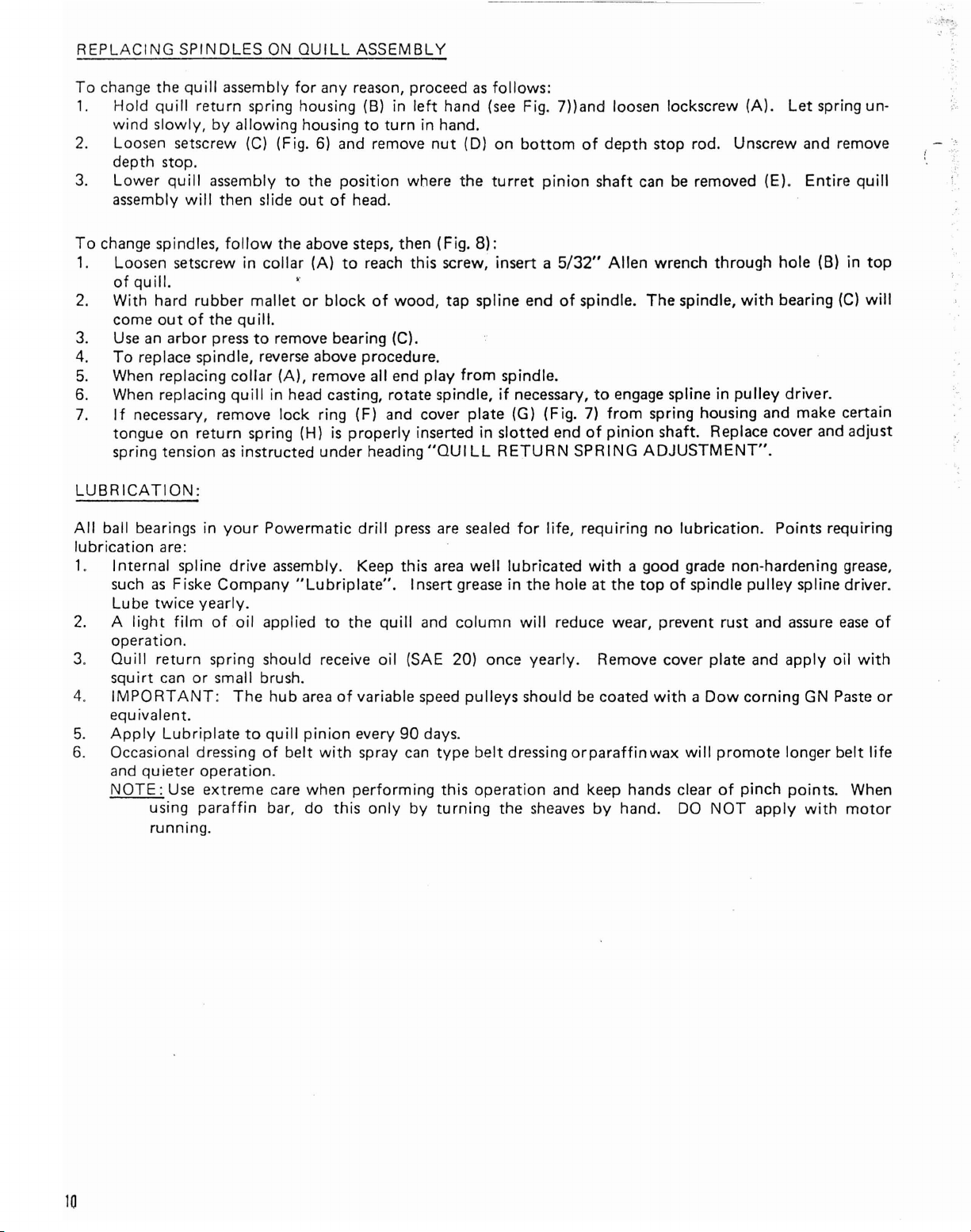
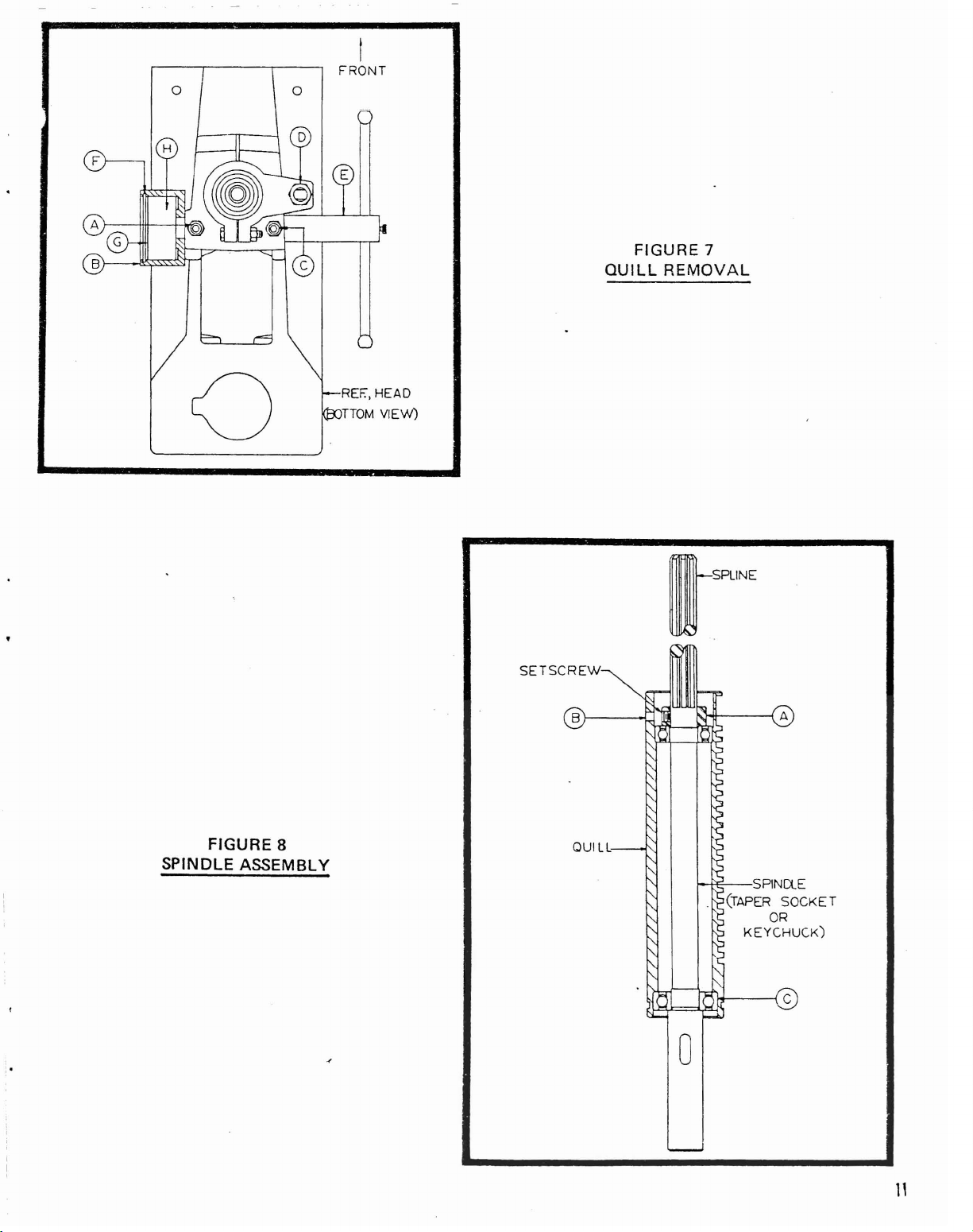
REPLACING
To
change the
1.
Hold
wind
2.
Loosen setscrew (C) (Fig.
SPINDLES
quill
quill
return
slowly,
by
depth stop.
3.
Lower
assembly
To
change spindles,
1.
Loosen setscrew in
of
2.
With
come
3.
Use
4.
To
5.
When replacing
6.
When replacing
7.
If
tongue on
spring tension
quill
assembly
will
then slide
quill.
hard
rubber
out
of
the
an
arbor
press
replace spindle, reverse above procedure.
necessary, remove
return
as
LUBRICATION:
ON
assembly
QUILL
for
ASSEMBLY
any reason, proceed
spring housing (B) in
allowing
follow
mallet
housing
to
the
out
to
6)
and remove
position
of
head.
turn
the above steps, then (Fig.
collar
or
(A)
block
to
reach this screw, insert a 5/32"
of
quill.
to
remove bearing (C).
collar
(A),
remove all end play
quill
in head casting, rotate spindle,
lock
ring (F) and cover plate (G) (Fig.
spring (H)
instructed
is
properly
under
heading
left
in hand.
nut
where
wood,
inserted in
"QUI
as
follows:
hand
(see
Fig. 7))and loosen lockscrew
(OJ
on
bottom
the
turret
8):
tap spline end
from
spindle.
if
necessary,
slotted
LL
RETURN
pinion
of
end
SPRING
of
depth
shaft
can
Allen
spindle.
to
7)
of
The
engage spline in
from
spring housing and make certain
pinion
ADJUSTMENT".
(A).
Let
spring un-
stop rod. Unscrew and remove
be
removed (E).
wrench
spindle,
through
with
pulley
Entire
hole (B) in
bearing
(C)
driver.
quill
top
will
shaft. Replace cover and adjust
;
"
All
ball bearings in
lubrication
1.
such
2.
A
are:
Internal spline
as
Fiske
Lube
twice
light
operation.
3.
Quill
return
squirt
4.
IMPORTANT:
can
equivalent.
5.
Apply
6.
Occasional dressing
Lubriplate
and qu ieter
NOTE:
Use
using
running.
your
Powermatic
drive
assembly. Keep this area
Company
yearly.
film
of
oil
applied
spring should receive
or
small brush.
The
hub
to
quill
of
belt
operation.
extreme
paraffin
care when
bar, do
drill
"Lubriplate".
to
the
quill
oil
area
of
variable
pinion
with
every
spray
performing
this
only
press
are
sealed
Insert grease in
and
column
well
for
life, requiring
lubricated
the
hole at
will
reduce wear, prevent rust and assure
no
lubrication.
with
a good grade non-hardening
the
top
of
spindle
(SAE 20) once yearly. Remove cover plate and
speed
90
can
by
days.
type
this
turning
pulleys
belt
operation
should be coated
dressing
orparaffinwax
and keep hands clear
the
sheaves
by
hand. DO
with a Dow
will
promote
of
NOT
corning
pinch
Points requiring
pulley
spline driver.
apply
GN Paste
longer
points. When
apply
with
grease,
ease
oil
with
belt
motor
of
or
life
10
Page 11
o
o
o
I
FRONT
REF.,
HEAD
nOM
VIEW)
FIGURE 7
QUILL
REMOVAL
FIGURE 8
SPINDLE ASSEMBLY
SETSCREW
o-SRINE
1--+1E'---S
PIN
(TAPER
OR
KEYCHU(K)
Ct.
E
SOCKET
o
Page 12

~RTISE
ATTACHMENT
INSTALLATION
IMPORTANT NOTE: Mortise attachments cannot be installed'on Morse
To
mount
bolt
locknut
Insert proper size hollow chisel (with discharge hole
between shoulder on
head
mortise attachment, remove quill
at rear
bott
(B).
(D).
of
quill. Replace
top
Insert
drill bit into chisel allowing shank
yoke
of
chisel and
yoke
(Fig.
9)
by removing locknut (8) and loosening yoke clamp
with chisel housing (C). Insert depth stop rod into housing and replace
to
left if possible) into chisel housing. Insert a dime
bottom
of chisel housing. Lock chisel
to
extend as far as possible into chuck jaws. Apply
Taper
in
Spindle Models
..
place temporarily with square
pressure against bit end with a wood block and while holding, pressure tighten chuck jaws securely. Remove
dime and move chisel up against chisel housing.
as
tables
pictured
in
Fig. 9.
The
mortise attachment
lockscrew
is
now ready
(0)
tightly. Affix fence assembly
to
use. Use
short
pecking strokes on
to
tilting
all
Set
mortise operations.
If
chisel end begins
Pressures exerted during mortise operation will sometimes force drill
clearance gap. A loud squeal
to
turn
blue, check chisel for sharpness and clearance between end
bit
deeper into chuck jaws, reducing
is
usually an indication
of
insufficient clearance.
of
drill
bit
and chisel.
12
GUARO ASSY.
(2250091)
GUARQ ASSY.
(2250092)
MORTISE
(nOOR
MTGJ
(WITH
eAsE)
FIGURE 9
ATTACHMENT
rOOT
ASSY
(2192003)
INSTALLATION
rEED
Page 13

TROUBLE
SHOOTING
HINTS
TROUBLE
Exce~~ivg
I
Motor
Noisy Operation
Drill
Up
ori
II
Excessive
or
Work
Loose
Vibration
Stalls
or
Tool
or
Burns"
Leads 0
Drill
Wobble
or Fixtu
or
Spins.
Heats
ff
Work
Runout
re
Comes
'I.
2.
3.
4.
1.
-,
2.
3. V/S
4.
5. Bad
1.
2.
3.
4.
1.
2.
3.
4.
5.
6.
1.
2.
3.
4.
1.
2.
3.
1.
PROBABLE
I
mproper
Uneven
Motor
belt
or
belt
spindle
CAUSE
tension.
wear (hard spots).
pulley
out-of-
-l-""'"
REMEDY
Adjust
1.
Replace belt.
2.
Balance
3.
belt
or
tension.
replace
balance.
Replace
Bad
motor.
Over feeding.
Dull
drilL
belt
Motor
riding on
not
building
inner
up
cone.
to
running
speed.
motor.
Excessive
Improper quill
Noisy
Noisy
Excessive speed. 1. Reduce speed.
Chips
Dull
Feed rate
Rotation
Failure
coolant
No
Cutting
Quill
Bearing play.
Bent
Bearing
Drill
chucks.
Failure
work
vibration.
spline.
motor.
not
clearing.
tool.
too
of
drill
to
use
(on steel).
drill
spot.
lips on
loose in head.
drilt.
play.
not
seated
to
clamp
holding
adjustment.
slow.
incorrect.
cutting
drill
device
oil
off
properly
workpiece
to
or
center.
in
or
table.
4.
Reduce feed rate.
1.
Sharpen
2.
3. Re-adjust V/S belt.
4.
Replace
fuses in all three
.
motors
5. Replace
Check remedy
1.
vibration.
Adjust
2.
quill
Lubricate
3.
Check
4.
motor
Use
2.
3. Sharpen
Increase feed enough
4.
Reverse
5.
wiring
J
Use
6.
Center
1.
Regrind
2.
Tighten
3.
Check bearings and reseat
4.
necessary.
Replace
1.
straighten.
Replace
2.
Loosen, reseat and
3.
Clamp
1.
device
motor.
drill
or
repair
and replace
motor.
quill
(refer
adjustment).
spline.
motor
fan.
pecking
cutting
operation
tool
motor
diagram).
oil
punch
drill.
quill
drill.
or
reseat bearings.
workpiece
to
table
"
,--
problem
and keep sharp.
motor.
regs
on three phase
if
under
to
bearings
or
replace.
rotation
or
coolant
or
center
(refer
to
Do
not
tighten
or
su
rface.
pulley.
Check
necessary.
excessive
paragraph on
or
for
to
clear
to
clear chips.
(refer
on steel.
drill
quill
or
attempt
chuck.
work
holding
--,
loose
ch
ips.
to
motor
workpiece.
adjustment).
replace
if
to
f
I
13
Page 14

:I:
m:I:
»m
0»
»0
en»
sm
~~
-<r-
IOJ
coS:
-<
"
...l
--
C/) .....
-OC/)
:0."
-:0
2-
G)Z
-iC)
m-<
-am
:t>"
cnJ:
:DC")
Oc
nO
-i
m
"'"
'\
12-/\
SET
LIEU
IN
(49)COMPRISE
USED
IS
9COJIS. RAPID
~6)THRU
NO.
STOP AND
ASSY.
ITEMS
I.
NOTES'
(12)
ITEM
OF
USED
COMPRISE
IS
(54)
ANLJ
THRU
9100016, TURRE T
ASSY.
(~U)
NO.
ITEMS
HANDLE
ASSY.
2.
(6\("/)
0)
(f
ANf)
LIEU or ITEMS
IN
(8)
-0
---0)
,..}
'~
~
®~
~--=--@>
-G7
I
-
.@
_-@
I
I
,--@
~-@
't"
.
"
~,
~
~.
~.
,,~
r,.
.-
~"',
~//
ij,
G)
~
~
@-
'-
"-
~-
~L'~«~
~8)
--.,----,
r;0
.........
.~
":
..
;;._~_
I ®
~O
~O;-~_
~
Qyr-----
I
I
I .
I@__ _
t
I
i
I
j®--.-
'''
~
m"
~
,
/
..
eJ
5~
@-
-~
~o~---
I
'''1
"-,
._.
1
,
--~~ct=::Ji\
-
"Jk~
__
I@
if£)
,
----@
----
..
0
-
®
:
~-J
~~
'.
'
~
..".-
~
I, I
ONLY
SOCKET
ASSY.
(2640018)
TAPER
QUILL
ASSY.ONLY-·
(2640017)
~EYCHU(K
QUilL
Page 15

NO.
PART
NO.
HEAD
ASSEMBl
DESCRIPTION
Y
CTY.
".------------------------,
NO.
PART
HEAD
NO.
ASSEMBLY
DESCRIPTION
QTY.
f
,
':l1440Q3
1
6670006
3144006
2
3
6060014
4
3737021
6804003
5
2240071
3406045
6
7 6714019
I 8
9
10
6430024
3586025
3268053
2670014
11
3526093
12 3526094
13
6626035
14
3670102
3528005
15
2695009
16 3268002
17
3695010
18 3406016
2640017
2640018
19 6715016
20 3096244
21
6060165
3640016
22
23
6060009
24
2749037
3749105
25
6118005
26
27
2440013
3277028
28
3448014
29
30
6861513
31
3526039
32
3661016
33
3104010
34
6715116
35
6813026
36
3298288
37
6716040
38
6518001
39
6718038
40
6804004
41
6715039
42
6515001
43
6714090
44
3936013
45
3528005
9100015
46
6515006
47
6715010
48
3055104
3689070
49
9100016
2268006
3406206
50
3670025
51
52 6715013
DRIVE
SPLINE
5)
RETAINING
INTERNAL
BEARING
BEARING
"0"
RING
PINION
GEAR
THRU
10)
HANDLE
SOC
SHEAR·LOC
QUILL
HANDLE
DEPTH
THRU
GRADUATED
PLAIN
SPRING
DEPTH
LOCK
LOCK
THRU
HANDLE
LOCK
HANDLE
KEYCHUCK
19
TAPER
19
CUP
COLLAR
BEARING
SLIDING
BEARING
SPINDLE
CHUCK
TAPER
TAPER
JACOBS
HEAD
MENT)
DRILL
HEAD
FLAT
NUT,
RETAINING
SPRING
HALF
-18
SPRING
SINGLE
HEX
HEX
HALF
-13
"0"
HEX
HEX
HALF
-20x
QUILL
LOCK
RAPID
49)
HEX
FLAT
STOP
LOCK
TURRET
THRU
HANDLE
PHENOLIC
TURRET
KNURLED
HD
OPERATING
ADJ
15)
DEPTH
ADJUST
NUT
seR
18)
seR
THRU
SOCKET
THRU
PT
SOC
ONL
SOCKET
SOCKET
SLEEVE
PRESS
SLEEVE
WASHER
1/2-13
DOG
x 1/2
HD
NUT,
DOG
x 1-1/4
RING
HD
NUT
DOG
1/2
YOKE
NUT
SET
(IN
LIEU
NUT,
PT
BLOCK
SCREW
54)
KNOB
CAP
PIN,
KNOB
24)
23, &
QUILL
ASSY,
CHUCK,
COVER
SPRING
seR
SCR,
SOC
HANDLE
ROD
5/16-18x3/8
ASSY,
RING
DRIVE
SPACER
ASSY,
seR
KNOB
ROD
ASSY,
DEPTH
STOP
3/16
ROD
ASSY.
QUILLASSY,
QUILL
25)
SET
SCR,
(1
Y)
SPINDLE
ON LY)
1/2"
LOCK
HEAD
LOCK
1/2"
RING
PT
SOC
HOUSING
3/8-16 x 2·1/2
1/2-13
PT
SOC
5/16-18
5/16-18
PT
SOC
STOP,
OF
STANDARD)
5/16-18
SET
(IN
LIEU
ASSY
(ITEMS
KNOB
CUP
PT
(lTEM5 1
(SHAFT)
(ITEMS
6
~.'4-20
x
5/8
PINION
(ITEMS
STOP
NUT
NUT
)(
5/8
(ITEMS
16
(ITEMS
ASSY,
5/16-18
SPRING
SET
SET
w/33
ASSY,
SCR,
SCR,
KEY·
(1
SPRING
MT
(WELD·
5/16
1/2
x 1-3/4 1
SET
SCR,
1/4
(ITEMS
46
THRU
SCR,
5/16-18
~
ASSY,
(ITEMS
OF
STANDARD)
50 &
51)
SOC
SET
SCR,
T~-cfRU
11
(ITEMS
x 5/16
x
1/2
50
1
- •
54 6420001 WOODRUF F
KE
Y
"1
2
1
2
1
1
2
1
1
1
1
1
1
1
1
1
i
1
1
1
2
1
1
1
1
1
1
1
1
I
1
1
1
1
1
1
1
I
1
1
1
2
2
1
1
1
1
1
1
1
1
1
3
1
!
1
1
15
Page 16

VARIABLE
SPEED
@
I
ASSEMBLY
'/F:'
'C,
~
'&
I
,"CO'"
t~
~'~
I I i
® ®
I I I I
®®
@
®
I
\
Page 17

VARIABLE
SPEED
ASSEMBL
Y
VARIABLE
SPEED
ASSEMBL
Y
--
NO.
PART
2404005
2298033
2305002
1
6626056
3406045
2
3268056
3
3301042 SPEED
4
6716123
5
3703013
6
32982"36
7
6516001
8
6716117
9
I
10
i
6715032
11
3673032
12
6095043
I 6515007
13
14
3936014
15
2076004
16 6670002
17
6813089
2719065
18 3096144
19
6623013
6060123
20
21
2719069
3719177
22
6765003
23
24 6864006
6549006
25
6714154
26
6861101
27
28 3062109
29 6077158
3387028
30
31
2042163
2250140
6714083
32
33
6458002
34
2250131
6710003
35
36 6860800
6510009
37
2388061
38
3119003
39
3119005
3330284
40
3312228
41
6747000
42
43
6861201
44
6715035
45
3277028
6716031
46
47
6861300
48 2719066
49
6515001
50
6861200
51
6861201
6470600
::>2
6470607
6470608
NO.
VIS
31
HOUSING
17)
SPEED
1
THRU
SPA
HANDLE
HANDLE
BUT
CAM
CAM
HEX
SLOTTED
3/8-16
HEX
VIS
BUSHING, .3125/.3115 10 x .4375/.4365
00
HEX
VIS
VIS
RETAINING
I
BELLVILLE
VIS
18
BEARING
DOWEL
FAFNIR
VIS
FIXED
CUP
(ONE
LOCK
LOCK
HEX
FLAT
ANGLE
VIS
FLAT
MOTOR
VIS
DESCRIPTION
KIT
ASSY,
)
ASSY,
HANDLE & HUB
4)
ING
PIN,
KNOB
HANDLE
HD
SCR,
SHAFT
HOUSING
NUT
3/8-16
HD
x
1-1/2
HD
SCA
ROLLER
x
3/8
JAM
NUT,
YOKE
CAM
ASSY
DRtVEN
THRU
25)
COLLAR
PIN
BEARING
SLIDING
FLANGE
PT SOC
NOT
SHOWN)
WASHER,
NUT,
HD
seR,
WASHER,
BRACKET
BELT
KEY,
MOUNT
GUARD
(ITEMS 1 THRU
(ITEMS 1 THRU
5/32 x 3/4
HUB
3/8-16
x 1 1
SET
CONE
5/16-18
5/16-18
RING
SPRING
SHEAVE
5/16
SHEAVE
SET
N-06
1/4-20
3/16 x 1/4 x 3·5/16
ASSY
ASSY
x 1
SHEAVE
SCR,
5/16-24 x 1/2
W-06
x
1/4
BASE
(ITEMS
37)
BUT
HD
SCA
1/4-20
RUBBER
GUARD
TRUSS
FLAT
SPEED
ViS
42)
IDENTiFICATION
NOJ
IDENTIFICATION
MATIC)
SAFETY
SERIAL
DRIVE
SHOWN)
FLAT
HEX
HEAD
HEX
LOCK
MOTOR
HEX
LOCK
FLAT
ELEC
RPM
ELEC
RPM
ELEC
RPM,
MOLDING
ASSY
HD
SCA,
WASHER,
NUT
PLATE
KIT,
DECAL
PLATE
SCA,
WASHER
HD
CAP
HD
SCR
WASHER
SHEAVE
NUT,
5/16-18
WASHER
WASHER,
MOTOR,
115/230V
MOTOR,
20QV
56FR
MOTOR, 3/4
230/460V,
NO.4
SCR
x
(WELDMENT)
10-24
NO.
10
(ITEMS
DECAL
DECAL
(NOT
(NOT
SHOWN)
x 3/16
5/16
5/16-18
3/8-16
x 1 2
3/8
ASSY
5/16
5/16
3/4
HP,
56
FR
3/4
HP, 3 PH,
TEFC
HP,
56
FR,
ASSY,
(ITEMS
PT
seR,
x 1
(ITEMS
3/8
ASSY
32
THRU
1/2
x
1/2
38
THRU
(MODEL
(POWER-
SHOWN)
(NOT
x
3/4
1 PH,
1200
TEFC
1200
3 PH, 1200
TEFC
QTY.
1
2
2
1
1
1
2
2
1
1
1
1
1
1
2
1
1
2
1
1
1
2
1
1
2
2
I 2
1
1
1
2
2Ft.
1
2
2
2
1
2
1
1
2
4
4
1
2
1
4
4
4
NO.
PART
6470700
6470702
6470707
6470712
6470602
NO.
DESCRIPTION
ELEC
MOTOR,
RPM,
115/230V,
ELEC MOTOR,
RPM
575V
ElEC
RPM
ElEC
56
MOTOR,
230/460V 56 FR
MOTOR,
RPM, 200V, 56
ELEC MOTOR,
RPM,
230/460V,
REVERSING
3/4
HP, 1 PH.
56
FA,
3/4
FR
3/4
TEFC
HP, 3 PH,
TEFC
HP, 3 PH,
TE
3/4
HP,
FR,
3/4
3 PH, 1800
TEFC
HP, 3 PH, 1200
56
FR,
Fe
ODP,
1800
1800
lBOO
HIGH
I
I
I
I
I
QTY.
I
I
I
17
Page 18

STEPCONE A
\
SSEMBLY
I
e
18
Page 19

'\1.
}/
J~
........,.,...-,..
NO.
1
2
3
4
5
6
7
8
9
10
11
12
13
14
15
16
17
18
19
20
21
22
23
24
25
26
27
28
29
30
31
32
33
34
35
36
37
38
39
40
41
PART
NO.
2381004
6077018
3062109
6861101
6714154
6330002
2042164
6715014
3718031
3387028
2250141
6710034
6122038
·6510001
3755258
2250133
2250132
6458002
6714083
6710003
6860800
6510009
2268025
3268002
3448032
3406016
6515001
6715143
2717003
3718032
6715014
"2388062
3119004
3119005
3330284
3312228
6747000
6861201
6336010
6715035
6861201
3277028
6861201
6861200
6515001
6470600
6470607
6470608
6470700
6470702
6470707
6470712
64-70602
STEPCONE
STEPCONE
1
THRU
VEE
ANGLE
FLAT
HEX
VINYL
STEPCONE
CUP
STEPCONE
FLAT KEY
STEPCONE
10THAU
RD
WECKESSER
HEX
SPRING
DOOR
GUARD
RUBBER
BUT
TRUSS
FLAT
SPEED
STEPCONE
ASSY
LOCKSCREW
STEPCON E
HANDLE
HEX
FLAT
STEPCONE
(ITEMS
STEPCONE
CUP PT SOC
STEPCON E
THAU
IDENTIFICATION
IDENTIFICATION
SAFETY
SERIAL
DRIVE
SHOWN)
FLAT
RUBBER
HEX
FLAT
HEAD
FLATE
LOCK
HEX
ELEC
115/230V
ELEC
RPM,
ELEC
RPM
ELEC
RPM
ELEC
RPM
ELEC
RPM,
ELEC
RPM
ELEC
RPM,
REVERSING
9)
BELT
BRACKET
WASHER,
HO
SCA
GRIP,
P.T
SOC
HO SCA,
NUT
GUARD
ASSY
MOLDING
HO
SCA
HD
WASHER
NUT
(ITEMS
NUT
PT
SET
26
32)
DECAL
PLATE
SCR,
WASHER
GROMMET
HD
SCA
WASHER
WASHER
WASHER
NUT
MOTOR,
MOTOR,
200V,
MOTOR,
230/460V
MOTOR,
115/230V
MOTOR,
575V
MOTOR,
230/460V
MOTOR,
200V
MOTOR,
230/460V,
ASSEMBLY
DESCRIPTIONS
SHEAVE
MOTOR
seT
SHEAVE
3/16 x 1/4
GUARD
20)
10-24 x 1/2
10-24
seR
BASE
MOTOR
LOCKSCREW
5/16-18
MOTOR
& 27)
SHEAVE
SET
PLATE
No.4
5/16-18
56
56
56
56
KIT,
1/4
1/4-20 x 3/8
.090
x 1 x 3
BASE
seR,
5/16-18 x 1/2
x 3
ASSY
CLAMP
1/4-20 x 1/2
3/16-H-FR
ASSY
(WELDMENT)
(WELDMENT)
10-24 x 1/2
No.10
LOCK
21
THAU
HANDLE
MOUNTLOCK
seR
5/16-18
SHEAVE
SCR
5/16-18 x 1/2
KIT,
DECAL
DECAL
(NOT
SHOWN)
(NOT
SHOWN)
x
3/16
5/16
5/16-18 x 3/4
5/16
5/16
5/16
*HP, 1
Fr.
3/4
FR.,
3/4
3/4
3/4
FR
3/4
3/4
FR
3/4
TEFC
HP, 3 PH,
FEFC
HP, 3 PH,
56FR.
HP, 1 PH,
56
FR.
HP, 3 PH,
TEFC
HP, 3 PH,
56
FR
HP, 3 PH,
TEFC
HP, 3
56
FA,
PH,
(ITEMS
ASSY
..
5/16
(ITEMS
HANDLE
25)
KNOB
x 1-1/4
(ITEMS
(NOT
1200
1200
1200
TEFC
1800
TEFC
1800
1800
TEFC
1800
PH,
1200
OOP,
HIGH
ASSY
28
RPM
~r
..."'"
p~
QTY.
,
2
2
2
1
1
1
1
,
4
2
4
1
1
1
2Ft.
2
2
2
2
1
1
1
1
1
1
1
1
2
1
1
2
1
2
2
2
1
4
4
4
I
19
Page 20

PRODUCTION
@
@
TABLE
&-~~~S·--E-
-
ASSEMBLY
9-----
~
D'
_
@~
--
.-.
4.
@J
O'~t
I
,~
~
@
...
I
_.
1
---
20
~._-
Page 21

PRODUCTION
NO.
PART
NO.
•
1
,~
,
t
i
:.~
2797033
2797.132
2268013
6624006
1
2 3268201
3
3268005
4
6670008
6626038
5
6626040
6
3701001
7
3838009
8
2729004
9
6064001
10
11
3237332
6716099
12
13
3237333
14 3743011 SPACER 2
3710007
15
16
6638004
3797303
17
2695019
3268002
18
19
3695014
3406016
20
2645003
6626033
21
3650005
22
6715118
23
TA66[; &
OEseR
PRODUCTION
1
THRU
PRODUCTION
(ITEMS 1 THRU
TABLE
ASSY
FLAT
NYLON
TABLE
RETAINING
SHOWN)
SPRING
SPRING
ELEVATING
BEVEL
HEAD
THRUST
WORM
HALF
x
SPUR
GEAR
PIPE
PRODUCTION
PRODUCTION
ASSY
HANDLE
LOCK
KNOB
TABLE
21
RACK
3/16
TABLE
24"
HALF
30)
RAISING
(ITMES 1 THRU
HD
PIN.
MACHINE
ELEVATING
RING
PIN,
1/4
PIN.
1/4 x 1·1/4
HANDLE
WASHER
RAISING
BEARING
GEAR
DOG PT SOC SET SCR.
5/8
GEAR
SHAFT
PLUG
1/2-14
(ITEMS
SCR
RAISING
THRU
27)
MOUNTING
x 2
ELEVATING
LONG
DOG PT SOC SET SCR.
BASE
IPTION
TABLE
TABLE
17)
PINION
3"
LONG
HANDLE
(ONE
xl
SLEEVE
TABLE
TABLE
18
THRU
RACK
SPRING
ASSEMBLY
ASSY.
(ITEMS
SUB
ASSY.
HANDLE
3)
HANDLE
NOT
SHAFT
ASSY 1
3/8-16
LOCK
SCR
20)
ASSY,
(ITEMS
PIN
GEAR
RACK
5/16
OTY.
1
1
1
3
1
.
1
1
1
1
1
1
1
1
1
1
1
1
1
1
1
2
-18x3/4
24
6515001
25
3078026
6054002
26
27
3096042
3598023
28
6718055
29
30
6716114
31
3042121 1
32
6718056
3098209
33
34
3598023
"
35
6718055
3096008
36
37
9100014
HEX
NUT.
THRUST
STEEL
THRUST
BRASSPROTECTORSETSCR
PLUG.
CUP PT SOC
HD
WINYLOK
DRILL
CUPPT SOC
DRILL
BRASSPROTECTORSETSCRPLUG
BEARING
BALL
BEARING
7/16 x 3/16
HEX
SCR.
PRESS
PRESS
5/16-18
COLLAR
3/8"
DIA.
COLLAR
SET
SCR.
3/8-16 x 2·3/4
INSERT
8ASE
SET
SCR.
COLUMN
CAP 1
1/2-13
x 1/2 1
1/2-13 x 3/4
7/16x3/16
CUP PT SOC
SAFETY
FINISHED
SET
COLLAR
BASE IN
SCR
LIEU
1/2-13 x 1/2
OF
CAST
2
30
1
1
2
1
1
2
2
1
1
'11
Page 22

@
@
c
.:>i"l
NDL
E
TABLE
AND
LEG ASSEMBLY
I
1
g
,
,
l
,
:
~
I
..
I
-,
"
Page 23

".
•
,
..
~
,
~
~
I
MULT SPINDLE
PART
NO.
3063075
1
6517001
2
3098208
3
6717020
4
6717018
5
6
3797016
7
3797017
3797039
8
9
379706B
10
3797038
11
3797067
12
3797037
13
3797066
14
2797122
15
2797124
16
2797014
17
2797125
18
2797015
19
2797126
20
2423007
21
2423008
NO.
COLUMN
1
SPINDLE
2
SPINDLE
3SPINDLE
4
SPINDLE
SPINDLE
5
SPINDLE
6
8
SPINDLE
HEX
1
SPINDLE
2
SPINDLE
3
SPINDLE
4
SPINDLE
SPINDLE
5
6
SPINDLE
8
SPINDLE
BENCH
1
SPINDLE
SPINDLE
2
3
SPINDLE
4
SPINDLE
SPINDLE
5
SPINDLE
6
8
SPINDLE
HEX
1
SPINDLE
2
SPINDLE
3
SPINDLE
4
SPINDLE
SPINDLE
5
SPINDLE
6
8
SPINDLE
HEX
1
SPINDLE
2
SPINDLE
3
SPINDLE
4
SPINDLE
5
SPINDLE
6
SPINDLE
8
SPINDLE
ONE
ONE
TWO
TWO
THREE
THREE
FOUR
FOUR
FIVE
T·SLOTS
FIVE
T-SLOTS
SIX
T·SLOTS
SIX
T-SLOTS
EIGHT
T·SLOTS
EIGHT
T·SLOTS
TABLE
1
SPINDLE
SPINDLE
2
3
SPINDLE
SPINDLE
4
5
SPINDLE
6
SPINDLE
8
SPINDLE
TAB
5
SPINDLE
6
SPINDLE
8
SPINDLE
I
TABLE & LEG
DESCR
MOUNTING
NUT.
7/16-14
MODEL
HD
HD
SPINDLE
SPINDLE
SPINDLE
SPINDLE
SPINDLE
SPINDLE
SPINDLE
SPINDLE
SPINDLE
SPINDLE
SPINDLE
SPINDLE
SPINDLE
SPINDLE
END
LE
MI
CAP
CAP
DO
COLUMN
SCR,
SCR,
TABLE
TABLE
TABLE
TABLE
TABLE
TABLE
TABLE
TABLE
TABLE
TABLE
LEG
LE
TABLE
TABLE
TABLE
TABLE
ASSY
LEG
ASSY
IPTlON
BRACKET
7/16-14 x 2-1/2
7/16-14 x 1-1/2
W/O
T-SLOTS
WI
T-SLOTS
W/O
T-SLOTS
WI
T-SLOTS
W/O
T-SLOTS
WI
T-SLOTS
WIO
T-SLOTS
WI
T-SLOTS
ASSY
W/O
ASSY
WI
ASSY
W/O
ASSYWI
ASSY
W/O
ASSY
Wi
~
ASSY
OTY.
1
2
3
4
5
6
8
1
2
3
4
5
6
8
1
2
3
4
5
6
8
1
2
3
4
5
6
8
4
8
12
16
20
24
32
1
1
1
1
1
1
1
1
1
1
1
1
1
1
2
2
2
2
2
2
2
1
1
2
NO.
22
23
24
MU LT
PART
6717015
3694005
.
6638004
NO.
SP
IN DLET
HEX
1
SPINDLE
2SPINDLE
SPINDLE
3
SPINDLE
4
5SPINDLE
6
SPINDLE
8
SPINDLE
TABLE
SPINDLE
1
SPINDLE
2
3
SPINDLE
4
SPINDLE
5SPINDLE
SPINDLE
6
SPINDLE
8
sa
1
SPINDLE
2
SPINDLE
SPINDLE
3
SPINDLE
4
5
SPINDLE
6
SPINDLE
8SPINDLE
HD
HD
CAP
LEG
PIPE
A BLE &
DESCRITPION
seR,
7/16-14 x 1-1/4
LEVELING
PLUG,
1/2-14
LEG
SCR
ASS Y
! orr
8
8
8
8
12
1:2
16
4
4
4
4
6
6
8
1
1
1
1
1
1
1
23
Page 24

24
NO.
1
2
3
4
5
6
7
8
9
10
11
12
13
14
15
PART
2797120
2440014
3406016
3448033
3268002
6861501
3448014
2440013
3797052
2797008
3096008
3598023
6718055
3098209
3042121
6718056
9100014
NO.
I
,
I
DESCRIPTION
UTILITY
THRU
UTILITY
(ITEMS 1 THRU
HANDLE
TABLE
LOCK
FLAT
HEAD
HEAD
MENT)
UTILITY
TILTING
SAFETY
BRASS
TABLE
7)
TABLE
KNOB
LOCK
HANDLE
WASHER,
SLEEVE
SLEEVE
TABLE
TABLE
COLLAR
PROTECTOR
7/16 x 3/16
CUP
PT
SOC
PRESS
PRESS
SOC
BASE
SET
SET
DRILL
DRILL
CUP
PT
FINISHED
ASSY,
LOCK
3)
1/2
LOCK
LOCK
ASSY
SET
seR,
COLUMN
BASE
seR
IN
LIEU
(ITEMS
1
ASSY,
ASSY,
(WELD·
SCR
PLUG
1/2-13 x 1/2
1/2-13 x 3/4
OF
CAST
QTY.
1
1
1
1
1
1
1
1
1
2
2
1
1
1
1
Page 25

ELECTRICAL
MANUAL
SCHEMATIC
·.~i
.r,:';;
:~
:Il
.
"";~
"
'~
:.:.:
,4'
.
.;,
-1
:J
.:-!
'.
'6
~
~~
~'i
":'".."
.,
::~
''''
.~
,t
\
l
>
.\
g;
:\\
Ii
.,
"j
~f
~
:
..
OJ
3~
II
V
l2
l3
230
.;';
60",
.-
1I
230V
l2
---=-=-<>-If-_-jl~
3¢
l3
60",
,
230V
1I
----<::>--_---j~
l2
30
l3
60",
HI
TI
2PB
START
51
'7
0
0
0
-'-
o :
-L-
0
=
10L
1M
=
H4
10l
I TI
IT2
IT)
MOTOR
ITI
I
rTOR
STARTER
STARTER
MOTOR
MOTOR
MOTOR
MAGNETIC
MAGNETIC
WITH
VOLTAGE
CONTRa..
LON
REF.
~~y)
TI
1M
iWlTH
~MR
MTR. I
REF.
SI
REF.
MI
1)bl:1b~
OTY.
I SWITCH ,FURNAS,
1
I
POWERMATIC
OTY.
(J0)
I
(10)
POIN£RMATIC NO.
OTY.
(J¢)
I
10) 6816105
POWERMATIC
6821014
6831068
6831069
6831070
6816119
6816138
6816122
6816126
6470600
6470607
6470608
6470700
6470702
6470707
6470712
6816111
6821014
NO
682i13S
6821134
NO
TRANSFORMER
SWITCH,
SWITCH
STARTER
STARTER
ISWITCH, FURNAS,
"
"
STARTER ,MAG. W/XMR, 1~ ,24V,
MOTOR,ELEC,1f-P.
"
"
"
..
.
.
"
. .
"
"
"
"
"
.. ..
.
.
"
MFG.
FURNAS
FURNAS
MFG. DESCRIPTION
MAGNETIC,
MAGNETIC
MFG. DESCRIPTiON
MCMENTARY
IIS/230-24V,
237460-24
230460-IISV,
10,IISV,
"
3l2l
"
30,IISV,
"
I""
1200 RPM,
30,
1200
..
30,
1200
10.
1800
"
30
,1800
"
30,1800
"
"
3l2l
, 1800
DESCRIPTION
12
BA34P
12
BA24P
F\.JR'.lAS
,14BF328C
,FURNAS,
~o.£NTARY
V,
.24
RPM,
RPM,
RPM,
RPM,
RPM, 2JO/460
RPM,
I4CFI2
PB,
A..ISHl3IJT1(;N,B2813IB
SO
VA
75
VA
SO
VA
FURNAS 14CFI07013
..
14CFi0700
.,
V,
14BFJ2BJ7180
o.
148F328A71BA
"'¥Z
JOV,
200
V
230/460
IISP-JO
V,
575
V
200
V
BA7
8281318
56
V,
"
"
, "
V, "
.
.
I
I
I
71
FR
"
TRANsrnR~IFR
I-'RI\I.\RY
.'10
NOTE:
FOR SINGLE PHASE
\1(T('R:I<"
V(\l
TS
-----
UNITS,
II
I
H3
~II\
,,,~LI
THNSf(+\lfR
f'RIMIIF-Y
OMIT
~-."
H?
LINE
L2
I
yH4
.P.C
L3
<)
11
\,\',lnR
·"el
(>
~')
I?
13
:.iv
f'.
_
25
Page 26

PART
NO.
1 6498001
6122007
2
6714114
J
4
6861100
6634044
5
6
6284073
7
6716007
6122023
8
6833009
9
--~~-_.~'
NO.
NOZZLE.
CONDUIT
RD
HD
LOCK
PIPE
TUBE
300.
SELF TAPPING PAN
x
5/8
TUBE
BLACK
-'_
...........
DESCRIPTION
1/8-27 x 24"
CLAMP.
CAP SCR.
WASHER.
COUPLING.
ADAPTOR
1/8-27
CLAMP.
PLASTIC
-
.....
1/4
1/4-20 x 3/8
1/4
1/8
FITTING,
HD
C3053A-6
TUBE.
~~
SCR.
3/8
__
1/8
MBS
NO.8
~..,-
..
,..,-.y-II
OTY.
Ti-;-'-j-Sr-nVDLe---
(OPTIONAL)
NO.
1
1
1
1
1
2
2
2
4'
10
11
12 6634071
13
14
15
16
17
PART
6850015
3402002
6634081
6714018
6634020
6634038
6160002
NO.
---
PRESSURE
1/8
SINGLE
MANIFOLD
CLOSE
HEX
BUSHING
SOC
HD
FITTING
FITTING
COOLANT
DESCRIPTION
VALVE.
SPINDLE
NIPPLE
CAP SCR.
PIPE.
PIPE.
SYSTEM.
GLOBE
COOLANT
FITTING
FITTING
1/4-20 x 3/4
1/2
x 4
1/2-14.
H-16
PIPE.
PIPE.
90
NO.
SYSTEM
v
13,
1/8 x 3/4
3/8 x 1/8
i
I
1
1
1
2
3
2
1
PRESS~
~
~
~'
.
.. I
Page 27

COOLANT
KIT,
2,3
& 4 SPINDLES
(OPTIONAL)
I
t·
t
I
[
,
i
f
PART
f I
6634020
6634038
2
6634082
3
6634090
4
3462001
5
6714018
6
7 6638001
6634071
9
6850015
10
6284073
NO.
• 4 SPINDLE
DescRIpTION
FITTING
2 SPINDLE
3 SPINDLE
4 SPINDLE
FITTING
ELBOW
2 SPINDLE
3
SPINDLE
4 SPINDLE
FITTING
2
SPINDLE
3
SPINDLE
4 SPINDLE
FITTING
2 SPINDLE
SPINDLE
3
4 SPINDLE
COOLANT
2
SPINDLE
SPINDLE
3
SPINDLE
4
SOC
HD
2
3
4
PIPE
2
3
FITTING
2
3
4
PRESSURE
2
3
4 SPINDLE
TU8E
2
3
4 SPINDLE
CAP SCR.
SPINDLE
SPINDLE
SPINDLE
PLUG.
SPINDLE
SPINDLE
SPINDLE
SPINDLE
SPINDLE
SPINDLE
SPINDLE
ADAPTOR
SPINDLE
SPINDLE
PIPE,
PIPE,
PIPE,
PIPE,
SYSTEM
1/8-27
PIPE.
VALVE.
1/2
x 4
1/2-14,
3/8 x 1/4
1/4
CLOSE
MANIFOLD
1/4-20 x 3/4
1/8 x 3/4
GLOBE
FITTING,
90u FEMALE
HEX
BUSHING
NIPPLE
NO,
13.1/8
1/8-27
QTY.
3
3
3
2
2
2
1
1
1
1
1
1
1
1
1
2
2
2
3
2
1
2
3
4
2
3
4
4
6
8
NO.
11
12
13
14
15
16
17
18
19
PART
6716007
6122023
6833009
.
6634044
6498001
6122007
6861100
6714114
6160002
NO.
SELF
TAPPING
x
5/8
2
SPINDLE
3
SPINDLE
SPINDLE
4
TUBE
CLAMP.
2
SPINDLE
3
SPINDLE
4
SPINDLE
BLACK
2
SPINDLE
3
SPINDLE
4
SPINDLE
PIPE
COUPLING.
2
SPINDLE
SPINDLE
3
4
SPINDLE
NOZZLE.
SPINDLE
2
3
SPINDLE
4
SPINDLE
CONDUIT
2
SPINDLE
3
SPINDLE
4 SPINDLE
LOCK
WASHER.
2
SPINDLE
3
SPINDLE
4
SPINDLE
RD
HD
2
SPINDLE
3
SPINDLE
4
SPINDLE
COOLANT
2
SPINDLE
3
SPINDLE
4
SPINDLE
DESCRIPTION
PAN
C3053A-6
PLASTIC
1/8-27
CLAMP,
CAP SCR.
SYSTEM,
HD
SCA,
TUBE.
3/8
1/8
x 24
1/4
1/4
1/4-20 x 3/8
H-16
aTY
NO.8
4
6
B
4
6
8
9'
15
22
2
3
4
2
3
4
2
3
4
2
3
4
2
3
4
1
1
1
4~~@~
~~~
10
~
.2
. "
I)
~
..
27
Page 28

-~
-
._---------
.,
~_.
"
FOOT FEED ASSEMBLY
(OPTIONAL)
NO.
PART
NO.
1
3063051 UPPER
2
6716037
3025029
3
4
6715016
5
3584004
3096244
6
7
6622002
8
6621002
9
6126000
10
3670053
11
3096011
12
6813056
13
6861502
14
6716042
15
3063053
16
3670052
17
3096014
18
3584002
19
6518001 1
20
3025030
21
3063054
6517001
22 1
23
6861400
24
3587002
6717016
25
HEX
UPPER
CUP PT SOC
UPPER
COLLAR
COTTER
CLEVIS
CLEVIS,
UPPER
COLLAR
SPRING,
FLAT
HEX
COLUMN
LONER
COUPLING
FOOT
HEX
PEDAL
LONER
HEX
LOCK
FOOT
HEX
DESCRIPTION
MTG
BRKT
HD
SCR
FEED
SET
FEED
PIN
PIN
No.6
FEED
5/8
ID x 7/800
WASHER
HD
SCR,
BRKT
FEED
COLLAR
LEVER
HD
NUT.
ARM
MTG
HD
HD
8R
NUT
WASHER
OPERATING
CAP SCR.
3/8-16
ARM
SCR.
ARM
PIN
YOKE
ROD
1/200 x 1/8
3/8-16
ROD
PIN
1/2-13
KT
7/16-14
7/16
PEDAL
7/16-14
x 2 4
5/16-18 x 5/16
x 10 LG
TH
x 3 2
xl
x 2
QTY.
1
1
8
1
2
2
2
2
1
1
1
1
1
1
1
1
1
1
1
1
1
e-
\&-----~'"
:W=-
..
;)qlll
'::l0t..AN
.;:.
'~r~~'
J::QESS-
~
--
@-------
'~:
'
...
------0
"I~'
----.
[,
~J-._-
-
,----@
@
@
<9)
0
~--@
-~---I@
"
(R-----e
/
-------@
Page 29

NO.
1
2
3
4
5
6
7
8
9
GUARD
PART
NO.
2092008
6861200
6715035
6716016
2250121
6626032
2709026
3720020
6710063
ASSEMBLY
--,
..
GUARD
LOCK
HEX
SOC
DRILL
SPRING
DRILL
PLASTIC
BUT
CLAMP
WASHER,
HD
SCR,
HD
CAP
PRESS
PIN,
PRESS
GUARD
HD
SOC SCR,
(OPTIONAL)
DESCRITPIDN
ASSY
(WELDMENT)
5/16
5/16-18 x 3/4
SCR,
3/8-16 x 7/8
GUARD
3/16 x 1·1/4
GUARD
ASSY,
SHAFT
No.
10-24 x 1/2
(WELD)
ASSY
QTY.
1
2
2
1
1
2
1
1
2
I
®-----
@f-------
Page 30

---------HEAD
10
®(i)
RAISING
-~--
ASSEMBLY
--------
----
-------
(OPTIONAL)
@
~
!
!dJ
I
i
I
I
I
~~~
12
16
--l
~~
~-i_
I
~--~.@
'------,.~
o----~@
19
_@
)
@
<?
~
@
@
@
®®
!
30
Page 31

,
(:,.
I,"
HEAD
NiJ,
1
2
3
4
.;
'.
5
6
7
8
9
10
11
12
13
14
15
16
17
18
19
20
21
22
23
24
25
26
27
28
29
30
,
:Jl
32
pAHT
NO,
2277104
2298034
2695009
3695010
3268002
3406016
2268013
6624006
3268201
3268005
6670008
3838009
2729004
6064001
6716099
6716003
6626040
3237332
3298237
6670018
3709020
2240072
3737023
2645008
3650004
6626033
6715118
6515007
3078026
6054002
3096042
6718055
3598023
3096008
3098209
3098208
3277028
RAISING
HEAD
26)
GEAR
(ITEMS 1 THRU
LOCKSCREW
3)
LOCK
HANDLE
I
HANDLE
HEAD
(lTMES 4 THRU
FLAT
NYLON
TABLE
RETAINING
BEVEL
HEAD
THRUST
HALF
x
5/8
KNURL
x
3/8
SPIRNG
WORM
GEARBOX
RETAINING
GEAR
HEAD
GEAR
HEAD
20
THRU
HEAD
RACK
3/16
HALF
-18 x 3/4
HEX
THRUST
STEEL
THRUST
CUP PT SOC
BRASS
7/16 x 3/16
SAFETY
DRILL
MODEll
DRILL
MODEll
DRILL
ASSEMBLY
DeSeRiPTi6N
RAISING
ELEVATING
ASSY
SCR
KNOB
RAISING
HD
PIN.
3 1
MACHINE
ELEVATING
RING
WASHER
RAISING
BEARING
DOG
PT
SOC SET SCR.
CUP PT SOC SET SCR,
PIN,
1/4 x 1·1/4
GEAR
HOUSING
RING
SHAFT
RAISING
SPACER
RAISING
RAISING
MOUNTING
x 2
DOG
JAM
BALL
SET
PRESS
PRESS
PRESS
26)
PT SOC
NUT,
5/16-18
BEARING
BEARING
SET
SCR
COLLAR
COLUMN
COLUMN
HEAD
GEAR
RACK
RACK
(OPTIONAL)
ASSY
(ITEMS 1 THRU
HOUSING
19)
(ITEMS 1 THRU
HANDLE
6)
SLEEVE
SCR
PROTECTOR
ASSY
HANDLE
HANDLE
ASSY
ASSY
ASSY
SPRING
SET
SCR.
COLLAR
COLLAR
1/2-13 x 1/2
(FLOOR
(BENCH
ASSY
3/8-16
3/8-16
(ITEMS
PIN
5/16
CAP
PLUG,
QTY.
1
1
1
1
1
1
1
1
1
1
2
1
1
1
2
1
1
1
1
1
2
2
1
30
1
3
3
1
1
1
1
31
Page 32

U
::tJ
fT1
(f)
(f)
I
VARI
SLO
ATTACHMENT
(OPTIONAL)
Page 33

NO.
-j,
1
2
3
4
5
6
7
8
9
10
12
13
14
15
16
17
18
19
20
21
22
23
PART
6515001
6861200
6861100
6714049
3063295
3388043
3700108
6060005
6670001
6861201
'-3773305
3064411
3718035
6715016
16860BOO
;6860802
16510001
12250134
6710003
3718034
6077100
3119006
3080054
VARI-SLO
ATTACHMENT
(OPTIONAL)
NO.
HEX
NUT,
LOCK
WASHER,
LOCK
WASHER,
HEX
HD
VARI·SLO
SHAFT
KEY
VARI·SLOATTACHMENT
BEARING,
RETAINING
FLAT
>---vARI-SLO
VARI·SLO
VARI·SLO
SHAFT
CUP PT SOC SET
(ONE
FLAT
LOCK
HEX
VARI·SLO
TRUSS
VARI·SLO
POLYFLEX
VARI·SLO A TTACHMENT
(NOT
CARTON
SCR,
BRKT
3/16x3/16x3-1/2
WASHER,
SHEAVE
NOT
WASHER
WASHER,
NUT.
HD
SHOWN)
(NOT
DESCRITPION
5/16-18
5/16
1/4
1/4
20
ATTACHMENT
FAFNIR
RING.
x
203
TRUARC
5/16
MTR
MTG
SCR.
No.10
No.
10-24
ASSY
No.
GATES
SHWON)
STUD
10
10-24
ATTACHMENT
ATTACHMENT
SHOWN)
No.
GUARD
SCR,
ATTACHMENT
BELT.
3/4
COUNTER-
SHAFT
PP
5100-16
MTG
BRK
COUNTER-
5/16-18 x 5/16
(WELD)
x
1/2
MTR
SHEAVE
7M600
DECAL
.
QTY.
12
8
4
4
1
1
1
2
1
8
4
1
1
4
2
2
2
1
2
1
1
1
1
Page 34

NO.
1
2
3
4
5
6
7
8
9
10
11
12
13
14
15
-'
MUMTISER
PART
NO.
6515001
6715039
3063072
6715090
3212005
6715106
3670050
6715105
6518001
3837007
3063055
3195001
6715051
3092015
6718063
ATTACHMENT
(OPTIONAL)
HEX
NUT,
HEX
HD
CHISEL
sa
HOLD
THUM8
HOLD
THUMB
HEX
MODIFIED
HOLD
BACK·UP
FLAT
CLAMP
sa
CAP SCR.
MTG
HD
SET SCR,
DOWN
SCR
DOWN
SCR,
NUT
DOWN BASE
HD
HD
SCR,
·-----0
1-------<(2)
.
--
DESCRIPTION
5/16-18
1/2-13
BOARD
SCR.
5/16-18 x 1-3/4
BRKT
5/16-18 x 1/2
FINGER
5/16-18 x 3/4
FINGER
5/16-18 x 1/2
WASHER
BRKT
FENCE
5/16-18 x 1-1/2
1/2-13 x 1-1/2
...
.-
ROD
1/2
---_._
.
-
QTY.
1
1
1
2
1
1
1
2
2
2
1
1
2
2
2
~
.~}-----------
@r-----------,
@f-----
'-------......,G
REF.,
TA8LE--~,-
1""1---t--@
I
-REF.,COLUMN
Page 35

PDWERMATIC
.-
-------
_.
--_.
.
-
I
I
I
" \
.,\
..
<
35
 Loading...