

Page 1

This .pdf document is bookmarked
Operating Instructions and Parts Manual
Single End Dovetailer
Model DT45
Powermatic
427 New Sanford Road
LaVergne, Tennessee 37086 Part No. M-1791304
Ph.: 800-274-6848 Revision A2 05/2014
www.powermatic.com Copyright © 2014 Powerm atic
Page 2

Warranty and Service
Powermatic warrants every product it sells against manufacturers’ defects. If one of our tools needs service or repair,
please contact Technical Service by calling 1-800-274-6846, 8AM to 5PM CST, Monday through Friday.
Warranty Period
The general warranty lasts for the time period specified in the literature included with your product or on the official
Powermatic branded website.
• Powermatic products carry a limited warranty which varies in duration based upon the product. (See chart
below)
• Accessories carry a limited warranty of one year from the date of receipt.
• Consumable items are defined as expendable parts or accessories expected to become inoperable within a
reasonable amount of use and are covered by a 90 day limited warranty against manufacturer’s defects.
Who is Covered
This warranty covers only the initial purchaser of the product from the date of delivery.
What is Co vered
This warranty covers any defects in workmanship or materials subject to the limitations stated below. This warranty
does not cover failures due directly or indirectly to misuse, abuse, negligence or accidents, normal wear-and-tear,
improper repair, alterations or lack of maintenance.
Warranty Limitations
Woodworking products with a Five Year Warranty that are used for commercial or industrial purposes default to a
Two Year Warranty. Please contact Technical Service at 1-800-274-6846 for further clarification.
How to Get Technical Support
Please contact Technical Service by calling 1-800-274-6846. Please note that you will be asked to provide pro of
of initia l p u rch a s e whe n calling. If a product requires further inspection, the Technical Service representative will
explain and assist with any additional action needed. Powermatic has Authorized Service Centers located throughout
the United States. For the name of an Authorized Service Center in your area call 1-800-274-6846 or use the Service
Center Locator on the Powermatic website.
More Informa t io n
Powermatic is constantly adding new products. For complete, up-to-date product information, check with your local
distributor or visit the Powermatic website.
How S tate Law Applies
This warranty gives you specific legal rights, subject to applicable state law.
Limitations on This Warranty
POWERMATIC LIMITS ALL IMPLIED WARRANTIES TO THE PERIOD OF THE LIMITED WARRANTY FOR EACH
PRODUCT. EXCEPT AS STATED HEREIN, ANY IMPLIED WARRANTIES OF MERCHANTABILITY AND FITNESS
FOR A PARTICULAR PURPOSE ARE EXCLUDED. SOME STATES DO NOT ALLOW LIMITATIONS ON HOW
LONG AN IMPLIED WARRANTY LASTS, SO THE ABOVE LIMITATION MAY NOT APPLY TO YOU.
POWERMATIC SHALL IN NO EVENT BE LIABLE FOR DEATH, INJURIES TO PERSONS OR PROPERTY, OR
FOR INCIDENTAL, CONTINGENT, SPECIAL, OR CONSEQUENTIAL DAMAGES ARISING FROM THE USE OF
OUR PRODUCTS. SOME STATES DO NOT ALLOW THE EXCLUSION OR LIMITATION OF INCIDENTAL OR
CONSEQUENTIAL DAMAGES, SO THE ABOVE LIMITATION OR EXCLUSION MAY NOT APPLY TO YOU.
Powermatic sells through distributors only. The specifications listed in Powermatic printed materials and on the official
Powermatic website are given as general information and are not binding. Powermatic reserves the right to effect at
any time, without prior notice, those alterations to parts, fittings, and accessory equipment which they may deem
necessary for any reason whatsoever.
Product Listing with Warranty Period
90 Days – Parts; Consumable items
1 Year – Motors, Machine Accessories
2 Year – Woodworking Machinery used for industrial or commercial purposes
5 Year – Woodworking Machinery
NOTE: Powermatic is a division of JPW Industries, Inc. References in this document to Powermatic also apply to
JPW Industries, Inc., or any of its successors in interest to the Powermatic brand.
2
Page 3

Table of Contents
Warranty and Servic e .............................................................................................................................. 2
Table of Contents .................................................................................................................................... 3
Warning ................................................................................................................................................... 4
Introduction ............................................................................................................................................. 6
Desc ription ................................................................................................................... ........................... 6
Specifica tions ................................................................................................................ .......................... 6
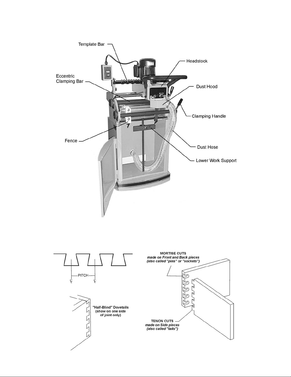
Features of the DT45 Dovetai ler .............................................................................................................. 7
Termino lo g y ............................................................................................................................................ 7
Unpac king ............................................................................................................................................... 8
Contents of the Shipping Container ...................................................................................................... 8
Installati on & Assembly ............................................................................................................................ 9
Installing Handle .................................................................................................................................. 9
Installing Switch ................................................................................................................................. 10
Installing Dust Hood ........................................................................................................................... 10
Installing Clamping Handles ............................................................................................................... 10
Dust Collection ................................................................................................................................... 10
Grounding Inst r uc tions ....................................................................................................................... 11
115 Volt Operati on ............................................................................................................................. 11
230 Volt Operati on ............................................................................................................................. 12
Extension cords ................................................................................................................................. 12
Adjustments .......................................................................................................................................... 13
Lower Work Support .......................................................................................................................... 13
Locking Handles ................................................................................................................................ 13
Clamping Ba r s ................................................................................................................. .................. 1 3
Template Bar ..................................................................................................................................... 14
Horizontal and Vertical Fences ........................................................................................................... 14
Buffer Pads ........................................................................................................................................ 16
Cutter Height ...................................................................................................................................... 16
Mortise Depth .................................................................................................................................... 1 6
Thickness of Tenon Cut ..................................................................................................................... 17
Tightness of Morti se/Tenon Fit ........................................................................................................... 17
Drive Belt Tension .............................................................................................................................. 18
Replacing Cutter ................................................................................................................................ 18
Operation .............................................................................................................................................. 1 8
Preventing Chip Out ........................................................................................................................... 20
Dovetails in Plywood .......................................................................................................................... 20
Maintenance .......................................................................................................................................... 21
Lubrication ......................................................................................................................................... 21
Replacement Parts ................................................................................................................................ 23
Parts List: Base Assembly .................................................................................................................. 24
Base Assembly .................................................................................................................................. 25
Parts List: Headstoc k A ssembly ......................................................................................................... 26
Headstock Assembly .......................................................................................................................... 27
Parts List: Cabinet Assembly .............................................................................................................. 28
Electri c al Connec tions – 115 volt ........................................................................................................... 29
Electri c al Connec tions – 230 volt ........................................................................................................... 30
3
Page 4

Warning
1. Read and understand the ent ire owner’s manual before att em pting assembly or operation.
2. Read and understand the warnings po sted on the m achine and i n thi s manual. Fail ure to comply wit h
all of these warnings m ay cause seriou s i njury.
3. Replace the warning labels if they become obscured or removed.
4. This dovetailer i s designed and i ntended f or use by pr operl y tr ained and ex peri enced personnel only .
If you are not familiar with the proper and safe operation of a dovetailer, do not use until proper
training and knowledge have been obtained.
5. Do not use this dovetailer for other than its intended use. If used for other purposes, Powermatic
disclaim s any real or i mplied warrant y and h olds itsel f harml ess from any injury t hat may r esult f rom
that use.
6. Al ways wear approved safety glasses/f ace shields while using thi s dovetailer. Everyday eyeglasses
only have impact resi stant lenses; they are not safet y glasses.
7. Before operating this dovetailer, remove tie, rings, watches and other jewelry, and roll sleeves up past
the elbows. Remove all l oose clothing and confine long hair. Non-slip f ootwear or anti-skid floor strips
are recommended. Do not wear gloves.
8. Wear ear protector s (plugs or muffs) during extended peri ods of oper ation.
9. Some dust created by power sanding, sawing, grinding, drilling and other construction activities
contain chemi cals known to cause cancer , bir th defects or other r eproductiv e harm . Some exampl es
of these chemic als are:
• Lead from lead based paint.
• Crystalli ne sil ic a from bricks, cement and other masonry pr oduc ts.
• Arsenic and chromium from chemically treated lumber.
Your risk of exposure varies, depending on how often you do this type of work. To reduce your
exposure to these chemicals, work in a well-ventilated area and work with approved safety
equipment, such as face or dust masks that are specifically designed to filter out microscopic
particles.
10. Do not oper ate this machine while tired or under t he influenc e of drugs, alcohol or any medic ation.
11. Mak e c er tain the switch is in the OFF position before connecting the machine to the power supply.
12. Mak e c er tain the machine is properly grounded.
13. Mak e all machine adjustment s or maintenance with the machine unplugged from the power source.
14. Remove adjusting keys and wrenches. Form a habit of checking to see that keys and adjusting
wrenches are removed from the machine before turning i t on.
15. Keep safety guards in place at all times when the machine is in use. If removed for maintenance
purposes, use extreme caution and replace the guards immediately.
16. Check damaged parts. Before further use of the machine, a guard or other part that is damaged
should be carefully checked to determine that it will operate properly and perform its intended
function. Chec k for alignment of moving par ts, binding of moving parts, breakage of parts, mounting
and any other condi ti ons that m ay affect its operati on. A guard or ot her part that i s damaged should
be properly repaired or replaced.
17. Pr ov ide for adequate space surrounding work area and non-glare, ov er head lighting.
18. Keep the floor around the machine cl ean and free of scrap material, oil and grease.
19. Keep v isitors a safe distance from the work area. Keep children away.
20. Mak e y our workshop chi ld proof with padlocks, m aster switc hes or by r em ov ing starter keys.
4
Page 5

21. Giv e your work undivi ded attention. Looki ng around, carryi ng on a conversati on and “horse-play” ar e
careless acts that can r esul t in serious injury.
22. Maintain a balanced stance at all tim es so that you do not fall or lean against the cutter or other
moving part s. Do not over r eac h or use excessive force to perform any machine oper ation.
23. Use the right tool at the correc t speed and f eed rat e. Do not force a t ool or att achment to do a job for
which it was not designed. T he ri ght tool will do the job better and saf er.
24. Use recommended accessories; improper accessories may be hazardous.
25. Mai ntain tools with care. Keep cutter s sharp and clean for the best and safest perf ormance. Follow
instructions for lubricating and changing accessories.
26. Make sure the work pi ece is securel y attached or clamped to the table. Never use your hand to hol d
the work piece.
27. T ur n off the machi ne before cleaning. Use a brush or compressed air to remove chips or debri s — do
not use your hands.
28. Do not stand on the machine. Serious injury c ould oc c ur if the mac hine tips over.
29. Never leave the machine r unning unatt ended. Turn the power off and do not leave t he machine until
cutter comes to a complete stop.
30. Remove loose items and unnecessary work piec es from the area before starting the machine.
Familiariz e you rself with the following safety notices used in this manual:
This means that if precautions are not heeded, it may result in mi nor i njury and/or
possible machine damage.
This means that if precautions are not heeded, it may result in serious injury or possibly
even death.
- - SAVE THESE INSTRUCTIONS - -
5
Page 6

Introduction
This manual is provided by Powermati c covering the safe operat ion and maintenance pr ocedures for a
Model DT45 Si ngle End Dov etailer. T his manual cont ains instr uctions on i nstallat ion, saf ety precauti ons,
general operating procedures, maintenance instructions and parts breakdown. This machine has been
designed and const ructed to pr ovide years of trouble free oper ation if used in accor dance to i nstructions
set fort h in t his manual . If there are any que sti ons or c om m ents, please co ntac t ei ther your l ocal suppli er
or Powermatic. Powermatic can also be reached at our web site: www.powermatic.com.
Description
The Model DT45 Dov etailer will make cleanly cut half-bl ind dovetails for drawer or box constr uction. A
four-si ded template allows any of four pi tches, from 1” up to 2-1/2”. T he use of different dovetail pitches
will give a unique custom appearance to y our work. T he cut ter is car bide-ti pped. The m achine i s built to
last with cast iron and steel construction. The manual clamping system is quick and easy to use.
Specifications
Model Number ...................................................................................................................................DT45
Stock Number...............................................................................................................................1791304
Minimum work pi ece size (in.) .................................................................................................7-7/8 x 2-3/8
Maximum work piece size (in.) ........................................................................................................ 31 x 11
Minimum dovetail height (in.) .............................................................................................................. 3/16
Maximum dovetai l height (in.) ............................................................................................................... 3/4
Minimum front thickness (in.) .............................................................................................................. 9/32
Maximum front thickness (in.) ............................................................................................................ 1-3/4
Minimum side thickness (in.) ............................................................................................................... 9/32
Maximum side thi ckness (in.) ........................................................................................................... 1-3/16
Number of spindl es .................................................................................................................................. 1
Spindle speed (RPM )...................................................................................................................... 18,500
Center-to-center dovetail spacing (in.) ....................................................................... 1, 1-1/2, 2, and 2-1/2
Table he ig h t from floor (in .) .................................................................................................................... 35
Overall dimensions (L x W x H) (in.) ........................................................................................ 33 x 33 x 61
Motor ....................................................................................... TEFC, 1HP, 1Ph, 115/230V (prewired 115)
Dust collection ports diameter (in.) .................................................................................. front 2-1/2, rear 4
Dust collection minimum CFM required ................................................................................................ 50 0
Approximate Weight, Shipping/Net (lbs.) ....................................................................................... 447/345
The above specifications were current at the time t his manual was published, but bec ause of our policy of
continuous im provement, Powerm atic reserves the right t o change specific ations at any time and without
prior notic e, wit hout incurring obligations.
6
Page 7
Features of the DT45 Dovetailer
Terminology
Below are the term s used in t his manual to identify types of cuts and measurement s.
7
Page 8
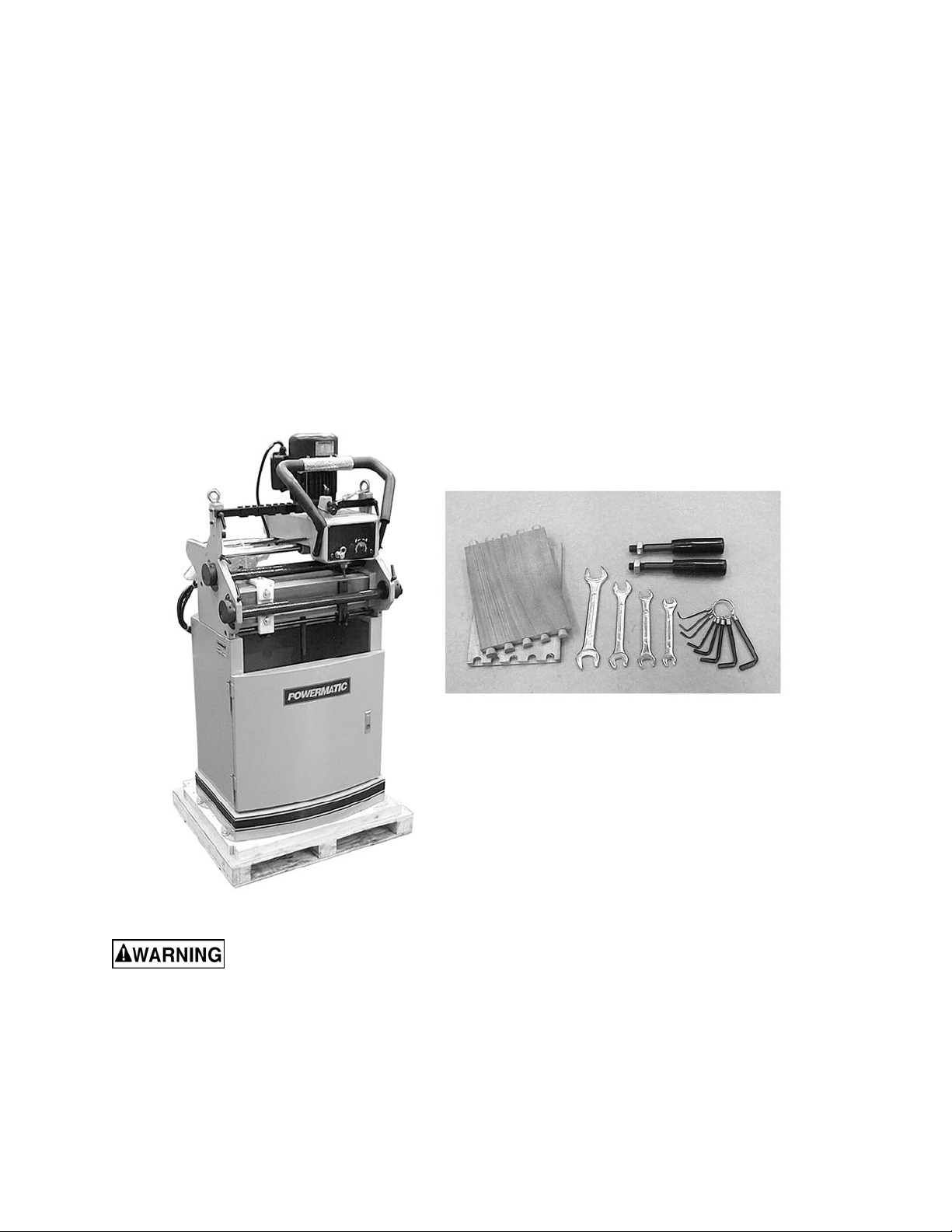
Unpacking
Open shipping cont ainer and check f or shipping
damage. Report any damage immediately to
your distributor and shipping agent. Do not
discard any shi pping m at erial until t he dov etailer
is assembled and r unning pr oper ly.
Remove the box from inside the cabinet.
Compare the c ontent s of y our cont ainer wit h t he
following parts list to make sure all parts are
intact. Mi ssing parts, if any, should be reported
to your distributor. Read the instruction manual
thoroughly for assembly, maintenance and
safety instructions.
Contents of the Shipping Container
1 Dovetail Machine
2 Clamping Handles (wit h hex nuts)
1 Set of Open-Ended W r enc hes (8-10, 11-13,
12-14 and 17-19mm)
1 Set of Hex Wrenches (1.5 to 6mm)
2 Sample Dovetailed B oar ds
1 Owner's Manual
1 Warranty Card
Read and understand the entire contents of this manual before attempting set-up
or operation! Failure t o co mply may cause serious injury.
8
Page 9
Installation & Assembly
Tools requi red for assemb ly
forklift or hoist with straps/slings
11mm wrench (provided)
[NOTE: A socket set wi th ratchet wrench may
speed assembly ]
4 and 5mm hex wrenches (provided)
knife or wire cutter
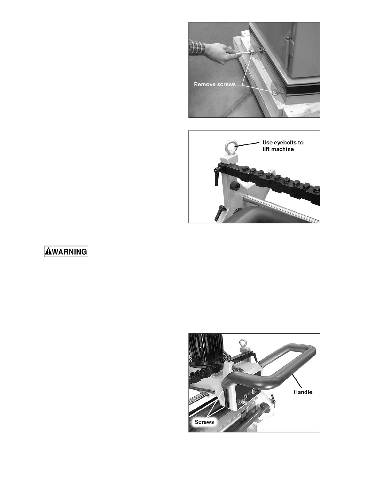
1. Remove the four screws and flat washers
holding the machine to the pallet with an
11mm wrench, as shown in Figur e 1.
2. Place lifti ng st r aps thr ough the two eyebolts
at the top of the m achine (Figure 2). Using
a forklift or hoist, lift the machine off the
pallet and into its desired location. The
Dovetail er should be located in a dry area
with sufficient lighting. Leave plenty of
space around the machine for operations
and routine maintenance work.
3. W hen the machine is sit uated, the eyebolts
(Figure 2) can be left on the machine, or
unscrewed and rem oved, if so desi red. Be
sure to retain the eye bolts for future use.
4. If desired, the Dovetailer can be further
stabilized by securing it to the floor, using
lag screws through the four holes at the
bottom of the cabinet.
Figure 1
Figure 2
The dovetailer should be
unplugged from the power source during
assembly pro cedu res.
5. A cord holds the headstock secure to an
eyebolt to prevent the headstock from
moving during shipping. This cord should
now be cut and removed.
6. Exposed metal areas of the dovetailer
(such as the table, template bar, clamp
bars, rods, etc.) have been factory coated
with a protect ant. This should be remov ed
with a soft cloth dampened with kerosene
or mineral spirits. Do not use an abrasive
pad. Do not let solvent contact plastic or
rubber parts as it may damage t hem .
Installing Handle
The rubber-cov ered handle (Figure 3) has been
placed backwards for shipping purposes, and
must be reversed befor e oper ating the machine.
1. Remove the four socket head cap screws
from the headstock (two of them are holdi ng
the handle), and t urn the handl e around as
shown in Figure 3.
2. Secur e the handle to the headstock with all
four socket head cap screws.
Figure 3
9
Page 10
3. Tighten the f our socket head c ap screws.
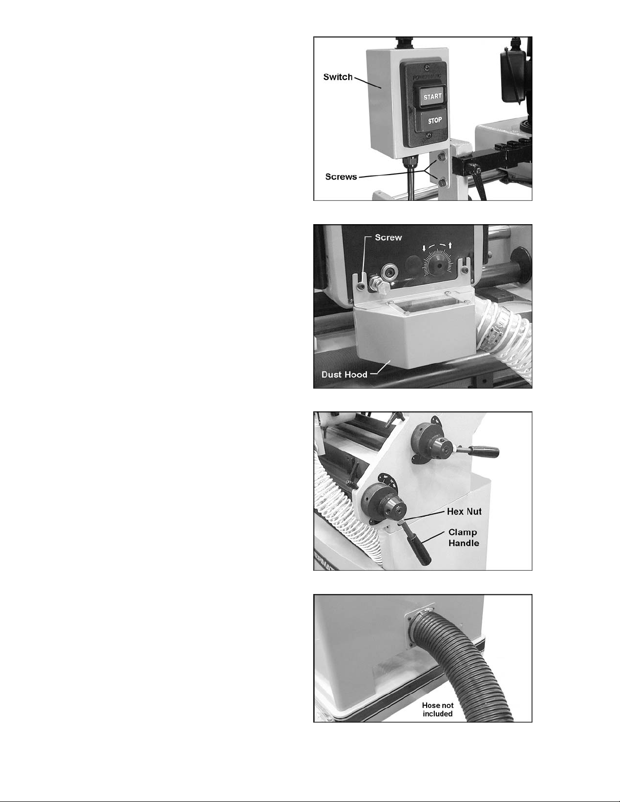
Installing Switch
1. Remove any protective wrapping from the
switch.
2. Remove the two socket head cap screws
fr om th ei r h ol es o n t he lef t si de of t h e fr am e
with a 5mm hex wrench. See Figure 4.
3. Pl ace the flange of the switch box ov er the
holes, and re-i nsert the two socket head cap
screws, as shown in Figur e 4.
4. Tighten both socket head c ap screws.
Installing Dust Hood
1. Open the cabinet door a nd pull out the dust
hood, which is connect ed to a hose.
2. Loosen the two sock et head cap scre ws on
the front of the headstock (Fi gure 5) with a
4mm hex wrench.
3. Slide the flanges of the dust hood behind
the screws and fl at washers as shown.
4. Tighten both socket head c ap screws.
Installing Clamping Handles
There are two hubs at the right side of the
machine which are used for clamping (Figur e 6).
Screw one clam p handle into a threaded hol e on
each hub. (Each hub has three such holes –
choose one that will prevent the clamping
handles from confl ic ting with each other.)
Figure 4
Figure 5
When the clamping handles are screwed in
completely, tighten the hex nuts against the
hubs with a 19mm wrench.
Dust Collection
The use of a dust collection system is
recommended f or this machi ne. It will help k eep
your shop clean as well as mi nimize any healt h
risks caused by wood dust. Mak e sure your dust
collector has a capacity of at least 500 CFM.
Connect the intake hose of your dust c ollector to
the 4” diameter port at t he back of the cabinet.
See Figure 7.
NOTE: A variet y of dust coll ection systems are
available from Powermatic. Call customer
service at 1-800-274-6848 or visit our website
for mo re inform ation.
Figure 6
Figure 7
10
Page 11

Grounding Instructions
Electrical connections must
be made by a qualified electrician in
compliance with all relevant codes. This
machine must be properly grounded to help
prevent electrical shock and possible fatal
injury.
This mac hine m ust be grounded. I n the event of
a malfuncti on or break down, groundi ng prov i des
a path of least r esistance f or electri c current to
reduce the ri sk of el ectric shock. This dov etailer
is equipped with an electric cord having an
equipment-grounding conductor and a
grounding plug similar to the one illustrated in
Figure 8. The plug must be inserted into a
matching outlet that is properly installed and
grounded in accordanc e wit h al l loc al codes and
ordinances.
Do not modify the pl ug provided. If it will not fit
the outlet, have the proper out let installed by a
qualified elec trician.
Improper connection of the equipmentgrounding conductor can result in a risk of
electric shock. The conductor, with insulation
having an outer surface that is green with or
without yellow stripes, is the equipmentgrounding conduct or . If repair or replacement of
the electric cord or plug is necessary, do not
connect the equipment-grounding conduc tor to a
live terminal.
Check with a qualified electrician or service
personnel if the grounding instructions are not
completely understood, or if in doubt as to
whether the tool i s properly grounded. Us e only
three wire extensi on c or ds that have three-prong
grounding plugs and three- pole recept acles that
accept the tool ’s pl ug.
Repair or replace a damaged or worn cord
immediately.
Make sure the voltage of your power supply
matches the specif ications on the m otor plate of
the machine.
Figure 8
115 Volt Operation
As received f rom the factory, your dov etailer is
ready to run at 115 volt operation. This
dovetail er, when wired f or 115 v olts, i s intended
for use on a ci r cuit t hat has an outl et and a pl ug
that look li ke the ones illustrat ed in Figure 8. A
temporary adapt er, which looks li ke the adapter
as illustrated in Figure 9, may be used to
connect this plug to a two-pole receptacle, as
shown in Figures 8 and 9, if a properly gr ounded
outlet is not av ailable.
Figure 9
11
Page 12

A
The temporary adapter should only be used unt il
a properly grounded out let c an be installed by a
qualified electrician. This adapter is not
applicable in Canada. The green colored rigi d
ear, lug, or tab, extending from the adapter,
must be connect ed to a perm anent ground such
as a properly grounded outl et box, as shown in
Figure 9.
230 Volt Operation
If 230 volt, single-phase operation i s desired, the
following instructions must be followed to
convert fr om 115 to 230:
1. Disconnect machine from power source.
2. This dovetailer is supplied with six motor
leads that are connected for 115 volt
operation, as shown in Figure 10.
Reconnect these six motor leads for 230
volt operation, also shown in Figure 10.
3. The 115 volt attachment plug (Figure 8),
supplied with the dovetailer, must be
replaced with a UL/ CSA listed plug suitable
for 230 volt operation, similar to the one
illustrated in Figure 11. Contact your local
authorized W MH Tool Group service center
or qualifi ed el ectrician f or proper pr ocedures
to install the plug. The dovetailer must
comply with all local and national codes
after the 230 volt plug is installed.
4. The dovetailer with a 230 volt plug should
only be connected to an outlet having the
same confi guration. No adapter is av ailable
or should be used with the 230 v olt plug.
Important: In all cases (115 or 230 volts),
make certain the receptacle in question is
properl y grounded. I f you are n ot sure, have
a registered electrician check the receptacle.
Extens ion cords
If an extensi on c or d is necessary, make sure t he
cord rating i s suitable for the am perage listed on
the machine’s motor plate. An undersized cord
will cause a drop in line voltage resulting in loss
of power and overheating.
Use the chart i n F igur e 12 as a gener al gui de i n
choosing the c orrect size cord. If in doubt, use
the next heavi er gauge. The smaller the gauge
number, the heavier the cord.
Figure 10
Figure 11
WG (American Wire Gauge)
Cord Length
240 Volt Lines 120 Volt Lines
0-50 Feet No. 16 No. 16
50-100 F eet No. 14 No. 14
Over 100 Feet No. 14 No. 12
Figure 12
12
Page 13

Adjustments
Disconnect machine from
power source before making adjustments.
Failure to compl y may cause seri ou s injury.
Lower Work Support
Inside the cabinet is a lower work support
(Figure 13) whic h is used to support work piec es
in the verti cal position. To move t his support up
or down, loosen the locking handle (A, Figure
13). Tighten loc ki ng handle when finished.
To set the work support at l evel positi on, loosen
the socket head c ap scre w (B, F igur e 13) with a
6mm hex wrench, and loosen the l oc king handle
(C, Figure 13). When finished adjusting, t ighten
locking handle (C, Figure 13) and socket head
cap screw (B, Figur e 13).
Locking Handles
All locking handles (such as C, Figure 13) can
be rotated if they are in the way of other
machine parts. Simply lift straight out on the
locking handle and rotate it, then release,
making sure it seats properly.
Figure 13
Clamping Bars
The workpieces are clamped to the table by
eccentric bars. Simply rotate the handle (A,
Figure 14) until the workpiece is secured. Do not
overtighten the clamping bars to prevent denting
the workpiece.
Both upper and lower clamping bars must be
adjusted to match the thickness of your
workpieces. Thickness is indicated on the
adjoining scal es mounted to the machine frame.
1. Loosen the t wo locki ng handles on the front
edge of the frame (B, Figure 14).
2. Rotate the knurled adjustment pieces (C,
Figure 14) on both sides of the machine
until the indicator line on the adjustment
piece matc hes the desired thi ckness on the
adjoining scale. It is important that both
knurled adjustment pieces be rotated the
same to ensure the clamping bar is parallel
to the table.
3. Tighten loc ki ng handles (B, Figure 14).
Figure 14
(shows adjustment of lower clamping bar)
13
Page 14

Template Bar
The four-sided template bar, shown in Figure
16, will allow you t o create “half-bli nd” dovetail s,
where the dovetail s are visible on only one side
of the joint. It will create dovetails in one of f our
different “pitches” or centerlines. The available
pitches are 1”, 1-1/2”, 2” and 2-1/2”. To change
the pitch of a dovetail c ut, pr oc eed as follows:
1. Release one end of the spring on the left
side of the head stock (Figure 15) and pul l
the headstock toward the front of the
machine until the tracer pin is clear of the
template bar as shown in Figur e 16.
2. Loosen and r emove the locking handl e on
each end of the templ ate bar.
3. Pull out the template bar as shown in
Figure 16, flip it to the desired side, then reinstall it. NOTE: The pitch dimension is
inscribed on each si de of t he template bar.
4. Insert and ti ghten both locking handles.
5. Push the headstock back and re-connect
the spring (Figur e 15) .
Horizontal and Vertical Fences
Figure 15
The workpieces will lie flush against the f ences
during cutti ng to ensure squarene ss. Two buff er
pads made of polyethylene material are
mounted to the fences – these provide a
“chipbreaker” effect to prevent chip-out on the
left edges of t he workpieces. T hey ar e de signed
so the cutter can bite into them without any
damage to the cutter .
To adjust these fenc es, pr oc eed as follows:
1. Place your F RONT/BACK workpiece on the
horizontal table and against the fence. Move
the headstock to the left edge of the
workpiece, then sl ide it to the ri ght, all owing
the tracer pin to slide just a little into the
template recesses. This will give you an
idea where the cuts will be made and how
they will be spaced acros s the width of the
workpiece.
2. For broad m ov em ent of the horizontal fence,
loosen both locking handles on the
horizontal fence (A and B, Figure 17) and
slide the horizontal fence into position.
There is also a micro adjustment on the
horizontal fence; loosen locking handle (A,
Figure 17), but leave locking handle (B)
tight. Loosen the screw (C, Figur e 17) with a
6mm hex wrench and rotate the knurled
knob (D, Figure 17) as needed for precise
positioning of the horizontal fence. When
finished, tighten screw (C, Figure 17) and
locking handl e ( A, Figure 17) .
Figure 16
Figure 17
14
Page 15

3. Conti nue t o check the spaci ng by slidi ng the
headstock acros s, until the dov etail cuts will
be distribut ed ev enly acr oss the width of t he
workpiece. NOTE: This is an approximate
method of determining by eye where to
place the workpi ece. A scale in inches and
millimeters is mounted to the table if you
need more precise measurements for the
location of the dov etail cuts.
4. As noted, the position of the horizontal
fence will affect the position of the vertical
fence. Ther efore, if you are making a drawer
that has a bottom groove, the vertic al fence
should be set so that the bottom groov e in
the drawer piece to be tenoned will go
through the cent er of a dovetail. That means
the bottom gr oove of t he mortised piec e will
go through the center of a mortise. This will
prevent t he groov e from bei ng vi sible on t he
outside of the assembled drawer. See
Figure 18 and 19.
5. Tighten the locking handles on the
horizontal fence t o secure it in posit ion. The
position of the hori zontal fence will be used
as the basis for locati ng the vertical fence.
Figure 18
6. Loosen the locking handle on the vertical
fence.
Important: To make proper dovetail cuts, the
two fences must always be offset from each
other by half the pitch of the template bar. That
is, off set 1/ 2” when using t he one- inc h tem plat e;
3/4” when using the 1-1/2 inch template; 1”
when using the two-inch template, and 1-1/4”
when using the 2-1/2 inch template. The
measuring scales on the table are marked in
1/16” incr em ents.
7. Li ne up the v erti cal f ence with t he hori zont al
fence, then offset the vertical fence by
exactly half the pitch of the template. See
Figure 20.
8. This adjustm ent will cause the vertical work
piece to be sli ghtly offset to t he right of the
horizontal pi ece, thus ensuring the dov etail s
will correspond when the two pieces are
assembled.
9. Tighten the locking handle on the vertical
fence.
There are a total of four fences on the DT45
Dovetailer – two vertical and two horizontal.
These allow tw o sets of workpiece s to be cut at
the same time. If this is desired, position the
other two fences in the sam e manner as the first
two fences, remembering again to offset the
vertical fence by half t he pitch.
Figure 19
Figure 20
15
Page 16

Buffer Pads
The polyethylene buffer pads (shown in Figure
20) have slots through which they are secured
to the fences by screws. These buffer pads at
times may need to be re-positioned; for
example, if a clamping bar is adjusted for a
different thickness of workpiece, t he buffer pad
may need to be adjusted out of the way to
prevent obstr uc ting the clamping bar.
To adjust a buff er pad, loosen the t wo hex cap
screws (Figure 20) with a 13mm wrench. Slide
the buff er pad as necessary. Reti ghten bot h hex
cap screws when finished.
Cutter Height
This adjustment will change the height of the
tails on the tenon (m ale) cut, and how deep the
mortise (female) cut goes into the thickness of
the workpiece.
1. Disconnect machine from power source.
2. Loosen the spindle lock screw (Figure 21)
by turning it counterclockwise with a 6mm
hex wrench.
3. Tur n the s pindl e hei ght adj ust scre w (Fi gure
19) with a 5.5mm hex wrench, either
clockwise to raise the cutter (decrease the
cutter depth), or counterclockwise to lower
the cutter (incr ease the c utter depth).
4. Tighten spindle lock screw by turning it
clockwise.
Mortise Depth
This adjustm ent ensures that t he side pieces of
your drawer will remain flush with the front and
back pieces of the drawer. The correct fit will
have the sides f lush with the fr ont and back of
the drawer, wit hout showing any of the morti se
cut on the inside of the dr awer.
The mortise depth adjust bolt, shown in Figure
19, limits how f ar for ward the cutt i ng unit will go,
and thus limits the length of your mortise cut.
1. Disconnect machine from power source.
2. Loosen the hex nut on the mortise depth
adjust bolt ( Figure 21) by turni ng the hex nut
countercl oc k wise with a 17mm wrench.
3. To decrease the depth of the mortise
(female) cut, turn the bolt clockwise. To
increase the depth of the mortise cut, turn
the bolt counter cl oc k wise.
4. Re-tighten the hex nut.
Figure 21
16
Page 17

Thickness of Tenon Cut
To adjust the t hickness of the t enon (male) cuts,
you will change the depth of the tracer pin
(Figure 22).
1. Disconnect machine from power source.
2. Loosen the lock ing handle on top the tr acer
pin (Figure 22) by turning it counter
clockwise.
3. Insert a 5. 5mm hex wrench into the end of
the adjustment screw (Figure 22) and turn
the adjustment screw as needed. To
decrease the thic k nes s of the tenon cut, t ur n
the adjustment screw counterclockwise. To
increase the thi ckness of t he tenon cut, tur n
the adjustment screw cl oc k wise.
4. Tighten locking handle.
Figure 22
Tightness of Mortise/Tenon Fit
A proper dovetail fit should be snug with no
gaps showing, but not ov erly tight as gl ue must
later fill the joints. If the cuts seem correct, but
the joint is simply too tight, or the joint is too
loose, proceed as f ollows.
1. Disconnect machine from power source.
2. Remove the dust hood f rom the front of the
machine.
3. You will notice the cutter, shown in Figure
23, is slight ly off c enter of the spindle. The
spindle is eccent ric and allows the cutter t o
be turned to a different position on the
spindle.
T he cutter is very sh arp! Use
caution when working with or around it.
4. Loosen both set screws on the spindle
(Figure 23) by turning them counterclockwise with a 4mm hex wrench.
5. A scal e is l ocat ed just above the cut ter , wit h
a plus (+) and minus (-) sign. Moving the
cutting edge of the cutter toward the plus (+)
side of the scale wil l i ncrease the si ze of the
mortise cut and decrease the size of the
tenon cut. Moving the cutting edge of the
cutter toward the minus (-) side will
decrease the size of the mortise cut and
increase the size of the tenon cut.
Figure 23
6. With your fi nger s on the shank porti on of the
cutter, carefully rotate the cutter toward the
plus (+) or minus (-) position as needed.
7. When satisfied with the adjustment, tighten
both set screws fi rmly.
8. Re-attach t he dust hood.
17
Page 18

Drive Belt Tension
The tight ness of the belt that drives the spi ndle
has been adjusted at the factory. Further
adjustment may be nec essary af t er the m achi ne
receives some use, as the belt may stretch
slightly duri ng the “breaking in” process.
Belt tensi on can be adjusted by a socket head
cap screw at t he rear of the headstoc k (Figure
24) which slides the mot or toward or away from
the spindle. To tighten the belt, rotate this cap
screw clockwise with a 6mm hex wrench. To
loosen the belt, rotate the cap screw
counterclockwise. The belt should be just tight
enough to prevent it slipping on the spindle
during operation.
Figure 24
Replacing Cutter
T he cutter is very sharp ; use
caution when working with or around cutter.
Disconnect machine from power source!
Failure to compl y may cause seri ou s injury.
To replace the cutter, loosen both set screws
(Figure 23) and caref ull y pull down on t he c utt er
until it is free from the spindle. Place the new
cutter in the spindle and tighten both set screws.
Operation
NOTE: The following are basic dovetailing
procedures as they apply to this machine, and
are not intended to be a full course of instruction
in making dovetails. Refer back to the
terminology on page 7 if needed.
The Dovetailer can be used to make joints in
drawers, boxes, cabinets, etc. Instruc tions in this
manual are based upon making a drawer
consisting of FRONT and BACK pieces, and two
SIDE pieces. FRONT and BACK pieces are
placed horizontally on top the machine’s table;
SIDE pieces are plac ed vertically in front of the
machine’s table. The insides of the boards
always face outward when they are placed on
the machine.
No matter the project, prevent mistakes by
laying out the pieces beforehand according to
how they will be assembled. Place them with the
inside f acing up, and l abel the m ati ng edges, as
shown in Figure 25.
Before cutting on what is to be the finished
piece, the operator should make test cuts on
scrap wood to make sure all settings and
adjustments are correct.
Figure 25
18
Page 19

IMPORTANT: Make sure the workpiece has
been cut square before making dovetails. An
out-of-square workpiece will result in poor
do vetail joints.
1. Set the appropriate template size, fence
positions, clamping bar thic k ness, and cut ter
depth for your particular job. Refer to
“Adjustment s” section starting on page 13.
2. Mov e the headstock all the way to the right
and out of the way.
3. Place the dr awer BACK on top the table and
flush against the fence, with the bottom
groove faci ng up and toward the f ence. See
Figure 26.
Figure 26
4. Place the drawer RI GHT SIDE in the verti c al
position on t op the lower work support and
against the fence. Adjust the lower work
support as necessary. The bottom groove
on the RIGHT SIDE should be toward the
fence and faci ng the operator, as shown in
Figure 26.
5. Make the BACK butt against the RIGHT
SIDE so they are flush, with the RIGHT
SIDE overlapping the edge of the BACK.
See Figure 26. Both pieces should be fi rmly
and evenly against the fences with their
edges flush as shown. You may need to
loosen and tighten each clamping bar
several tim es as you adjust the two drawer
pieces into position. When the drawer
pieces are positioned correctly, tighten
upper and lower clamping bars. Do not
overtighten the clamping bars.
6. Slide the headstock all the way to the left.
Turn on the machine and m ove the cutter in
sequence, left to right, allowing the tracer
pin to m ove i n and out of the templat e slot s.
See Figure 27. You can watch the pr ogress
of the cut through the window of the dust
hood. NOTE: Do not r ush the cut; allow the
cutting unit to do the work.
7. When finished, slide the headstock out of
the way and unclam p the workpi ec es.
8. Fit the BAC K and RIGHT SIDE together and
examine the joint. If the joint is not
satisfactory, make any needed corrections
to your settings as explained under
“Adjustments.” If the joint is satisfactory,
proceed with the next cut as follows.
9. Turn the B ACK 180 degrees and clam p it in
the horizontal position against the fence.
Figure 27
(Dust hood removed f or clarity only; always use
dust hood when operat ing dovetail machine.)
19
Page 20

10. Insert t he LEFT SIDE piece and cl amp it in
vertical position on the lower work support
and against the fence. (NOTE: The bottom
grooves on both pi eces will be face up, but
will now be opposite the fences.) Again,
make sure the edges are flush with the
LEFT SIDE overlapping the edge of the
BACK.
11. Conti nue the dovetailing procedur e with the
FRONT piece, making cuts “C” and “D”
(Figure 25) until all f our joints of t he drawer
have been cut.
TIP: When using drawer side widths that are not
“whole inch” sizes, you may wish to gauge off
the top of the drawer rather than the bottom
when placing workpi eces in the machine. Doi ng
this will improve the look of the drawer by
providing a f ull t enon near the top of the drawer
and the half-tenon will end up at the bottom. See
Figure 28.
Preventing Chip Out
As noted previously, when the SIDE and
FRONT/BACK pieces are inserted into the
machine, they are offset a bit so they’ll match
correctly when assembled. In other words, the
SIDE will rest slightly to the right of the
FRONT/BACK in the machine. This leaves the
right edge of the SIDE exposed without the
“chipbreaker” effect that the FRONT/BACK
provides for the rest of the SIDE (see Figure
29). Thi s may result in an unsatisfact ory cut at
the edge of the SIDE.
Figure 28
This problem is resolved sim ply by taking a 2inch-plus wide “back-up” board, of the same
thickness as your workpiece, and clamping it
horizontall y next to the FRONT/BACK pi ece so
that it backs up t he exposed edge of the SIDE,
as shown in Figur e 29. You can use this piece
over and over again.
Dovetails in Plywood
Because plywood handles a bit differently than
solid stock, her e ar e some ti ps to follow:
1. When usi ng plywood, the lay ers tend to be
more fr agile. T herefore, t he operat or should
keep the movement of the cutting unit
consistent and proceed relatively slowly.
2. On t he rounded arcs of the tenon cuts, you
may lose a bit of t he top layer . This is to be
expected wit h plywood, and does not affect
either the look or the strength of the
assembled dovetail joint. Rather, the
strength of the dovetailed corner comes
from the flat side of the tenons.
Figure 29
20
Page 21

3. Plywood has a tendency to chip out on
exposed edges. A back -up board should be
used as needed (see Figure 29) .
Maintenance
Before doing maintenance
on the machine, disconnect it from the
electrical supply. Failure to comply may
cause serious inj ury.
If the power cord is worn, cut, or damaged in
any way, have it repl ac ed immediately.
The table and other ex posed metal part s should
be kept clean and f ree of rust. A coat of paste
wax will help protec t t he table from tarnishing.
After each day ’s u se, br ush or blow out dust and
debris from t he cutter, table, motor, etc.
Keep the clam ping bars clean to prev ent debri s
adhering to them, whic h c an scar workpieces.
Keep clean the travel rods upon which the
headstock slides.
Lubrication
The linear bushings by which the headstock
travels on the rods are pre-lubricated and
sealed; they do not r equir e additional lubrication.
The spindle bearing should be lubricated as
needed, accordi ng to machine usage. Apply VG120 grease through the grease nipple on the
spindle (#10 i n the exploded v iew on page 27).
21
Page 22

Troubleshooting the DT45
Trouble Probable Cause Remedy
Machine will not
start/restart or
repeatedly trips
circuit breaker s or
blo ws fuses.
Machine not plugged in. Verify machine is connected to power.
Fuse blown, or cir c uit
breaker tripped.
Cord damaged. Replace cord.
Overload automatic reset
has not reset.
Dovetailer frequently trips.
Building circuit breaker trips
or fuse blows.
Loose electri c al
connections.
Motor starter failure.
Motor failure.
Miswiring of the unit.
Replace fuse, or r eset ci r c uit breaker.
If the Dovetailer overloads on the circuit breaker
built in to the motor starter, it takes time for the
machine to cool down befor e r estar t. Allow unit to
adquately cool before attempting restart . If pr oblem
persists, check am p setting on the motor starter
inside the electrical box.
Check the amp setting on the overload relay.
Match the full l oad am ps on the motor as noted on
the motor plat e. If am p setting is correct then there
is probably a loose elec trical lead or a failed
component. See below.
Verify that dovetailer is on a circuit of correct siz e.
If circuit siz e is corr ect, there is probably a loose
electric al lead. Check amp setting on motor starter.
Go through all of the electrical connections on the
dovetailer including motor connections, verifying
the tightness of eac h. Look for any signs of
electric al ar ci ng whic h is a sure i ndicator of loose
connection or ci rcuit ov erl oad.
If you have access to a voltmeter, you can
separate a starter failure from a motor failure by
first, verifying incoming voltage at 220+/-20 and
second, checking the voltage between starter and
motor at 220+/- 20. If incoming voltage is incorrect,
you have a power supply problem. If voltage
between starter and motor is incorrect, you hav e a
starter probl em . If v oltage between starter and
motor is correct , you hav e a motor problem.
If electri c mot or i s suspect, y ou have two options:
Have a qualifi ed elect ri c ian test the motor for
function or rem ov e the motor and take it to a
qualified elec tric motor repair shop and have it
tested.
Check to make certain all electrical connections
are correct and pr operl y tight. The electrical
connections other than the motor are
preassembled and tested at the factory. Theref or e,
the motor connections should be checked as the
highest probability for error. If problem s persist ,
double check t he factory wiring.
22
Page 23

Trouble Probable Cause Remedy
Machine will not
start/restart or
repeatedly trips
circuit breaker s or
blo ws fuses.
(continued)
Cutter not cutting
properly.
Dovetailed parts fit
too tightly.
Dovetailed parts fit
too loosely.
Cutter sometimes
slips and misses
revolutions.
Dovetailed parts fit
side to side, but
have depth gaps
between the
mortise and tenon
cuts.
On/off switch failure. If the on/off switch is suspect, you have two
options: Hav e a qualified electrician test the switch
for functi on, or pur c hase a new on/off swit c h and
establish if t hat was the problem on changeout.
Cutter in wrong position. Turn cutter t owards the (+) or (-) mark [page 17].
Cutter dull or damaged. Sharpen or replac e c utt er .
Cutter not adjusted
properly.
Cutter not adjusted
properly.
Spindle belt t ensi on
incorrect.
The mortise depth or tenon
thickness is set incorrectly.
Loosen set screws and turn cut ter toward the (+)
mark. Retighten set screws [page 17].
Loosen set screws and turn cutter toward the (-)
mark. Retighten set screws [page 17].
Adjust spindl e belt tension [page 18].
Change depth of morti se cut or thick ness of tenon
cut by using the adjustm ent screw [pages 16 & 17].
A gap between
mortise and tenon
cuts increases
along the
dovetailed corner.
Side piece edge is
not aligned with
front/bac k piec e
edge.
Workpiec e sli ps
during the cut.
Boards not square when
clamped.
Fences not set correctly. Offset the vertical fence from the horizontal fence
Clamping bar not pr oper ly
adjusted for t hic k ness of
workpiece.
Make sure the initi al c uts on the board (ripping
and/or crosscutting) have been done squarely, and
that the board is flush agai nst the stop before
clamping.
by half the pitch of the cut.
Position cl am ping bar ac c or ding to workpiece
thickness. Make sure bot h ends of clamping bar
have been adjusted equally.
Replacement Parts
Replacement par ts are li sted on the f ollowing page s. To order parts or reac h our servi ce depar tm ent, call
1-800-274-6848, Monday through Friday (see our website for business hours, www.powermatic.com).
Having the Model Number and Serial Number of your mac hine available when you cal l will allow us to
serve you quickly and accurately.
23
Page 24

Parts List: Base Assembly
Index No. Part No. Description Size Qty
1 ............... DT45-101 .................Worktable .............................................................................................. 1
2 ............... DT45-102 .................Base Guide Rod .................................................................................... 2
3 ............... TS-1523041 .............Socket Set Screw ...............................................M6x12 ...................... 15
4 ............... DT45-104 .................Copying Template ................................................................................. 1
5 ............... DT45-105 .................Locking Handle ...................................................M6x35 ........................ 2
6 ............... DT45-106 .................Scale ..................................................................................................... 2
7 ............... DT45-107 .................Scale ..................................................................................................... 2
8 ............... DT45-108 .................Adjustment Piece................................................................................... 2
9 ............... DT45-109 .................C lamp Bar ............................................................................................. 2
10 ............. DT45-110 .................Key.....................................................................6x6x3 0 ....................... 2
11 ............. DT45-111 .................Hub ....................................................................................................... 2
12 ............. TS-1540081 .............Hex Nut ..............................................................M12 ............................ 2
13 ............. DT45-113 .................Lever ..................................................................................................... 2
14 ............. DT45-114 .................Handle................................................................................................... 2
15 ............. DT45-115 .................Locking Handle ...................................................M6x25 ........................ 2
16 ............. DT45-116 .................Locking Handle ...................................................M6x45 ........................ 2
17 ............. DT45-117 .................Sliding Rod ............................................................................................ 2
18 ............. DT45-118 .................Adjustment Piece................................................................................... 2
19 ............. DT45-119 .................Fence .................................................................................................... 2
20 ............. DT45-120 .................Locking Handle ...................................................M8x25 ........................ 6
21 ............. TS-1504061 .............Socket Head Cap Screw .....................................M8x30 ........................ 1
22 ............. DT45-122 .................Buffer Pad ............................................................................................. 2
23 ............. TS-1550061 .............Flat Wash er ........................................................M8 .............................. 9
24 ............. TS-1490031 .............Hex Cap Screw ..................................................M 8 x20 ........................ 8
25 ............. DT45-125 .................Buffer Pad ............................................................................................. 2
26 ............. DT45-126 .................Adjustment Screw.................................................................................. 1
27 ............. TS-
28 ............. DT45-128 .................Knurled Knob......................................................................................... 1
29 ............. DT45-129 .................Adjustment Seat .................................................................................... 1
30 ............. DT45-130 .................Guide Rod ............................................................................................. 1
31 ............. DT45-131 .................Clamping S e a t ....................................................................................... 1
32 ............. DT45-132 .................Locking Handle ...................................................M8x35 ........................ 1
33 ............. DT45-133 .................Adjustment Plate ................................................................................... 1
34 ............. TS-1504041 .............Socket Head Cap Screw .....................................M8x20 ........................ 1
35 ............. DT45-135 .................Switch Box ............................................................................................ 1
36 ............. TS-1550041 .............Flat Wash er ........................................................M6 .............................. 2
37 ............. TS-1503041 .............Socket Head Cap Screw .....................................M6x16 ........................ 2
38 ............. DT45-138 .................Contacto r .............................................................................................. 1
39 ............. DT45-139 .................Switch Cover ......................................................................................... 1
40 ............. TS-1502031 .............Socket Head Cap Screw .....................................M5x12 ........................ 2
41 ............. DT45-141 .................Scale ..................................................................................................... 2
42 ............. DT45-142 .................Buffer Pad ............................................................................................. 2
43 ............. TS-1550041 .............Flat Wash er ........................................................M6 .............................. 2
44 ............. TS-1503051 .............Socket Head Cap Screw .....................................M6x20 ........................ 2
45 ............. TS-1524041 .............Socket Set Screw ...............................................M8 x16 ........................ 1
46 ............. TS-2361081 .............Lock Washer ......................................................M8 .............................. 3
47 ............. DT45-147 .................Fence .................................................................................................... 2
1504071 .............Socket Head Cap Screw .....................................M8 x35 ........................ 2
24
Page 25

Base Assembly
25
Page 26

Parts List: Headstock Assembly
Index No. Part No. Description Size Qty
1 ............... DT45-201 .................Spindle Assembly (Index #2 thru #10) .................................................... 1
2 ............... DT45-202 .................Sp in d le B e a rin g Hou sing ....................................................................... 1
3 ............... DT45-203 .................Ball Bearing (special) ..........................................6005 B.P63 ................ 2
4 ............... DT45-204 .................Fixing Nut .............................................................................................. 1
5 ............... DT45-205 .................Eccentric Spindle ................................................................................... 1
6 ............... TS-1524021 .............Socket Set Screw ...............................................M8x10 ........................ 2
7 ............... DT45-207 .................Sp acer................................................................................................... 1
8 ............... DT45-208 .................Disc Spring ............................................................................................ 4
9 ............... DT45-209 .................Fixing Nut .............................................................................................. 1
10 ............. DT45-210 .................Grease Nipple ....................................................................................... 1
11 ............. DT45-211 .................Spindle Sl id e Seat ................................................................................. 1
12 ............. DT45-212 .................Gear Shaft ............................................................................................. 1
13 ............. TS-1550061 .............Flat Washer ........................................................M8 ............................. 1
14 ............. TS-1490031 .............Hex Cap Screw ..................................................M 8 x20 ....................... 1
15 ............. DT45-215 .................Clamping P ie ce ..................................................................................... 1
16 ............. DT45-216 .................Bushing ................................................................................................. 1
17 ............. TS-1504121 .............Socket Head Cap Screw .....................................M8x60 ........................ 1
18 ............. DT45-218 .................Panel ..................................................................................................... 1
19 ............. DT45-219 .................Plug ....................................................................................................... 1
20 ............. TS-1550071 .............Flat Washer ........................................................M10 ............................ 1
21 ............. TS-1540071 .............Hex Nut ..............................................................M10 ............................ 1
22 ............. DT45-222 .................Hex Head Bolt ....................................................M10x185 .................... 1
23 ............. DT45-223 .................Guide Rod ............................................................................................. 2
24 ............. TS-1523041 .............Socket Set Screw ...............................................M6 x12 ........................ 4
25 ............. DT45-225 .................Carriage ................................................................................................ 1
26 ............. DT45-226 .................Li
27 ............. DT45-227 .................Seal ....................................................................1 6x28 x7 ..................... 4
28 ............. DT45-228 .................Retaining Ring ....................................................R28 ............................ 4
29 ............. DT45-229 .................Linear Bushing ...................................................LM25UU ..................... 4
30 ............. DT45-230 .................Seal ....................................................................2 5x40 x7 ..................... 4
31 ............. DT45-231 .................Retaining Ring ....................................................R40 ............................ 4
32 ............. TS-1540031 .............Hex Nut ..............................................................M5 .............................. 2
33 ............. TS-1502051 .............Socket Head Cap Screw .....................................M5x20 ........................ 1
34 ............. DT45-234 .................Spring .................................................................................................... 1
35 ............. DT45-235 .................Motor ..................................................................................................... 1
36 ............. DT45-236 .................Motor Pulley .......................................................................................... 1
37 ............. DT45-237 .................Fixing Wash er ....................................................................................... 1
38 ............. TS-1482041 .............Hex Cap Screw ..................................................M 6 x20 ........................ 1
39 ............. TS-1522031 .............Socket Set Screw ...............................................M5 x10 ........................ 1
40 ............. DT45-240 .................Flat Belt ..............................................................670-25 ........................ 1
41 ............. DT45-241 .................Belt Tensi on Adjustment Holder ............................................................. 1
42 ............. TS-1550061 .............Flat Wash er ........................................................M8 .............................. 3
43 ............. TS-2361081 .............Lock Washer ......................................................M8 .............................. 2
44 ............. TS-1504071 .............Socket Head Cap Screw .....................................M8x35 ........................ 2
45 ............. TS-2238911 .............Socket Head Cap Screw .....................................M8x100 ...................... 1
46 ............. DT45-246 .................Locking Handle ...................................................M6x20 ........................ 1
47 ............. DT45-247 .................Tracer Pin.............................................................................................. 1
48 ............. DT45-248 .................Adjustment Screw.................................................................................. 1
49 ............. DT45-249 .................Handle................................................................................................... 1
50 ............. DT45-250 .................Sponge Coating ..................................................................................... 1
51 ............. TS-1503071 .............Socket Head Cap Screw .....................................M6x30 ........................ 4
52 ............. DT45-252 .................Dust Hood ............................................................................................. 1
53 ............. TS-
54 ............. TS-1502031 .............Socket Head Cap Screw .....................................M5x12 ........................ 2
55 ............. DT45-255 .................Window ................................................................................................. 1
56 ............. TS-2171012 .............Machine Screw ...................................................M4x6 .......................... 4
57 ............. DT45-257 .................Cutter .................................................................................................... 1
58 ............. TS-1502081 .............Socket Head Cap Screw .....................................M5x35 ........................ 1
1550031 .............Flat Washer ........................................................M5 .............................. 2
near Bushing ...................................................LM16UU ..................... 4
26
Page 27

Headstock Assembly
27
Page 28

Parts List: Cabinet Assembly
Index No. Part No. Description Size Qty
1 ............... DT45-301 .................C abinet.................................................................................................. 1
2 ............... DT45-302 .................Door ...................................................................................................... 1
3 ............... DT45-303 .................Door Latch............................................................................................. 1
4 ............... TS-2361081 .............Lock Was h e r ......................................................M8 .............................. 6
5 ............... TS-1504061 .............Socket Head Cap Screw .....................................M8x30 ........................ 6
6 ............... TS-1524021 .............Socket Set Screw ...............................................M8x10 ........................ 6
7 ............... DT45-307 .................Flexible Hose......................................................2-1/2” ......................... 1
8 ............... DT45-308 .................H o se Clamp .......................................................2 -1 /2 ” ......................... 2
9 ............... DT45-309 .................Eye Bolt ..............................................................M10 ............................ 2
10 ............. DT45-310 .................Pin......................................................................................................... 2
11 ............. DT45-311 .................Dust Chute ............................................................................................ 1
12 ............. TS-1502031 .............Socket Head Cap Screw .....................................M5x12 ........................ 4
28
Page 29

Electrical Connections – 115 volt
29
Page 30

Electrical Connections – 230 volt
30
Page 31

31
Page 32

427 New Sanford Road
LaVergne, Tennessee 37086
Phone: 800-274-6848
www.powermatic.com
32
 Loading...