

Page 1

This .pdf document is bookmarked
Operating Instructions and Parts Manual
3-Roll Powered Stock Feeder
Model PF3-JR
Powermatic
427 New Sanford Road
LaVergne, Tennessee 37086 Part No. M-1790818
Ph.: 800-274-6848 Revision B3 03/2014
www.powermatic.com Copyright © 2014 Powerm atic
Page 2

Warranty and Service
Powermatic warrants every product it sells against manufacturers’ defects. If one of our tools needs service or repair,
please contact Technical Service by calling 1-800-274-6846, 8AM to 5PM CST, Monday through Friday.
Warranty Period
The general warranty lasts for the time period specified in the literature included with your product or on the official
Powermatic branded website.
• Powermatic products carry a limited warranty which varies in duration based upon the product. (See chart
below)
• Accessories carry a limited warranty of one year from the date of receipt.
• Consumable items are defined as expendable parts or accessories expected to become inoperable within a
reasonable amount of use and are covered by a 90 day limited warranty against manufacturer’s defects.
Who is Covered
This warranty covers only the initial purchaser of the product from the date of delivery.
What is Co vered
This warranty covers any defects in workmanship or materials subject to the limitations stated below. This warranty
does not cover failures due directly or indirectly to misuse, abuse, negligence or accidents, normal wear-and-tear,
improper repair, alterations or lack of maintenance.
Warranty Limitations
Woodworking products with a Five Year Warranty that are used for commercial or industrial purposes default to a
Two Year Warranty. Please contact Technical Service at 1-800-274-6846 for further clarification.
How to Get Technical Support
Please contact Technical Service by calling 1-800-274-6846. Please note that you will be asked to provide proof
of initia l p u rch a s e whe n calling. If a product requires further inspection, the Technical Service representative will
explain and assist with any additional action needed. Powermatic has Authorized Service Centers located throughout
the United States. For the name of an Authorized Service Center in your area call 1-800-274-6846 or use the Service
Center Locator on the Powermatic website.
More Informa tion
Powermatic is constantly adding new products. For complete, up-to-date product information, check with your local
distributor or visit the Powermatic website.
How S tat e Law A pplies
This warranty gives you specific legal rights, subject to applicable state law.
Limitations on This Warranty
POWERMATIC LIMITS ALL IMPLIED WARRANTIES TO THE PERIOD OF THE LIMITED WARRANTY FOR EACH
PRODUCT. EXCEPT AS STATED HEREIN, ANY IMPLIED WARRANTIES OF MERCHANTABILITY AND FITNESS
FOR A PARTICULAR PURPOSE ARE EXCLUDED. SOME STATES DO NOT ALLOW LIMITATIONS ON HOW
LONG AN IMPLIED WARRANTY LASTS, SO THE ABOVE LIMITATION MAY NOT APPLY TO YOU.
POWERMATIC SHALL IN NO EVENT BE LIABLE FOR DEATH, INJURIES TO PERSONS OR PROPERTY, OR
FOR INCIDENTAL, CONTINGENT, SPECIAL, OR CONSEQUENTIAL DAMAGES ARISING FROM THE USE OF
OUR PRODUCTS. SOME STATES DO NOT ALLOW THE EXCLUSION OR LIMITATION OF INCIDENTAL OR
CONSEQUENTIAL DAMAGES, SO THE ABOVE LIMITATION OR EXCLUSION MAY NOT APPLY TO YOU.
Powermatic sells through distributors only. The specifications listed in Powermatic printed materials and on the official
Powermatic website are given as general information and are not binding. Powermatic reserves the right to effect at
any time, without prior notice, those alterations to parts, fittings, and accessory equipment which they may deem
necessary for any reason whatsoever.
Product Listing with Warranty Period
90 Days – Parts; Consumable items
1 Year – Motors, Machine Accessories
2 Year – Woodworking Machinery used for industrial or commercial purposes
5 Year – Woodworking Machinery
NOTE: Powermatic is a division of JPW Industries, Inc. References in this document to Powermatic also apply to
JPW Industries, Inc., or any of its successors in interest to the Powermatic brand.
2
Page 3

Table of Contents
Warranty and Servic e .............................................................................................................................. 2
Warning ................................................................................................................................................... 4
Introduction ............................................................................................................................................. 6
Desc ription ................................................................................................................... ........................... 6
Specifica tions ................................................................................................................ .......................... 6
Features .................................................................................................................................................. 7
Unpac king ............................................................................................................................................... 8
Contents of the Shipping Container ...................................................................................................... 8
Assembly and Installation ........................................................................................................................ 9
Grounding Inst r uc tions ....................................................................................................................... 11
Extension Cords................................................................................................................................. 1 2
Adjustments ................................................................................................................... ....................... 1 2
Basic Feeder/ Stand M ov em ents ......................................................................................................... 12
Edgewise Stock Feeder P osi tion ........................................................................................................ 12
Speed Selecti on ................................................................................................................................. 1 3
Operating Controls ................................................................................................................................ 14
Operation .............................................................................................................................................. 1 4
General Operating Instructions ........................................................................................................... 14
When Used with a Shaper .................................................................................................................. 15
When Used with a Table Saw............................................................................................................. 1 6
When Used with a Jointer .................................................................................................................. 16
Roller Removal/Replacement ............................................................................................................. 16
Maintenance .......................................................................................................................................... 16
Lubrication ......................................................................................................................................... 17
Troubleshooting ..................................................................................................................................... 19
Replacement Parts ................................................................................................................................ 19
Parts List: PF3-JR Stand Assem bly ................................................................................................... 20
Exploded View: PF 3-JR Stand Assembly .......................................................................................... 21
Parts List: PF3-JR Stock Feeder ....................................................................................................... 22
Exploded View: PF 3-JR Stock Feeder ............................................................................................... 23
Electri c al Connec tions for PF3-JR Stock Feeder .................................................................................... 24
Boring Template .................................................................................................................................... 25
3
Page 4

Warning
1. Read and understand the ent ire owners manual bef or e attempti ng assem bly or operation.
2. Read and understand the warnings po sted on the m achine and i n thi s manual. Fail ure to comply wit h
all of these warnings m ay cause seriou s i njury.
3. Replace the warning labels if they become obscured or remov ed.
4. This stock feeder is designed and intended for use by properl y trained and experienced personnel
only. If you are not familiar with the proper and saf e operation of a stock feeder, do not use until
proper trai ning and k nowledge have been obtai ned.
5. Do not use this stock feeder for other than it s intended use. If used for ot her pur poses, JET discl aims
any real or implied warrant y and holds itself harmless f rom any injury that may result fr om that use.
6. Always wear approved safety glasses/face shields while using this stock feeder. Everyday
eyeglasses only have impact resistant lenses; they are not safety glasses.
7. Bef ore operating thi s stock feeder, remove tie, rings, watches and other jewelry, and roll sl eeves up
past the elbows. Rem ove all loose cl othing and confi ne long hair. Non-sl ip foot wear or anti-ski d floor
strips are recommended. Do not wear glov es.
8. Wear ear protector s (plugs or muffs) during extended periods of operati on.
9. Some dust created by power sanding, sawing, grinding, drilling and other construction activities
contain chemi cals known to cause cancer , bir th defects or other r eproductiv e harm . Some exampl es
of these chemic als are:
• Lead from lead based paint.
• Crystalli ne sil ic a from bricks, cement and other m asonry pr oduc ts.
• Arsenic and chromium from chemically treated lum ber .
Your risk of exposure varies, depending on how often you do this type of work. To reduce your
exposure to these chemicals, work in a well-ventilated area and work with approved safety
equipment, such as face or dust masks that are specifically designed to filter out microscopic
particles.
10. Do not operate this machine while tired or under the influence of drugs, alcohol or any m edic ation.
11. Make certain t he switc h is i n the OFF position before connect ing the machine to the power supply .
12. Make certain t he machine is properly grounded.
13. Make all machine adjustments or maintenance with the machine unplugged from the power source.
14. Remove adjusting keys and wrenches. Form a habit of checking to see that keys and adjusting
wrenches are removed from the machine before turni ng it on.
15. Keep safety guards in place at all times when the machine is in use. If removed for maintenance
purposes, use extreme caution and replac e the guards immediately after m aintenance is complete.
16. Make sure the stock feeder is firmly secured to the auxil iary machine before use.
17. Check damaged parts. Before further use of the machine, a guard or other part that is damaged
should be carefully checked to determine that it will operate properly and perform its intended
function. Chec k for alignment of moving par ts, binding of moving parts, breakage of parts, mounting
and any other condi ti ons that m ay affect its operati on. A guard or ot her part that i s damaged should
be properly repaired or replaced.
18. Provide f or adequate space surrounding work area and non- glare, overhead lighting.
19. Keep the floor around the machine clean and free of scrap material, oil and grease.
20. Keep visit or s a safe di stanc e from the work area. Keep children away.
4
Page 5

21. Make your workshop chil d pr oof with padlocks, master switc hes or by removing starter k ey s.
22. Giv e your work undivi ded attention. Looki ng around, carryi ng on a conversati on and “horse-play” ar e
careless acts that can r esul t in serious injury.
23. M aintain a balanc ed stance at all t imes so that you d o not fall or lean against mov ing parts. Do not
overreach or use exc essive force to perform any mac hine operation.
24. Use the ri ght t ool at the cor rect speed and f eed rate. Do not for ce a t ool or attachm ent to do a j ob for
which it was not designed. T he ri ght tool will do the job better and m or e safely.
25. Use recommended accessories; improper accessories may be hazardous.
26. Maintain tools wit h c ar e. F ollow instructions for lubr icating and changing accessories.
27. Turn off the stock feeder before cleaning. Use a brush or com pr essed air to remove chips or debris —
do not use your hands.
28. Do not stand on the machine. S eri ous i njur y c oul d oc c ur if the mac hine tips over.
29. Never leave t he m ac hine r unning unattended. Turn the power off and do not l eav e the mac hine until it
comes to a com plete stop.
30. Remove loose it em s and unnecessary work pieces from the ar ea before starting the machine.
31. Check y our stock for l oose knots, nai l s or other aspect s that m ay cr eate a saf ety hazard or affect the
machine’s performance.
Familiariz e you rself with the following safet y no tices used in this manual:
This means that if precautions are not heeded, it may result in minor injury and/or
possible machine damage.
This means that if precautions are not heeded, it may result in serious injury or possibly
even death.
- - SAVE THESE INSTRUCTIONS - -
5
Page 6

Introduction
This manual is provided by Powermati c covering the safe operat ion and maintenance pr ocedures for a
Model PF3-JR Stock Feeder. This manual contains instructions on installation, safety precautions,
general operating procedures, maintenance instructions and parts breakdown. This machine has been
designed and const ructed to pr ovide years of trouble free oper ation if used in accor dance to i nstructions
set fort h in t his manual . If there are any que sti ons or c om m ents, please co ntac t ei ther your l ocal suppli er
or Powermatic. Powermatic can also be reached at our web site: www.powermatic.com .
Description
The PF3-JR Stoc k Feeder can be mounted to a t able saw, shaper, jointer , etc., and will act as a “thi rd
hand” for t he operat or to smoot hly feed workpi eces thr ough the aux ili ary m achine. The Stock Feeder has
a continuous-duty motor and lubri cated gearbox that transmi t power through rol l er chain and sprock ets to
the feed roll er s, prov i ding superior po si tiv e f eeding f or al l types of m aterial s. T he stand is f ull y adj ustabl e
with univ ersal joints, and heav y locking mechanisms secure the feeder in horizontal, vertical or angled
positions. T he roller system is “mai ntenance-fri endly” allowing y ou to repl ace a single roll er if necessary,
instead of a complete set.
Specifications
Model Number .............................................................................................................................. PF3-JR
Stock Num ber...............................................................................................................................1790818
Approx. Length, with arm fully extended and handl e installed (in.) .................................................... 27- 1/2
Width (in.) ........................................................................................................................................... 11.8
Approx. Hei ght, with handle installed (i n.) ........................................................................................ 23-1/4
Column Diameter (i n.) ........................................................................................................................... 1.6
Rollers ......................................................................................................................... 3 (synthetic rubber)
Roller Size (Diam eter x Length) (in.) ..................................................................................... 3-1/8 x 1-3/16
Motor ............................................................................................... TEFC, 0.25HP, 1Ph only, 115V, 60Hz
Rotation .......................................................................................................................... Forward/Reverse
Number of Speeds ................................................................................................................................... 4
Speed Range (FPM) ................................................................................................................ 13/26/33/62
Distance between Rollers (center to center ) (i n.) ...................................................................... 4.32 to 3.34
Swing (deg.) ........................................................................................................................................ 360
Vertical Movement (in.) ....................................................................................................................... 6.52
Horizontal Movement (in.) ..................................................................................................................... 9.8
Maximum Height of Rollers Parallel to Tabletop (in.) ................................................................................ 6
Approximate Net Weight (lbs.) ............................................................................................................... 71
Approximate Shipping Weight (lbs.) ....................................................................................................... 75
The above specifications were current at the time this manual was published, but because of our policy of
continuous im provement, Powerm atic reserves the right t o change specific ations at any time and without
prior notic e, wit hout incurring obligations.
6
Page 7

Features
7
Page 8
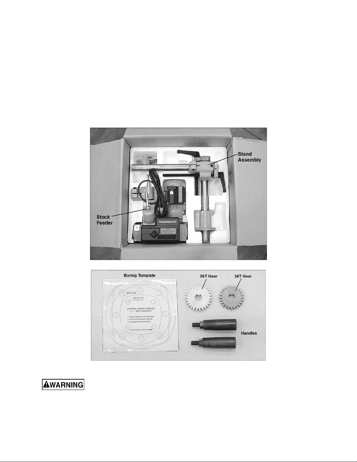
Unpacking
Open shipping cont ainer and check f or shipping
damage. Report any damage immediately to
your distributor and shipping agent. Do not
discard any shipping material until the Stock
Feeder is assembled and r unning properly.
Compare the c ontent s of y our cont ainer wit h t he
following parts list to make sure all parts are
intact. Mi ssing parts, if any, should be reported
to your distributor. Read the instruction manual
thoroughly for assembly, maintenance and
safety instructions.
Contents of the Shipping Conta iner
1 Stock Feeder
1 Stand Assembly
2 Handles
1 26-Tooth Gear
1 24-Tooth Gear
1 Boring Template
1 Owner's Manual
1 Warranty Card
Read and understand the entire contents of this manual before attempting set-up
or operation! Failure t o co mply may cause serious injury.
8
Page 9

Assembly and Installation
Tools needed for assembly:
5mm hex wrench
12mm and 14mm open end wrenches
Remove the clear plastic from around the feeder
and stand.
Exposed metal surfaces have been given a
protectiv e coating at the fact ory. This should be
removed wit h a soft cloth moistened with a good
commercial solvent, such as kerosene or
mineral spirits. Do not use acet one, gasoli ne, or
lacquer thinner for this purpose. Do not get
solvents near pl asti c or rubb er par ts, and d o not
use an abrasive pad because it may scratch
metal surfaces.
The Stock Feeder should be mounted to an
auxiliary machine in a well-lit area. Leave
enough space around the work area for l oading
and off-loadi ng stoc k and gener al maintenance.
The stock feeder and the
auxiliary machine to which you are mounting
it should both be disconnected from power
during insta llation.
1. Determine the mounting location for the
stand. Keep in mind t he overall l engt h of the
horizontal arm on the stand ( 27-1/2” ) so that
there will be enough adjustment when the
Stock Feeder is mounted.
IMPORTANT: Locate the stand so that you
will not drill through any ribs or supports
beneath the tabl e surface.
2. Use the provided boring template to find t he
centerline spacing for the holes in the
feeder’s base. Cl ean the mounting surface,
then remove the backing from the boring
template and stick the template carefully
into place on the mounti ng surface.
NOTE: The sam e template can be found on
page 25.
3. Center punch and drill four 8.5 millimeter
diameter holes in the surface, then tap the
holes with M10 x P 1.5 threads. Alter natively,
if you plan to secur e the stand wit h hex nuts
from below the mounting surface, drill
clearance holes of 7/16” diameter without
tapping.
4. Peel off the bori ng template and discard.
5. Loosen the lock handle and remove the
base from the stand assembly, shown in
Figure 1.
Figure 1
9
Page 10

6. Place the base ov er the hole patt ern. Align
the four hol es of the base with the hol es in
the mounting surface. Make sure the lock
handle is positioned in a convenient place
before tightening the base to the m ounting
surface.
7. Insert four M10 screws (not provided)
through the holes of the base and into the
holes on the mounting surface. See Figure
2. Tighten screws securely .
8. The stand assembly can be oriented with
either of the col umns in horiz ontal or verti cal
position. It is recommended, however, that
the longer lead screw be placed in the
horizontal position, as shown in Figure 3;
this will allow maximum adjustment for the
stock feeder across the surface of the
workpiece. Slide the vertical column down
into the base and tighten the lock handle
(Figure 3).
9. Attach a handle (Figure 4) to each elevati ng
handle, by screwing the threads of the
handle into the hole on the elevating handle.
10. The handle (F igure 4) should be a djusted so
that it can move freely. Loosen the hex nut
with a 14mm (9/16”) wrench, and turn the
socket head cap screw with a 5mm hex
wrench until the handl e is just loose enough
to turn freely. Then tighten the hex nut
against the el ev ating handle.
Figure 2
Figure 3
11. Rest the Stock Feeder on the mounting
surface, as shown in Figure 5. Lower the
horizontal arm by rotating the top hand
wheel until t he arm is at a conv eni ent height
for mounti ng the Stock F eeder. (See “Basic
Feeder/Stand Movements” for detailed
explanati on of stand m ov em ents.)
12. Make sure t he hex cap screw (A, F igure 5)
is loosened on the sleeve of the Stock
Feeder. Use a 14mm wrench.
13. Slide the arm cone of the Stock F eeder onto
the horizontal arm as far as it will go, then
tighten the hex c ap screw (A, Figure 5).
Figure 4
Figure 5
10
Page 11

Grounding Instructions
Electrical connections must
be made by a qualified electrician in
compliance with all relevant codes. This
machine must be properly grounded to help
prevent electrical shock and possible fatal
injury.
This Stock Feeder must be grounded. In the
event of a m alfuncti on or breakdown, grounding
provides a path of least resistance for electric
current to reduce t he risk of electric shock. This
tool is equipped wit h an electric cord having an
equipment-grounding conductor and a
grounding plug similar to the one shown in
Figure 6. The plug must be plugged into a
matching outlet that is properly installed and
grounded in accordanc e wit h al l loc al codes and
ordinances.
Do not modify the pl ug provided. If it will not fit
the outlet, hav e the proper outlet install ed by a
qualified elec trician.
Improper connection of the equipmentgrounding conductor can result in a risk of
electric shock. The conductor, with insulation
having an outer surface that is green with or
without yellow stripes, is the equipmentgrounding conduct or. If repai r or replac ement of
the electric cord or plug is necessary, do not
connect the equipment-grounding conductor to a
live terminal.
Check with a qualified electrician or service
personnel if the grounding instructions are not
completely understood, or if in doubt as to
whether the tool i s properly grounded. Us e only
three wire extensi on c or ds that have three-prong
grounding plugs and three- pole recept acles that
accept the tool ’s pl ug.
Repair or replace a damaged or worn cord
immediately.
115 Volt Operation
Figure 6
As received fr om the factory, your Stock Feeder
is ready to run at 115 volt operation. It is
intended for use on a circuit that has an outlet
and a plug that looks similar to the one
illustrated in Figure 6.
A temporary adapter, which looks like the
adapter as illustr ated in Figure 7, may be used
to connect t his plug to a two-pole recept acle, as
shown in Figure 7, if a properly grounded outl et
is not available. The temporary adapter should
only be used until a properly grounded outlet
can be installed by a qualified electrician. This
adapter is not applicable in Canada.
Figure 7
11
Page 12

The green colored rigid ear, lug, or tab,
extending fr om the adapter, must be connected
to a permanent ground such as a properly
grounded outlet box, as shown in Figure 7.
Make sure the voltage of your power supply
matches the specif ications on the m otor plate of
the machine.
Extens ion Cords
If an ext ension c ord i s necessary m ak e sure t he
cord rating i s suitable for the am perage listed on
the machine's motor plate. An undersize cord
will cause a drop in line voltage resulting in loss
of power and overheating.
Recommended Gauges (AWG ) of Extension Cords
Extension Cord Length *
25
50
75
100
150
200
feet
feet
feet
feet
feet
Amps
< 5 16 16 16 14 12 12
5 to 8 16 16 14 12 10 NR
8 to 12 14 14 12 10 NR NR
12 to 15 12 12 10 10 NR NR
15 to 20 10 10 10 NR NR NR
21 to 30 10 NR NR NR NR NR
feet
The chart in Figure 8 shows the correct size
cord to use based on cord length and motor
plate amp rating. If in doubt, use the next
heavier gauge. The smaller the gauge number
the heavier the cor d.
Adjustments
Basic Feeder/Stand Movements
To move the v ertical colum n up or down, l oosen
the lock handle (A, Figure 9) and rotate the
handle (B, Figure 9). When adjustment is
complete, re- tighten lock handle (A, Fi gur e 9).
To move the horizontal arm forward or back,
loosen the lock handle (C, Figure 9) and rotate
the handle (D, Figure 9). When adjustment is
complete, re- tighten lock handle (C, Figur e 9).
The vertical column and horizontal arm have
stop screws (E, Figure 9) which prevent them
from being moved t oo far.
To rotate the enti re stand assembly, loosen the
lock handle (F, Figur e 9) and pus h the assembly
into desired posi tion. Tighten l ock handle befor e
operating the st oc k feeder.
To rotate the stock feeder alone, loosen lock
handle (G, Fi gure 9) . Tighten l ock handl e before
operating the st oc k feeder.
*based on li miting th e lin e voltag e drop to 5V at 150% of th e
rated amp eres.
NR: Not Recomm ended.
Figure 8
Figure 9
Edgewise Stock Feeder Position
The stock feeder can be turned “edgewise” so
that the f eed is al ong the side of the workpiece.
See Figure 10.
To create thi s positi on:
1. Loosen the screw on the arm cone (A,
Figure 10) with a 14mm wrench, and slide
the Stock Feeder off the horizontal arm.
2. Place the Stock Feeder edgewise with the
rollers toward the bottom, as shown in
Figure 10.
Figure 10
12
Page 13

3. Loosen lock handle (B, Figure 10) and
rotate the swivel cone (C, Figure 10) 180degrees, as shown in Fi gur e 10.
4. Re-tighten l oc k handl e ( B, Figure 10).
5. Loosen lock handle (D, Figure 10) and
rotate the arm cone as needed until it can
slide back onto the horizontal arm. Tighten
locking handl e ( D, Fi gur e 10).
6. Mount the Stock Feeder to the horizontal
arm and tighten t he screw (A, Figure 10).
Speed Selection
The PF3-JR has f our speeds: 13, 26, 33 and 62
feet per mi nute (or 4, 8, 10 and 19 meter s per
minute, respectively). Achieving these four
speeds is dependent upon the choice and
proper positi on of t he gear s.
Unplug the stock f eeder fro m
power source before ch ang ing gears.
To change the positi on of t he gear s:
Figure 11
1. Unscrew the knob (Figure 11) and pull off
the back cov er to expose the gear system,
shown in Figure 12.
2. Remove hex nuts and flat washers (A,
Figure 12) with a 14mm wrench.
3. Figure 13 shows the relationship of gear
position t o c r eate each of the four speeds. A
similiar chart is affixed to the inside of the
back cover on the Stoc k Feeder .
4. Install new gear configuration, making sure
the notch in each gear slides into the
keyway of the shaft. Push the gear as far as
it will go onto the shaft .
5. Install hex nut and flat washer (A, Figure 12)
on each shaft, and tighten.
6. Re-install back cover and tighten knob
(Figure 11).
Figure 12
Figure 13
13
Page 14

Operating Controls
The control switch (Figure 14) turns the motor
on, and also determines its direction – forward
or reverse.
If a jam should occur while
feeding a w orkpiece, DO NOT turn the sto ck
feeder to reverse w hi le th e auxi liary mach in e
is still running in forward direction.
If a workpiece becomes jammed, turn off both
the auxiliary machine and the stock feeder.
Raise the feeder in order t o clear t he workpi ece.
Then reset the feeder height and begin t he feed
over again.
Figure 14
Operation
IMPORTANT: Before attempting operation of
this stock f eeder in c onjunction wit h an auxi liary
machine, you shoul d be thoroughly f amiliar with
the operating and safety instructions that were
included with the auxiliary machine.
Keep hands away from
rollers during operation. Failure to comply
may cause injury.
General Operating Instructions
1. Make sure all l ock handles are tight bef ore
operating the St oc k Feeder.
2. The Stock Feeder should be used in
conjunction with a fence on your auxiliary
machine.
3. The rollers must gri p the offcut, as well as
the part of the workpi ec e still being fed.
4. On some machines, such as a shaper, the
stock feeder can be mounted so that the
rollers exert pressure from the top; or
mounted edgewise so that the rollers exert
pressure from the side, or mounted at an
intermediate angle for beveled workpiec es.
5. The feed rollers have a spring suspension
with approximately 12mm lift, which will
exert the necessary pressure against the
workpiece. This pressure increases
automatic ally with feed r esistance, so that a
workpiece of varying thickness can be fed
through the stock feeder without
adjustments.
14
Page 15
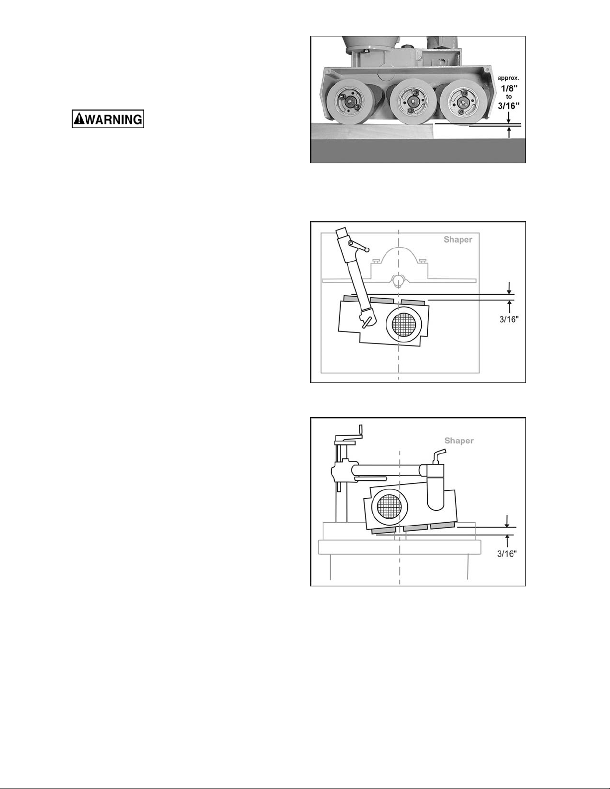
6. When used in normal horizontal position,
the stock feeder should be adjusted for
height so that the distance between the
table and the feed rollers is approximately
1/8” to 3/16” (3 to 5mm) less than the
thickness of the workpi ec e. See Figure 15.
Although the stock feeder
when properly used will greatly reduce the
chance of wo rkpiece kickb ack, t here i s still a
potential for kickback. Never stand directly
in the path of the workpiece as it passes
under the Stock Feed er rollers.
When Used with a Shaper
1. The gap between the fences for the cutter
should be as small as possible.
2. To ensure that the workpiece is held firmly
against the f ence, set the stock f eeder at a
slight angl e toward the f ence i n the dir ecti on
of feed. In other words, the outfeed roller
should be approxim at ely 3/16” (5mm) cl oser
to the fence than the infeed roller. See
Figure 16.
Figure 15
3. When the Stock Feeder is in edgewise
position, it must be inclined slightly t owards
the work table in the direction of feed, to
ensure the workpi ece remains forced down
against the table. In other words, the
outfeed roll er should be a pprox im ately 3/16”
closer to the work table than the infeed
roller. S ee Figure 17.
4. When the Stock Feeder is in the edgewise
position, or angled for a beveled workpiece,
the axis of the cutter should be between the
outfeed roller and the center roller. See
Figure 17. The center roller should NOT be
directed toward the opening between the
fences, but should act directly against the
fence.
5. When mounting the Stock Feeder in
edgewise posi tion, keep in mi nd the spring
tension of t he roller s. The distance bet ween
the shaper fence and t he f eed roller s should
be approximately 1/8” to 3/16” (3 to 5mm)
less than the thickness of the workpiece
(refer to Figure 15) .
6. Shaping hardwood with the Stock Feeder
may increase the fricti on between workpiece
and table. Keep t he work tabl e rust-free and
smooth, by using paste wax or other
necessary means.
Figure 16
(Stock Feeder in horizontal position)
Figure 17
(Stock Feeder in edgewise position)
15
Page 16

When Used with a Table Saw
1. Position the Stock Feeder so that the axis of
the saw blade lines up between the center
roller and infeed roller. See Fi gure 18. This
will allow the Stock Feeder to grip t he offcut
of the workpiece as it leaves the blade.
2. Rotate the Stock Feeder so that the
direction of feed is angled sli ghtly toward the
fence by approx im ately 3/16” (5mm) ; that i s,
the outfeed roll er shoul d be sli ghtly cl oser to
the fence t han the infeed roll er. See Figure
18.
When Used with a Jointer
1. Mount the stock f eeder on a jointer so that
all rollers are over the outfeed table, as
shown in Figure 19.
2. The infeed roller should be approximately
3/16” away from the lip of t he outfeed table
at the cutter ar ea. See Figure 19.
3. Rotate the Stock Feeder so that the
direction of feed is angled sli ghtly toward the
fence by approx im ately 3/16” (5mm) ; that i s,
the outfeed roll er shoul d be sli ghtly cl oser to
the fence t han the infeed roll er. See Figure
19.
Figure 18
Figure 19
Roller Removal/Replacement
If more space is needed between rollers, for
example when f eeding a curved workpi ece, the
center roller can be removed from the Stock
Feeder. To remove the roller, loosen and
remove the t wo socket head ca p scre ws (Fi gure
20) with a 5mm hex wrench and pull the roller
off the shaft.
Maintenance
Before performing any
maintenance on the Stock Feeder,
disconnect its plug from the electrical
supply. Also disconnect the auxiliary
machine from the el ect rical supply. Failure t o
comply may cause seriou s injury.
If the power cord is worn, cut, or damaged in
any way, have it repl ac ed immediately.
The rubber rollers should be kept clean of
grease, sawdust and other debris. Use a soft
cloth with soap and water to wipe down the
rollers. DO NOT use a solvent on the rubber
rollers.
Figure 20
16
Page 17

The mating parts of the arm cone and swivel
cone should be kept clean. See Figure 21.
When disassembli ng any of the cones from t he
stock feeder, wipe off both mating parts with a
clean rag before re-assembling. NOTE: These
cones are subject t o high tor ques and it m ay be
necessary to periodically re-tighten the lock
handles until the cone surfaces become
securely seated.
Lubrication
Gearbox
The Stock Feeder i s shipped with oi l install ed in
the gearbox. Occasionally check the oil level
and add oil if nec essary. The oil level shoul d be
approxim ately 1-1/ 2” deep; that is, about 1” from
the rim of the hole. Completely drain and refill
the oil every 1,000 working hours, or every 6
months, wit h a good quality gear oil.
Figure 21
To change the oil:
1. Loosen t he screw (A, Fi gure 5) which holds
the feeder body t o the horiz ontal arm.
2. Carefully remove the feeder body from the
horizontal arm.
3. Unscrew and rem ov e the oil cap (i dentified
in Figure 22) and turn the feeder body
upside down to completely drain the oil.
(NOTE: Always dispose of used oil
properly.)
4. Turn feeder body right side up, and pour
new oil into the fill hole, until it is about 1”
from the rim.
5. Re-install the oil cap (Figure 22).
Rollers
Each of the three rollers has a grease fitting
(Figure 23) located in the hub center. Use a
grease gun to insert a good quality, all-purpose
grease into these fittings every 200 working
hours, or every 30 days.
Figure 22
Figure 23
17
Page 18

Chains
Lubricate t he drive chai ns (Figure 24) with good
quality all-purpose grease every 3 months, or
more frequently if needed.
Lead Screw s
Occasionall y apply a light coat of gr ease to the
lead screw of the vertical column, and to the
lead screw of the hori z ontal arm. See Figure 25.
Figure 24
Figure 25
18
Page 19

Troubleshooting
Trouble Probable Cause Remedy
Not connected t o power source. Check plug connection.
Fuse blown, or cir c uit break er tr ipped. Replace fuse, or reset ci r c uit break er.
Feeder will not start .
Cord damaged. Replace cord.
Starting capac itor bad. Replace starting capacitor.
Wrong gears instal led for the desired
Feed speed is not
suffic ien t; m a ch in e
has low power.
Workpiece jams while
feeding it beneat h
rollers.
Workpiece slips while
passing under rollers.
Rollers slip on
workpiece.
feed rate.
Extension cord too light or too long.
Low current fr om el ectri c al suppl y . Contact a qualified electrician.
Rollers too low. Raise feeder.
Rollers too high, no traction. Lower feeder.
Grease or debris on roll er s. Clean rollers.
Replacement Parts
Install corr ec t gears i n pr oper
positions. [ page 13]
Replace with adequat e si z e and
length cord. [ page 12]
Replacement par ts are li sted on the f ollowing page s. To order parts or reac h our servi ce depar tm ent, call
1-800-274-6848, Monday through Friday (see our website for business hours, www.powermatic.com).
Having the Model Number and Serial Number of your mac hine available when you cal l will allow us to
serve you quickly and accurately.
19
Page 20

Parts List: PF3-JR Stand Assembly
Index No. Part No . Description Size Qty
1 ............... PF3JR-101 ..............Base ...................................................................................................... 1
2 ............... TS-1550061 .............Flat Wash er ........................................................M8 .............................. 1
3 ............... PF3JR-103 ..............Lock Handle .......................................................................................... 1
4 ............... TS-1540061 .............Hex Nut ..............................................................M8 .............................. 1
5 ............... PF3JR-105 ..............Elevating Bracket................................................................................... 1
6 ............... TS-1550061 .............Flat Wash er ........................................................M8 .............................. 2
7 ............... PF3JR-107 ..............Lock Handle .......................................................................................... 2
8 ............... TS-1540061 .............Hex Nut ..............................................................M8 .............................. 4
9 ............... PF3JR-109 ..............Mod. Screw ........................................................................................... 2
10 ............. TS-2361081 .............Lock Washer ......................................................M8 .............................. 2
11 ............. PF3JR-111 ..............Arm Cone .............................................................................................. 1
12 ............. TS-2310162 .............Hex Nut ..............................................................M16x1.5P ................... 1
13 ............. PF3JR-113 ..............Lock Handle .......................................................................................... 1
14 ............. TS-1550071 .............Flat Washer ........................................................M10 ............................ 1
15 ............. TS-1491081 .............Hex Cap Screw ..................................................M 1 0 x50 ...................... 1
16 ............. PF3JR-116 ..............Handle................................................................................................... 2
17 ............. PF3JR-117 ..............Vertical Column ..................................................................................... 1
18 ............. PF3JR-118 ..............Horizontal Arm ....................................................................................... 1
19 ............. PF3JR-119 ..............Elevating Screw ..................................................................................... 1
20 ............. PF3JR-120 ..............Horizontal Screw ................................................................................... 1
21 ............. PF3JR-121 ..............Column Cap .......................................................................................... 1
22 ............. TS-1524031 .............Socket Set Screw ...............................................M8x12 ........................ 3
23 ............. PF3JR-123A ............Elevating Handle ................................................................................... 2
24 ............. PF3JR-124 ..............Pin......................................................................4x30 m m .................... 2
25 ............. PF3JR-125 ..............Swivel Cone .......................................................................................... 1
26 ............. TS-2310162 .............Hex Nut ..............................................................M16x1.5P ................... 1
27 ............. PF3JR-127 ..............Lock Handle .......................................................................................... 1
20
Page 21

Exploded View: PF3-JR Stand Assembly
21
Page 22

Parts List: PF3-JR Stock Feeder
Index No. Part No . Description Size Qty
1 ............... PF3JR-201 ..............Oil Cap .................................................................................................. 1
2 ............... PF3JR-202 ..............“O” Ring ................................................................................................ 1
3 ............... PF3JR-203 ..............Sprocket Case ....................................................................................... 3
4 ............... PF3JR-204 ..............S pring.................................................................................................... 3
5 ............... PF3JR-205 ..............Case Cover ........................................................................................... 3
6 ............... PF3JR-206 ..............Roller Supporter .................................................................................... 3
7 ............... PF3JR-207 ..............Sprocket ................................................................................................ 3
8 ............... PF3JR-208 ..............Snap Ring ..........................................................Ø 22 mm .................... 3
9 ............... TS-1551041 .............Lock Was h e r ......................................................M6 .............................. 6
10 ............. TS-1503061 .............Socket Head Cap Screw .....................................M6x25 ........................ 6
12 ............. PF3JR-212 ..............Chain (18S) ........................................................18S ............................ 3
13 ............. PF3JR-213 ..............Tube ...................................................................................................... 3
14 ............. PF3JR-214 ..............Snap Ring ..........................................................Ø 26 mm .................... 3
15 ............. PF3JR-215 ..............Sprocket Shaft Assembly ...................................................................... 2
16 ............. PF3JR-216 ..............Snap Ring ..........................................................Ø 15 mm .................... 2
17 ............. PF3JR-217 ..............Sprocket Shaft Assembly ....................................................................... 1
18 ............. TS-1550071 .............Flat Washer ........................................................M10 ............................ 1
19 ............. TS-1540071 .............Hex Nut ..............................................................M10 ............................ 1
20 ............. PF3JR-220 ..............Grease Fitting ........................................................................................ 3
21 ............. PF3JR-221 ..............Shaft ..................................................................................................... 3
22 ............. TS-2361081 .............Lock Washer ......................................................M8 .............................. 3
23 ............. TS-1540061 .............Hex Nut ..............................................................M8 .............................. 3
24 ............. PF3JR-224 ..............Frame .................................................................................................... 1
25 ............. PF3JR-225 ..............Bushing ................................................................................................. 1
26 ............. PF3JR-226 ..............Sprocket ................................................................................................ 2
27 ............. PF3JR-227 ..............Sprocket ................................................................................................ 2
28 ............. PF3JR-228
29 ............. PF3JR-229 ..............Chain (30S) ........................................................30S ............................ 1
30 ............. PF3JR-230 ..............Chain (22S) ........................................................22S ............................ 1
31 ............. PF3JR-231 ..............Worm Gea r Shaft................................................................................... 1
32 ............. TS-1550071 .............Flat Washer ........................................................M10 ............................ 1
33 ............. TS-1540071 .............Hex Nut ..............................................................M10 ............................ 1
34 ............. PF3JR-234 ..............Oil Seal ................................................................................................ 1
35 ............. PF3JR-235 ..............Bushing ................................................................................................. 1
36 ............. PF3JR-236 ..............Worm Gea r Cover ................................................................................. 1
37 ............. PF3JR-237 ..............Oil Seal ................................................................................................. 1
38 ............. TS-1502031 .............Socket Head Cap Screw .....................................M5x12 ........................ 4
39 ............. PF3JR-239 ..............Gear (16T)..........................................................16T............................. 1
40 ............. PF3JR-240 ..............Gear (34T)..........................................................34T............................. 1
41 ............. PF3JR-241 ..............Gear (26T)..........................................................26T............................. 1
42 ............. PF3JR-242 ..............Gear (24T)..........................................................24T............................. 1
43 ............. PF3JR-243 ..............“O” Ring ................................................................................................ 1
44 ............. PF3JR-244 ..............Motor ..................................................................1/4HP, 1Ph, 115V ....... 1
................. PF3JR-244C ............Capacit or ( Not shown) ........................................250V 20uf ................... 1
45 ............. PF3JR-245 ..............Switch Box ............................................................................................ 1
46 ............. PF3JR-246 ..............Switch ................................................................................................... 1
47 ............. PF3JR-247 ..............Knob ..................................................................................................... 1
48 ............. PF3JR-248 ..............Back Cover ............................................................................................ 1
49 ............. PF3JR-249 ..............Roller (30 x 80 Dia) .............................................30x80 dia. mm ............ 3
50 ............. TS-1482041 .............Hex Cap Screw ..................................................M 6 x20 ........................ 2
51 ............. TS-1550041 .............Flat Washer ........................................................M6 .............................. 2
52 ............. PF3JR-252 ..............Powermatic Nameplate (not shown)....................1”x4” ........................... 1
53 ............. PF3JR-253 ..............Warning Label – Main Switch (not shown) ............................................. 1
..............Bushing ................................................................................................. 1
22
Page 23

Exploded View: PF3-JR Stock Feeder
23
Page 24

Electrical Connections for PF3-JR Stock Feeder
24
Page 25

Boring Template
SCALE 1:1
Cut out and tape int o plac e on mounting surface.
25
Page 26

NOTES
26
Page 27

27
Page 28

427 New Sanford Road
LaVergne, Tennessee 37086
Phone: 800-274-6848
www.powermatic.com
28
 Loading...