

Page 1
This .pdf document is bookmarked
Operating Instructions and Parts Manual
15-in ch Plan er
Models 15S and 15HH
WALTER MEIER (Manuf acturing), Inc.
427 New Sanford Road
LaVergne, Tennessee 37086, USA Part No. M- 0460286
Ph.: 800-274-6848 Revision E3 11/2010
www. powermatic. com Copyright © 2010 Walt er Meier (M anufacturi ng), I nc.
Page 2

W arranty and Service
Walter Meier (Manufacturing), Inc., warrants every product it sells. If one of our tools needs service or repair, one of our
Authorized Serv ice Cent ers located t hroughout t he U nited S t at es can give y ou quick se rv ice. In most cases, any of t hese Walter
M eier Authorized Service Cente rs can authorize w arranty repai r, assist y ou in obtaining parts, or p erform routine maintenance
and m ajor repair on your POWERM A TIC® tools. For the name of an Authorized Serv ice Center in y our area call 1-800-2 74-684 8.
MO RE INF ORM ATION
Walter Meier is consistently adding new products t o t he line. For complete, up-to-date product information, check with your local
Walter Meier distributor, or visit powerm a t ic.com .
WARRANTY
POWERMATIC products carry a limited w arranty which v aries in duration based upon the product.
WH AT IS CO VERED?
This warranty covers any defect s in workm anship or mat erials subject t o the except ions stat ed below . C utting tools, abrasives
and other consum ables are exc luded from warranty coverage.
WHO IS CO VERED?
This warranty covers only the initial purchase r of t he product.
WHAT IS THE PERIOD OF COVERAGE?
The general POWERMATIC warranty lasts f or t he time period specified in the product literat ure of each product .
WH AT IS NO T COVERED?
The Five Year Warranty does not cover products used f or commercial, industrial or edu cational purposes. Products w ith a Five
Year Warranty t hat are used f or comm ercial, indust r ial or education purposes revert to a One Year Warranty . Th is w arranty does
not cov er defects due directly or indirectly t o misuse, abuse, negligence or accidents, norm al w ear-and-tear, improper repai r or
alterations, or lack of maintenance.
HOW TO GET SERVICE
The product or part m ust be returned for exam ination, post age prepaid, to a locatio n designated by us. For the nam e of t he
location nearest y ou, please call 1-800- 274-68 48.
You m ust prov ide proof of in itial purchase date and an ex planation of t he com plaint m ust accom pany t he merchandise. If our
insp e c tio n d isclose s a d e fect, we will repai r o r re plac e the product, or refund t he purchase price, at our option.
We will return the re p aired p roduct or re plac ement at our expense unless it is determined by us that there is no defect, or that the
defect resu lted from ca u s es not with in the s c o pe o f our warr a n ty in wh ic h c a se we will, a t y o u r d irectio n , dispos e o f or ret u rn the
product. I n t he event you choose to have the product returned, you will b e responsible for the handling and shipping c osts of the
return.
HOW STATE LAW APPL IES
This warranty giv e s you specific legal rights; you may also have other rights which vary from st ate t o state.
LIMITATIONS ON THIS WARRANTY
WALTER MEIER (MANUFACTURING), INC., LIMITS ALL IMPLIED WARRANTIES TO THE PERIOD OF THE LIMITED
WARRANTY FOR EACH PRODUCT. EXCEPT AS STATED HEREIN, ANY IMPLIED WARRANTIES OR M ERCHANTABILITY
AND FITNESS ARE EXCLUDED. SOME STATES DO NOT ALLOW LIMITATIONS ON HOW LONG THE IMPLIED WARRANTY
LASTS, SO THE ABOVE LIMITATION M AY NOT APPLY TO YOU.
WALTER MEIER (MANUFAC TURING), INC., SHALL IN NO EVENT BE LIABLE FOR DEATH, IN JURIES TO PERSONS OR
PROPERTY, OR FO R INCIDENTAL, CONTINGENT, SPECIAL, OR CONSEQUENTIAL DAMAGES ARISING FROM THE USE
OF OUR PRODUCTS. SOME STATES DO NOT ALLOW THE EXCLUSION OR LIMITATION OF INCIDENTAL OR
CONSEQUENTIAL DAMAGES, SO THE ABOVE LIMITATION OR EXCLUSION MAY NOT APPLY TO YOU.
Walter Meier sel ls through distributors only . The specifications in Walter Meier catalogs are given as general info rmation and are
not binding. M embers of Walter M eier reserve t he right to effect at any time, without prior not ice, t hose alterations to pa rts,
fittings, and accessory equipment w hich they m ay deem necessary for any reason whatsoever.
2
Page 3

Table of Contents
Warranty and Service..........................................................................................................................2
Table of Contents ...............................................................................................................................3
Warn in g .............................................................................................................................................4
Fea ture s ............................................................................................................................................6
Spe cifi cation s .....................................................................................................................................6
Unpacking ..........................................................................................................................................7
Installation and Assembly ....................................................................................................................8
Handwheel......................................................................................................................................8
Starter Box......................................................................................................................................8
Extension Tables .............................................................................................................................9
Dust Hood.......................................................................................................................................9
Electrical Connect io ns .....................................................................................................................9
Extension Cords ............................................................................................................................ 10
Adju s tmen ts ..................................................................................................................................... 10
Belt Tension .................................................................................................................................. 10
Pulley Alignment ........................................................................................................................... 11
Table Rollers................................................................................................................................. 11
Cutterhead .................................................................................................................................... 12
Replacing Knives (M odel 15S only) ................................................................................................ 12
Replacing or Rotat ing Knife Inserts ( M odel 15HH only) .................................................................... 13
Work Table Parallel to Cutterhead .................................................................................................. 14
Know the Transmitti ng Rollers of Your Planer.................................................................................. 14
Anti-Kickback Fi nger s .................................................................................................................... 15
Infeed and Outfeed Roller Spri ng Tension ....................................................................................... 15
Height of Infeed Roller, Chipbreaker and Outf eed Rol ler .................................................................. 15
Outfeed Roller Heig ht .................................................................................................................... 16
Infeed Roller Height ....................................................................................................................... 16
Chipbreaker Height........................................................................................................................ 16
Chip Deflector ............................................................................................................................... 17
Feed Speed Control ...................................................................................................................... 17
Stock Retur n Rollers ...................................................................................................................... 17
Depth of Cut.................................................................................................................................. 18
Mai nten ance .................................................................................................................................... 18
Lubrication .................................................................................................................................... 18
Functio ns of the Digital Scale (Model 15S o nly) .................................................................................. 20
Troubleshooting: Performance Problems ............................................................................................ 23
Troubleshooting: Mechanical and Electrical Problems ......................................................................... 24
Troubleshooti ng: Digital Scale – Model 15S only................................................................................. 26
Switch Lock ...................................................................................................................................... 26
Optional Accessories ........................................................................................................................ 26
Replacement Parts ........................................................................................................................... 26
Head Assembly ............................................................................................................................. 27
Parts List: Head Assembly ............................................................................................................. 28
Base Assembly ............................................................................................................................. 30
Table Assembly............................................................................................................................. 32
Parts List: Table Assembly ............................................................................................................. 33
Gearbox Assembly ........................................................................................................................ 34
Parts List: Gearbox Assembly ........................................................................................................ 35
Cabinet Assembly ......................................................................................................................... 36
Parts List: Cabinet Assembly.......................................................................................................... 37
Electrical Connect io ns – Single Phase, 230 Volt ................................................................................. 38
3
Page 4

Warning
As with all machi nes, there is a cert ain amount of hazard involved wit h the use of t his planer . Use t he
machine with t he r es pect and caution demanded where safety pr ec autions are concerned. When normal
safety pr ecautions are overlooked or ignored, per s onal injury to t he operator c an result.
Read, underst and and f ol low the safety and operating instructions found in this manual. Know the
limitations a nd hazards associated with this machine.
Electrical grounding. Make certain that the machine frame is electrical ly gr ounded and t hat a ground
lead is included in the incoming electrical service. I n cases where a cor d and plug are used, make certain
that the grounding plug connects t o a suitable ground. Follow the grounding procedure indicated in the
National Electrical Code. I f connected t o a circ uit protected by fuses, use time delay fuse marked “D”.
Eye safety. W ear an approved safety shield, goggles, or glasses to protect eyes. (NOTE: Commo n
eyeglasses are only impact- r es istant, t hey are not safet y glasses. )
Personal protect i on. Bef or e oper at ing the machine, remove tie, r ings, wat c h and other jewelry and roll
up sleeves above the elbows. Remove all loose outer clot hi ng and co nfine long hair. Protective type
footwear should be used. Where the noise exceeds t he level of exposure allowed i n Section 1910.95 of
the OSHA Regulations, use hearing protective devices. Do not wear gloves.
Guards. Keep the machine guards in place for every operat ion for w hich they can be used. If any guards
are removed for maintenance, DO NOT OPER ATE the mac hi ne until the guards are reinsta lled.
Placement. Place machine so that pot ential kickback ar ea is not in line with aisles, doorways, wash
stations, or ot her wor k areas. Do not expose machine to rain or use in damp locations.
Work area. Keep the floor around the mac hi ne clean and free of scrap material, saw dust, oil and other
liquids to minimize the danger of tripping or slipping. Be sure the table is free of all scrap, f or eign material
and tools before star t ing to cut. Make certain the work area is well lighted and that a proper exhaust
system is used to minimize dust. It is recommended that anti-skid floor strips are used on the floor ar ea
where the operator normally stands a nd t hat each machine’s w or k ar ea be marked off. Provide adequate
work s pace around the machine.
Avoid acc idental star ting: Make c ertai n motor sw itch is in off positio n before co nnecti ng power to t he
machine.
Operat or position. M aintain a balanced sta nce and keep yo ur body under control at all times. Stand to
one side out of line with the table and make sure no one else is standi ng in line with the table.
Housekeeping. Before turning on machine, remove all extra equipme nt such as keys, w r enches, scrap,
and cleaning rags away f r om the machine
Careless acts. Give the wor k you are doing your undivided attentio n. Looki ng aro und, carr ying on a
conversation, a nd “horseplay” ar e car eless act s that can result in serious injury.
Disconnect machin e bef or e per f or ming any service or maintenance or w hen changing blades. A
machine under repair should be RED TAGGED to show it should not be used until the mainte nance is
complete.
Maintain tools in top condition. Keep tools sharp and clean for saf e and best per f ormance. Dull tools
increase noise levels and can cause kickbacks and gla zed s urfaces. Check the condition and adjustment
of the tools befor e making any cuts. Follow t he sharpening instructi ons on knife gr indi ng and jointi ng,
installi ng and adjustments.
4
Page 5

Hand safety. Keep hands outside the mac hine. NEVER reach under t he guards to t r y to clear stock that
stops f eeding. Do not clear chips and sawdust with hands; use a brush. Do not have any part of t he
hands under that part of the board that is over the table when starting a cut; the infeed roll will engage the
board and force it dow n against the table causing a pinching action. Do not operat e machine while the
gear cover is open.
Cutterhead rotation: Be sure cutterhead rotates under power in a co unterclockwise direction w hen
viewed fr om the main drive motor side.
Mater ial conditi on: Do not p lane boards wit h loose knots or w ith nails or a ny foreign mater ial o n its
surface. Knife impact o n these objects can cause the knives to be pulled out a nd cause them to shatter
against the chipbreaker or pres sure bar. Twist ed, warped, or in wind stock should first be joi nted on one
surface before attempting to plane a parallel surface on the planer. Serious stock flaws cannot be
removed by use of a planer alone.
Machine adjustme nt s: M ake all machine adjustments with power off except feed rate.
Avoid kickback: To avoid kickbacks, use this machine for single board surfacing only. Never make cuts
deeper than 1/8 inch (3mm).
Job completion. If the operator leaves the machine area for any reason, the planer should be turned
"off" and the cutterhead sho uld come to a complete st op bef or e his departure. I n addition, if the operation
is complete, he should clean the planer a nd the work area. Never clean the planer with power "on" and
never use the hands to clear sawdust and debris; use a brush.
Replacement par t s. Use only Powermatic or fact or y authorized replace me nt part s and accessories;
otherwise the warr anty and guarantee is null and void.
Misuse. Do not use this Powermatic planer for ot her than its intended use. If used for other purposes,
Walter M eier (Manufacturi ng), I nc., disclai ms any real or implied w ar r anty and holds itself harmless f or
any injury or damage which may result f r om that use.
If you are not t horoughly familiar w ith the operatio n of planers, obt ain advice from your supervisor ,
instructor or ot her qualified person.
Drugs, alcohol, med icatio n. Do not operat e t his machine while under the influence of drugs, alco hol, or
any medication.
Health hazards. Some dust creat ed by power sanding, sawing, gri nding, drilli ng and ot her construction
activities contains chemicals known to cause cancer, birt h defects or other repr oductive harm. Some
examples of t hese chemicals are:
* Lead from lead-based paint.
* Cr y s talline silic a from bricks and cement and other masonry products.
* Arsenic and chromium from chemically-treated lumber.
Your risk fr om these exposures varies, dependi ng on how of t en you do this type of work. To reduce your
exposure to these chemicals, w or k in a well-ventilated area, and wor k w it h approved safety equipment,
such as those dust masks that are specifically designed to filter out microscopic particles.
Familiarize yours elf with the f ollow ing saf et y not ices used in t his manual:
This means that if precautions are not heeded, it may result i n minor injury and/or
possible machine damage.
This means that if precautions are not heeded, it may result i n serio us injury or possibly
even death.
5
Page 6
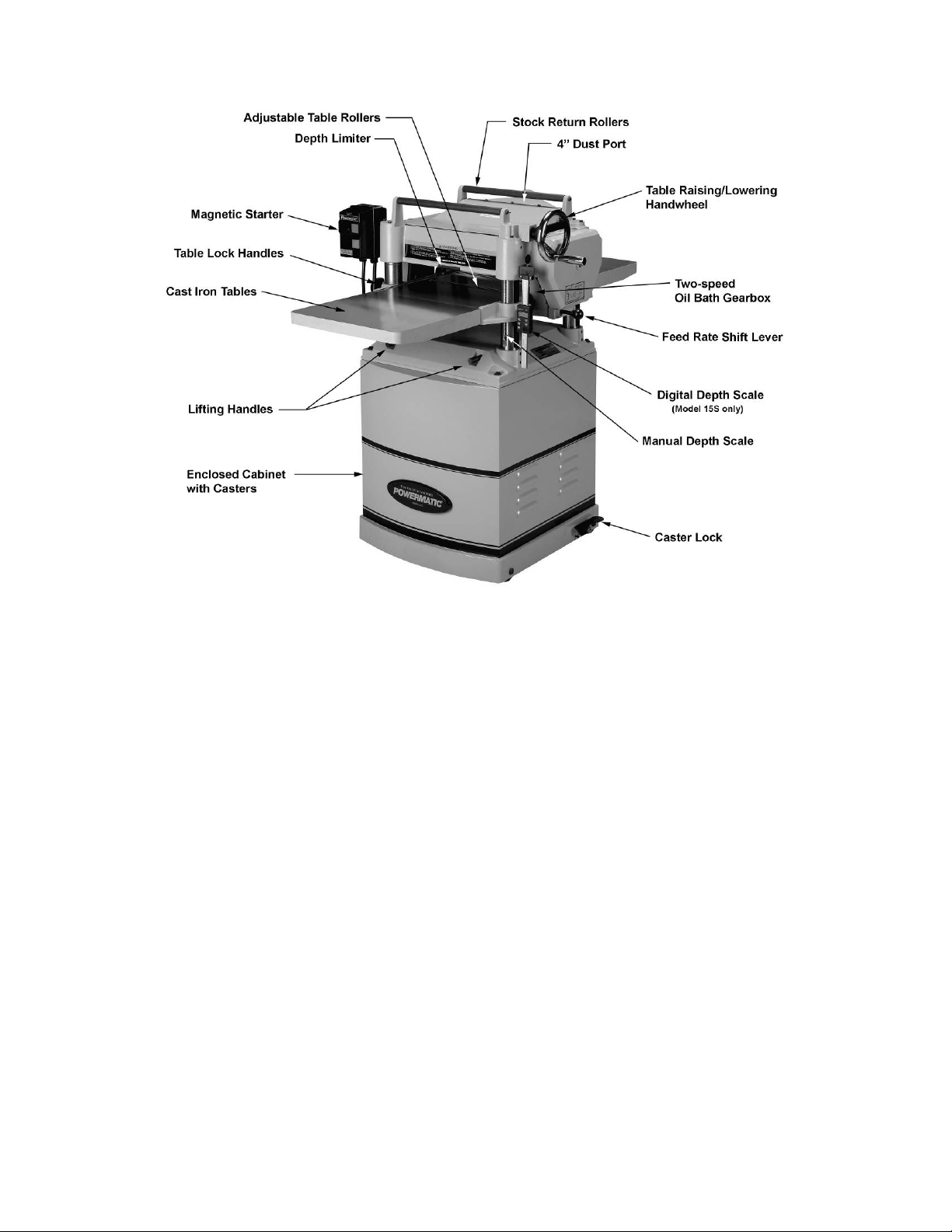
Features
Figure 1
Specifications
Model Number ........................................................................... 15S ........................................... 15HH
Stock Number .................................................................... 1791210 .......................................1791213
Maximum Cutting Width (in.)....................................................14-7/8 .......................................... 14-7/8
Maximum Cutting Thickness (in.) .................................................... 6 .................................................. 6
Full Width Cutting Depth (in.) ....................................................... 1/8 ............................................... 1/8
Minimum Planing Length (in.) ......................................................... 8 .................................................. 8
Minimum Stock Thickness (in.) ...................................................3/16 ............................................. 3/16
Knives........................................................................................... 3 ................... 74 four-sided ins er t s
Cutterhead Speed (RPM) ......................................................... 4,500 ........................................... 4,500
Cuts per Minute ..................................................................... 13,500 ............................... not applicable
Cutterhead Diameter ( in.) ......................................................... 2- 7 /8 ............................................ 2-7/8
Sound Rating @ 2” distance (dB).......................................... 82 to 85 ........................................80 to 84
Knife Insert Screw Max. Torque (pound force–inch) ......................----- ........................................45 to 55
Feed Rate (FPM) .............................................................. 16 and 20 ..................................... 16 and 20
Motor .................................................. TEFC, 3HP, 1Ph, 230V, 60Hz ....... TEFC, 3HP, 1Ph, 230V, 60Hz
Dust Chute Diameter (in.) ............................................................... 4 .................................................. 4
Overall Dimensions, Assembled (LxWxH)(in.) ............ 48 x 28 x 43-1/2 ............................ 48 x 28 x 43-1/2
Cabinet Footpri nt, incl uding foot pedal (LxW)( i n.) .............. 23-1/2 x 23 ................................... 23-1/2 x 23
Net Weight (lbs.) .........................................................................507 .............................................. 502
Shipping Weight (lbs.) .................................................................573 .............................................. 568
The above specificati ons were current at the time t his manual w as publis hed, but beca use of our policy of
continuo us impro vement, Walt er M eier ( M anufacturi ng) Inc., reserves the right to change s pecificat ions at
any time and without prior notice, w ithout i ncurri ng obligations.
6
Page 7
Unpacking
Open container a nd check for shipping damage.
Report any damage immediately to your
distributor and shipping agent. Do not discard
any shipping material until the Planer is
assembled a nd running properly.
Compare the contents of your co ntainer w ith the
following list to make sure all parts are intact.
Report any missing parts to your distributor.
Read this owner’s manual thoroughly for
assembly, maintenance and safety instructions.
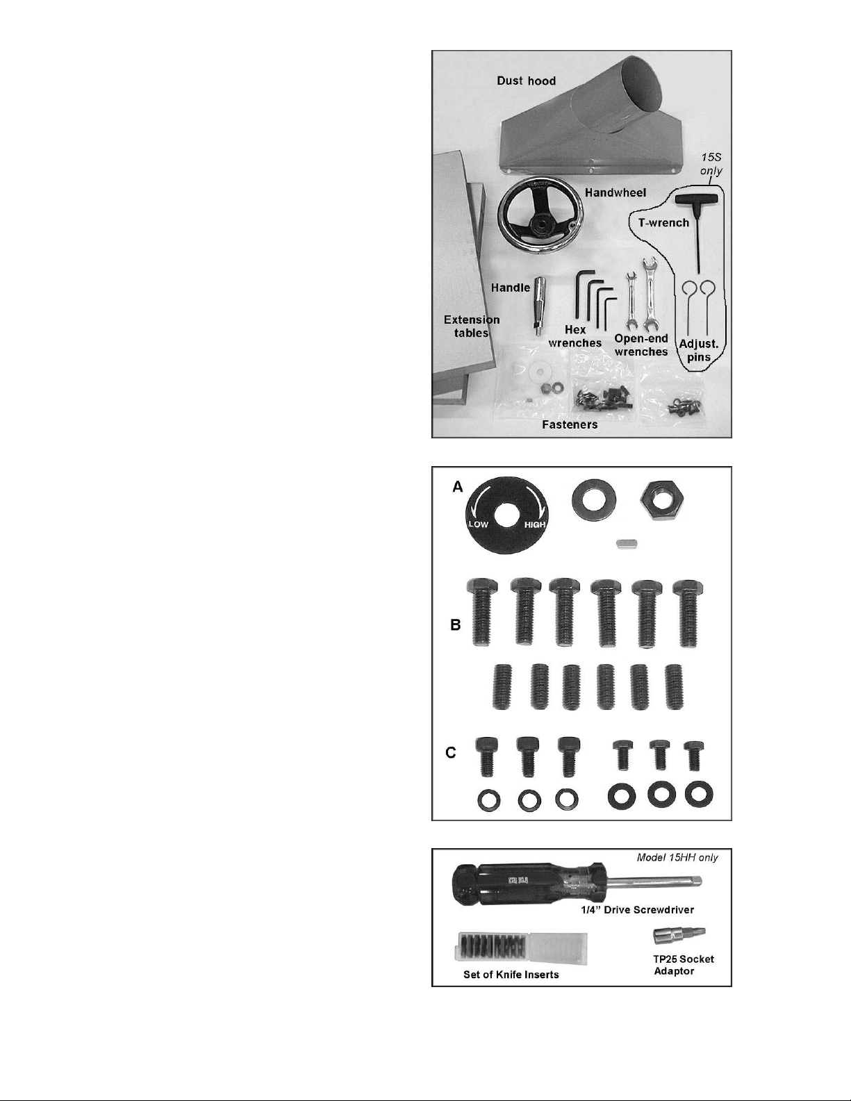
Crate Contents (Figure 2):
1 Planer (not shown)
1 Dust hood
2 Cast iron extension tables
1 Handwheel
1 Handle
4 Hex wrenches (3, 4, 5 and 6mm)*
2 Open-end wrenches (8-10, 12-14mm)*
3 Bags of fast eners* – see below
1 Owner’s manual (not show n)
1 Warranty card (not shown)
Model 15S onl y:
1 T-handl e hex wrench (4 m m )*
2 Adjustment pins*
Model 15HH ONLY (Fi gur e 4):
1 1/4” Drive Screwdr iver
1 T25P Torx Plus Drive Socket Adaptor
1 Set of 10 Knife Inserts
Contents of fastener bags* ( Fi gur e 3):
A – (for installing handwheel)
1 Direction label
1 Hex nut
1 Flat washer
1 Key
B – (for installing extension tables)
6 Hex cap screws, M 8x25
6 Socket set screws, M8x20
C – (for installing dust hood)
3 Socket head cap screws, M6x12
3 Lock washers, M6
3 Hex cap screws, M 5x10
3 Flat washers, M 5
*indicates part s included in hardw ar e kit 15S- HK
Figure 2
Figure 3
Figure 4
7
Page 8
Installation and Assembly
Tools required f or asse mbly:
Forklift or hoist with slings
10-12,12- 14mm open-e nd wrenches (provided)
4 and 5mm hex wrenches (provided)
16mm open-e nd wrench
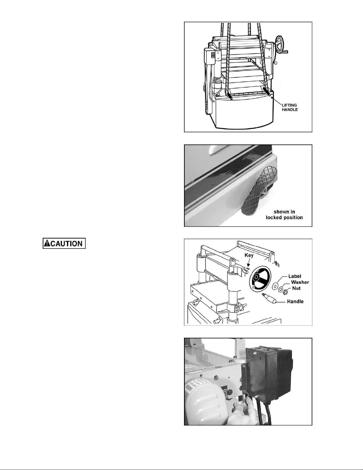
Remove the screws holding the planer to the
pallet and use a forklift or hoist to lift the planer
off t he pallet. Forks and straps should alw ays be
placed under t he four lifti ng handles when lifti ng
this machine (Fig ure 5). The lift ing handles can
be pushed back in when not in use.
The pla ner should b e operated i n a well- lit area
with good ventilation. It can be rolled on its
casters to the desired location. Press the foot
pedal (Figure 6) to prevent movement during
operation or adjustments.
Exposed surfaces, such as tables, rollers,
cutterhead, etc., have been given a protective
coating at the factory. This should be removed
with a soft cloth moistened with a good
commercial solvent. Do not use acetone,
gasoline, lacq uer thi nner, or other solvents with
a low flas h poi nt. Do not use an abras ive pad
because it may scratch the polished cast iron
surfaces.
Figure 5
Figure 6
Use care when cleaning
around the cutterhead area – knives are
extremely sharp!
Handwheel
1. Place the key into the slot on the shaft
(Figure 7), and mo unt the handw heel to t he
shaft, making sure it is oriented so it slips
over the key.
2. Peel off the backing of the directio nal label,
and attach it to t he center of the handwheel.
Place flat washer a nd hex nut o n s haft and
tighten with 16mm wrench.
3. Mount the handle i n t he t hreaded hole in the
handwheel, and tighte n with a 12mm wrenc h
placed over the flat on the handle.
Starter Box
Mount the controls as shown in Figure 8, with
the two socket head cap screw s w hich yo u’ll find
mounted to the head casting. Use a 5mm hex
wrench.
Figure 7
Figure 8
8
Page 9
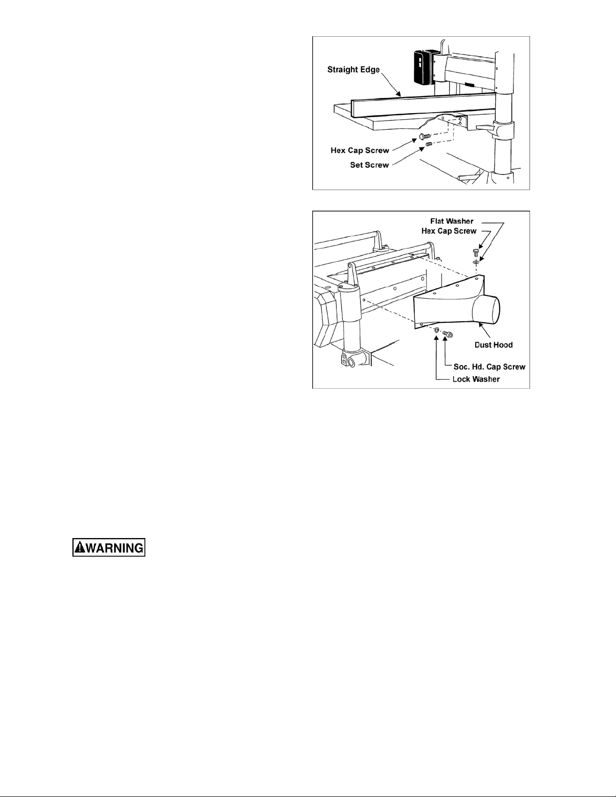
Extension Tables
1. Mount a cast iron table to the edge of the
main table with three M8 x 25 hex cap
screw s ( Figure 9) using a 12mm wrench. Do
not fully tighten yet.
2. The extensio n table must be le veled w ith t he
main table. P lace a straig ht edge (suc h as a
jointed board) across the extension table
and the main table.
NOTE: T he straig ht edge should not lie over
the raised t able rollers, as t his wo uld distort
the leveling process. Either place the
straight edge just short of t he table rollers, or
lower the table rollers completely into the
table (see page 11) while mounting the
extension tables.
3. Insert three socket set screws with a 4mm
hex wrench, and screw them in or out as
needed until tables are level.
4. Securely tig hten the hex cap screw s .
5. Mount the second extension table to the
opposite side of the pla ner table, usi ng t he
same procedure.
Figure 9
Dust Hood
Mount the dust hood to the rear of the head
casting with three M6 x 12 socket head cap
screws with lock washers, and three M5 x 10
hex cap screws with flat washers. See Figure
10.
It is recommended that you use a dust collection
system with this planer. If you are not using a
dust collection system, do not attach the dust
hood to the planer, as t he accumulation of dust
inside the hood may create a safet y hazard, or
eventually cause jammi ng of the rollers.
Elect ri cal Connectio ns
Electrical connections must
be made by a qualified electrician in
compliance with all relevant codes. The
machine must be prop erly grounded t o help
prevent electrical shock and possible fatal
injury.
A power plug is not provided with the 15S or
15HH planers. You may either connect a 230
volt plug or "hard-wire" the machine directly to
your electrical panel provided there is a
disconnect near the machine. Consult electrical
schematic on page 38 f or further clarification of
wiring setup.
Figure 10
It is r ecommended that the 15S or 15 HH Planer
be connected t o a dedicated, minimum 40 amp
circuit with a 40 amp circuit breaker or time
delay f use. Loc al codes take precedence over
recommendations.
9
Page 10
This machine must be grounded. Grounding
provides a path of least res istance to help d ivert
current away from the operator in case of
electrical malfunct ion.
Make sure the voltage of your power supply
matches the specificat ions on the motor plate of
the machine.
Extension Cords
The use of an extension cord is not
recommended for this machine, but if one is
necessary make sure the cord rating is suitable
for t he amperage listed on the machine's motor
plate. An undersize cord will cause a drop in line
voltage resulting in loss of power and
overheating.
The chart in Figure 11 shows the correct size
cord to use based on cord length and motor
plate amp rating. If in doubt, use the next
heavier gauge. The smaller the gauge number
the heavier the cord.
Recommended Gauges (AWG) of Extension Cords
Extension Cord Length *
25
50
75
100
150
200
Amps
< 5 16 16 16 14 12 12
5 to 8 16 16 14 12 10 NR
8 to 12 14 14 12 10 NR NR
12 to 15 12 12 10 10 NR NR
15 to 20 10 10 10 NR NR NR
21 to 30 10 NR NR NR NR NR
*based on limiting the line voltage drop to 5V at 150% of the
rated am per es.
NR: Not Recommended.
feet
feet
feet
feet
feet
feet
Figure 11
Adjustments
Tools required f or asse mbly:
10, 12 and 17mm open-end wrenches
3, 5 and 6mm hex wrenc hes
0.2” ( 0.5mm) feeler gauge
straight edge
gauge block
cross-point screwdriver
Disconnect machine from
power source before making any
adjustments ( except f eed r at e) .
Belt Tension
Inspect the tension of the belts fr equently duri ng
the first few times you use the planer. Belts often
stretch during this trial period. If they require
tightening, pr oceed as follows:
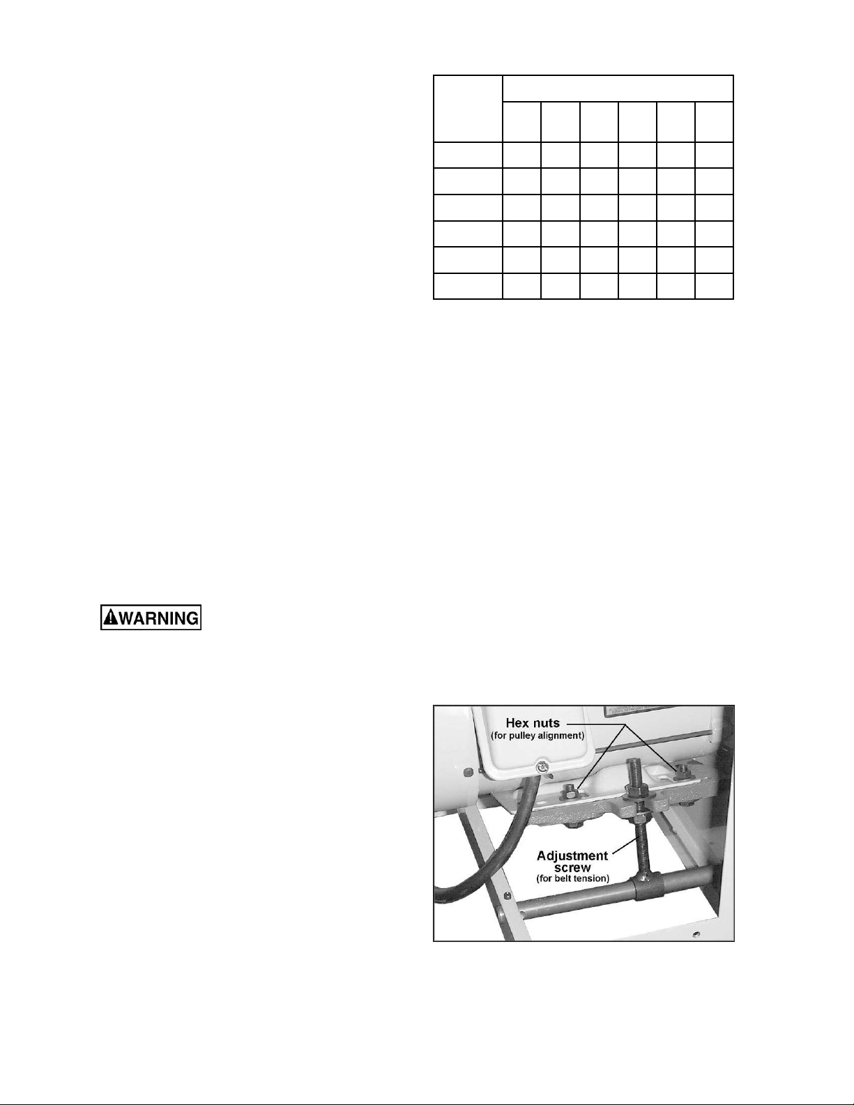
1. Remove the belt guard and the rear panel.
2. Loosen the bottom nut on the motor
adjustment screw (Figure 12) with a 17mm
wrench.
3. Tur n the top nut on t he adjust ment scr ew t o
lower the motor plate, which will increase
the belt tension.
4. Proper tension is achieved when there is
slight deflectio n in the belt midway between
the pulleys, using moderate f inger pr ess ure.
5. Tighten the bottom nut on the adjustment
screw (Figu re 12).
Figure 12
10
Page 11
Pulley Alignment
The pulleys should be in line for proper belt
operation.
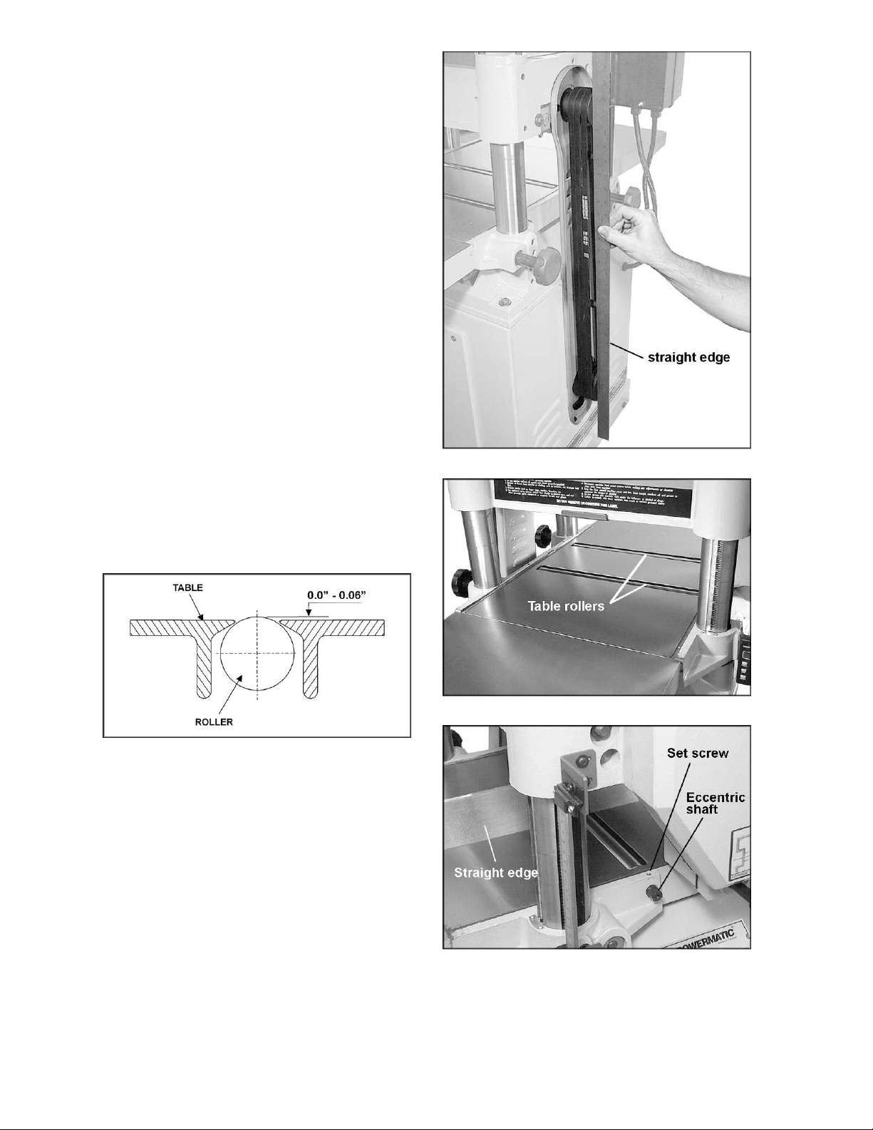
1. Remove the belt g uard a nd place a s traig ht
edge against the faces of both pulleys
(Figure 13).
2. If the straight edge does not lie flat on both
pulley faces, open the rear panel and loose n
the four hex nuts on the motor plate (see
Figure 12) w ith a 12mm wrench.
3. Nudge t he motor left or r ight until the pulleys
are in alignment.
4. Tighte n hex nuts and replace covers.
Tab le Roll ers
Your planer is supplied with two table rollers
(Figure 14) which turn as the stock is fed into the
machine, thus reducing friction. It is not possible
to give exact dimensions on the proper height
setting of t he table rollers beca use eac h type of
wood behaves differently. As a general rule,
however, when planing rough stock the table
rollers should be set at high position. When
planing smoot h stock the rollers should b e set at
low po s ition.
Figure 13
NOTE: When raisi ng the roller higher abo ve the
table, t he range is from zero to 0.06" (Figure 15).
Figure 15
The table rollers are factory set for average
planing and are parallel to the table surface. If
you desire to adjust the table rollers higher or
lower, pr oceed as follows:
1. Disconnect machi ne from pow er source.
2. Lay a str aight edge across bot h rollers.
3. On one side of the table, loosen the set
screw s (Figure 16) with a 3mm hex wrench,
and turn the eccentric shafts to raise or
lower the rollers.
4. When pr oper height is ac hie ved, tighte n set
screws.
Figure 14
Figure 16
5. Adjust the rollers from the opposite side of
the table in the same manner.
11
Page 12
IMPORTANT: Be sure that the height of front
and rear rollers are the same. And the table
rollers must always be set parallel to the table.
Cutterhead
Although your planer was carefully adjusted at
the factory, it should be checked before being
put into operation. Any inaccuracies due to
rough handling in transit can be corrected by
following the directions in t his manual.
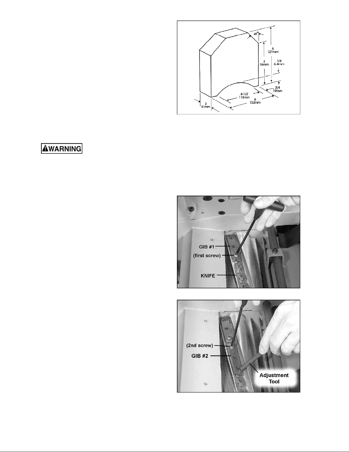
To check the adjustments yo u will need feeler
gauges, and a di al gauge or home-made ga uge
block made of hardwood. This ga uge block can
be made by fo llowing the di me nsio ns s hown in
Figure 17.
Repl aci ng Knives (Model 15S only)
Figure 17
Use caution and proceed
slowly when working with and around the
knives – they are extremely sharp!
When dull knives are replaced, care must be
exercised in setting the new knives into the
cutterhead. There is a certain procedure to
follow which will ensure a proper setting of
knives on the 15S Planer. Proceed as f ollows:
1. Disconnect machi ne from pow er source.
2. Remove the dust hood and the top cover.
Remove the chip deflector (Figure 28 s how s
the chip deflector). Remove the belt g uard
so you can rotate the cutterhead using t he
pulley.
3. Remove the gib screws with the T-handle
hex wrench, as shown in Figure 18, and
remove each gib one at a time.
4. Carefully remove the knife, and clean the
cutterhead slot of any dust or debris.
5. Place the new knife into the cutterhead slot.
6. IMPORTANT: As you proceed with knife
installation, make sure the wings on both
ends of each hole (see Figure 18) are
completely inserted into the groove in the
cutterhead. Failure to do this may result in
knife breakage during operatio n.
Figure 18 – Model 15S onl y
7. There are a total of three short gibs and
twelve long gibs on the cutter head. It is not
important w het her long or short gib is used
in any particular location along the knife. Of
course, eac h knife must use one short gib.
8. Put the first gib in place at the end of the
cutterhead. Use the knife adjustment pins
shown in Figure 19. The adjust ment pins fit
down through the smaller holes in the gib,
knife, and cutterhead, helpi ng to align t hem.
Figure 19 – Model 15S onl y
12
Page 13

(
You can also us e any 3mm diameter tool,
such as a hex wrench or drill bit for this
purpose.)
9. Insert the screws for the first gib, turning
them with t he T-handle wr ench. Do not fully
tighten the screws; make them only snug
enough to hold the knife in the groove.
10. Put the next gib in place, and repeat the
process. See Figure 19. Use t he adjustment
pins and make sure t he wings of t he knife
are completely in the cutterhead groove.
Continue sequentially from one end of the
cutterhead to the other end. Again, only
make the screws snug enough to hold the
knife in the groove.
11. When all gibs are loosely installed for one
knife, rotate the cutterhead and repeat t he
process for each of the remaining two
knives, wor k ing from one end to the other.
12. Now f ully tig hte n all gib screw s on one knife.
Do this i n seq uent ial order, begi nning at one
end of the knife and working your way
across to the other end, tightening each
screw in turn.
13. Tighten all gib screws on the other two
knives in the same fashion, until all gib
screws on the cutterhead are firmly
tightened.
(NOTE: The purpose of this incremental
tightening process is to prevent any slight
deflectio n or war page of the c utter head, and
to ensure that the knife is completely seated
into the groove.)
After install ing knives, c heck
again carefully. Make certa in all gib screws
are tightened securely. Failure to h eed may
res u lt in personal in ju r y .
14. Re-install chip deflector (see “Chip
Deflector”, page 17). Re-install cover with
the four was her head screw s, and re-install
belt guard.
Figure 20 – Model 15HH onl y
Each knife insert has an etched reference mark
so you can keep track of the rotat ions.
IMPORTANT: When removing or rotating
inserts, clean saw dust from the screw, the
insert, and the cutterhead platform. Dust
accumulation between these elements can
prevent the insert from seating properly, and
may affect the quality of the cut.
Before installing each screw, lightly coat the
screw threads w ith machine oil and wipe off any
excess.
Securely tighten each screw which holds the
knife inserts before operating the planer.
IMPORTANT: Maximum torque for tightening
the screws is 45 to 55 inch po unds (3. 75 to 4.6
foot pounds).
Make sure all knife insert
screws are tightened sec urely. Loose inserts
can be propelled at high speed from a
rotat ing cutt er head, causing in jury.
Repl aci ng or Rotating Knife Insert s (Model 15HH only)
The knife inserts on the model 15HH are foursided. When dull, simply remove each insert,
rotat e it 90° for a fresh edge, and re-install it.
Use the provided driver with the socket adaptor
to remo ve t he knife insert s cr ew . See Figure 20.
It is advisable to rotate all inserts at the same
time to maintain consistent cutting. However, if
one or mor e knife inserts develo ps a nick, rot at e
only those inserts that are af f ected.
13
Page 14

Wo rk Table Parallel t o Cu t t erhead
The work table is set par allel to the cutterhead at
the factory and no f urther ad justment s hould be
necessary. If your machine is planing a taper,
first check to see if t he knives are set pr oper ly i n
the cutterhead. Then check to see if the work
table is set parallel to the cutterhead. Proceed
as follows:
1. Disconnect machi ne from pow er source.
2. Place the gauge block (Figure 21) on the
work table directly under the edge of a knife
as shown. Make slight contact by gently
raising table.
3. Move the gauge block t o the opposite end of
the work table. NOTE: Distance from the
work table to edge of knife should be the
same.
4. If the work table is not parallel to the
cutterhead, perform the adjustment
procedure as follows.
5. Remove bolts holding the planer to the
stand. Carefully tilt planer on its side to
expose underside of base ( Figure 22).
Figure 21
6. Remove bolt (A, Figure 22) and loosen bolt
(B, Figure 22) whic h will a llow yo u to mo ve
the idler sprocket assembly (C, Figure 22)
far enough to release t ension on the chain.
7. Remove the chain from the particular
sprocket on the corner of the base that you
need to adjust.
8. Turn the sprocket by hand to bring that
corner into adjustment with the ot her three
corners. NOTE: Turning sprocket clockwise
will increase the distance between the
working table and the head casting;
counterclockwise will decrease t he distance.
This adjustment is very sensitive and it
should not be necessary to t urn the sprocket
more than one or two teeth.
9. When adjustments are correct, replace
chain around corner sprocket, slide idler
sprocket (C, Figure 22) back to re-tension
chain, tighten bolt (B, Figure 22) and insert
and tighten bolt (A, Figure 22).
Know the Transmitting Rollers of Your Planer
(Figure 23)
Figure 22
A. Anti-Kickback Fingers
B. Infeed Roller
C. Chipbreaker
D. Cutterhead
E. Outfeed Roller
Figure 23
14
Page 15

Anti-Kickback Fingers
The anti-kickback fingers (A, Figure 23) are an
important safety feature, as they help prevent
kickback of stock. They operate by gravity and
should be inspected frequently to make sure
they are free of gum and pitch, so that they
move independently a nd operate cor r ec t ly.
In f eed and Out f eed Roller Spring
Tension
The infeed roller (B, Figure 23) and outfeed
roller (E, Figure 23) are those parts of your
planer that feed the stock while it is being
planed. The infeed roller and the outfeed roller
are under spring tension and this tension must
be sufficie nt to feed t he st ock uniformly t hrough
the planer without slipping but should not be so
tight that it causes damage to the board. The
tension should be equal at both ends of each
roller.
To adjust the spring tension of the infeed and
outfeed rollers, turn screws (Figure 24) with a
hex wrench. Turn screws on both ends of
infeed/outfeed r ollers i n the same manner.
Figure 24
Heig ht of Inf eed Roller, Chipbreaker
and Ou t f eed Roll er
The infeed r oller, c hipbreaker a nd o utfeed roller
are adjusted at the factory. The height
relationship between these items and the
cutterhead is crucial for accurate and safe
planing. The infeed roller, chipbreaker, and
outfeed roller should each be set at 0.02"
(0.5mm) below the cutting circle. See Figure 25.
If any adjustments are necessary for the infeed
roller, chipbreaker , or outfeed r oller, they should
be done carefully. Use the followi ng steps as an
example of proc edure.
NOTE: This procedure uses a home-made
gauge block and feeler gauges, whic h should be
sufficient for most planer operations. If extra
precise measurements are desired, use a dial
indicator device.
Figure 25
15
Page 16

Outfeed Roll er Height
1. Disconnect machi ne from pow er source.
2. Make sure the knives are set properly as
previously explained under "Knife
Adjustment."
3. Place t he gauge block (F, Figure 26) o n the
table directly beneath the cutterhead (D,
Figure 26).
4. Using a 0.02" (0.5mm) feeler gauge (G,
Figure 26) plac ed on top of t he gauge block,
raise the work table until the knife just
touches the feeler gauge when the knife is
at its lowest point. Do not move the work
table any further until the outfeed roller is
adjusted.
5. Remove the feeler gauge and move the
gauge block ( F, Fig ure 27) under o ne end of
the outfeed roller. The bottom of the outfeed
roller s hould just to uch the top of t he ga uge
block. If an adj ustment t o the outfeed roller
is necessary, loosen the lock nut (J, Figure
27) and turn screw (H, Figure 27) until the
outfeed roller just t ouches t he ga uge block.
Then tighten lock nut (J, Figure 27).
Figure 26
6. Check and adjust the opposite end of the
outfeed roller in the same manner.
In f eed Roller Height
Use t he exact same pr oced ure for c hecking t he
infeed roller as you did for the outfeed roller.
Use the .02" (0.5mm) feeler gauge atop the
gauge block. If adjustment is necessary, use the
lock nut and screw on each end of t he infeed
roller.
Chi pbreaker Heig ht
The chipbreaker breaks off the larger chips
before the stock reaches the cutterhead. Use
the gauge block and a .02" (0.5mm) feeler
gauge to check the height of the chipbreaker,
following the same procedure as above. If
adjustment is needed:
1. Remove top cover.
2. Loosen the lock nuts (A, Figure 28) at bot h
ends of the chipbreaker, and turn the set
screw s to raise or low er the chipbreaker as
needed. The set screws should be turned
the same amount.
3. When the chipbreaker contacts the gauge
block, tighte n both lock nuts (A, Figure 28).
Figure 27
Figure 28
16
Page 17

Chi p Def lector
The chip def lect or ( B, Fig. 28) k eeps wood chips
from falling i nto t he outfeed r oller. The def lector
should be set approximately 1/16" to 1/8” from
the tip of the knives. Make sure the deflector is
oriented so the bevel on its fr ont edge matches
the shape of the cutterhead.
Feed S peed Con t rol
Your machi ne is equipped with a s piral, serrated
infeed roller and a solid steel outfeed roller.
When the feed ro llers are e ngaged, t hey turn to
feed the stock. The feed rollers slow
automatically w hen the machine is under heavy
load for best pla ning in all co ndit io ns. T he feed
rollers are dri ve n by c hains and sprockets ( see
Figure 29) which take power directly from the
cutterhead through the oil bath gear box. The
drive chain does not need tensioning, as a
tension device (Figure 29) maintains proper
tension at all times .
To gain access to the chain and sprockets:
1. Remove the handwheel from t he machine.
Figure 29
2. Remove the socket head cap screw f r om the
center of the cover, and remove the left
triangular back plat e. See Figure 30.
3. Pull the cover off the machine.
Always re-install cover over
the chain and sprockets before operating
planer.
The gear box has two feed speeds. These are
set by pulling out or pushing in the shift lever
(Figure 31). Always change feed speed while
the machine is running. A label showing the
lever positions is affi xed just above the lever. I t
is also shown in Figure 32.
Do not attempt to change
feed speed while stock is passing through
the machine. Damage to the gearbox may
result.
Sto ck Ret urn Rol lers
The two rollers on top the machine serve as a
convenient rest for stock. They save time and
motion for the operator as the stock is returned
to the infeed side.
Figure 30
Figure 31
Figure 32
17
Page 18

Depth of Cut
The cutting depth scale is a combination
inch/metric scale (Figure 33), with a cutting
range from 0 to 6" (152. 4mm). A manual scale is
mounted directly to t he front column. T he mod el
15S planer also features a digital scale for
easier, more precise dept h readings.
Periodically check all the chains for proper
tension and adjust accor dingly if required.
The table s hould be kept clean and fr ee of rust.
Some users prefer a paste wax on exposed
steel a nd cast iron surfaces. The w ax pro vides a
layer of protection as well as reducing friction
between lumber and the table, making cuts
faster and smoother. Avoid any wax that
contains silicone or ot her synthetic ingredients.
These materials can find their way into lumber
and can make staining and finishi ng diffic ult.
Another optio n is t alcum powder appl ied wit h a
blackboard eraser rubbed in vigorously once a
week; this will fill casting pores and form a
moisture barrier. This method provides a table
top that is s lick a nd allows rust ri ngs t o be easily
wiped fr om the surface. Important also is the fact
that talcum powder will not stain wood or mar
finishes as some wax pickup does.
Figure 33
The dista nce of upward or downward moveme nt
is controlled by the handwheel (Figure 33).
Before moving t he table up or down, loosen t he
locking handles (Figure 33). After obtaining
proper table position, tighten the locking
handles.
Maximum dept h of cut is 3/16". A limiter (Figure
33) on the front of the head casting limits the
depth of cut on full width planing under 1/8".
The digital scale should be calibrated before
operating the planer. Refer t o page 21.
Maintenance
Disconnect machine from
power source before performing any
maintenance.
Periodic or regular inspections are required to
ensure that the machine is in proper adjustment,
that all screws are tight, that belts are in good
condition, t hat dust has not accumulated i n t he
electrical enc los ures, and that t here are no worn
or loose electrical connections.
Lubrication
The bearings on the cutterhead are factory
lubricated a nd sealed for life – no l ubricatio n is
required.
Gearbox Lubr icant
The lubricant in the gear bo x must be replaced
every 2,500 hours. Multi-purpose gear box
lubr ic ant w ill b e s u itable.
To replace the lubricant:
1. Remove t he drain plug (A, Fig ure 34) with a
14mm wrench, and remove filler cap (BFigure 33). Dr ain dirty oil thoroughly.
2. Insert and tighten the drain plug (A, Figure
34).
3. Fill with clean lubricant through hole (B,
Figure 34).
4. I nstall a nd t ighten filler c a p (B, Fig ure 3 4).
Buildup of saw dust a nd ot her debris ca n cause
your machine to plane inaccurately. Periodic
cleaning is not only recommended but
mandatory for acc urate planing.
Close-fitting parts, such as the cutterhead slot
and gibs, should be cleaned with a cloth or
brush and non-flammable solvent, and freed
from clinging foreign matter.
Remove resin and other accumulations from
feed rollers and table with a soft rag and nonflammable solve nt.
Figure 34
18
Page 19

The item numbers on this chart are referenced to the surr oundi ng illustr at ions.
No. Position Inspection Interval Suitable Types of Lubricant Figure No.
1 Drive Chain Monthly Grease 34
2 Gear Box When operated more than 2,500
hours
3 Return Rollers Periodically SAE-30 36
4 Worm Gear Monthly Grease 37
5 Lead Screw Every third month Grease 37
6 Column Weekly Clean columns and apply SAE-30 37
7 Table Chain Every 4 to 6 months Grease, or good quality bicycle
8 Feed Rollers Daily Clean and apply SAE-30 39
Figure 35
Standard gear oil, 70-90 weight
chain lubricant
34
38
Figure 36
Figure 37
Figure 38
Figure 39
19
Page 20

Functions of the Digital Scale (Model 15S only)
Figure 40 identifies the par ts of the digital scale.
The button functions are discussed below,
followed by a section gi ving practical e xamp les
of how to calibrate your settings, and how these
functions can be used for daily planer
operations.
Before using the device, wipe dow n t he vertical
scale with a dry , soft cloth. Do not use clea ning
solutions. Do not allow any liquids (such as
machine oil) to contact the body of the digital
display. Keep the device clean.
This device uses a 1.55 volt bat tery cell (SR44).
If it needs replacing (see Troubleshooting on
page 26 to determine this) slide off the battery
cover and insert the battery, with the positive
pole of the battery facing out. NOTE: After
replacing a battery, the digital display setting
defaults to zero and must be recalibrated.
IMPORTANT: Always place the digital display in
relative (“ INC”) mode before turning it off. If you
turn it off while in abso lute (“ABS”) mode, your
abso lute setting w ill d e f ault t o zer o .
ON/OFF/ZERO – power and zero-setting
Press ON/OFF/ZERO button no longer than 3
seconds to power on.
Press ON/OFF/ZERO button at least 3 seconds
to shut off the digital display.
While in relative mode, press ON/OFF/ZERO
(no longer than 3 seconds) to set current
position as relati ve zero point.
While in absolute mode, press ON/OFF/ZERO
(no longer than 3 seconds) to set current
position as absolute zero point.
ABS – relati ve/absol ute modes
The device is in absolute mode as soon as
power is t urned on, and disp lays absolute zero.
Moving the planer table up and down begins
absolute measurement. Absolute measurement
is set based upo n the dista nce fr om c utter head
to table, and thus represents the thickness of
your board.
Press ABS butt on (no lo nger t han 3 seco nds) t o
switch to relative mode. “ INC” will appear on t he
display. The val ue s how n is i n relative mode; it
is an increme ntal position t hat can be zeroed at
any point a nd determines not the t hickness of a
board, but how much material will be removed
from a board. M oving the table up and dow n wi ll
now display relative measurement until you
pres s ABS again to go back to absolute.
Figure 40
MM/INCH – millimeters/inches
Pressing this button toggles back and forth
between standard a nd metric, and can be done
at any time without affecting saved settings.
HOLD – maintai ns data o n the display.
Press this button to “f reeze” a measureme nt on
the display; it will remain even if the table is
moved. Press HOLD again and it returns to
normal measurements.
SET – pr eset a value
Pres s SET; t he indica tor w ill flas h “SET” . Pres s
and hold the SET button and each digit f lashes
in turn. W hen the digit yo u w ant f las hes , r elease
the SET button. Press SET button once (no
lo nger than 1 s e c ond) and t hat d igit will increas e
by one each time SET is pressed. When
finished, press and hold SET button until
indicator “SET” flashes, then press SET again
(no longer t han 1 second). T he i ndicator “SET”
disappears and the value you just input is
displayed on the screen.
20
Page 21

From this point o n, a ny tabl e mo vement will be
base d of f t his set ti ng. The s ett i ng will be k ept in
the device’s memory even when the digital
display is turned off, and only needs re-setting
after a battery has lost charge and needs
replacing.
TOL – tolerance setting
This function is not generally used in planer
operations, b ut is here explained for r ef er ence.
Press TOL, and an up-arrow indicator will
appear, as well as a flashing “SET” indicator.
You can now change the upper tolerance limit.
Hold down the TOL button and each digit
flashes in turn. When the digit you want flashes,
release the TOL butto n.
Press TOL button once (no longer than 1
second) and that digit will increase each time
TOL is pressed.
When finis hed, press and hold TO L butto n until
indicator “SET” flashes. While indicator “SET” is
flashing, press SET b utton to change t he arrow
to the down-arrow indicator. You can now
change the lower tolerance limit in the same
manner as you changed the upper tolerance
limit.
When finished setting the lower tolerance limit,
while indicator “SET” is flashing, press SET
button ( no longer t han 1 seco nd). The de vice is
now in tolerance measuring mode. W hen the uparrow indicator is displayed, it means the
measured value is beyond the upper limit. When
the down-arrow indicator is displayed, the
measured value is below the lower limit. When
the display shows an “OK” indicator, the
measured value is within tolerance.
Calibrating & Using Digital Scale
Scale Al ignment
The scale assembly has been mounted and
aligned with t he 15S Pla ner table at the factory.
The sca le s ho uld be in vert ica l pos itio n, a nd t he
digital device sho uld slide smoot hly alo ng t he full
length of the scale. Check occasionally that the
screw s holding the device to t he planer are tight.
If any realignment of the scale should ever be
needed, slots are provided in the mounting
brackets ( Fig. 41).
Figure 41
Establish Absolute Zero
One of your first steps should be to “zero” the
digital scale i n abso l ute mode. This is equivalent
to finding the exact point of contact bet ween the
cutterhead knife and the table. This can’t be
done simply by raising the table, because the
depth limiter on the head casting will prevent
contact betw een tab le and cutterhead. However,
there are two relatively easy methods of
establishing zero in absolute mode:
Method 1 uses a gauge, such as a height
gauge, or a home-made gauge block (see Fig.
17). If using a home-made gauge block, make
sure it has been cut to exact specificatio ns.
1. Disconnect machi ne from pow er source.
2. Turn on the digital display. It turns on in
absolute mode.
3. Place the ga uge upon the pla ner t able and
under the cutterhead. (Make s ure the gauge
lies solidly upon the table a nd not upon the
table rollers.)
4. Raise the table until t he gauge j ust to uches
the lowest point of a knife. Rock the
cutterhead sl ig htly (use the p ulley t o do this)
to make certain the knife’s high point is
contacting the gauge.
5. The reading o n the gauge, or the height of
the gauge block, should now be input into
the digital display. Refer to the instructions
above invol ving the “SET” button f unction to
input this number into your digital display.
21
Page 22

Method 2 uses a scrap boar d and calipers.
1. Turn on the digital display. It turns on in
absolute mode.
2. Plane one side of a scrap board at an
appropriate and safe cutti ng depth (1/16” for
example).
3. Raise the t able by t he same amo unt ( 1/16”),
then tur n the board over and plane the other
side. Do not mo ve the table from t he current
position.
4. Measure the planed board carefully with
calipers. (O ur example i n Fig. 42 s hows t he
calipers reading .850”). This measurement
of the finished board is the equi valent of the
distance from table to knife.
5. Input t he meas ure ment on the caliper s into
the digital display. Refer to the instructions
above involving the SET button function to
input this number into your digital display.
(Figure 42 shows the .850” measurement
now set in the digital display.)
1. You have pl aned a board at a s et t i ng of one
inch at absolute measurement. Do not mo ve
the table from this position. You wish to
increase the dept h of cut on the next run by
.063 inches.
2. Press ABS button to start relative
measurement mode (“INC” will appear on
the display).
3. Follow the previous instructions o n usi ng the
SET button function. You would input zeros
for all digits, thus establishing zero setting
for r elative measureme nt mode.
4. Af ter setting relative zero, bring t he table up
until the digita l disp lay reads “ .065” inches in
relative measurement mode. You can now
plane your board with exact results. Of
course, yo u can now toggle back and for th
between relative and absolute mode (by
pressing ABS button) and get both stock
thickness and depth of cut readings at the
same time.
Clearing a Jammed Board
If you have to temporarily mo ve the planer table
(for example, to clear a jammed board) use the
HOLD button to remember your original setting.
Figure 42
Usin g Relative Measurement M ode
The ab s olut e s et t ing , f o r w hich y o u shou l d ha ve
already established the zero point, gives the
width of your finished board after cutting
(distance from table to cutt er head).
The relative measurement mode is useful for
measuring only the amount of stock that you
wish to remove (i.e., depth of cut), and
eliminates ha ving to add or s ubtr act to fi nd t he
proper setting. It is especially helpful when
planing many boards to t he same thickness.
Here is an example using relative measure me nt:
1. If a board jams, press the HOLD button.
Yo ur s e tting w ill be “fr o ze n” on t he display .
2. Lower the table and clear the jam.
3. Raise the table back up to the general
location, and make a mental note of the
number “fr ozen” on the display.
4. Press HOLD to return the display back to
absolute measure ment, a nd adjust the table
until it matches the meas urement previously
frozen on the display.
NOTE: The HOLD button will not permanently
save a setting. When the button is pressed a
second time, the number disappears .
M ore Uses
The digital scale has been designed to save t he
operator time and energy, leading to increased
productivity. As you become proficient with the
use of the digital readout and explore how to use
one function in conjunction with another, you’ll
be able to tailor its functions to suit your own
work habits and planing needs.
22
Page 23

Tr oubles hoot i ng: Per f or ma nce Problems
Trouble Probable Cause Remedy
Table rollers not set pr oper ly. Adjust rollers t o pr oper height.
Snipe.
(NOTE: Sni pe cannot
be elimi nated, but
can be so minimized
as to be negligi ble.)
Fuzzy grain.
Torn grain.
Inadequate support of long boards.
Uneven feed roller pressure fr ont t o
back.
Dull knives or knife inserts.
Lumber not butted proper ly.
Planing wood w ith high moisture
content.
Dull knives or knife inserts.
Too heavy a cut. Adjust proper dept h of cut.
Knives (or inserts) cutting against t he
grain.
Dull knives or knife inserts.
Dull knives or knife inserts.
Support long boards with exte nsion
rollers.
Adjust feed roller pr essure.
15S: Sharpen or replace knives.
15HH: Rotate or r eplace inserts.
Butt end to end each piece of stock
as they pass through.
Remove moisture by drying, or use
different stock.
15S: Sharpen or replace knives.
15HH: Rotate or r eplace inserts.
Cut along the grain where possible.
15S: Sharpen or replace knives.
15HH: Rotate or r eplace inserts.
15S: Sharpen or replace knives.
15HH: Rotate or r eplace inserts.
Rough/raised grai n.
Rounded, glossy
surface.
Poor feeding of
lumber.
Too heavy a cut. Adjust proper dept h of cut.
Planing wood w ith high moisture
content.
Dull knives or knife inserts.
Feed rate t oo slow. Increase feed rate.
Cutting depth too shallow. Increase cutting dept h.
Inadequate feed roller pr essure.
Planer table rough or dirty.
Belt s lippi ng on pulleys. Tighten belt.
Surface of feed r oller is clogged. Clea n pitc h and residue off r oller.
Remove moisture by drying, or use
different stock.
15S: Sharpen or replace knives.
15HH: Rotate or r eplace inserts.
Adjust feed roller t ension. If pr oper
tension cannot be achieved, r eplace
feed rollers.
Clean pitch and residue from table,
and apply paste wax.
23
Page 24

Troubleshooti ng: Mechanical and Electrical Problems
Trouble Probable Cause Remedy
Uneven dept h of cut
side to side.
Board thickness does
not match depth of
cut scale.
Chain is jumping.
Mac hi n e will not
start/restart or
repeatedly t r ips
circuit breaker or
blows fuses.
Knife projectio n from cutterhead is
incorrect (15S only).
Table not parallel to cutterhead. Adjust table/cutter head par alle lis m.
Depth of cut scale is incorrect. Adjust depth of cut scale.
Inadequate tensio n. Adjust chain tension.
Sprockets misaligned. Align sprockets.
Sprockets ar e worn. Replace sprockets.
No incoming power. Verify power connections to planer.
Overload automatic reset has not
reset.
Planer frequently trips.
Building circuit breaker t r ips or fuse
blows.
Adjust knife projection.
When planer overloads on the circ uit
breaker built into the motor starter, it
takes time for the machine to cool
down before restart. Allow unit to
adequately cool before at tempting
restar t. If problem persists, check
amp setting on the motor starter
inside the electrical box.
One cause of overloading tr ip s which
is not electrical in nature is too heavy
a cut. The solution is to take a lighter
cut.
If too deep a cut is not the problem,
then check the amp setting on the
overload relay. M at ch the full load
amps on the motor as noted o n the
motor plate.
If amp setting is correct t hen there is
probably a loose electrical lead.
Check amp setting on motor st ar t er.
Verify that planer is on a circuit of
correct size. If circuit size is correct,
there is probably a loose electrical
lead. Check amp settting on motor
starter.
Loose electrical co nnectio ns.
Go through all the electrical
connectio ns on the planer including
motor connections, verifyi ng the
tightness of each. Look for any signs
of electr ical arcing which is a sure
indicator of loose connections or
circuit overload.
24
Page 25

Trouble Probable Cause Remedy
Mac hi n e will not
start/restart or
repeatedly t r ips
circuit breaker or
blows fuses.
(cont.)
Motor starter failure.
Motor fa ilure.
Examine motor star t er f or burned or
failed compone nts. If damage is
found, replace motor st ar t er. If motor
st arter loo k s o k a y but is s till suspect,
you have t wo options: have a
qualified electr icia n test t he motor
starter for function, or purchase a new
start er and establish if that was t he
problem on changeout.
If you have access to a voltmeter, you
can separate a star t er failure from a
motor failure by first, verifying
incoming voltage at 220+/-20 and
second, checking t he voltage
between star t er and motor at 220+/ -
20.
If incoming voltage is incorrect , you
have a power supply problem.
If voltage betw een star t er and motor
is incorrect, you have a starter
problem.
If voltage betw een star t er and motor
is correct , you have a motor pr oblem.
If electric motor is suspect, you have
two options: Have a qualified
electrician test the motor for function
or remove the motor and take it to a
quality electric motor r epair s hop and
have it tested.
Check to confirm all electrical
Miswiring of the unit.
On/off switch failure.
connectio ns are corr ect and properly
tight. Make any needed correct ions.
If the on/off switch is suspect, you
have two options: Have a qualified
electrician test the switch for function,
or purchase a new on/off swit ch and
establish if that was the problem on
changeout.
25
Page 26

Troubleshooti ng: Digital Scale – Model 15S o nly
Trouble Probable Cause Remedy
Flashing digits. Low voltage. Replace battery.
Locked digits. Hap hazard memory.
Poor contact of batter y . Improve battery c ontact.
No display.
Low voltage. Replace battery.
Displays only ‘0000’.
Function buttons
won’t work.
Short-circuit of zero setting spring and
slider signal source.
Distortion of spri ngs from overpressing.
Take battery out, wait thirty seconds,
then re-insert it.
Remove frame and adjust spri ng.
Remove frame and adjust spri ngs.
Switch Lock
To safeguard your machine from unauthorized operation and to avoid accidental starting by young
children, the use of a padlock (not provided) is highly recom me nded.
To lock out an on/off switch (Figure 43):
1. Open the padlock.
2. Insert through holes in the start button.
3. Close the padlock.
4. Store padlock key in a safe place.
Figure 43
Optional Accessories
708816 Kni ves (set of 3) – Model 15S only
15S-600 Battery for digital scale – Model 15S only
15S-601 Battery cover – Model 15S only
1791212 Knife I nserts ( set of 10) – Model 15HH only
708520 DRO Retr of it Kit
Replacement Parts
Replacement part s ar e listed on t he fol low i ng pages. To order part s or r eac h our service department, call
1-800-274-6848, Monday through Friday (see our website for business hours, www.powermatic.com).
Having the Model Numb er and Ser ial Num ber of your machine available w hen you c all wi ll allow us to
serve you quickly and accurately.
26
Page 27

Head Ass embly
27
Page 28

Parts L ist: Head Assembly
Index No. Part No. Description Size Qty
................ 15S-201 ..................Cutterhead Assembly (Items 3 thru 9) .................................................. 1
1 .............. 6284753 ..................Roller Case ........................................................................................ 1
2 .............. TS-1525011 ............Socket Set Screw .............................................M10x10 ...................... 8
3 .............. 15S-2 0 3 ..................S p i r a l Cu tte rhead * ................................................................. ............. 1
4 .............. 15S-204 ..................Short Gib* .......................................................................................... 3
5 .............. 15S-205 ..................Hex Socket Round Head Screw* .......................M6×1.0P×14L........... 42
6 .............. 15S-206 ..................Long Gib* ......................................................................................... 12
7 .............. 15S-207 ..................Spiral Knife* ....................................................................................... 3
8 .............. 6284759 ..................Bearin g ............................................................6205-2NSE ................ 1
9 .............. 6284760 ..................Key ..................................................................8×8×36 ...................... 1
10 ............ 6284761 ..................Driven Pulley ...................................................................................... 1
11 ............ TS-1550061 ............Flat Washer......................................................M8 ............................. 2
12 ............ 6284763 ..................Infeed Roller ....................................................................................... 1
13 ............ 6284764 ..................Retaining Bracket ............................................................................... 4
14 ............ 6284765 ..................Sprin g ................................................................................................ 4
15 ............ 6284766 ..................Scre w ..............................................................M22-1 .5P× 20L ........... 4
16 ............ 15S-216A ................Magnetic Switch ...............................................3 HP, 1PH, 230V ......... 1
................ 15S-216AC..............Contactor (not shown) .......................................3HP, 1PH, 230V ......... 1
................ 15S-216AO .............Overload (not shown) ........................................3HP, 1PH, 230V ......... 1
17 ............ 6284767 ..................Brac ket .............................................................................................. 4
18 ............ TS-1523051 ............Socket Set Screw .............................................M6×16 ....................... 7
19 ............ TS-1540041 ............Hex Nut............................................................M6-1.0P ..................... 6
20 ............ TS-1490041 ............Hex Cap Screw ................................................M8×25 ....................... 2
21 ............ 6284770 ..................Key ..................................................................5×5×22 ...................... 2
22 ............ 6284771 ..................Spro c ke t ..........................................................3 1 T ............................ 1
23 ............ TS-1550041 ............Flat Washer......................................................M6 ............................. 2
24 ............ TS-1482031 ............Hex Cap Screw ................................................M6×16 ....................... 2
25 ............ 6284774 ..................Outfeed Roller .................................................................................... 1
26 ............ 6284775 ..................Sprocket ..........................................................1T .............................. 1
27 ............ 6284776 ..................Shaft .................................................................................................. 1
28 ............ 6284777 ..................Retaining Ring ..................................................TW-12........................ 1
29 ............ TS-1540081 ............Hex Nut............................................................M12 ........................... 1
30 ............ 6284779 ..................Chip Breaker ...................................................................................... 1
31 ............ 15S-231 ..................Plate* ................................................................................................. 1
32 ............ 15S -232 ..................Scre w* .............................................................5-0 .8P×8L .................. 2
33 ............ 6284780 ..................Brac ket .............................................................................................. 3
34 ............ TS-1482021 ............Hex Cap Screw ................................................M6×12 ....................... 4
35 ............ 6284781 ..................Hex Cap Screw With Washer ............................M6-1.0P×12L ........... 23
36 ............ 6284782 ..................Chip Deflector Shaft ............................................................................ 1
37 ............ 6284783 ..................Chip Deflector Plate ............................................................................ 1
38 ............ 6284784 ..................Anti-Kickback Pawl ........................................................................... 39
39 ............ 6284785 ..................Spa cer ............................................................................................. 4 0
40 ............ 6284786 ..................Shaft .................................................................................................. 1
41 ............ TS-1524031 ............Socket Set Screw .............................................M8 ............................. 1
42 ............ 6284788 ..................E-Ring .............................................................ET W -1 5 ..................... 2
43 ............ 6284789 ..................Depth Limiter ...................................................................................... 1
44 ............ 6284790 ..................Phillips Flat Head Machine Screw ......................M5-0.8P×8L ............... 2
45 ............ 6284791 ..................Dust Cover ......................................................................................... 1
................ 6284792 ..................Roller Assembly.................................................................................. 1
46 ............ 6284793 ..................Roller Bracket..................................................................................... 3
47 ............ 6284794 ..................Roller ................................................................................................. 2
48 ............ 6284795 ..................Worm Gearbox ................................................................................... 1
49 ............ 6284796 ..................Worm Gear ........................................................................................ 1
50 ............ 6284797 ..................Bea ring .............................................................................................. 1
51 ............ 6284798 ..................Retaining Ring ..................................................RTW-30 ..................... 1
52 ............ 6284799 ..................Handwheel ......................................................................................... 1
* Index Nos. 3, 4, 5, 6, 7, 31 and 32 are used only on the Model 15S Planer.
28
Page 29

53 ............ 6284828 ..................Han dle .............................................................3/8-1 6NC ................... 1
54 ............ 6284700 ..................Cover ................................................................................................. 1
55 ............ 6284701 ..................Spring Pin ........................................................6-20 ........................... 2
56 ............ 6284702 ..................Plate .................................................................................................. 2
57 ............ TS-1481021 ............Hex Cap Screw ................................................M5×10 ....................... 3
58 ............ TS-1504091 ............Socket Head Cap Screw ...................................M8×45 ....................... 1
59 ............ 6284804 ..................Stud ................................................................................................... 2
60 ............ TS-0680031 ............Flat Washer......................................................5/16 ........................... 2
61 ............ TS-0561021 ............Hex Nut............................................................5/16-18 ...................... 2
62 ............ 15S-262 ..................Pulley Cover ....................................................................................... 1
63 ............ 6284808 ..................Nut .................................................................................................... 2
64 ............ TS-1550061 ............Flat Washer......................................................M8 ............................. 4
65 ............ 6284810 ..................Chain ...............................................................06B-63 ....................... 1
67 ............ 6284811 ..................Belt ..................................................................M59 ........................... 3
68 ............ 6284812 ..................Guard, Pulley ..................................................................................... 1
69 ............ TS-1503021 ............Socket Head Cap Screw ...................................M6×10 ....................... 2
70 ............ 6284814 ..................Brack et .............................................................................................. 1
71 ............ 6284815 ..................Shaft .................................................................................................. 1
72 ............ 6284818 ..................Hanger............................................................................................... 1
73 ............ 6284819 ..................Sprin g ..............................................................1.2 ............................. 1
74 ............ 6284720 ..................Flat Washer......................................................8.2×22×4.5T ............... 1
75 ............ TS-1503031 ............Socket Head Cap Screw ...................................M6×12 ....................... 3
76 ............ 6284820 ..................Warning Label .................................................................................... 1
77 ............ 6284821 ..................Lubrication Label ................................................................................ 2
78 ............ 15S -278 ..................Warn ing Label .................................................................................... 1
79 ............ 6284823 ..................Speed Label ....................................................................................... 1
80 ............ 6284824 ..................Motor Pulley ....................................................................................... 1
81 ............ 6284830 ..................Handwheel Directio n Label .................................................................. 1
82 ............ 6284712 ..................Key ..................................................................4×4×10 ...................... 1
83 ............ TS-1540071 ............Hex Nut............................................................M10 ........................... 1
84 ............ TS-1503051 ............Socket Head Cap Screw ...................................M6×20 ..................... 12
85 ............ 6284718 ..................Flat Washer......................................................10×20×1.5T................ 1
90 ............ 6284816 ..................Idle Pulley .......................................................................................... 1
91 ............ 6284817 ..................Shaft .................................................................................................. 1
92 ............ 6284825 ..................Dust Hood .......................................................................................... 1
93 ............ TS-2361061 ............Lock Washer ....................................................M6 ............................. 3
94 ............ TS-1550031 ............Flat Washer......................................................M5 ............................. 3
95 ............ 15S-295 ..................Switch Plate ....................................................................................... 3
96 ............ 15S -296 ..................Stra in Rel i e f ....................................................................................... 3
97 ............ 15S-297 ..................Motor Cord ......................................................................................... 3
98 ............ 15S-298 ..................Power Cord ........................................................................................ 3
99 ............ 15S-299 ..................Knife Adjustment Pin (not shown) Model 15S onl y ................................ 2
100 .......... 1791211 ..................Helical Cutterhead **........................................................................... 1
101 .......... 1791212 ..................Knife Insert (set of 10) ** ............................................................74 total
102 .......... 15H H-2102 ..............Knife Insert Screw **......................................10-32x1/2 T25P .............. 74
................ 15S-HK ...................Hardware Kit for 15S (see page 9 for items incl uded) ..............................
** Index Nos. 100, 101 and 102 are used only on the Model 15HH Planer.
29
Page 30

Base Assembly
30
Page 31

Parts L ist: Base Assembl y
Index No. Part No. Description Size Qty
1 .............. 6284703 ..................Base .................................................................................................. 1
2 .............. TS-1525021 ............Socket Set Screw .............................................M10×12 ..................... 8
3 .............. 6284705 ..................Crank Case Column............................................................................ 3
4 .............. 6284706 ..................Column .............................................................................................. 1
5 .............. 6284707 ..................Lead Scr ew ........................................................................................ 3
6 .............. 6284708 ..................Lead Scr ew Crank .............................................................................. 1
7 .............. 6284709 ..................Lead Nut ............................................................................................ 4
8 .............. 6284710 ..................Bushing.............................................................................................. 1
9 .............. 6284711 ..................Retaining Ring, Internal .....................................RTW-38 ..................... 1
10 ............ 6284712 ..................Key ..................................................................4×4×10 ...................... 1
11 ............ 6284713 ..................Gear .................................................................................................. 1
12 ............ 6284714 ..................Retaining Ring ..................................................STW-10 ..................... 1
13 ............ 6284715 ..................Bea ring ............................................................6202Z ....................... 4
14 ............ 6284716 ..................Retaining Ring, Internal .....................................RTW-35 ..................... 4
15 ............ 6284717 ..................Spro c ke t ............................................................................................ 4
16 ............ TS-1550071 ............Flat Washer......................................................M10 ........................... 4
17 ............ TS-1540071 ............Hex Nut............................................................M10 ........................... 4
18 ............ TS-1550061 ............Flat Washer......................................................M8 ............................. 2
19 ............ TS-1490041 ............Hex Cap Screw ................................................M8×25 ....................... 2
20 ............ 6284722 ..................Shaft .................................................................................................. 1
21 ............ 6284723 ..................Tension Bracket ................................................................................. 1
22 ............ 6284724 ..................Spro c ke t ............................................................................................ 1
23 ............ 6284725 ..................Retaining Ring ..................................................STW-15 ..................... 1
24 ............ 6284726 ..................Chain ...............................................................41×134P .................... 1
25 ............ 6284727 ..................Lifting Bar ........................................................................................... 4
26 ............ 6284728 ..................E-Ring .............................................................ET W -1 2 ..................... 4
27 ............ 6284729 ..................Scal e ................................................................................................. 1
28 ............ 6284730 ..................Scre w ..............................................................M3-0.5 P×6 L ............... 1
31
Page 32

Tab l e Assembly
32
Page 33

Parts L ist: Table Assembl y
Index No. Part No. Description Size Qty
1 .............. 15S-301 ..................Table ................................................................................................. 1
................ 15S-309 ..................Table Roller Assembly (Items 2, 3, 4) .....................................................
2 .............. 6284732 ..................Table Roller........................................................................................ 2
3 .............. 6284733 ..................Bearin g .............................................................................................. 4
4 .............. 6284734 ..................Eccentric Adjuster ............................................................................... 4
5 .............. TS-1523041 ............Socket Set Screw .............................................M6x12........................ 4
6 .............. 6284737 ..................Lock Nut ............................................................................................ 2
7 .............. 6284738 ..................Threaded Shaft................................................................................... 2
8 .............. 6284736 ..................Lock Bushing...................................................................................... 2
9 .............. 6284739 ..................Knob ................................................................M12-1.75P ................. 2
10 ............ 15S-310 ..................Cast Iron Table Extension ................................................................... 2
11 ............ TS-1531012 ............Phillips Pan Head Machine Screw* ....................M3 ×6 ......................... 2
12 ............ 15S -312 ..................Scre w* .............................................................M5-0 .8P×8L ............... 2
13 ............ 15S-313 ..................Plate* ................................................................................................. 1
14 ............ 15S-314 ..................Digital Readout* ................................................................................. 1
15 ............ TS-1550021 ............Flat Washer* ....................................................M4 ............................. 1
16 ............ TS-1503051 ............Socket Head Cap Screw ...................................M6x20........................ 8
17 ............ TS-1490041 ............Hex Cap Screw ................................................M8×25 ....................... 6
18 ............ 15S -318 ..................Scre w* .............................................................M4-0 .7P×8L ............... 1
19 ............ TS-1524021 ............Socket Set Screw .............................................M8x20........................ 6
20 ............ 6284750 ..................Scale Pointer ...................................................................................... 1
21 ............ 6284751 ..................Rivet .................................................................................................. 2
22 ............ 15S-600 ..................Battery* ............................................................1.5 volt ....................... 1
23 ............ 15S-601 ..................Battery Cover* .................................................................................... 1
................ 708520....................DRO Retrofit Kit * (index no. 11-15, 18, 22 and 23) .................................
* Parts with an asterisk are used only on the Model 15S Planer.
33
Page 34

Gearb ox Assembly
34
Page 35

Parts L ist: Gearb ox Assemb ly
Index No. Part No. Description Size Qty
................ 6284842 ..................Gearbox Assembly (Items 1 thru 35) .................................................... 1
1 .............. TS-1504101 ............Socket Head Cap Screw ...................................M8x50........................ 4
2 .............. 6284843 ..................Oil Seal ............................................................TC28-40-8.................. 1
3 .............. 6284844 ..................Plug, NPT ........................................................PT1/4”-19 ................... 2
4 .............. 6284845 ..................Gearbox ............................................................................................. 1
5 .............. 6284846 ..................Gasket ............................................................................................... 1
6 .............. BB-6204ZZ ..............Bea ring ............................................................6204ZZ ...................... 1
7 .............. 6284848 ..................Helical Gear ....................................................................................... 1
8 .............. 6284849 ..................Gear ................................................................4 7T ............................ 1
9 .............. BB-6201Z ................Bea ring ............................................................6201Z ........................ 3
10 ............ 6284851 ..................Key ..................................................................5×5×10 ...................... 2
11 ............ 6284852 ..................Single Geared Shaft..........................................18T ............................ 1
12 ............ 6284853 ..................Double Geared Shaft ........................................18, 22T ...................... 1
13 ............ 6284854 ..................Gear ................................................................ 71 T ........................... 1
14 ............ 6284855 ..................Key ..................................................................6×6×40 ...................... 1
15 ............ 6284856 ..................Gear Assembly ................................................................................... 1
16 ............ 6284857 ..................Sprin g ..............................................................0.6 ............................. 1
17 ............ 6284858 ..................Steel Ball..........................................................6 ................................ 1
18 ............ 6284859 ..................Gear Shaft ......................................................................................... 1
19 ............ 6284860 ..................Oil Shaft ...........................................................SC25-47-6 ................. 1
20 ............ 6284861 ..................Bea ring ............................................................6204Z ........................ 1
21 ............ 6284862 ..................Clutch Handle..................................................................................... 1
22 ............ 6284863 ..................O’Ring ............................................................................................... 1
23 ............ 6284864 ..................Gearbox Cover ................................................................................... 1
24 ............ 6284865 ..................Knob ................................................................32-3/8”-16NC ............. 1
25 ............ TS-1482051 ............Hex Cap Screw ................................................M6x25........................ 6
26 ............ 6284867 ..................Pin ..................................................................................................... 2
27 ............ 6284868 ..................Spro c ke t ..........................................................1 2 T ............................ 1
28 ............ TS-1550041 ............Flat Washer......................................................M6 ............................. 1
29 ............ TS-1482031 ............Hex Cap Screw ................................................M6x16........................ 1
30 ............ 6284870 ..................Chain ...............................................................06B-47 ....................... 1
31 ............ 6284871 ..................Clu tch ................................................................................................ 1
33 ............ 15S-433 ..................Hex H ead Bolt With Washer ..............................M6-1.0P×12L ............. 1
34 ............ TS-1503031 ............Socket Head Cap Screw ...................................M6x12........................ 1
35 ............ 6284874 ..................Bea ring ............................................................6201 .......................... 2
35
Page 36

Cabi n et Assembly
36
Page 37

Parts L ist: Cabi net Assembl y
Index No. Part No. Description Size Qty
................ 6284875 ..................Cabinet Assembly (Items 1 thru 29) ..................................................... 1
1 .............. 15S-501 ..................Cabinet ............................................................................................. 1
2 .............. 6284877 ..................Door .................................................................................................. 1
3 .............. TS-2236121 ............Phillips Flat Head Machine Screw ......................M6x12........................ 4
4 .............. 6284878 ..................Motor ................................................................................................. 1
5 .............. 6284895 ..................Strain Relief .....................................................SB8R-3 ...................... 2
6 .............. TS-1523041 ............Socket Set Screw .............................................M6x12........................ 4
7 .............. 6284880 ..................Key ..................................................................5×5×30 ...................... 1
8 .............. 6284881 ..................Plate, Motor........................................................................................ 1
9 .............. TS-1490051 ............Hex Cap Screw ................................................M8x30........................ 4
10 ............ TS-0680031 ............Flat Washer......................................................5/16 ......................... 12
11 ............ TS-1540061 ............Hex Nut............................................................M8-1.25P ................... 4
12 ............ 6284885 ..................Pivot Bar ............................................................................................ 2
13 ............ 6284886 ..................Spa cer ............................................................................................... 1
14 ............ TS-1503031 ............Socket Head Cap Screw ...................................M6x12........................ 1
15 ............ 6284888 ..................Tension Bolt Assembly ........................................................................ 1
16 ............ 6284831 ..................Hex Nut............................................................M10-1.25P ................. 2
17 ............ TS-0680061 ............Flat Washer......................................................1/2 ............................. 2
18 ............ 6284890 ..................Wh eel ................................................................................................ 4
19 ............ TS-0060111 ............Hex Cap Screw ................................................3/8”-16×2.5 ................ 4
20 ............ 6284892 ..................Locking Nut ......................................................3/8”-16NC .................. 4
21 ............ 15S-521 ..................Locking Nut ......................................................M10-1.5P ................... 1
22 ............ TS-1550071 ............Flat Washer......................................................M10 ........................... 1
23 ............ 15S-529 ..................Foot Brake ......................................................................................... 1
24 ............ 15S-524 ..................Shaft .................................................................................................. 1
25 ............ 15S-525 ..................Spring ................................................................................................ 2
26 ............ 15S -526 ..................Rol l Pin .............................................................................................. 2
27 ............ TS-1523011 ............Socket Set Screw .............................................M6x6 ......................... 2
28 ............ 15S-528 ..................Eccentric Cam .................................................................................... 2
29 ............ PM2000-105............Powermatic Name Plate ...................................................................... 1
30 ............ 209-5042.................Pan Head Screw...............................................1/4-20 x 3/8 ................ 2
31 ............ PM2700-441............Narrow Stripe ....................................................................... sol d per ft.
32 ............ PM2700-440............Wide Stripe .......................................................................... sol d per ft.
37
Page 38

Electrical Connections – Single Phase, 230 Volt
A1
1L1
5L33L2
13NO
17
4T2 6T32T1
ManAuto
98
14NO
A2
R
R
O
9697
95
38
Page 39

Preventive Maintenance
Chec klist for Model 15S and 15HH Planers
[ ] Work area ar ound machine marked off c learly.
[ ] Non-skid floor st r ips in area where operator normally stands.
[ ] Inspect entire machi ne for loose bolts, nuts, scr ews. Tighten and replace as necessary.
[ ] Clean table and cutterhead area, r emovi ng sawdust and c hips with a soft br istle br ush. Remove
gum a nd pitc h with oven cleaner.
[ ] Lubricate appropr iat e places w it h a good grade non-hardening grease.
[ ] Clean table surface. If rusted, use paste mixture of house hold ammonia, a good commer cial
detergent and 000 steel w ool. W ash surface down with hot, soapy w at er, rinse and dry
thoroughly. Coat s urface with talcum powder, rubbing briskly i nto surface w ith a clean blackboard
eraser.
[ ] Check blade condition; should be sharp and free of nicks or grooves.
[ ] Check belt condition. Replace as needed. Dress with belt dressing. Check belt tensio n.
[ ] Check motor for loose w iring and sawdust congestion, pulleys t ig ht and in line.
[ ] Check bearings. Replace any bad or suspect bearings immediately.
[ ] Check leveling of extension tables with main table.
39
Page 40

WALTER MEIER (Manuf acturing), Inc.
427 New Sanford Road
LaVergne, TN 37086
Phone: 800-274-6848
www.powermatic.com
www.waltermeier.com
40
 Loading...