

Page 1

This Manual is Bookmarked
Operating Instructions and Parts Manual
12” Jointer
Model 1285
WMH TOOL GROUP
2420 Vantage Drive
Elgin, Illinois 60123 Part No. M-0460216
Ph.: 800-274-6848 Revision C1 12/05
www.wmhtoolgroup.com Copyright © WMH Tool Group
Page 2

This manual has been prepared for t he owner and operators of a Powermatic Model 1285 Jointer. It s
purpose, aside f rom machine oper ation, is to promot e safety using acc epted operati ng and maint enance
procedures. To obtai n maximum lif e and effici ency from your jointer and t o aid in using i t safely, please
read this manual thoroughly and follow the instruc tions carefully.
Warranty and Service
WMH Tool Gr oup warrants ever y product it sell s. If one of our tools needs s ervice or repai r, one of our
Authorized S ervic e Center located throughout the United States can provide quick servi c e or information.
In most cases, a W MH Tool Group Servi ce Center can assist i n authori zing repai r work, obtai ning part s,
or perform routine or major maintenance repai r on your Powerm atic product.
For the name of an Aut horized Service Cent er in your area, pl ease call 1-800-274-6848, or vi sit our web
site at www.wmhtoolgroup.com
More Information
Remember, WMH Tool Group i s consistently adding new products to the li ne. For complete, up-to-dat e
product information, check with your local WMH Tool Group distributor, or visit our web site at
www.wmhtoolgroup.com
WMH Tool Group Warranty
WMH Tool Group makes every effort to assure that it s products meet high quality and durability standards
and warrants to the original retail consumer/purchaser of our products that each product be free from
defects in mat erials and workmanship as foll ows: 1 YEA R LIMITED WARRANTY ON ALL PRODUCTS
UNLESS SPECIFIED OTHERWISE. This Warranty does not apply to defects due directly or i ndirectly to
misuse, abuse, negl igence or acc idents, norm al wear-and-tear , repair or alterati ons outside our f aciliti es,
or to a lack of maintenanc e.
WMH TOOL GROUP LIMITS ALL IMPLIED WARRANTIES TO THE PERIOD SPECIFIED ABOVE,
BEGINNING FROM THE DATE THE PRODUCT WAS PURCHASED AT RETAIL. EXCEPT AS STATED
HEREIN, ANY IMPLIED WARRANTIES OR MERCHANTABILITY AND FITNESS ARE EXCLUDED.
SOME STATES DO NOT ALLOW LIMITATIONS ON HOW LONG THE IMPLIED WARRANTY LASTS,
SO THE ABOVE LIMITATION MAY NOT APPLY TO YOU. IN NO EVENT SHALL WMH TOOL GROUP
BE LIABLE FOR DEATH, INJURIES TO PERSONS OR PROPERTY, OR FOR INCIDENTAL,
CONTINGENT, SPECIAL, OR CONSEQUENTIAL DAMAGES ARISING FROM THE USE OF OUR
PRODUCTS. SOME STATES DO NOT ALLOW THE EXCLUSION OR LIMITATION OF INCIDENTAL
OR CONSEQUENTIAL DAMAGES, SO THE ABOVE LIMITATION OR EXCLUSION MAY NOT APPLY
TO YOU.
To take advantage of this warranty, the product or part must be returned for examination, postage
prepaid, to an Authorized Service Center designated by our office. Proof of purchase date and an
explanati on of the complaint m ust accompany the merchandi se. If our inspecti on discloses a defec t, we
will either repair or replace the product at our discret ion, or r efund t he purchase pri ce if we cannot readi l y
and quickly provide a repai r or replac ement. We will return the repai red product or replacem ent at WMH
Tool Group’s ex pense, but if it is determ ined there i s no defect, or that the def ect resulted f rom causes
not within the scope of WMH Tool Group’s warranty, then the user must bear the cost of storing and
returning t he product . This warranty gives you specifi c legal ri ghts; you m ay also have ot her ri ghts, which
vary from state t o state.
WMH Tool Group sells through distribut ors only. Members of the WMH Tool Group reserve the right to
effect at any time, wit hout prior notice, alter ations to parts, fittings and accessory equi pment, which they
may deem necessary for any reason whatsoever.
2
Page 3

Table of Contents
Warranty and Servic e ..............................................................................................................................2
Warning...................................................................................................................................................4
Introduction..............................................................................................................................................7
Specifications ..........................................................................................................................................7
Unpacking...............................................................................................................................................8
Contents of the Shipping Container......................................................................................................8
Assembly.................................................................................................................................................9
Fence Installation.................................................................................................................................9
Switch Arm.........................................................................................................................................10
Dust Hood..........................................................................................................................................10
Grounding Instructions...........................................................................................................................10
Voltage Conversion............................................................................................................................11
Extensi on cords..................................................................................................................................11
Adjustm ents...........................................................................................................................................12
Drive Belt Tension..............................................................................................................................12
Setting Outfeed Table Height.............................................................................................................. 12
Setting Inf eed Table Height (Depth of Cut) .........................................................................................14
Replacing and Setti ng Knives (Straight Cutterhead) ............................................................................14
Replacing Knife Inserts (Helical Cutter head).......................................................................................16
Fence Adj ustments.............................................................................................................................17
Cutter Gu a rd Ten sion.........................................................................................................................18
Operating Controls.................................................................................................................................18
Operation...............................................................................................................................................18
Hand Placement.................................................................................................................................19
Edge Jointing .....................................................................................................................................19
Surfacing............................................................................................................................................19
Rabbeting ..........................................................................................................................................19
Jointing Warped Surfaces...................................................................................................................20
Jointing Short or Thin Work................................................................................................................20
Direction of Grain ...............................................................................................................................20
Beveling.............................................................................................................................................20
Maintenance.......................................................................................................................................... 21
Lubrication .........................................................................................................................................21
Cutterhead Repair s ............................................................................................................................21
Knife Inserts (Helical Cutterhead) .......................................................................................................22
Whetting Knives (Straight Cutterhead)................................................................................................23
Optional Accessories .............................................................................................................................27
Replacement Parts................................................................................................................................ 27
Parts List: Stand A ssembly.................................................................................................................28
Stand Assembly .................................................................................................................................29
Parts Lis t: Ta b le Assembly.................................................................................................................30
Table Assembly.................................................................................................................................. 31
Parts Li st: Motor Pulley Assembly.......................................................................................................32
Motor Pulley Assembly.......................................................................................................................33
Parts List: Cutterhead Guard Assembly..............................................................................................34
Cutterhead Guard A ssem bly ..............................................................................................................35
Parts List: Str aight Cutterhead Assembly............................................................................................36
Straight Cutterhead Assembly............................................................................................................37
Parts List: Helical Cutterhead Assembly .............................................................................................38
Helical Cutter head A ssem bly..............................................................................................................39
Parts Li st: Fence Assembly................................................................................................................40
Fence Assembly.................................................................................................................................41
Electri c al Connec tions – 1 Phase........................................................................................................... 42
Electri c al Connec tions – 3 Phase........................................................................................................... 43
3
Page 4

Warning
1. Read and understand the entire owners manual before attempting assembly or operation.
2. Read and understand the warnings po sted on the m achine and i n thi s manual. Failur e to comply wit h
all of these warnings m ay cause seriou s i njury.
3. Replace the warning labels if they become obscured or removed.
4. This joint er is designed and intended f or use by properl y trained and ex perienced personnel onl y. If
you are not familiar with the proper and saf e oper ation of a jointer, do not use until proper trai ning and
knowledge have been obtained.
5. Do not use this j ointer for other than its int ended use. If used f or other purposes, W MH Tool Group
disclaim s any real or i mplied warrant y and h olds itsel f harml ess from any injury t hat may r esult f rom
that use.
6. Always wear approv ed safety glasses/face shi elds while using thi s jointer. Ever yday eyeglasses only
have impact resistant lenses; they are not safet y glasses.
7. Before operating t his jointer, remov e tie, rings, watches and other jewelry, and roll sleeves up past
the elbows. Rem ove all l oose clothing and confine long hair. Non-slip footwear or anti - skid floor strips
are recommended. Do not wear gloves.
8. Wear ear protector s (plugs or muffs) during extended peri ods of operation.
9. Some dust created by power sanding, sawing, grinding, drilling and other construction activities
contain chemi cals known to cause cancer , bir th defects or other r eproductiv e harm . Some examples
of these chemic als are:
• Lead from lead based paint.
• Crystalli ne sil ic a from bricks, cement and other m asonry pr oduc ts.
• Arsenic and chromium from chemically treated lumber .
Your risk of exposure varies, depending on how often you do this type of work. To reduce your
exposure to these chemicals, work in a well-ventilated area and work with approved safety
equipment, such as face or dust masks that are specifically designed to filter out microscopic
particles.
10. Do not operate this machine whil e tired or under the influence of drugs, al c ohol or any m edication.
11. M ak e c er tain the switch is in the OFF position before connecting the machine to the power supply.
12. M ak e c er tain the machine is properly grounded.
13. M ak e all machine adjustments or maintenance with the machine unplugged f r om the power source.
14. Remove adjusting keys and wrenches. Form a habit of checking to see that keys and adjusting
wrenches are removed from the machine before turning it on.
15. Keep saf ety guar ds in pl ace at all tim es when the m achine i s in use, the only excepti on bei ng special
operations such as rabbet c uts which require remov al of the cutter guard. If guards are remov ed for
maintenance purposes or special operations, use extreme caution and replace the guards
immediately when finished.
16. Check damaged parts. Before further use of the machine, a guard or other part that is damaged
should be carefully checked to determine that it will operate properly and perform its intended
function. Check for alignment of moving part s, binding of moving parts, br eakage of parts, mounting
and any other condi ti ons that m ay affect its operati on. A guard or ot her part that i s damaged shoul d
be properly repaired or replaced.
17. P r ov ide for adequate space surroundi ng work area and non-glare, ov er head lighting.
18. K eep the floor around the machi ne cl ean and free of scrap material, oil and grease.
4
Page 5

F
F
blahblahblah
19. K eep v isitors a safe distance from the work area. Keep ch il dren away.
20. M ak e y our workshop chi ld proof with padlock s, m aster switc hes or by removing starter key s.
21. Giv e your work undivi ded attention. Looking ar ound, carryi ng on a conversation and “ horse-play” ar e
careless acts that can r esul t in serious injury.
22. Maintain a bal anced stance at all times so that you do not fall or lean against t he knives or other
moving part s. Do not over r eac h or use exc essive force to perform any machine oper ation.
23. Use the ri ght t ool at the corr ect speed and f eed r ate. Do not forc e a tool or att achment to do a job for
which it was not designed. T he ri ght tool will do the job better and safer.
24. Use recom mended accessories; improper accessories m ay be hazardous.
25. Mai ntain tools with care. K eep knives sharp and clea n for the best and saf est performance. Foll ow
instructions for lubricating and changing accessories.
26. Turn off the mac hine before cl eaning. Use a brush or compressed air to remov e c hi ps or debris — do
not use your hands.
27. Do not stand on the machine. Serious i nj ur y c ould oc c ur if the mac hine tips over.
28. Never leave the machine r unning unatt ended. Turn the power off and do not leave t he machine until
the cutterhead c omes to a complete stop.
29. Remove loose items and unnecessary work pieces from the area bef or e starting the machine.
30. Nev er surface stoc k less than 12 inc hes long, or 3 inches wide, or 3 inc hes thick wit hout a hold- down
or push block.
31. When working on the jointer, follow the 3-inch
radius rule. The hands must never be closer than
3 inches to the cutt er head. See Figure A.
32. Use ext ra care in the location of the jointer in the
shop. Position the jointer so that potential kicked
back stock will strike a wall and not endanger
other persons in t he ar ea.
33. Never apply pressure to stock directly over the
cutterhead. This may result in the stock tipping
into the cutterhead along with the operator’s
fingers. Follow the 3-inch rule. Position hands
away from extreme ends of stock, and push
through with a smooth, even motion.
34. “Pull -out ” and the danger of ki ck ed back stock can
occur when the work piece has knots, holes, or
foreign materials such as nails. It can also occur
when the stock is fed against the grain on the
jointer. T he grain shoul d run in the sam e directi on
you are cutting.
35. It is good practice to move the hands in an
alternate motion from back to front as the work
continues through the cut. Nev er pass t he hands
directly over the cutter knife. As one hand
approaches the kniv es, rem ove it from the stoc k in
an arc motion and pl ace it back on the stock in a
position beyond t he cutter knife. See Figure B. At
all times hold the stock firmly.
igure A
igure B
5
Page 6

36. Bef ore attempting to joint or plane, each work piec e must be carefully examined for stock condi tion
and grain ori entation. NOTE: At certain times it may be necessary t o plane against the grai n when
working with a swirl grain wood or burls. W ith this type of work the oper ator must use a lesser dept h
of cut and a slow rate of feed.
Familiariz e y our self with the following safety notices used in this manual:
This means that if precautions are not heeded, it may result i n mi nor i njur y and/or
possible machine damage.
This means that if precautions are not heeded, it may result i n serious injury or possibly
even death.
- - SAVE THESE INSTRUCTIONS - -
6
Page 7

Introduction
This manual is provided by Powermati c covering the safe operat ion and maintenance pr ocedures for a
Model 1285 Jointer. This manual contains instructions on installation, safety precautions, general
operating proc edures, maintenance i nstructions and part s breakdown. This mac hine has been designed
and constructed to pr ovi de years of troubl e free operation if used in accor dance with instr ucti ons set forth
in this manual . If ther e are any que sti ons or com m ents, please cont act ei t her your loc al suppl ier or W MH
Tool Group. WMH Tool Group can also be reached at our web site: www.wmhtool gr oup.com.
Specifications
Model Number...................................................................................................................................1285
Stock Number (3HP, 1P h, 230V, wit h standar d c utterhead).......................................................... 1791241
Stock Number (3HP, 3P h, 230V/460V*, with standard cutterhead)............................................... 1791249
Stock Number (3HP, 1P h, 230V, with helical cutterhead) ............................................................. 1791307
Stock Number (3HP, 3P h, 230V/460V*, with helical cutterhead)................................................... 1791308
Cutting Capacity (W x D) (in.).................................................................................................. 11-3/4 x 3/4
Cutterhead Speed (RPM)..................................................................................................................5,000
Rabbeting Capaci ty (in.)........................................................................................................................3/4
Table Surface (L x W ) (in.)............................................................................................................. 84 x 12
Outfeed Table Height from Floor (in.)...............................................................................................31-5/8
Fence Size (L x W) (in.)....................................................................................................... 47-1/4 x 5-1/ 4
Fence Tilt (degrees)......................................................................................................90, 45 right, 45 left
Fence Positiv e Stops (deg. ) ....................................................................................................... 45 and 90
Number of Knives – standard cut terhead .................................................................................................3
Number of Inserts – heli c al c utt er head ........................................................................ 44, with 2 rabbeting
Size of knives – standard cut terhead (L x W x T) (in.)........................................................12 x 13/16 x 1/8
Dust Collecti on Minimum CFM Required..............................................................................................800
Approximate Net Weight (lbs.) .............................................................................................................762
Approximate Shipping Weight (lbs.) .....................................................................................................880
*pre-wired 230V
The above specifications were current at the tim e this manual was published, but because of our policy of
continuous im provement, WMH Tool Group reserv es the right to change specif ications at any tim e and
without pri or notic e, without incurring obligations.
7
Page 8
Unpacking
Open shipping cont ainer and check f or shipping
damage. Report any damage immediately to
your distributor and shipping agent. Compare
the contents of your container with the foll owing
parts list to make sure all parts are intact.
Missing parts, i f any , should be rep orted to y our
distributor. Read the instruction manual
thoroughly for assembly, maintenance and
safety instructions.
NOTE: The wrenches and knife setting gauge
will be found inside the jointer stand.
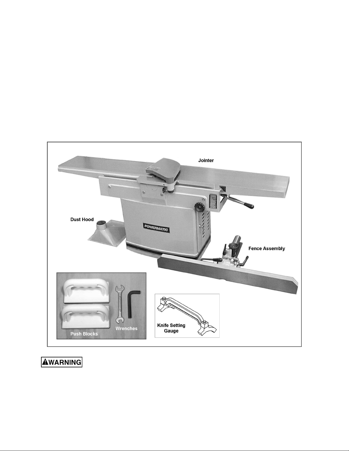
Contents of the Shipping Container
1 Jointer
1 Fence Assembly
1 Dust Hood
1 Knife Setting Gauge
1 Hex Wrench, 10mm
1 Combination Wrench, 10-12mm
2 Push Blocks
1 Owner's Manual
1 Warranty Card
Read and understand the entire contents of this manual before attempting set-up
or operation! Failure t o co mpl y may cause seri ou s injury.
8
Page 9
Assembly
Tools need for assembly:
10mm hex wrench (provi ded)
10-12mm combi nation wrench (provided)
forklift or hoist with straps
cross-point screwdriver
1. Remove top and sides of crat e from around
the machine.
2. Remove the dust hood and the fence
assembly from the skid. Reach into the
stand and remov e the screws securing the
stand to the skid.
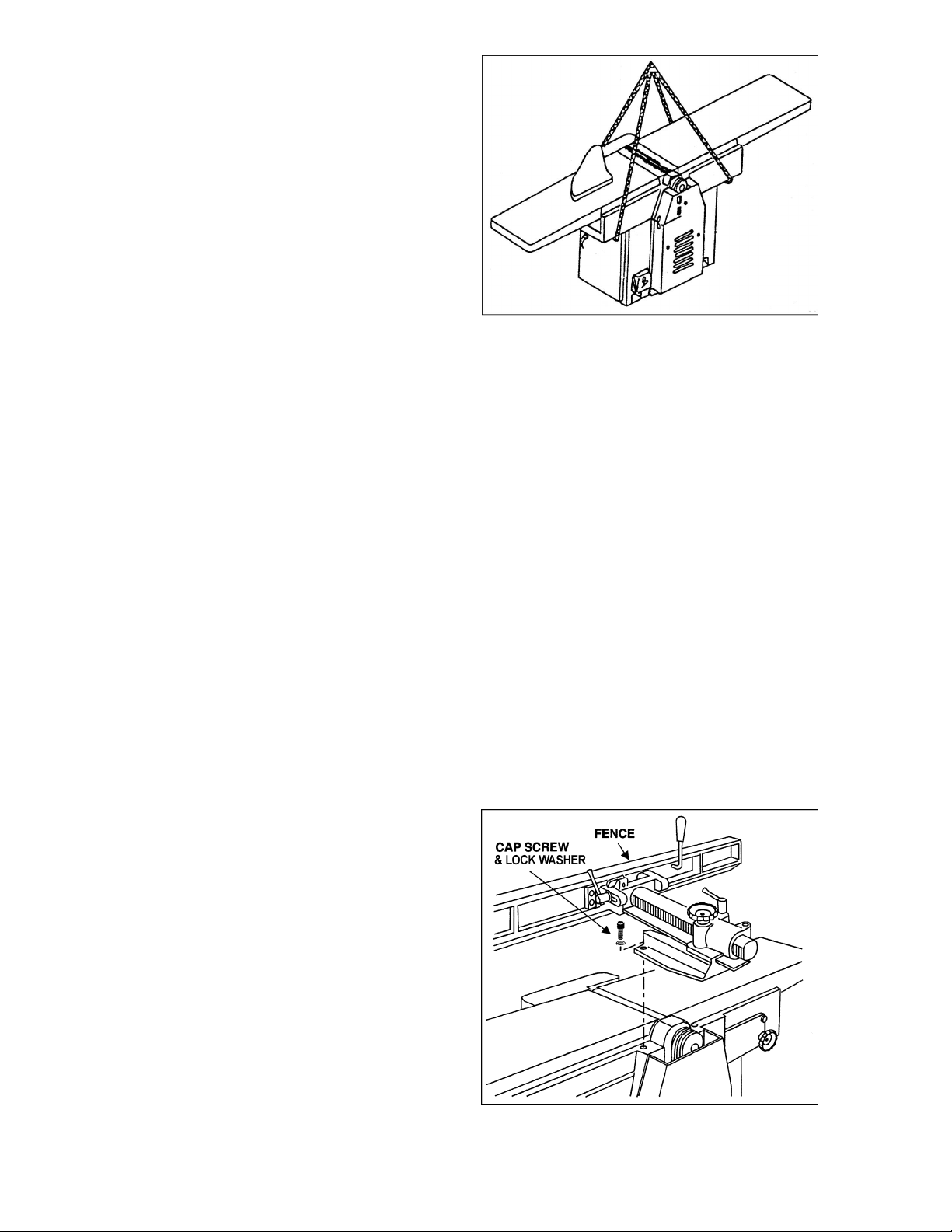
3. Raise the jointer off the skid with lifting
straps. The straps should be suitable to lift
762 pounds of weight, and shoul d be plac ed
under the base casti ng as shown in Figure
1. Do not lift the j ointer under t he infeed and
outfeed tabl es.
4. The jointer should be placed on a sturdy,
level floor in a dry area, with sufficient
lighting and v entilation. Leave enough room
around the machine for loading and
offloading stock and routine maintenance
work. The mac hine can be f urther stabi lized
by bolting it to the floor using lag screws
through the holes on the i nsi de of the stand.
5. This machine is equipped with noise-
reducing table lips. The work site should,
however, be one which minimizes
reverberant sound from walls, ceilings and
other equipment.
6. Exposed met al ar eas of the jointer, i ncl uding
the table and fence surfaces, have been
factory coated wit h a prot ectant. This should
be removed wit h a soft clot h dampened wit h
a solvent such as mineral spirits or
kerosene. Do not use ga soline, acetone or
lacquer thinner , and do not use an abrasive
pad. Do not let solvent contact the plastic
parts of the machine, as it may damage
them.
Figure 1
Fence Installation
1. Use an assistant to help place the fence
assembly on top the table, aligning the
holes in the fence assembly with the holes
in the table base, as shown in Fi gur e 2.
2. Use the two socket head cap screws and
two lock washers (Figure 2), and tighten
securely with a 10mm hex wrench.
Figure 2
9
Page 10

Switch Arm
The arm (Figure 3) on which the push button
switch is l oc ated is shipped in the down posi tion.
The arm should be pivot ed to upright positi on as
shown. Tighten the two screws with a 10mm
wrench.
Dust Hood
Before attaching the dust hood, make sure the
hole in the dust c hute is concealed by the dust
chute cover, as shown in Figure 4.
Mount the dust hood to the jointer stand using
the seven 1/ 4 x 1/2 hex cap screws and seven
1/4 lock washers (Figur e 5) .
It is recom mended that a dust coll ection system
of at least 800 CFM be connect ed to the jointer’s
dust hood, via a 6-inc h diam eter hose.
Grounding Instructions
Electrical connections must
be made by a qualified electrician in
compliance with all relevant codes. This
machine must be properly grounded to help
prevent electrical shock and possible fatal
injury.
Figure 3
Figure 4
This machine must be grounded. Grounding
provides a path of least resi stance to hel p divert
current away from the operator in case of
electrical malfunction.
Make sure the voltage of your power supply
matches the specif ications on the m otor plate of
the machine.
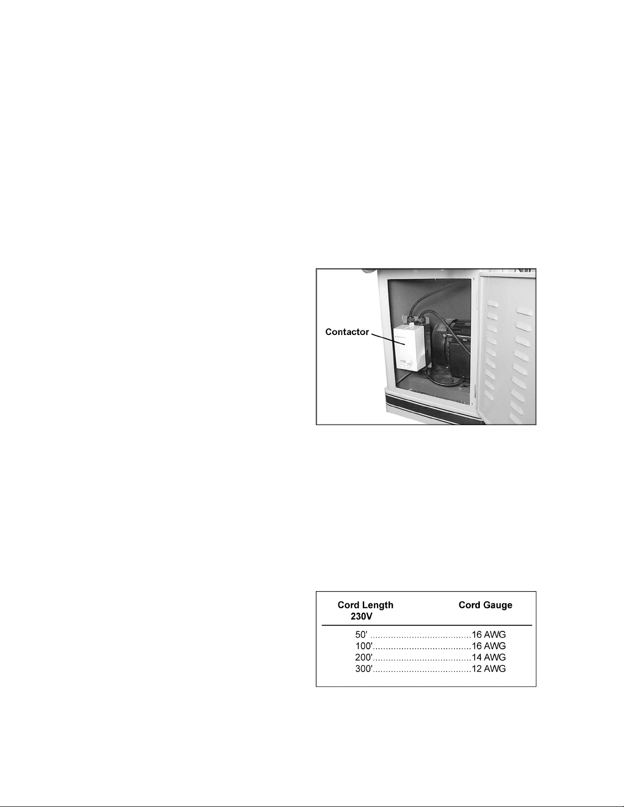
Open the junction box (Figure 6) and connect
the wires accordi ng t o the di agram on t he inside
of the juncti on box c over. A simi lar diagram can
be found at the back of this manual . The green
wire (ground) m ust be pr operl y gr ounded.
The Model 1285 may be fitted with an
appropriate plug, or be “hard-wired” to an
electric al panel. If hard-wired to a panel, mak e
sure a disconnect is available for the operator.
Figure 5
Figure 6
10
Page 11
If the jointer is to be hard-wired, make sure the
fuses have been r emoved or the breakers hav e
been tripped i n the circuit t o which the saw will
be connected. Place a warning placard on the
fuse holder or ci rcuit breaker to prev ent it being
turned on while the machine is being wired.
Always follow proper Lock-Out/Tag-Out
procedures when per forming any wiring on thi s
machine.
Voltage Conversion
The Model 1285 Jointer is wired for 1-phase,
230 volt only; or 3-phase, 230/460 v olt. The 3phase model i s pre-wired at the f actory for 230
volt. However, if you wish to convert your 3phase joint er from 230 volt t o 460 volt, proceed
as follows:
1. Disconnect machine from power source.
2. Remove cover fr om junction box, and open
the side door on the stand.
3. Change the wires in the junction box by
following the diagram on the inside of the
junction box cover, or the di agram found at
the back of this manual.
4. Replace the 230 volt contactor (see Figure
7) with the 460 volt contactor (stock no.
PJ1285-109). The 460 volt contactor is
available through your authorized
Powermatic distributor, or by calling 1-800274-6848.
5. If you are using a plug on the joi nter’s power
cord, install an appr opr iate 460 volt plug.
6. After wiring f or the new volt age, turn on the
machine and observe the rotation of the
cutterhead; it should be clockwise when
viewed from the front of machine. If it
rotates counterclockwise, disconnect jointer
from power source and switch any two of
the three wires at t he junc tion box.
7. Close junction box and r ec onnec t power.
Extens ion cords
The use of an extension cord is not
recommended, but if one is necessary make
sure the cord rati ng i s suit able f or t he amperage
listed on the machine’s motor plate. An
undersized cord will cause a drop in line voltage
resulting in loss of power and overheating.
Figure 7
Use the chart in Fi gure 8 as a general guide in
choosing the cor rect size cord. If in doubt, use
the next heavi er gauge. The smaller t he gauge
number, the heavier the cord.
Figure 8
11
Page 12
Adjustments
Disconnect jointer from
power supply before makin g ad ju st ments.
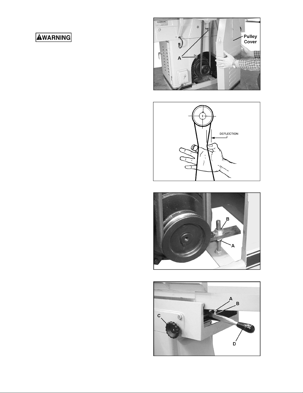
Drive Belt Tension
To check the tension of t he drive belts:
1. Rem ove the thr ee cap nuts and fl at washers
on the pulley cover with a 9/ 16 wrench, and
remove the guard to expose the belts and
pulleys. S ee Figure 9.
NOTE: The hex nuts and flat washers on the
threaded rods (A, Figure 9) should be left in
place; they keep t he pulley cover from bending
as it is being ti ghtened back into place with the
cap nuts.
2. There should be a small amount of
deflection in the belt when pressing it
midway between the pul leys with moderate
finger pressure (Figure 10).
3. If the belts need ti ght ening, loosen the l ower
hex nut (A, Figure 11) on the motor base
with a 19mm wrench.
Figure 9
4. Turn the top hex nut (B, Figure 11)
clockwise until proper tension is achiev ed.
5. Retighten lower hex nut (A, Figure 11).
NOTE: The belts should be inspected again
after the first f ew times the machine is used, as
the belts may stretch slightly during the
“breaking-in” process.
Setting Outfeed Table Height
For accurate work in most jointing operations,
the outfeed tabl e must be exactly level with the
knives/insert s at thei r highest poi nt of rev olution.
The outfeed table on t he Model 1285 has been
pre-set at the factory to the proper height in
relation to t he cutterhead. Howev er, the level of
the outf eed table should be checked i n case of
slight misadjustment during shipping. Outfeed
table height should also be inspected after resetting or replac ing knives/inserts.
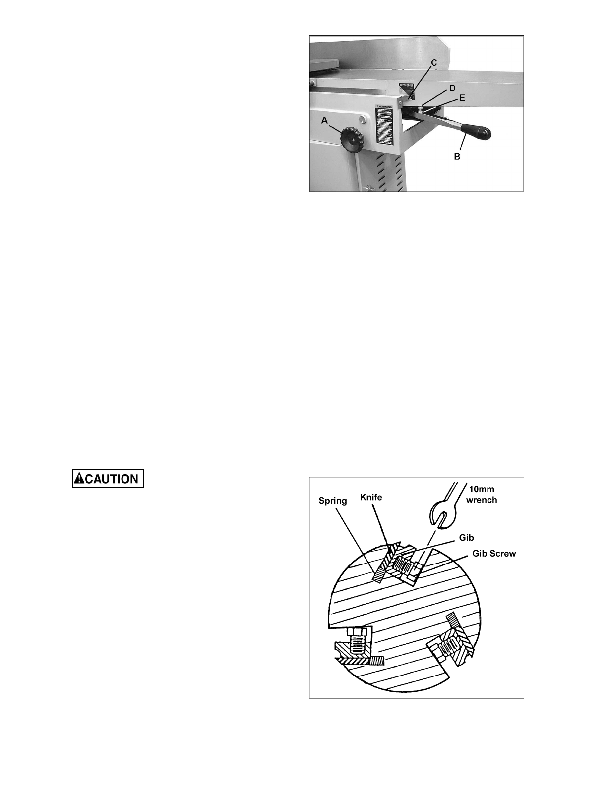
1. The outfeed table has a stop screw (A,
Figure 12) whic h, when contact ing the edge
of the table as shown, will ensure the
outfeed tabl e is at the proper height . Loosen
the handwheel (C, Figure 12) and raise the
outfeed tabl e adjustment arm (D, Figure 12)
until thi s stop screw (A, Fi gure 12) contact s
the edge of the table as shown.
Figure 10
Figure 11
Figure 12
12
Page 13
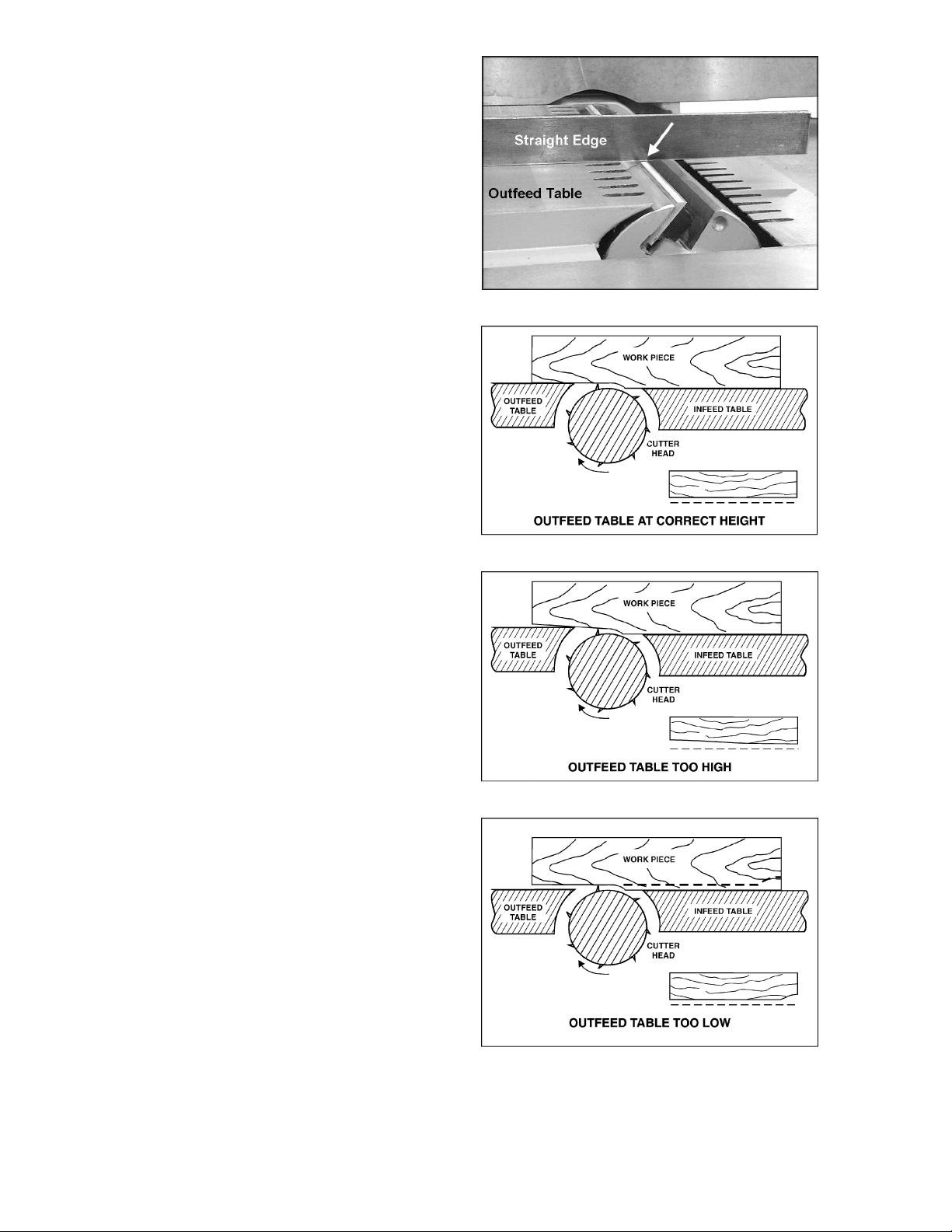
2. Place a straight edge on the outfeed table
and extending over the cutterhead, as
shown in Figure 13.
3. Rock the cut terhead slightly so that a knife
tip contacts the st raight edge. If the knif e tip
just contacts the straight edge without
moving the straight edge, then the outfeed
table is at the pr oper height. If the knife tip
pushes up the straight edge, the outfeed
table is too low. If the knife tip does not
contact the str aight edge, the outfeed tabl e
is too high.
4. To raise the height of the outfeed table,
loosen the hex nut (B, Fi gure 12) and rotate
the stop scre w (A, Figure 12) cl ockwise. To
lower the height of the outfeed table, rotat e
the stop screw (A, Figure 12) counter
clockwise.
5. When the outfeed table is level with the
knives, tighten the hex nut (B, Figure 12)
and firmly tighten the handwheel (C, Figure
12).
After the outfeed table has been set, it should
not be changed except f or speci al operations.
As a final check of the outf eed tabl e adjustment ,
turn on the jointer and run a scrap piece of wood
slowly over the knives for 6 to 8 inches; the
wood should rest firmly on both tables, as
shown in Fi gure 14, with no open space under
the finished cut.
If the outfeed table is too high, the finished
surf ace of the workpiece will be curved (Figure
15).
Figure 13
Figure 14
Figure 15
If the outf eed tabl e i s too l o w, the workpiece wil l
be gouged at the end of the cut (Fi gur e 16) .
Make further changes to the stop screw if
necessary to ensure the outfeed table is level
with the knives/inserts.
Figure 16
13
Page 14
Setting Infeed T able Height (Depth of
Cut)
1. To set t he cutting depth, loosen handwheel
(A, Figure 17) by turning counterclockwise.
2. Move table adjustment arm (B, Figure 17)
up or down to raise or lower infeed table.
The pointer (C, Figur e 17) shows the depth
of cut on the adjoining scale.
3. Tighten handwheel securely (A, Figure 17).
The stop screw (D, Figure 17) on the infeed
table should be set so that when it cont acts the
table, t he infeed table will be ex actly level with
the knives (wit h the scale pointer at zero). The
setting of this stop screw has bee n made at the
factory, but should be checked by the operat or
before using the jointer. It should also be
checked occasionally as the machine receives
use.
Use the same procedure as for the outfeed
table, placing the straightedge across outfeed
table, cutterhead and infeed table. Loosen the
hex nut (E, Figure 17) and adjust t he stop screw
(D, Figure 17) as necessary. When finished,
retighten hex nut (E, Figure 17).
If the infeed t abl e is lev el wit h the kniv es but the
scale pointer (C, Figure 17) appears to be off,
loosen the scale poi nter with a screwdriv er and
adjust it as needed unti l it reads zero. Ret ighten
the screw.
Replacing and Setting Knives (Straight Cutterhead)
Figure 17
Jointer knives are very
sharp. Use care and proceed slowly when
working with or around the cu t t erhead .
After a period of use, dull knives should be
reground or repl aced. Remove the pul ley cover
at the rear of the machine – this will allow you to
rotate the cutt erhead by using the belts.
To remove a knife:
1. Disconnect machine from power source.
2. Back the f ence away f rom the cutt erhead as
far as it will go. Lower infeed and outfeed
tables.
3. Tur n the six gib screws (Figure 18) into t he
gib with a 10mm wrench. A s the pressure of
the gib is released, the two springs in the
cutterhead slot wil l c ause the k nife to rise.
4. Carefully remove the knife from the
cutterhead.
Figure 18
14
Page 15

5. It is recommended when replacing knives
that you clean the knife slots in the
cutterhead. Rem ove the gib along with the
gib screws, and remove the two springs.
Clean the cutterhead slot of any debris or
dust that might prevent the knife from
seating properly. Also clean the gib, gib
screws, and spring s. Closely i nspect the gi b
screws – if the threads appear worn or
stripped, or if the heads are becoming
rounded, replac e the screws.
6. Re-insert the springs and the gib.
7. Place t he new or resharpened k nif e into t he
slot as shown in Fi gure 18, maki ng sure the
direction of the knife is correct.
8. Place the knife setting gauge (provided)
upon the cutterhead and centered over a
knife, as shown in Figure 19. Make sure the
feet of the knife setting gauge rest solidly
upon the cutterhead and that its handle is
parallel t o the c utt erhead. T he gauge i s now
holding the knife at proper depth.
9. While keeping the knife setting gauge in
place, tighten t he six gib screws just enough
to hold the knife in position. Start with the
center screws first, and work your way
toward the end screws.
10. Repeat steps 3 through 9 f or the other two
knives in the cutterhead. Make the gib
screws just ti ght enough to hold the kniv es
in position.
With all three jointer knives in the cutterhead,
the knives should now be tightened
incrementally to prevent any buckling or
distortion of the cutterhead. Proceed as foll ows:
11. Rotate the c ut terhead to each knife in turn,
tightening the gib screws a little more
(center screws first, then toward the end
screws). Do this at least twice; on the final
rotation, fi rmly tighten all gib screws.
After replaci ng and checking
knives, check again carefully. Make certain
the direction of knives is correct, and all
eighteen gib screws are tightened securely.
Loose gib screws can result in knives being
thrown from the cutterhead, causing severe
damage to the machi ne and po ssible serio us
or fatal injury to the operator or bystanders.
Figure 19
15
Page 16

Replacing Knife Inserts (Helical Cutterhead)
Jointer kni fe inserts are very
sharp. Use care and proceed slowly when
working with or around the cu t t erhead .
The helical cutterhead is a solid steel design
that holds 44 two-sided knife inserts, and two
rabbet knif e inserts on the outboard end of the
cutterhead. Replacing knife inserts is a simple
process, and they will seat themselves properly
without having to be set with a knife gauge.
After a period of use, dul l knife inserts should be
flipped over to present a new edge. If both
edges are worn, knife inserts should be
replaced.
1. Loosen the gib screw (A, Figure 20).
2. Rem ove the knife insert ( B, Figure 20) with
the gib (C, Figure 20) f r om its slot .
3. Make sure t he slot (D, Fi gure 20) is free of
dust and debris that would prevent the gib
and insert from seating properly. Wipe out
the slot and clean wit h solvent if needed.
4. Flip the knife insert 180 degree s and place it
onto the two pins of t he gib. Make sure the
knife edge faces the proper direction (see
Figure 21).
5. Re-install the gib into the slot.
6. Firmly tighten the gib screw (A, Figure 20).
NOTE: To ensure optimal cutting, all knife
inserts in the c utt erhead should be f lipped at the
same time. Of course, if an insert is nicked or
damaged, it can be flipped or replaced
individually as needed.
After install ing a knife insert, be sure to ti ghten
the gib screw befor e m oving on to t he next knife
insert.
Figure 20
Figure 21
Make certain the direction of
knife inserts is correct, and all gib screws
are tightened securely. Loose gib screws
can result in kn ife insert s being thrown fro m
the cutterhead, causing severe damage to
the machine and possible serious or fatal
injury to t he ope r a tor or by s t a n de r s .
16
Page 17

Fence Adjustments
The fence (A, Figure 22) tilts backward and
forward to 45 degrees. I t has a 90-degree stop
(B, Figure 22) and a 45-degree stop (C, Figure
22).
To tilt fence forw ard:
1. Loosen the lock handl e (D, Figure 22) and
tilt the fence forward using the handle (E,
Figure 22). NOTE: Lift up slightly on the
fence while tilting it, to prevent scratching
the table surface.
2. Retighten lock handle (D, Figure 22).
To tilt fence backw ard:
1. Loosen the lock handl e (D, Figure 22) and
pivot the stop bl oc k (F , Fi gure 22) out of the
way.
2. Tilt the fence using the handle (E, Figure
22). NOTE: Lift up slightly on the fence
while tilti ng it to prevent scratching the t able
surface.
3. Retighten lock handle (D, Figure 22).
To move fence forward or backward:
1. Loosen lock handle (G, Figure 22) and
rotate handwheel (H, Figure 22);
counterclockwise for forward fence
movement, clockwise for backward fence
movement.
2. When desi red position is reached, securel y
tighten lock handle (G, Figure 22).
To check and adjust the 90-d egree stop :
1. Loosen lock handle (D, Figure 23) and tilt
fence until the stop screw (B, Figure 23)
contacts the stop block (F, Figure 23).
Figure 22
2. Place a square or machini st’s protractor (not
provided) on t he table and flush against t he
fence surface. S ee Figure 23.
3. If adjustment is necessary, loosen the hex
nut on the stop screw (B, Figure 23) and
turn the stop screw as needed until the
fence is flush with your square.
4. Retighten the hex nut .
Figure 23
17
Page 18

To check and adjust the 45-d egree stop :
1. Loosen lock handle (D, Figure 22) and tilt
fence until it contacts the 45-degr ee stop (C,
Figure 22).
2. Place a machinist’s protractor or similar
device set at 45 degrees on the table and
against the fence.
3. If adjustment is necessary, loosen the hex
nut on the stop screw (C, Figure 22) and
turn the stop screw until the fence is flush
with the protr actor .
4. Retighten the hex nut .
Cutte r Guard Tension
The tension of the guard (Figure 24) must
always be suffic ient during jointer operations to
cause the guard to conceal the unused part of
the cutterhead, and to s wing back t o cont act t he
fence after the workpiece has cleared the
cutterhead. To adjust the guard tension:
1. Loosen the knob shown in Figure 24 and
push the knob to the ri ght to incr ease guard
tension; or to the left to decrease guard
tension.
2. Tighten the knob in that position.
Operating Controls
The push button on/off switch is conveniently
positioned above the table (Figure 25). Do not
remove the clear plastic cover, as this keeps
wood dust out of the switch.
Operation
NOTE: If y ou are inexperienced at jointing, use
scrap pieces of lumber to c hec k set tings and get
the feel of operati ons before attem pting regular
work.
Always use the guard
whenever possible and keep hands away
from cutterhead. Failure to comply may
cause serious injury.
Ideally, the fence should be moved forward
(toward the f r ont of the m achine) to ex pose only
the amount of cutterhead needed for the
workpiece.
Figure 24
Figure 25
TIP: If workpieces of the same size are
constantly bei ng run on the joi nter, the operator
may wish to occasionally adjust the fence
forward or backward to prevent wear on only
one area of the knives.
18
Page 19

Hand Placement
At the start of the cut, the left hand holds the
workpiece firmly against the infeed table and
fence, while the right hand pushes the
workpiece toward the knives. After the cut is
under way, the j ointed surf ace of the workpi ece
rests firmly on the outfeed table. The left hand
should press down on this part, at the same time
maintaining flat contact of the workpiec e with the
fence. The right hand pushes the workpiece
forward and before the right hand reaches the
cutterhead, the right hand shoul d be moved to
the workpiece on the outfeed table. The
workpiece is then pushed on through to
complete the cut. Follow the 3-inch rule (see
page 5). Never pass hands directly over the
cutterhead.
Edge Jointing
This is the most common operation for the
jointer. S et the fence to the 90-degree stop and
thus square with the t able. Depth of cut should
be the minimum required to obtain a straight
edge. Do not m ake cuts deeper than 1/8” in a
single pass. Hol d the be st f ace of t he workpiec e
firmly against the fence throughout the feed.
See Figure 26.
Surfacing
Figure 26
Jointing the fac e of stock, or surfacing is shown
in Figure 27. Adjust the infeed tabl e for depth of
cut. Cuts of approximately 1/16” at a time are
recommended, as this allows better control over
the material being surfaced. More passes can
then be made to reach the desir ed depth.
Always use a hold-down or
push block when surfacing short stock or
stock less than 3 inches thick. Figure 26
shows push blocks being used fo r surfacing.
Rabbeting
A rabbet is a groove cut along the edge of a
workpiece. See Figure 28. The width and
thickness of the workpiece used will be
dependent upon the de sired width and l ength of
the rabbet. However , never rabbet a workpiece
less than 12 inches long.
A rabbet cut requires
removal of the cutterhead guard. Use
extreme caution and keep hands clear of
cutterhead. Always replace guard
immediately after rabbeting operation is
completed.
Figure 27
Figure 28
19
Page 20

Use push blocks to rabbet cut whenever
possible. The rabbeting capacity is 3/4”.
1. Disconnect machine from power source.
2. Set fence for desir ed width of rabbet.
3. Check width of the r abbet by m easuring the
distance from the end of a knife in the
cutterhead to the fence.
4. Reconnect power. Lower the infeed table
1/32” at a time and make successive cuts
until the desired depth of rabbet has been
obtained. See F igure 28. NOTE : It is easier
and safer to take a seri es of shall ow cuts.
Jointing Warped Surfaces
If the wood to be jointed is di shed or warped,
take light cuts until the surface is flat. Avoid
forcing such material down against the tabl e;
excessive pressure will spring it while passing
the knives, and it will spring back and remain
curved after the cut is completed.
Jointing Short or Thin Work
When jointing short or thin pi eces, use a push
block to elimi nate all danger to t he hands. Two
push blocks are shipped with your jointer, and
additional ones (stock no. 6285917) can be
purchased fr om your distri butor or by calling 1800-274-6848. You can also make your own
easily from scrap material. Three types of
commonly used push block s are represented in
Figure 29.
Direction of Grain
Avoid feeding work into the jointer against the
grain. This will result in chipped and splintered
edges. See Figure 30. Feed with the grain to
obtain a smooth surfac e, as shown in Figure 31.
Beveling
To cut a bevel, lock the fence at the required
angle and run t he workpiece across the kniv es
while keeping it firmly against the fence and
tables. Several passes may be necessary to
achieve the desi r ed r esul t.
Figure 29
Figure 30
While the fence can be tilt ed in or out for bevel
cutting, it is recommended for safety reasons
that the f ence be ti lted i n toward the operat or, i f
possible, making a cradled cut.
Figure 30
20
Page 21

Maintenance
Disconnect machine from
power source before performing any
maintenance. Failure to comply may cause
serious injury.
Check all screws and f astener s occasionally and
keep them tightened secur ely.
Inspect cords; a cord t hat is frayed or dam aged
in any way should be replac ed immediately.
The table and fence surfaces must be kept
clean and free of rust for best results. Some
users prefer a paste wax c oating. Another opti on
is talcum powder applied with a blackboard
eraser rubbed in vigorously once a week; this
will fill casting pores and form a moisture barrier.
This method provides a table top that is slick
and allows rust ri ngs to be easil y wiped from the
surface. Important also is the fact that talcum
powder will not stain wood or mar finishes as
wax pickup does.
Lubrication
The cutterhead runs in two single-row sealed
and shielded ball bearings, which are prelubricated for life - no maintenance is necessary.
Occasionally apply a good grade of light grease
to areas of the joint er where fricti on may occur,
such as when the tables are raised or lowered.
Cutterhead Repairs
The entire cutterhead assembly may be
removed for bearing replacement or other
cutterhead maintenance procedures. The
procedure is identical for both helical and
straight cutt er heads.
To remove the cutterhead:
1. Disconnect machine from power source.
2. Remove rabbeti ng ledge and fence.
3. Lower infeed and outfeed tables until they
are clear of the cutterhead.
4. Remove belts.
5. Remove the two hex cap screws and lock
washers that hold t he cutterhead to the bed
– these are accessed fr om the underside of
the bearing block s as shown in Figure 32.
Before removing cutterhead,
wrap it with several cloths to prevent
perso nal inju r y .
Figure 32
21
Page 22

6. Slide the cutt er head out the rabbeting side.
7. Loosen hex cap screw (A, Figure 33) and
remove pulley (B, Figure 33) and key (C,
Figure 33).
8. Loosen screws (D, Figure 33) on both sides
and remove bearing cap plates (E, Figure
33).
NOTE: Figure 33 shows the pulley end of
the cutterhead. The procedure is sim ilar for
breaking down the opposite end of the
cutterhead - refer to assembl y drawing on
page 39 for the specifi c parts.
IMPORTANT: If the bearings (G, Figure 33)
need replacement, it is strongly recommended
this be done by qualif ied service personnel . The
bearings are press f itted and must be removed
with an arbor press.
9. To re-install the cutterhead, reverse the
above procedure. NOTE: Before reinstalling, make sure the machine’s curved
seats of the base casting are free of dirt,
dust or grease, whi c h will help ensure a ti ght
fit.
Knife Inserts (Helical Cutterhead)
When knife insert s become dull enough so that
it is noticeable when cutting, they should be
turned over or replaced entirely. A sharp knife
works easier and results in longer blade life. The
penalty pai d for a dull k nife is less blade l if e and
greater wear and tear on all parts of the
machine.
An advantage of the helical style cutterhead is
that if knif e inserts develop nicks, these insert s
can be individually flipped or replaced without
the need to disturb the other inserts. See
“Replacing Knife Inserts (Helical Cutterhead)”
for this procedure.
If the jointer is used oft en, keeping a spare set
of knife inserts on hand is recom mended. Knife
inserts (stock no. 6400013) may be ordered
from your authorized Powermatic distributor or
by calling 1-800-274- 6848.
Gum and pitch which c ollect on the knif e inserts
cause excessiv e friction as the work cont inues,
resulting in overheating of the inserts, less
efficient cutting, and consequent loss of blade
life. Use "Gum and Pitch Remover" or oven
cleaner, to carefully wipe off the knife inserts.
Figure 33
Jointer kni fe inserts are very
sharp. Use care and proceed slowly when
working with or around the cu t t erhead .
22
Page 23

Whetting Knives (Straight Cutterhead)
When knives become dull enough so that it is
noticeable when cutting, they should be
resharpened or repl aced. A sharp knif e will work
easier and last longer. The penalty paid for a
dull knif e is less blade life and greater wear and
tear on all parts of t he machine.
Jointer knives are very
sharp. Use care and proceed slowly when
working with or around the cu t t erhead .
1. Disconnect machine from power source.
2. Rem ove the pulley cover so you can r otate
the cutterhead by means of t he belts.
3. Use a fine carborundum stone. Cover it
partly wit h paper, as shown in Fi gure 34, to
avoid marking the table.
4. Lay t he stone on the i nf eed table. Adjust the
infeed table and t urn the cutter head until t he
stone lies f lat on the bev el of the knife and
flat on the infeed table.
Figure 34
5. Hold the c utterhead from turning, and whet
the beveled edge of the knife, stroking
lengthwise by sliding the stone back and
forth across the tabl e. Do the same amount
of whetting on each of the thr ee k niv es.
6. When finished, reset the knives parallel to
the outfeed table. See “Setting Knives
(Straight Cutterhead)”.
If knives cannot be properly retouched as
described above, they must be ground and resurfaced to a new bevel edge. Check in the
phone directory under “Sharpening Service” or
“Tool Grinding or Sharpening.” It may be less
expensive to purchase a new set of knives. If
the joint er is used often, keeping a spare set of
knives on hand is recomm ended.
Knives (stock no. 6292535) may be ordered
from your authorized Powermatic distributor or
by calling 1-800-274- 6848.
Gum and Pitch which collect on the knives
cause excessiv e friction as the work cont inues,
resulting in overheating of the knives, less
efficient cutting, and consequent loss of blade
life. Use "Gum and Pitch Remover" or oven
cleaner, to carefully wipe off the knives.
23
Page 24

Troubleshooting – Operating Problems
Trouble Probable Cause Remedy
Finished stock i s
concave on back
end.
Finished stock i s
concave on front end.
Finished stock i s
concave in the
middle.
Ends of finished
stock are cut more
than the middle.
Knife is higher than outfeed table.
Outfeed table is higher than knife.
Both tables have t oo much end f all . Raise both table ends using the
Table ends are rai sed hi gher than t he
middle.
Raise outfeed table until it aligns with
tip of knife. (see page 13)
Lower outfeed table until it aligns with
tip of knife. (see page 13)
adjustment screws below the t ables
(see Figure 35).
Figure 35
Lower both table ends using the
adjustment screws under the tables
(see Figure 35).
Chip out.
Fuzzy grain.
Cutterhead slows
while operating.
“Chatter” marks on
workpiece.
Cutting against the grain. Cut with the grain whenev er possible.
Dull knives/i nsert s. Sharpen or replac e k niv es/inserts.
Feeding workpiec e too fast. Use slower rate of feed.
Cutting too deepl y. Make shallower cuts.
Knots, imperfections in wood.
Wood has high moistur e c ontent. Allow wood to dry or use diff er ent stock.
Dull knives/i nsert s. Sharpen or replac e k niv es/inserts.
Feeding workpiec e too quickly, or
applying too much pressure to
workpiece.
Knife/inserts incorrectly set.
Feeding workpiec e too fast.
Inspect wood closely for imperfections;
use different stock if necessary.
Feed more slowly, or appl y l ess
pressure to workpiece.
Set knives properl y usi ng pr ov ided k nife
setting gauge (straight cutterhead onl y
– see page 15). Check that insert sl ots
are clean and free of dust or debri s
(helical cutterhead only).
Feed workpiece slowly and
consistently.
24
Page 25

Trouble Probable Cause Remedy
Uneven knife marks
on workpiece.
Knives/inserts are knicked, or out of
alignment.
Replace knicked k nives/inserts; align
knives properl y with knife-setting gauge
(straight c utt er head only).
Troubleshooting – Mec hanical and Elect rical Problems
Trouble Probable Cause Remedy
Machine will not
start/restart or
repeatedly t rips
circuit breaker or
blo ws fu ses.
No incoming power.
Overload aut omatic reset has not
reset.
Jointer frequently trips.
Building circuit breaker trips or fuse
blows.
Motor starter failure.
Verify unit is connected to power, and
on-switch i s pushed in com pletely.
When jointer overloads on the circuit
breaker built into the motor starter, it
takes time for the machine to cool
down before restar t. Allow unit to
adequately cool bef ore attempting
restart. If pr oblem persists, check
amp setting on the mot or start er
inside the electrical enclosure.
One cause of overl oading trips which
are not electric al in nature is too
heavy a cut. The solution is to take a
lighter cut. If too deep a c ut is not t he
problem, then chec k the amp setting
on the overload rel ay . Match the full
load amps on the motor as noted on
the mo tor plate. If amp se tting is
correct then ther e is probably a loose
electric al lead. Check amp setting on
motor starter.
Verify that jointer is on a circuit of
correct size. If circuit size is correct,
there is probabl y a loose el ectr ic al
lead. Check amp setting on motor
starter.
If you have access to a voltmeter, you
can separate a starter f ailure from a
motor fai lu re by fi r st, verify ing
incoming voltage at 220+/-20 and
second, checking the voltage
between starter and motor at 220+/-
20. If incoming voltage is incorrect,
you have a power supply problem. If
voltage between start er and m otor is
incorrect, y ou hav e a starter pr oblem.
If voltage bet ween start er and m otor
is correct, you hav e a motor pr oblem .
Motor overheat ed.
Clean motor of dust or debri s to allow
proper air circulation. Allow motor to
cool down before r estar ting.
25
Page 26

Trouble Probable Cause Remedy
Motor failure.
Miswiring of the unit.
On/off switch failure.
If electri c mot or i s suspect, you have
two options: Have a qualified
electrician test the motor for function
or remove the motor and take it t o a
qualified elec tric motor repair shop
and have it tested.
Double check to confirm all electrical
connections are cor r ec t and properly
tight. The elect ri c al c onnec tions other
than the motor are pre- assembled
and tested at the factory. Therefore,
the motor connections should be
double checked as the highest
probability for error. If problems
persist, double c hec k the factory
wiring.
If the on/off switch is suspect, you
have two options: Hav e a qualified
electrician test the switch for function,
or purchase a new on/off switc h and
establish if that was the pr oblem on
changeout.
26
Page 27

Optional Accessori es
6292535 12” Jointer Knives (set of 3)
6400013 Carbide Insert Knives for Heli c al Head (set of 10)
PJ1696-011 Rabbet Inserts for Helic al Head (set of 2)
PJ1285-109 Contactor, 3P h, 460V
6285917 Push Block
Replacement Parts
Replacement part s are li sted on the f ollowing page s. To order par ts or reac h our servi ce depar tment, call
1-800-274-6848 between 7:00 a.m. and 6:00 p.m. (CST), Monday through Friday. Having the Model
Number and Serial Number of your machine available when you call will allow us to serve you quic kly and
accurately.
27
Page 28

Parts List: Stand Assembly
Index No. Part No. Description Size Qty
1...............PJ1285-101............. Stand........................................................... .........................................1
2...............TS-0680041............ Flat Washer.................................................3/8”...................................4
3...............TS-0720091............ Lock Wash e r ................................................3/8”...................................4
4...............TS-0060051............ Hex Cap Screw............................................3/8”-16x1”.........................4
5...............6292491.................. Cover, Dust Chute....................................... .........................................1
6...............TS-081C022............ Machine Screw, Pan Head, Phillips..............#10-24x3/8”....................... 5
7...............6292493.................. Motor Assembly, Motor With Pulley..............3HP, 3Ph..........................1
................. 6295366.................. Motor Assembly, Motor With Pulley..............3HP, 1Ph..........................1
8...............6292494.................. Plate, Switch................................................ .........................................1
9...............6295112.................. Contactor.....................................................1Ph ...................................1
................. 6292495.................. Contactor.....................................................3Ph, 230V.........................1
................. PJ1285-109............. Contactor.....................................................3Ph, 460V.........................1
10.............PJ1285-110............. Clamp..........................................................3Ph...................................3
................. PJ1285-110A .......... Clamp..........................................................1Ph...................................3
11.............6292497.................. Box, Junction............................................... .........................................1
12.............6292498.................. Strip, Ter m ina l............................................. .........................................1
13.............TS-081C062............ Machine Screw, Pan Head, Phillips .............#10-24x1” .........................2
14.............TS-0720051............ Lock Wash e r................................................#10...................................2
15.............PJ1696-211............. Switch.......................................................... .........................................1
16.............PJ1285-116............. Hood, Dust .................................................. .........................................1
17.............TS-0720071............ Lock Wash e r................................................1/4”...................................9
18.............TS-0050011............ Hex Cap Screw............................................1/4”-20x1/2”......................7
19.............6292507.................. Cover, Pulley............................................... .........................................1
20.............6292508.................. Bolt.............................................................. .........................................3
22.............TS-0561031............ Hex Nut.......................................................3/8”-16..............................6
23.............TS-059303.............. Cap Nut.......................................................3/8”-16..............................3
24.............6292510.................. Door, Access............................................... .........................................1
25.............6292511.................. Hand Assembly ........................................... .........................................1
26.............PJ1285-126............. Washer........................................................3/8”x3/4 OD......................1
27.............PJ1696-210............. Switch Arm .................................................. .........................................1
28.............TS-1533052............ Machine Screw, Pan Head, Phillips..............M5x16...............................2
29.............PJ1285-129............. Switch Cord................................................. .........................................1
30.............PJ1285-130............. Motor Cord ..................................................1Ph...................................1
................. PJ1285-130A .......... Motor Cord..................................................3Ph...................................1
31.............PJ1285-131............. Power Cord .................................................1Ph...................................1
................. PJ1285-131A .......... Power Cord .................................................3Ph...................................1
32.............3312341.................. Powermatic Logo......................................... .........................................1
28
Page 29

Stand Assembly
29
Page 30

Parts List: Table Assembly
Index No. Part No. Description Size Qty
1...............6292525.................. Base............................................................ .........................................1
2...............6292526.................. Bar, Tabl e Raising Link................................ .........................................2
3...............6292527.................. Bracket........................................................ .........................................2
4...............TS-0680041............ Lock Wash e r ................................................3/8”...................................8
5...............TS-0209051............ Socket Head Cap Screw..............................3/8”-16x1”.........................4
6...............6292530.................. Bushing....................................................... .........................................8
7...............6292531.................. Support........................................................ .........................................8
8...............6292532.................. Bushing....................................................... .........................................8
9...............6292533.................. Axis, Pivot.................................................... .........................................4
10.............6292534.................. Screw.......................................................... .........................................2
11.............TS-0680061............ Flat Washer.................................................1/2”...................................2
12.............6292536.................. Handwheel .................................................. .........................................2
13.............6292537.................. Handle......................................................... .........................................2
14.............TS-0209061............ Socket Head Cap Screw ..............................3/8”-16x1-1/4”...................4
15.............TS-1490041............ Hex Cap Screw............................................M8x25...............................2
16.............TS-1540061............ Hex Nut.......................................................M8 ....................................4
17.............6292540.................. Knob............................................................ .........................................2
18.............6292541.................. Axis, Pivot.................................................... .........................................8
19.............TS-0208071............ Socket Head Cap Screw ..............................5/16”-18x1-1/4”.................8
20.............6292543.................. Bar,Table Raising Link................................. .........................................2
21.............6292544.................. Axis, Pivot.................................................... .........................................4
22.............6292545.................. Screw.......................................................... .........................................8
23.............TS-0561031............ Hex Nut.......................................................3/8”-16............................24
24.............6292547.................. Tube............................................................ .........................................2
25.............6292548.................. Spring.......................................................... .........................................4
26.............PJ1696-509............. Spring Holding Bolt...................................... .........................................4
27.............6292550.................. Straight Cutterhead Assembly...................... .........................................1
................. PJ1285-600............. Helical Cutterhead Assembly ....................... .........................................1
28.............TS-1491041............ Hex Cap Screw............................................M10x30.............................2
29.............6292551.................. Infeed Table ................................................ .........................................1
30.............6292552.................. Lip, Table ..................................................... .........................................1
31.............TS-1505061............ Socket Head Cap Screw ..............................M10x40.............................8
32.............6292554.................. Deflector, Dust ............................................. .........................................1
33.............TS-081C062............ Machine Screw, Pan Head, Phillips .............#10-24x1” .........................5
34.............TS-0680011............ Flat Washer.................................................3/16”.................................5
35.............TS-0560071............ Hex Nut.......................................................#10-24 ..............................5
36.............6292558.................. Outfeed Table.............................................. .........................................1
37.............6292559.................. Lip,Table...................................................... .........................................1
38.............6292560.................. Guard Assembly.......................................... .........................................1
39.............TS-2361101............ Lock Wash e r................................................M10..................................2
40.............PJ1285-240............. Pointer......................................................... .........................................1
41.............PJ1285-241............. Scale........................................................... .........................................1
42.............TS-0680011............ Flat Washer.................................................3/16”.................................1
43.............TS-081C022............ Machine Screw, Pan Head, Phillips..............#10-24x3/8”.......................1
44.............TS-0680041............ Flat Washer.................................................3/8”.................................24
45.............TS-0271051............ Socket Set Screw ........................................3/8”-16x1/2”......................4
46.............TS-0271031............ Socket Set Screw ........................................3/8”-16x3/8”......................4
47.............TS-0561011............ Hex Nut.......................................................1/4”-20..............................4
48.............6285917.................. Push Block .................................................. .........................................2
49.............PJ1285-249............. Set Screw....................................................M8x35...............................2
30
Page 31

Table Assembly
31
Page 32

Parts List: Motor Pulley Assembly
Index No. Part No. Description Size Qty
1...............6292512.................. Motor...........................................................3HP 3Ph...........................1
................. 6292512-MF............ Motor Fan (not shown) ................................ .........................................1
................. 6292512-MFC......... Motor Fan Cover (not shown) ...................... .........................................1
................. 6292563.................. Motor...........................................................3HP 1Ph...........................1
................. 6292563-MF............ Motor Fan (not shown) ................................ .........................................1
................. 6292563-MFC......... Motor Fan Cover (not shown) ...................... .........................................1
................. 6292563-CS............ Centrifugal Switch (not shown) .................... .........................................1
................. 6292563-SC............ Starting Capac itor (not shown) ....................400MFD, 250VAC.............1
................. 6292563-RC............ Running Capacitor (not shown) ...................50uf, 350VAC ...................1
2...............6292513.................. Pulley..........................................................3Ph...................................1
................. 6294246.................. Pulley..........................................................1Ph...................................1
3...............TS-1525011............ Socket Screw Screw....................................M10x10.............................1
4...............6292515.................. Bracket, Motor............................................. .........................................1
5...............TS-0680041............ Flat Washer.................................................3/8”...................................3
6...............TS-0720091............ Lock Wash e r ................................................3/8”...................................6
7...............TS-0060081............ Hex Cap Screw............................................3/8”-16x1-3/4”...................3
8...............TS-0561031............ Hex Nut.......................................................3/8”-16..............................3
9...............6292520.................. Plate............................................................ .........................................1
10.............6292521.................. Rod ............................................................. .........................................1
11.............TS-2360121............ Flat Washer.................................................M12..................................2
12.............TS-1540081............ Hex Nut.......................................................M12 ..................................8
13.............TS-1525021............ Socket Set Screw ........................................M10x12.............................1
14.............6295367.................. Belt, 1PH.....................................................A-53..................................2
................. 6295357.................. Belt, 3PH.....................................................A-55..................................2
15.............PJ1285-315............. Key..............................................................8mmx 7mm x 55mm..........1
32
Page 33

Motor Pulley Assembly
33
Page 34

Parts List: Cutterhead Guard Assembly
Index No. Part No. Description Size Qty
1...............6292581.................. Ledge, Rabbet............................................. .........................................1
2...............6292582.................. Guard.......................................................... .........................................1
3...............6292583.................. Shaft............................................................ .........................................1
4...............6292584.................. Spring.......................................................... .........................................1
5...............6292585.................. Collar, Shaft................................................. .........................................1
6...............TS-0271071............ Socket Set Screw........................................3/8”-16x3/4”......................1
7...............TS-0267071............ Socket Set Screw........................................1/4”-20x3/4”......................2
8...............TS-0561011............ Hex Nut.......................................................1/4”-20..............................2
9...............6292589.................. Knob............................................................ .........................................1
10.............TS-0720091............ Lock Wash e r................................................3/8”...................................2
11.............TS-0209031............ Socket Head Cap Screw ..............................3/8”-16x3/4”......................2
12.............TS-0680041............ Flat Washer.................................................3/8”...................................2
13.............60B-272.................. Warning Label............................................. .........................................1
34
Page 35

Cutterhead Guard Assembly
35
Page 36

Parts List: Straight Cutterhead Assembly
Index No. Part No. Description Size Qty
................. 6292550.................. Cutterhead Assembly (It em s 1 thru 19)………..........................................
1...............6292561.................. Cutterhead .................................................. .........................................1
2...............PJ1696-002............. Left Bearing Housing ................................... .........................................1
3...............BB-6204ZZ..............Bearing ....................................................... 6204ZZ .............................2
4...............PJ1696-005............. Right Bearing Housing................................. .........................................1
5...............BB-6206ZZ..............Bearing........................................................6206ZZ.............................2
6...............6292566.................. Bearing Wash er........................................... .........................................1
7...............TS-1490031............ Hex Cap Screw............................................M8x20...............................1
8...............TS-1503051............ Socket Head Cap Screw..............................M6x20...............................6
9...............6292572.................. Pulley.......................................................... .........................................1
10.............6292573.................. Key..............................................................8mmx8mmx60mm ............1
11.............6292574.................. Pulley Washe r............................................. .........................................1
12.............TS-2361101............ Lock Wash e r................................................M10..................................1
13.............TS-1491021............ Hex Cap Screw............................................M10x20.............................1
14.............6292577.................. Spring.......................................................... .........................................6
15.............6292535.................. Knife (set of 3)............................................. .........................................1
16.............6292579.................. Gib, Knife(set of 3)....................................... .........................................1
17.............6292580.................. Gib Screw.................................................... .......................................18
18.............PJ1696-004............. Left Bearing Cap Plate................................. .........................................1
19.............PJ1696-006............. Right Bearing Cap Plate............................... .........................................1
................. PJ1285-KSGA......... Knife Setting Gauge Assembly (Items 20 thru 23) ....................................
20.............PJ1285-520............. Handle......................................................... .........................................1
21.............PJ1285-521............. Setting Gauge.............................................. .........................................2
22.............TS-1482051............ Hex Cap Screw............................................M6x25...............................2
23.............TS-2361061............ Lock Wash e r................................................M6....................................2
36
Page 37

Straight Cutterhead Assembly
37
Page 38

Parts List: Helical Cutterhead Assembly
Index No. Part No. Description Size Qty
................. PJ1285-600............. Cutterhead Assembly (It em s 1 thru 22)… ……..........................................
1...............PJ1285-601............. Cutterhead................................................... .........................................1
2...............PJ1696-002............. Left Bearing Housing ................................... .........................................1
3...............BB-6204ZZ..............Ball Bearing.................................................6204ZZ.............................2
4...............6292566.................. Bearing Wash er........................................... .........................................1
6...............TS-1490031............ Hex Cap Screw............................................M8x20...............................1
7...............PJ1696-004............. Left Bearing Cap Plate................................. .........................................1
8...............TS-1503051............ Socket Head Cap Screw..............................M6x1.0Px20L....................6
9...............PJ1696-005............. Right Bearing Housing................................. .........................................1
10.............BB-6206ZZ..............Bearing........................................................6206ZZ .............................2
11.............PJ1696-006............. Right Bearing Cap Plate............................... .........................................1
12.............6292573.................. Key..............................................................8mm x 8mm x 60mm ........1
13.............6292572.................. Cutterhead Sheave ...................................... .........................................1
14.............6292574.................. Pulley Washe r............................................. .........................................1
15.............TS-2361101............ Lock Wash e r................................................M10..................................1
16.............TS-1491021............ Hex Cap Screw............................................M10x20.............................1
17.............PJ1696-010............. Gib .............................................................. .......................................46
18.............PJ1696-011............. Carbide Insert Knife-Rabbet (Sold in pkg of 2)........................................2
19.............6400013.................. Carbide Insert Knife (Sold in pkg of 10)........ .......................................44
20.............PJ1696-012............. Gib Nut ........................................................ .......................................46
21.............PJ1696-013............. Gib Screw.................................................... .......................................46
ʳ2xʳ
22.............PJ1696-015............. Gib Pin........................................................
8.............................92
38
Page 39

Helical Cutterhead Assembly
39
Page 40

Parts List: Fence Assembly
Index No. Part No. Description Size Qty
1...............6292592.................. Support, Fence............................................ .........................................1
2...............6292593.................. Bracket........................................................ .........................................1
3...............6292594.................. Column, Ge a r.............................................. .........................................1
4...............6292595.................. Guard.......................................................... .........................................1
5...............TS-1503031............ Socket Head Cap Screw..............................M6x12...............................2
6...............TS-1550071............ Flat Washer.................................................M10..................................4
7...............TS-2361101............ Lock Wash e r ................................................M10..................................4
8...............TS-1491041............ Hex Head Bolt .............................................M10x30.............................2
9...............TS-1505041............ Socket Head Cap Screw..............................M10x30 ............................ 2
10.............6292601.................. Shaft,Gear .................................................. ......................................... 1
11.............6292602.................. Handwheel .................................................. .........................................1
12.............6292603.................. Lock Handle ................................................ .........................................1
13.............6295358.................. Collar........................................................... .........................................1
14.............6292604.................. Bolt ............................................................. ......................................... 1
15.............TS-0720111............ Lock Wash e r................................................1/2”...................................2
16.............6295886.................. Socket Head Cap Screw..............................1/2”-12NCx1-1/4”..............2
17.............6292605.................. Bracket, Fence............................................ .........................................1
18.............6292606.................. Support........................................................ .........................................1
19.............6292607.................. Pin............................................................... .........................................6
20.............TS-1523061............ Socket Set Screw ........................................M6x20...............................2
21.............TS-1540061............ Hex Nut.......................................................M8 ....................................4
22.............TS-1490031............ Hex Cap Screw............................................M8x20...............................2
23.............6292611.................. Bracket, Left................................................ .........................................1
24.............6292612.................. Bracket, Right ............................................. .........................................1
25.............6292613.................. Shaft............................................................ .........................................1
26.............TS-2360121............ Flat Washer.................................................M12..................................2
27.............6292615.................. Lock Handle ................................................ .........................................1
28.............TS-2331121............ Cap Nut.......................................................M12..................................1
29.............6292823.................. Spring Pin....................................................Ø5x20...............................1
30.............6295359.................. Clamp,Rear ................................................. .........................................2
31.............6295360.................. Fence.......................................................... .........................................1
32.............TS-1540081............ Hex Nut.......................................................M12 ..................................1
33.............6295362.................. Rod ............................................................. .........................................1
34.............6292540.................. Knob............................................................ .........................................1
35.............6295364.................. Block........................................................... .........................................1
36.............6295365.................. Bushing....................................................... .........................................1
37.............TS-2361081............ Lock Wash e r................................................M8....................................1
38.............TS-1490061............ Hex Cap Screw............................................M8x35...............................1
39.............PJ1285-739............. Cover........................................................... .........................................1
40.............PJ1696-105............. Block........................................................... .........................................1
41.............TS-1501051............ Socket Head Cap Screw ..............................M4x16...............................1
42.............TS-1523041............ Socket Set Screw ........................................M6x12...............................1
43.............TS-1540071............ Hex Nut.......................................................M10 ..................................1
44.............TS-1550061............ Flat Washer.................................................M8....................................1
45.............TS-1490061............ Hex Cap Screw............................................M8x35...............................2
46.............TS-1505021............ Socket Head Cap Screw ..............................M10x20.............................4
40
Page 41

Fence Assembly
41
Page 42

Electrical Connections – 1 Phase
42
Page 43

Electrical Connections – 3 Phase
43
Page 44

WMH Tool Gr ou p
2420 Vantage Drive
Elgin, Illinois 60123
Phone: 800-274-6848
www.wmhtoolgroup.com
44
 Loading...