

Page 1
20" DRILL PRESS
Model 1200HD
Instruction Manual & Parts List
M-0460237
(800) 248-0144
www.wmhtoolgroup.com
Page 2

This manual has been prepared for the owner and operators of a Powermatic Model 1200HD
Drill Press. Its purpose, aside from machine operation, is to promote safety through the use of
accepted correct operating and maintenance procedures. Completely read the safety and maintenance instructions before operating or servicing the machine. To obtain maximum life and
efficiency from your drill press and to aid in using the machine safely, read this manual thoroughly and follow all instructions carefully.
Warranty & Service
WMH T ool Group warrant s every product it sells. If one of our tools needs service or repair, one of our Authorized Repair S tations located throughout the United States can give you quick service.
In most cases, any one of these WMH Tool Group Repair St ations can authorize warranty repair , assist you in
obtaining parts, or perform routine maintenance and major rep air on your JET , Powermatic, Performax, or
Wilton tools.
For the name of an Authorized Repair S tation in your area, call 1-800-274-6848.
More Information
WMH Tool Group is consistently adding new products to the line. For complete, up-to-date product information,
check with your local WMH T ool Group distributor or visit wmhtoolgroup.com.
Limited Warranty
WMH Tool Group makes every effort to assure that its products meet high quality and durability standards and
warrants to the original retail consumer/purchaser of our products that each product be free from defects in
materials and workmanship as follows: 1 YEAR LIMITED WARRANTY ON ALL PRODUCTS UNLESS
SPECIFIED OTHERWISE. This warranty does not apply to defects due directly or indirectly to misuse, abuse,
negligence or accidents, normal wear-and-tear, rep air or alterations outside our facilities, or to a lack of maintenance.
WMH TOOL GROUP LIMITS ALL IMPLIED WARRANTIES TO THE PERIOD SPECIFIED ABOVE, FROM THE
DA TE THE PRODUCT WAS PURCHASED A T RET AIL. EXCEPT AS ST A TED HEREIN, ANY IMPLIED
WARRANTIES OR MERCHANTIBILITY AND FITNESS ARE EXCLUDED. SOME ST A TES DO NOT ALLOW
LIMITATIONS ON HOW LONG THE IMPLIED WARRANTY LASTS, SO THE ABOVE LIMIT A TION MA Y NOT
APPL Y TO YOU. WMH TOOL GROUP SHALL IN NO EVENT BE LIABLE FOR DEATH, INJURIES TO PERSONS OR PROPERTY, OR FOR INCIDENT AL, CONTINGENT , SPECIAL, OR CONSEQUENTIAL DAMAGES
ARISING FROM THE USE OF OUR PRODUCTS. SOME ST A TES DO NOT ALLOW THE EXCLUSION OR
LIMIT ATION OF INCIDENT AL OR CONSEQUENTIAL DAMAGES, SO THE ABOVE LIMIT A TION OR EXCLUSION MA Y NOT APPL Y T O YOU.
T o take advant age of this warranty , the product or part must be returned for examination, postage prep aid, to an
Authorized Repair S tation designated by our office. Proof of purchase date and an explanation of the complaint
must accompany the merchandise. If our inspection discloses a defect, WMH Tool Group will either repair or
replace the product, or refund the purchase price if we cannot readily and quickly provide a repair or replacement, if you are willing to accept a refund. WMH Tool Group will return repaired product or replacement at our
expense, but if it is determined there is no defect, or that the defect resulted from causes not within the scope
of our warranty , then the user must bear the cost of storing and returning the product. This warranty gives you
specific legal rights, you may also have other rights which vary from state to state.
WMH Tool Group sells through distributors only . WMH Tool Group reserves the right to effect at any time,
without prior notice, those alterations to parts, fittings, and accessory equipment which they may deem necessary for any reason whatsoever .
Page 3

TABLE OF CONTENTS
Safety
Instructions ................................................................................................................................4-5
Decals .......................................................................................................................................... 6
Specifications........................................................................................................................................6
Dimensional Drawings........................................................................................................................... 7
Installation, Maintenance & Adjustments
Receiving......................................................................................................................................8
Installation .................................................................................................................................... 8
Spindle Table Models ...................................................................................................................8
Quill Adjustment ........................................................................................................................... 8
Quill Return Spring Adjustment ....................................................................................................8
Replacing Spindles on Quill Assembly..........................................................................................9
Lubrications .................................................................................................................................. 9
Drill Press Operations......................................................................................................................... 10
Controls ...................................................................................................................................... 10
Operating Tips.........................................................................................................................10-1 1
Inverter Drive System ................................................................................................................. 11
Power Connection - Electronic Variable Speed.......................................................................... 11
Foot Switch Operation (Optional)................................................................................................11
Parts Lists & Exploded Views:
Production & Tilting Table with Table Raising Rack ............................................................... 12-13
Electronic Variable Speed Assembly ..................................................................................... 14-16
S pindle Table, Legs & Column Mounting Bracket Assembly.......................................................17
Head Raising Assembly ........................................................................................................18-19
Head Assembly ..................................................................................................................... 20-21
Electrical Schematics
1200HD ...................................................................................................................................... 22
1200HD when used with Reversing Foot Switch ........................................................................ 23
Trouble-shooting T ip s......................................................................................................................... 24
Table 1A: Drilling Feeds - Speed - Horsepower Required.................................................................. 25
TABLE 1B: Drilling Feeds - Speed - Horsepower Required ............................................................... 26
TABLE 2: Reaming Speeds - High Speed Steel Tools - Materials - RPM .......................................... 27
TABLE 3: T apping and Threading Formula for Calculating Horsepower Requirements ..................... 28
Page 4

!
SAFETY INSTRUCTIONS
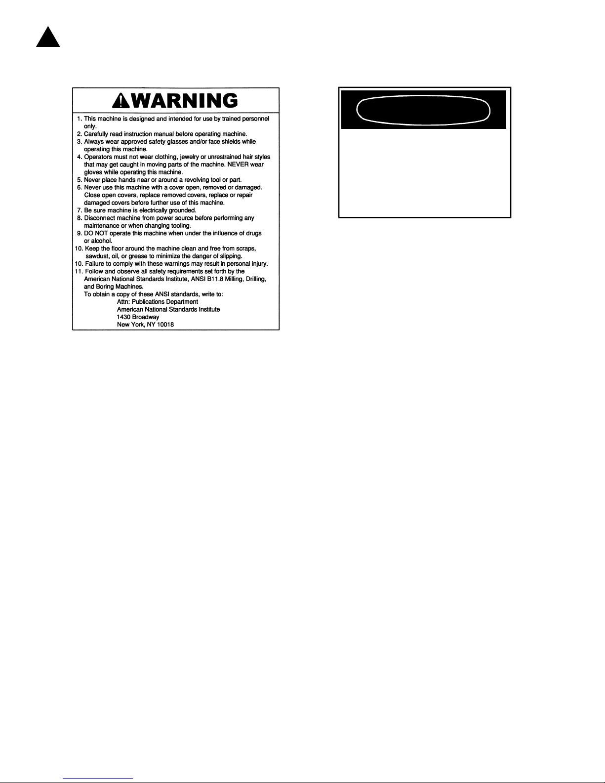
Read, understand and follow the safety and operating instructions found in this manual. Know the limita-
tions and hazards associated with a 1200HD Drill Press. A safety rules decal is installed on the belt guard of
this machine to serve as a reminder of basic safety practice.
Electrical Grounding. Make certain that the machine frame is electrically grounded and that a grounding
lead is included in the incoming electrical service. In cases where a cord and plug are used, make certain that
the grounding lug connects to a suitable ground. Follow the grounding procedure indicated by the National
Electric Code.
Eye Safety . Wear an approved safety face shield, goggles or glasses to protect eyes when operating the drill
press.
Personal Protection. Before operating the machine, remove tie, rings, watch and other jewelry and roll up
sleeves above the elbow. Remove all outer loose clothing and confine long hair . Protective type footwear
should be worn. Hearing protectors should be used where noise exceeds the level of exposure allowed in
Section 1910.95 of the OSHA regulations. Do not wear gloves.
Work Area. Keep the floor around the machine clean and free of tools, tooling, stock scrap and other foreign
material, and oil, grease or coolant to minimize the danger of tripping or slipping. Be sure the table is free of
chips, tools and everything else not required for the task to be performed. Powermatic recommends the use
of anti-skid floor strips on the floor area where the operator normally stands and that each machine's work
area be marked off. Make certain the work area is well lighted and ventilated. Provide for adequate work
space around the machine.
Guards. Keep all machine guards in place at all times when the machine is in use. Do not operate the
machine with the guard off.
Do Not Overreach. Maintain a balanced stance and keep your body under control at all times.
Maintain Tools in Top Condition. Keep tools sharp and clean for safe and best performance. Dull tools can
increase the feed force required and can result in burning the stock or seizing up,causing the work to be
pulled free from its holding device. Dull or improperly sharpened drills will not produce a straight hole.
Use the Proper Speed and Feed. A table is provided in the instruction manual as a guide in selecting the
correct speed and feed rate for a variety of materials. For materials not shown, consult the material supplier for
correct speed and feed rate. Adjust speed on variable speed models only with the power on. On step cone
models, make sure power is off and the spindle has come to a complete stop before opening the access door
to change speeds.
Never Drill Freehand. Always block or clamp the work piece. A drill bit or tap can seize up causing the work
piece, jig, or fixture to rotate with the spindle and can cause serious injury .
Remove Key Chucks. When a key chuck is used, remove it immediately after using it to lock or unlock a
tool in the chuck. If it is not removed, starting the spindle can cause it to be thrown off the chuck and could
result in serious injury .
Hand Safety . Keep hands away from the spindle when the machine is under power. Never clear chips when
the spindle is under power and never use the hands to clear chips; use a brush or chip rake. Chips are razor
sharp and can cause serious injury . Do Not Change Tools with the Spindle Rotating Under Power.
Spindle Rotation. Be sure the rotation of the spindle is correct for the tool being used.
Machine Adjustments. Make all machine adjustment s with power off except speed on a variable speed
model or feed rate on machine equipped with power feed.
4
Page 5

Machine Capacity. Do not attempt to use the machine beyond its stated capacity or for operations requiring
more than the rated horsepower of the motor. This type use will reduce the productive life of the machine and
could cause the breakage of parts which could result in personal injury.
Avoid Accident al St arting. Make certain the motor switch is in the "off" position before connecting power to
the machine.
Careless Acts. Give the work you are doing your undivided attention. Looking around,carrying on a conversation, and "horseplay" are careless acts that can result in serious injury .
Job Completion. If the operator leaves the machine area for any reason, the drill press should be turned off
and the spindle come to a complete stop before he departs. In addition, if the operation is complete, he
should clean the machine and work area. Never clean the machine with power on and never clean chips with
the hands; use a brush or chip rake.
Disconnect Machine before performing any service or maintenance and when changing tools.
Replacement Parts. Use only Powermatic or factory authorized replacement parts and accessories; other-
wise, the drill press warranty and guarantee will be null and void.
Misuse. Do not use the 1200HD Drill Press for other than its intended use. If used for other purposes,
Powermatic disclaims any real or implied warranty and holds itself harmless for any injury that may result
from the use. Do not equip a 1200HD Drill Press with a motor larger than 2 horsepower nor with a motor with
a speed greater than 1800 rpm unless specifically authorized to do so in writing by Powermatic.
If you are not thoroughly familiar with the operation of drill presses, obtain advice from your supervisor ,
instructor or other qualified person.
Drugs, alcohol, medication. Do not operate this machine while under the influence of drugs, alcohol, or any
medication.
Health hazards. Some dust created by power sanding, sawing, grinding, drilling and other construction
activities contains chemicals known to cause cancer, birth defects or other reproductive harm. Some
examples of these chemicals are:
* Lead from lead-based paint.
* Crystalline silica from bricks and cement and other masonry products.
* Arsenic and chromium from chemically-treated lumber.
Your risk from these exposures varies, depending on how often you do this type of work. To reduce your
exposure to these chemicals, work in a well-ventilated area, and work with approved safety equipment, such
as those dust masks that are specifically designed to filter out microscopic particles.
Familiarize yourself with the following safety notices used in this manual:
!
CAUTION: (This means that if precautions are not heeded, it may result in minor or moderate injury
and/or possible machine damage)
!
WARNING: (This means that if precautions are not heeded, it could result in serious injury or
possibly even death).
5
Page 6
C
F
!
SAFETY
Familiarize yourself with the location of these safety decals on your drill press.
DANGER
HEAD WILL FALL IF UNCLAMPED
WITH THE SAFETY COLLAR LOOSE.
MAKE SURE SAFETY COLLAR IS
LOCKED TO COLUMN BEFORE
UNCLAMPING HEAD WITH COLUMN
LAMP SCREWS. SEE INSTRUCTIONS
OR PROPER SPIN DLE HEAD RAISING
AND LOWERING.
3408259
3408211
SPECIFICATIONS (Model 1200HD Drill Press)
Spindle Travel.........................................................................................................................................6"
Quill Diameter................................................................................................................................... 2-3/4"
Column Diameter .............................................................................................................................4-1/2"
Column Wall Thickness ....................................................................................................................... 1/2"
Column Length ..................................................................................................................................... 66"
Table Working Surface
Production Table............................................................................................................ 15-1/2" x 18"
Base Working Surface...................................................................................................13-1/2" x 18"
Drilling Capacity (Cast Iron) ..............................................................................................................1-1/2"
Tapping Capacity (Cast Iron) .................................................................................................................. 1"
Drilling Capacity (Steel) .................................................................................................................... 1-1/4"
Tapping Capacity (Steel)......................................................................................................................3/4"
Throat Depth ............................................................................................. Drills to center of 20" diameter
Spindle Speeds:
Electronic V ariable S peed Model
Low Range ......................................................................................................................50-500 rpm
High Range .................................................................................................................200-1820 rpm
Height (overall) .....................................................................................................................................75"
Front to Rear ..................................................................................................................................33-1/2"
Weight .........................................................................................................................................606 lbs
Motor (horsepower) ............................................................................................................................ 2 hp
6
Page 7
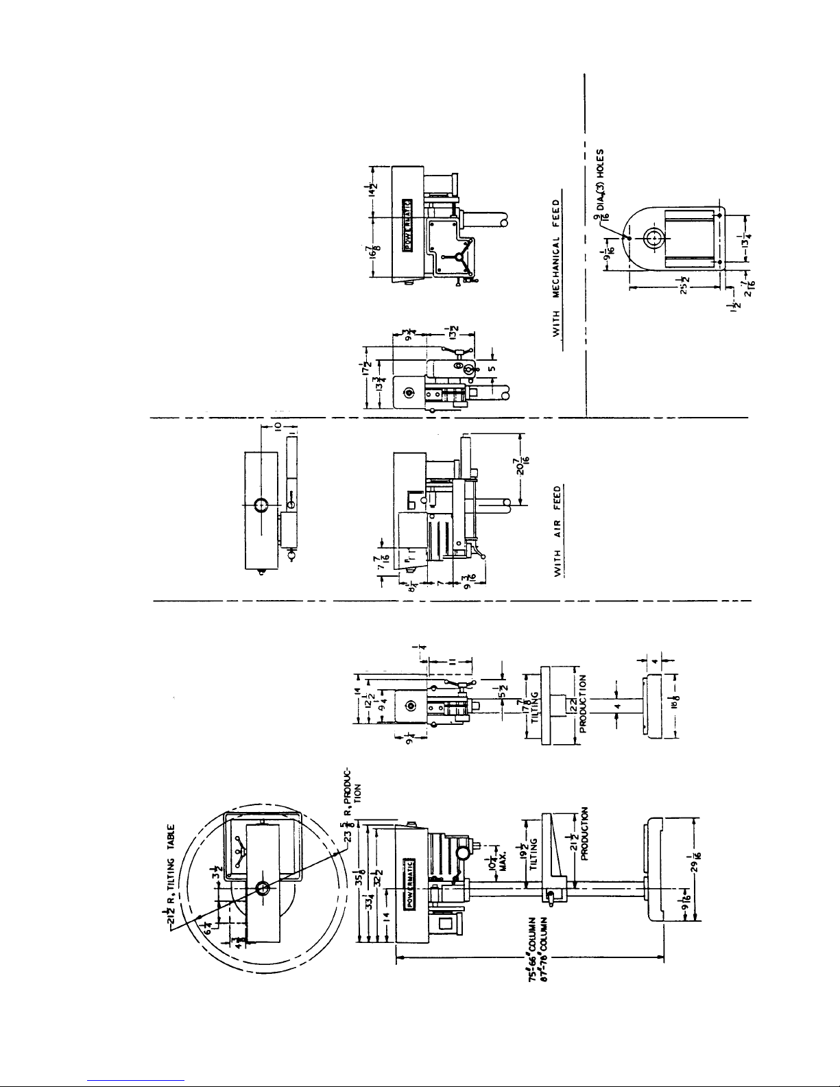
DIMENSIONAL DRAWINGS (Model 1200HD Drill Press)
FIGURE 1
7
Page 8
INSTALLATION, MAINTENANCE AND ADJUSTMENTS
RECEIVING
Remove drill press from shipping container and
check for damage. Report any damage to the
carrier and to your distributor immediately . Attach
accessories shipped with drill press, then clean
protective coating from table, column, base and
spindle with a good commercial solvent. Read
instruction manual thoroughly for assembly alignment, maintenance and safety instructions.
INSTALLATION
Mount machine on a solid foundation and lag to the
floor through holes provided in base of drill press.
The head and table of the machine have been
lowered on the column for convenience in packaging.
1. Using a crane and sling with blocks to prevent
damage to the guard; place a sling under the
head near the column on the spindle side.
2. Loosen the two binders clamping the head to
the column and raise the head to the desired
height. Move the safety collar to a position
under the head by loosening the two set
screws, sliding the collar up, and relocking
setscrews.
3. Remove the sling and clamp the head in
position.
4. Using the crane and sling, unlock the table
binder and raise the table height enough to
install the table raising rack.
5. Install the rack by placing it in the notched
area in the lower collar and driving the roll pin
through the hole in the rack and through both
ears on the collar .
6. Position the rack to engage the table raising
gearing and lower the table until the rack
engages the rack pinion.
7. Lower the crane to put slack in the sling,
engage the table raising lever and lower the
table on to the rack. Visually align the table
with the base, lock the table binder and
remove the sling.
SPINDLE TABLE MODELS
In the case of spindle table models, the legs are not
attached to the table, they are packed sep arately.
To assemble the legs to the spindle table, carefully
support machine on forklift tines or other temporary
supports and bolt legs securely into position. It is
imperative that a spindle table be carefully leveled.
Use a precision level, and adjust the level using the
jackscrews provided in the legs. Lag machine to
floor through holes provided in leveling screws (3/8"
dia. lag screws).
QUILL ADJUSTMENT
Lateral play or bellmouthing can develop between
the quill and head casting bands due to wear. To
compensate for wear between the quill and head,
proceed as follows:
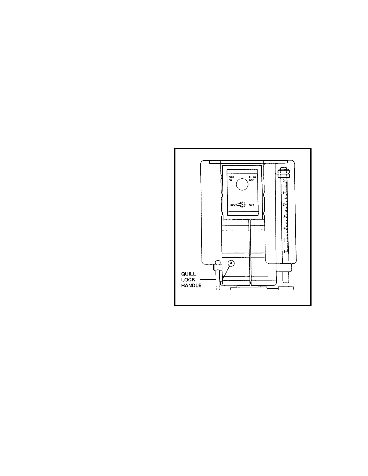
1. Be sure quill lock handle (Figure 2) is loose.
2. Squeeze slotted head casting together slightly
by tightening bolt (A). Apply just enough
pressure to compensate for wear but do not
restrict free motion down or return.
FIGURE 2
Quill Fit Up Adjustment
QUILL RETURN SPRING ADJUSTMENT
Spring tension for return of spindle, after hole
drilling, has been pre-set at the factory. No further
adjustment should be attempted unless absolutely
necessary. Adjustment will probably be required if a
multiple spindle drilling or tapping head is used. If
adjustment is necessary, loosen lock screw (A)
(Figure 3) while holding quill spring housing (B). Do
not allow the housing to turn in your hand or spring
will unwind. Turn entire housing assembly clockwise the number of turns necessary to cause the
quill to return to its up position. (NOTE: The flat of
the spring housing pilot is lined up with the spring
loading hole on the body of the spring housing.)
8
Page 9
Reset lockscrew (A), make sure point of screw mates
to flat on the housing journal.
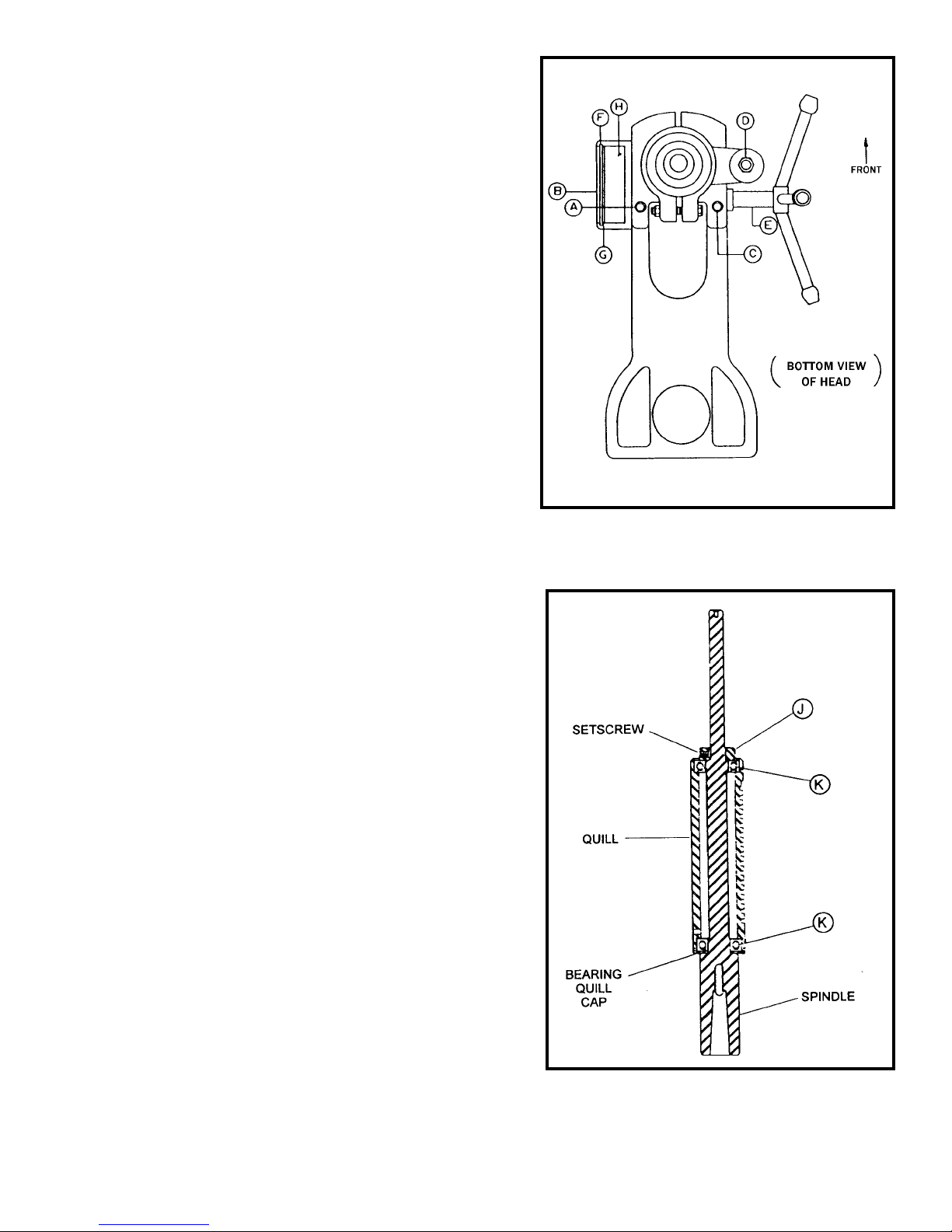
REPLACING SPINDLES ON QUILL
ASSEMBLY
To change the quill assembly for any reason, proceed
as follows:
1. Hold quill return spring housing (B) in left hand
(Figure 3) and loosen lockscrew (A). Let spring
unwind slowly , by allowing cam to turn in hand.
2. Loosen setscrew (C) and remove nut (D) on
bottom of depth stop rod. Unscrew and remove
depth stop.
3. Hold quill assembly and remove the turret pinion
shaft (E). Entire quill assembly will slide out of
head.
To change spindles, follow the above steps, then
(Figure 4):
1. Loosen setscrew in collar (J). To reach this
screw , insert a 5/32" hex head wrench.
2. With a hard rubber mallet or block of wood, tap
spline end of spindle. The spindle, with bearing
(K), will come out of quill.
3. Use an arbor press to remove bearing (K).
4. To replace spindle, reverse above procedure.
5. When replacing collar (J), remove all end play
from spindle.
6. When replacing quill in head casting, rotate
spindle, if necessary , to engage spline in pulley
driver.
7. Remove lock ring (F) and cover plate (G)
(Figure 3) from spring housing and make
certain tongue on return spring is properly
inserted in slotted end of pinion shaft. Replace
cover and adjust spring tension as instructed
under heading "QUILL RETURN SPRING
ADJUSTMENT."
FIGURE 3
Quill Removal
LUBRICATIONS
All ball bearings in your Powermatic drill press are
sealed for life, requiring no lubrication. Points requiring lubrication are:
1. Internal spline drive assembly . Keep this area
well lubricated with a good grade non-hardening
grease, such as Fiske Company "Lubriplate."
Insert grease in the hole at the top of spindle
pulley spline driver. Lube twice yearly.
2. A light film of oil applied to the quill and column
will reduce wear, prevent rust and assure ease
of operation.
3. Quill return spring should receive oil (SAE 20)
once yearly . Remove cover plate and apply
oil with squirt can or small brush.
FIGURE 4
Spindle Assembly
9
Page 10
4. IMPORTANT: The hub area of variable speed
pulleys should be oiled with a light lubricant
such as SAE 10W or automatic transmission
oil every 90 days.
5. Apply Lubriplate to quill pinion every 90 days.
6. Occasional dressing of belt with spray can
type belt dressing or parafin wax will promote
longer belt life and quieter operation.
NOTE: Use extreme care when performing
this operation and keep hands clear of pinch
points. When using parafin bar , do this only
by turning the sheaves by hand. DO NOT
apply with motor running.
7. When equipped with mechanical power feed
unit, periodically coat the gears with a good
open gear lubricant.
DRILL PRESS OPERATIONS
Familiarize yourself with all operating controls
before attempting use of this machine.
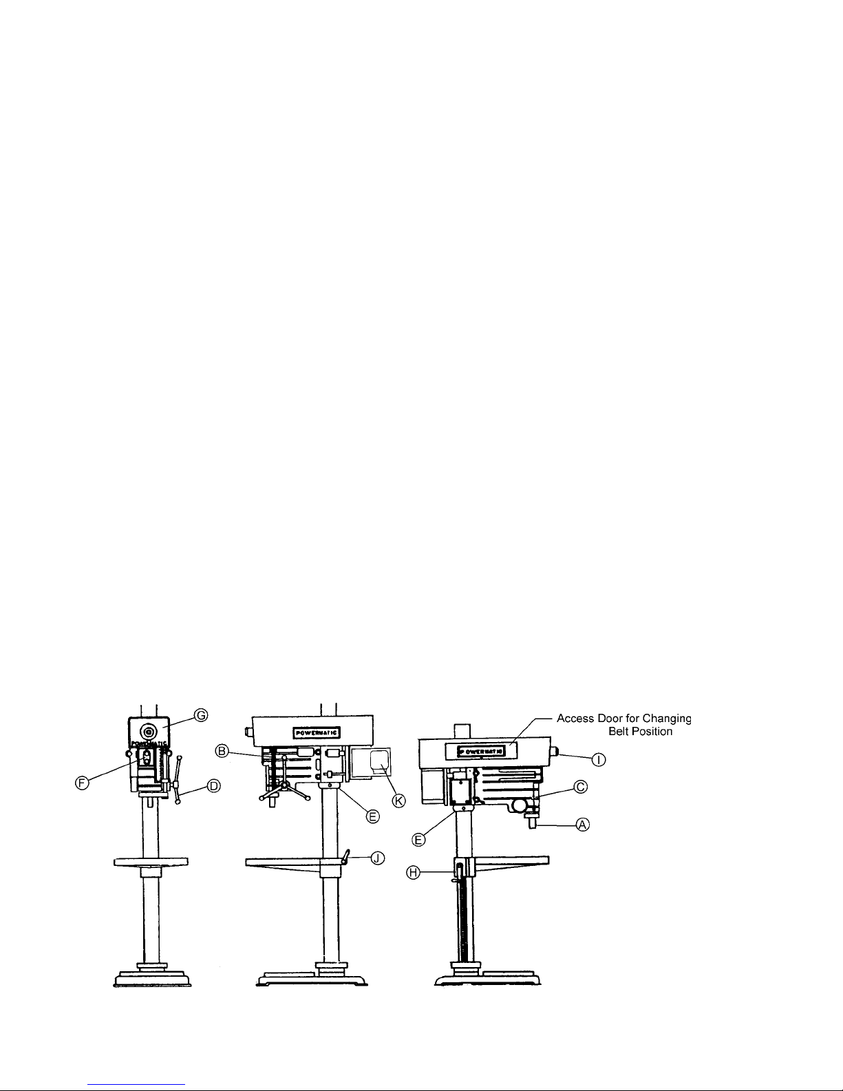
CONTROLS (see Figure 5)
1. The spindle (A) in this machine has a No. 3
Morse Taper.
2. A depth stop rod (B) is provided to control hole
depth and to prevent drilling through material into
table surfaces.
3. A quill lock (C) is located on the left side of the
head and is used to hold quill at any position.
4. The turret handle (D) is used to lower the
spindle and quill a total depth of 6"
5. A safety collar (E) is provided to prevent head
from falling when locks are released.
6. Starting switch (F) is mounted on the front of
drill press head within easy reach of the operator.
7. A speed selection chart (G) is located on the
front of the head. This chart is to provide assistance in determining proper drill speed.
8. On all 1200HD models, a knob (I) is used to
change speed.
9. On production table models, binder (J) locks
the table to the column and handle (H) is used to
raise and lower the table.
10. The model 1200HD is provided with an ACinverter (K) which is pre-programmed from the
factory and requires no changing or adjustment.
OPERATING TIPS
1. Determine drill size, inspect for sharpness,
insert and lock securely in chuck or Morse taper .
2. Arrange at this point to protect table surface
from drill breakthrough. A piece of scrap material
under the workpiece will prevent marring table
surface and eliminate splintering at breakthrough
point. Lock table securely to prevent movement.
3. Prevent the work from being torn from
operator's hand, by always securing the workpiece,
jig, fixture, or holding device to table by clamping or
blocking on the table. DO NOT use the column as a
stop. Clamp all light workpieces, jigs, fixtures, or
holding devices to the table to prevent them from
being picked up as the quill returns.
4. Select the proper RPM for the tool being used,
the material being machined, the operations to be
performed, and other conditions as indicated. (See
Tables 1A, 1B, 2, and 3 on pages 25 thru 28 for
recommendations.) If drill press is the step pulley
type, raise door and set drive belt in proper ration
position. If the machine is a variable speed model,
turn machine on the turn control cam to proper
speed. (NEVER attempt speed adjustment of
variable speed machines unless machine is running.) Turn machine off.
10
FIGURE 5
Page 11

5. Set depth stop for desired hole depth. Fine
adjustment is made by turning the fine adjustment
collar directly under pointer on depth rod. Use
upper jam nut to lock stop setting position.
6. Start coolant, if coolant is being used.
7. Turn spindle on and begin drilling operation.
As the breakthrough point is reached, always slow
feed rate down slightly to assist in elimination of
burring underside of workpiece and to help prevent
a sudden break through which can cause the drill to
grab and pull the workpiece free of its clamping
device.
8. Perform all operations with a minimum
extension of the quill. Adjust table or head position
rather than using excessive quill travel.
9. On tilting table models be sure to block the
part or holding fixture from sliding off the table
when it is used tilted at an angle. In addition, be
sure the table is clamped.
INVERTER DRIVE SYSTEM
The 1200HD Drill Press utilizes the latest technology in A.C. inverter drives to provide the infinitely
variable spindle speeds. The inverter controls the
speed of the motor by varying the frequency of the
voltage supplied to the motor . The inverter provides
an acceleration ramp that eliminates the shock of
normal across-the-line starting. Also a braking
feature eliminates long coasting periods when the
drill press is turned off.
the ON position when the power is connected, the
inverter will trip out. If this happens, disconnect
power, turn switch OFF, wait thirty seconds and
then reconnect power.
NOTE: If there is a power outage while operating
the 1200HD Drill Press, turn the switch to the OFF
position, disconnect power source, wait thirty
seconds then reconnect power source and resume
normal operation.
FOOT SWITCH OPERATION
(OPTIONAL)
The optional foot switch (Figure 6) is used only for
reversing the spindle in tapping operations.
Before using the foot switch, place the control
switch in the FWD position. When performing a
tapping operation and the tap needs to be reversed
or retracted out of a hole, press the foot switch and
hold it down. The spindle will ramp down and
immediately reverse direction. Once the tap has
completely exited or retracted from the hole,
release the foot switch and the spindle will ramp
down and immediately return to forward rotation.
The 2 HP Baldor motor is wound with "Inverter
Spike Resistant" magnet wire to give extended
motor life when used with inverter drives. The
motor is also specially balanced to reduce noise
and minimize vibration.
The A.C. Inverter does not require any programming; it is pre-programmed from the factory . The
buttons on the face of the inverter should NEVER
be pushed at anytime. Use ONLY the controls on
the front of the head assembly .
POWER CONNECTION - ELECTRONIC
V ARIABLE SPEED
The 1200HD Drill Press will operate on single or
three phase 230V or 460V , depending on inverter,
without any adjustments or programming. For
single phase power connect hot leads to R and S,
and for three phase power connect hot leads to R,
S and T as shown in the wiring diagram on page 22.
Remember to always connect the ground lead.
Before connecting to the power source make sure
the ON/OFF switch is in the OFF position and turn
the speed dial counterclockwise. If the switch is in
FIGURE 6
11
Page 12

PARTS LIST: Production & Tilting Table with Table Raising Rack (1200HD)
No. Part No. Description Quantity
2298013 Elevating Gear Box Housing Assembly (Items 1 thru 15) ........................................1
1 6624006 Groove Pin, 1/4 x 2-3/4 Lg.........................................................................................
2 3268201 Nylon Handle ........................................................................................................... 1
3 6715132 Round Head Screw, 5/16-18 x 1/2 ...........................................................................3
4 6861201 Flat Washer, 5/16.....................................................................................................3
5 3268005 Elevating Handle, D-21............................................................................................1
6 3741211 Flat Shaft Spacer, 1/2 ..............................................................................................1
7 6064001 Thrust Bearing, Nice 605 .........................................................................................1
8 6626040 Spring Pin, 1/4 x 1-1/4 .............................................................................................1
9 3237013 Pinion Gear..............................................................................................................1
10 3237002 Worm Gear..............................................................................................................1
1 1 3237001 Spur Gear ................................................................................................................1
12 6714004 Socket Set Screw, 1/4-20 x 1/4 ................................................................................2
13 3388015 Square Key, 3/16 x 3/16 x 2-1/4 ...............................................................................1
14 3701004 Gear Shaft ...............................................................................................................1
15 3298017 Gear Box Housing ...................................................................................................1
2797026 Production Table Assembly (Items 16 thru 19).........................................................1
16 3797030 Production Table ......................................................................................................1
17 3728010 Table Locking Sleeve...............................................................................................1
18 3773012 Table Locking Stud ..................................................................................................1
19 3528001 Table Stud Lock Nut.................................................................................................1
2645002 Table Raising Rack Assembly (Items 20 thru 26)..................................................... 1
20 3096040 Bearing Elevating Rack Collar .................................................................................1
21 6715118 Half Dog Point Socket Set Screw, 5/16-18 x 3/4 ......................................................2
22 6515001 Hex Nut, 5/16-18......................................................................................................2
23 3046003 Thrust Collar Bearing...............................................................................................1
24 6054002 Steel Ball Bearing, 3/8 ...........................................................................................41
25 6626033 Spring Pin, 3/16 x 2.................................................................................................. 1
26 3650005 Gear Rack, 24 .........................................................................................................1
27 6718056 Cup Point Socket Set Screw, 1/2-13 x 3/4 ...............................................................2
28 3598023 Protector Plug, 7/16 x 3/16 ......................................................................................4
29 6718055 Cup Point Socket Set Screw, 1/2-13 x 1/2 ...............................................................4
30 3042037 Drill Press Base .......................................................................................................1
31 6517006 Hex Jam Nut, 7/16-14..............................................................................................2
32 3838008 Table Locking Bevel Washer....................................................................................1
33 3268008 Table Locking Handle ..............................................................................................1
34 6638004 Pipe Plug, 1/2-14 ..................................................................................................... 1
35 3096039 Column Collar..........................................................................................................1
36 3098004 Floor Model Column ................................................................................................1
37 3104014 Head & Table Cover.................................................................................................1
38 6716038 Hex Head Cap Screw, 3/8-16 x 1/2 ..........................................................................3
39 6716042 Hex Head Cap Screw, 3/8-16 x 3.............................................................................3
40 2797028 Tilting T able Assembly (not shown).......................................................................... 1
12
Page 13

Production & Tilting Table with TABLE RAISING RACK
13
Page 14

PARTS LIST: Electronic Variable Speed Assembly (1200HD)
No. Part No. Description Quantity
2387006 Step Cone Sheave Kit Assembly (Items 1 thru 52).......................................................1
2144004 Drive Spline Sheave Assembly (Items 1 thru 6) ............................................................1
1 6060054 Ball Bearing, NTN ........................................................................................................ 2
3 6807136 Sheave - HTD Spindle .................................................................................................. 1
4 6715013 Socket Set Screw, 5/16-18 x 3/8 ................................................................................. 2
5 3388102 Square Key, 3/8 x 1-3/4 ............................................................................................... 1
6 3749133 Spline Drive Shaft.........................................................................................................1
2298005 Countershaft Housing Assembly (Items 7 thru 14)........................................................ 1
7 3298032 V/S Shaft Housing .......................................................................................................1
8 6060010 Ball Bearing, Fafnir 205PP...........................................................................................2
9 3706005 V/S Drive Shaft ............................................................................................................ 1
10 3388019 Square Key 3/16 x 3/16 x 3-11/16................................................................................1
1 1 6670005 Retaining Ring, Truarc No. 5100-100............................................................................1
12 6811326 Steel Arbor Spacer, 1 x 1-1/2 x .062............................................................................. 1
13 6807137 Sheave - HTD Countershaft ..........................................................................................1
14 6714004 Socket Set Screw, 1/4-20 x 1/4 ................................................................................... 1
2042021 Step Cone Tilting Motor Base (Items 15 thru 27)..........................................................1
15 6716114 Hex Head Cap Screw, 3/8-16 x 2-3/4 ...........................................................................1
16 6813068 Spring, 9/16 x 2 ...........................................................................................................1
17 6861301 Flat Washer, 3/8.......................................................................................................... 1
18 6715016 Cup Point Socket Set Screw, 5/16-18 x 5/16 ...............................................................5
19 3670031 Motor Base Handle Rod............................................................................................... 1
20 3268007 Tilting Handle...............................................................................................................1
21 3076011 Motor Base Handle Cam..............................................................................................1
22 3042057 Step Cone Motor Base.................................................................................................1
23 6516002 Hex Lock Nut, 3/8-16...................................................................................................1
24 3711004 Tilting Motor Base Shaft ..............................................................................................1
25 6622002 Cotter Pin, 1/8 x 1 ....................................................................................................... 1
26 3042056 Motor Mounting Base ..................................................................................................1
27 3670032 Tilting Motor Base Rod ................................................................................................2
2250061 Step Cone Belt Guard Assembly (Items 28 thru 31) ..................................................... 1
28 2136034 Step Cone Door Guard Assembly (W eldment) .............................................................1
29 6710034 Round Head Screw, #10-24 x 1/2.................................................................................4
30 6510001 Hex Nut, No. 10-24 ......................................................................................................4
31 2250165 Guard Assembly ..........................................................................................................1
32 6760046 Round Head Screw, #10-32 x 3/8.................................................................................1
33 6430017 Knob............................................................................................................................ 1
34 6458002 Rubber Molding ...........................................................................................................1
35 6514014 Self Retaining Nut........................................................................................................1
36 6714127 Hex Head Cap Screw, 1/4-20 x 1/2 ..............................................................................1
37 3063246 Upper Spindle Bearing Bracket ....................................................................................1
38 3595271 Safety Plate................................................................................................................. 1
39 6714154 Round Head Screw, 1/4-20 x 1/4..................................................................................2
40 6861200 Lock Washer, 5/16 ......................................................................................................2
41 6715032 Hex Head Screw, 5/16-18 x 1 ......................................................................................2
42 3767211 Guard Mounting Strap.................................................................................................. 2
43 6715033 Hex Head Cap Screw, 5/16-18 x 1/2 ............................................................................ 4
44 6861401 Flat Washer , 7/16........................................................................................................2
45 6717017 Hex Head Cap Screw, 7/16-14 x 1 ............................................................................... 2
46 6077230 Belt, HTD 720-8M-3 ................................................................................................... 10
47 6077229 V-Motor Belt, 3VX450 ..................................................................................................1
49 6714004 Socket Set Screw, 1/4-20 x 1/4 ................................................................................... 1
50 6716009 Cup Point Socket Set Screw, 3/8-16 x 1/2...................................................................2
51 3719191 Step Cone Sheave .......................................................................................................1
14
Page 15

PARTS LIST: Electronic Variable Speed Assembly (1200HD)
No. Part No. Description Quantity
52 6715016 Cup Point Socket Set Screw, 5/16-18 x 5/16 ...............................................................1
54 3312343 Powermatic Logo Label (one not shown)......................................................................2
55 3408259 Warning Label (not shown) ..........................................................................................1
56 3330368 Instruction Plate 1200HD .............................................................................................1
58 3719190 Step Cone Sheave .......................................................................................................1
59 6715016 Cup Point Socket Set Screw, 5/16-18 x 5/16 ...............................................................1
60 6715180 Hex Washer Head Cap Screw , 5/16-18 x 5/8 ...............................................................4
61 6471603 Electric Motor, 2 HP, 3 Ph, 1800 RPM, 230/460V , 145T, TEFC....................................1
62 6399016 Inverter, 230V............................................................................................................... 1
63 6399014 Inverter, 460V............................................................................................................... 1
64 3064737 Inverter Mounting Bracket ............................................................................................ 1
65 6716038 Screw, 3/8 ...................................................................................................................2
66 6760092 Screw, #10-32 x 1/2..................................................................................................... 6
67 6083021 Contact Block.............................................................................................................. 1
68 6821492 Fwd/Rev Switch ...........................................................................................................1
69 6643000 Control Pot .................................................................................................................. 1
70 3578353 Control Panel...............................................................................................................1
71 6821491 Push/Pull Switch .........................................................................................................1
72 6860800 Washer........................................................................................................................1
73 6601000 "O" Ring ...................................................................................................................... 2
74 6430054 Control Panel Knob...................................................................................................... 1
75 6095272 Strain Relief Connector Bushing...................................................................................1
76 6095271 Strain Relief Bushing ...................................................................................................1
77 6860802 Lock Washer, #10 .......................................................................................................2
78 4709259 Rubber Bumper ...........................................................................................................2
79 6861100 Lock Washer, 1/4 ........................................................................................................2
80 6122038 Clamp.......................................................................................................................... 2
81 3755258 Spring .......................................................................................................................... 1
82 3595381 Plate (Stiffening) ..........................................................................................................2
84 3408211 Danger Label (not shown) ............................................................................................1
85 6706035 Round Head Machine Screw, #6-32 x 1/4 .................................................................... 2
86 6295733 Brake Resistor (230V) .................................................................................................1
87 6661023 Brake Resistor (460V) .................................................................................................1
88 6860802 Lock Washer #10 ........................................................................................................ 6
15
Page 16

Electronic Variable Speed Assembly (1200HD)
16
Page 17

PARTS LIST: Spindle Table, Legs & Column Mounting Bracket Assy.
(1200HD)
No. Part No. Description Quantity
1 3098005 Bench Model Column for Spindle Table ...................................................................1
2 6718009 Hex Head Cap Screw, for Spindle Table ..................................................................4
3 6718025 Hex Head Cap Screw, 1/2-13 x 2-1/2 for Spindle Table ...........................................2
4 3064078 Column Mounting Bracket for Spindle Table ............................................................1
5 3797015 1 Spindle Table with T-Slots.....................................................................................1
6 6638004 Pipe Plug, 1/2-14 NPT .............................................................................................1
7 6718015 Hex Head Cap Screw, 1/2-13 x 1 for Spindle Table .................................................4
8 2423003 Table End Leg Assembly (Weldment) for Spindle Table ..........................................2
9 3694006 Table Leveling Hex Head Bolt for Spindle T able.......................................................4
17
Page 18

PARTS LIST: Head Raising Assembly (1200HD)
No. Part No. Description Quantity
2298016 Head Raising Mechanism (Items 1 thru 15) 1 Spindle Table....................................1
1 3237002 Gear ........................................................................................................................1
2 3237001 Gear ........................................................................................................................1
3 6714004 Socket Set Screw, 1/4-20 x 1/4 ................................................................................2
4 3388015 Square Key, 3/16 x 3/16 x 2-1/4 ...............................................................................1
5 3701004 Gear Shaft ...............................................................................................................1
6 6861201 Flat Washer, 5/16.....................................................................................................3
7 6715132 Round Head Screw, 5/16-18 x 1/2 ...........................................................................3
8 3237013 Pinion Gear..............................................................................................................1
9 6626040 Spring Pin, 1/4-1-1/4................................................................................................1
10 6064001 Thrust Bearing, Nice 605 .........................................................................................1
11 6861602 Flat Shaft Spacer, 1/2 ..............................................................................................1
12 3268005 Elevating Handle, D-21............................................................................................1
13 3268201 Nylon Machine Handle.............................................................................................1
14 6624006 Groove Pin, 1/4 x 2-3/4............................................................................................ 1
15 3298018 Elevating Gear Box Housing....................................................................................1
2645001 Head Raising Rack Assembly (Items 16 thru 22) 1 Spindle Table ...........................1
16 3650004 Gear Rack, 13-1/4 ...................................................................................................1
17 3096040 Elevating Rack Bearing Collar .................................................................................1
18 6626033 Spring Pin, 3/16 x 2.................................................................................................. 1
19 6515001 Hex Nut, 5/16-18......................................................................................................2
20 6715118 Half Dog Point Socket Set Screw, 5/16-18 x 3/4 ......................................................2
21 6054002 Steel Bearing Ball, 3/8............................................................................................ 41
22 3046003 Thrust Bearing Collar ................................................................................................1
23 3098005 Bench Model Column, 1 S pindle ...............................................................................1
24 3096039 Column Collar, 1 S pindle...........................................................................................1
25 3598023 Protector Plug, 7/16 x 3/16, 1 Spindle ...................................................................... 4
26 6718055 Cup Point Socket Set Screw , 1/2-13 x 1/2, 1 Spindle ...............................................4
29 6716042 Hex Head Cap Screw , 3/8-16 x 3, 1 Spindle .............................................................3
18
Page 19

Head Raising Assembly (1200HD)
19
Page 20

PARTS LIST: Head Assembly (1200HD)
No. Part No. Description Quantity
2268006 Turret Handle Assembly (Items 1 and 2)..................................................................1
1 3406206 Phenolic Knob..........................................................................................................3
2 3670025 Knob Handle............................................................................................................3
2277016 Head Assembly (Items 3 thru 39) ............................................................................1
2686003 Pinion Hub Assembly (Items 3 thru 6)......................................................................1
3 3301003 T urret Hub ...............................................................................................................1
4 6715016 Cup Point Socket Screw, 5/16-18 x 5/16 ..................................................................1
5 3388004 Key, 3/16 x 3/16 x 1 .................................................................................................1
6 3586026 Quill Operating Pinion..............................................................................................1
2670026 Depth Adjustment Rod Assembly (Items 7 thru 1 1, 40 & 41) ................................... 1
7 3526094 Depth Adjustment Lock Nut-Plain............................................................................1
8 3526093 Graduated Depth Adjustment Nut............................................................................1
9 6626035 Spring Pin, 3/16 x 5/8...............................................................................................1
10 3670102 Depth Adjustment Rod.............................................................................................1
1 1 3528005 Hex Nut.................................................................................................................... 2
2640019 No. 3 Mounting Quill Assembly (Items 12 thru 17)...................................................1
12 3078006 Quill Bearing Cap.....................................................................................................1
13 6060014 Ball Bearing, SKF No. 6206 2RS ............................................................................. 2
14 3640017 Sliding Quill..............................................................................................................1
15 3096214 Spindle Collar ..........................................................................................................1
16 6715015 Socket Set Cup Point Screw, 5/16-18 x 1/4 .............................................................1
17 3749110 No. 3 Mounting Spindle............................................................................................1
2695009 Quill Locking Screw Assembly (Items 18 thru 20)....................................................1
18 3268002 Handle .....................................................................................................................1
19 3695010 Quill Lock Screw......................................................................................................1
20 3406016 Knob ........................................................................................................................1
2695015 Head Locking Screw Assembly (Items 21 thru 23) ..................................................1
21 3406016 Knob ........................................................................................................................1
22 3695002 Head Locking Screw................................................................................................1
23 3268002 Handle .....................................................................................................................1
24 3448014 Plain Head Locking Sleeve ......................................................................................2
25 6670071 Retaining Ring, RS-275 ............................................................................................2
26 3104010 S pring Cover .............................................................................................................1
27 6813026 Clock Spring.............................................................................................................1
28 3298280 Spring Housing .........................................................................................................1
29 6716114 Hex Head Screw , 3/8-16 x 2-3/4 ............................................................................... 1
30 6714199 Round Head Screw, 1/4-20 x 1-1/4 ...........................................................................1
31 3092012 Switch Wire Clamp...................................................................................................1
32 3448015 Threaded Head Locking Sleeve.................................................................................2
33 3277013 Head ........................................................................................................................1
34 6718038 Half Dog Point Socket Set Screw, 1/2-13 x 1-1/4......................................................2
35 6518008 Hex Nut, 1/2-13 ........................................................................................................ 2
36 6804005 "O" Ring Seal, Rubber..............................................................................................1
37 6515001 Hex Nut, 5/16-18 ......................................................................................................1
38 6715044 Hex Head Screw , 5/16-18 x 2 ................................................................................... 1
39 3936021 Quill Y oke................................................................................................................. 1
40 3119012 Inches Scale Decal ..................................................................................................1
41 3119013 Metric Scale Decal ................................................................................................... 1
42 3104014 Head & T able Cover , 1 S pindle .................................................................................. 1
43 6716038 Hex Head Cap Screw, 3/8-16 x 1/2, 1 S pindle ..........................................................3
20
Page 21

Head Assembly (1200HD)
21
Page 22

ELECTRICAL SCHEMATIC 1200HD
22
Page 23

ELECTRICAL SCHEMATIC 1200HD (when used with Reversing Foot Switch)
23
Page 24

Trouble-Shooting for Model 1200HD Drill Press
PROBLEM POSSIBLE CAUSE SOLUTION
Excessive vibration. 1. Improper belt tension. 1. Adjust belt tension.
2. Uneven belt wear (hard spots). 2. Replace belt.
3. Motor or spindle pulley out-of-balance. 3. Balance or repair problem pulley
4. Bad motor. 4. Replace motor .
Motor stalls 1. Over feeding. 1. Reduce feed rate.
2. Dull drill. 2. Sharpen drill and keep sharp.
3. V/S belt riding on inner cone. 3. Re-adjust V/S belt.
4. Motor not building up to running speed. 4. Replace or repair motor . Check fuses
in all three legs on three phase motor
and replace if necessary.
5. Bad motor. 5. Replace motor .
Noisy operation. 1. Excessive vibration. 1. Check remedy under excessive
vibration.
2. Improper quill adjustment. 2. Adjust quill (refer to paragraph on quill
adjustment).
3. Noisy spline. 3. Lubricate spline.
4. Noisy motor . 4. Check motor bearings or for loose
motor fan.
Drill or tool heats up or 1. Excessive speed. 1. Reduce speed.
burns work. 2. Chips not clearing. 2. Use pecking operation to clear chips.
3. Dull tool. 3. Sharpen tool or replace.
4. Feed rate too slow . 4. Increase feed enough to clear chips.
5. Rotation of drill incorrect. 5. Reverse motor rotation (refer to motor
wiring diagram).
6. Failure to use cutting oil or coolant 6. Use cutting oil or coolant on steel.
(on steel).
Drill leads off. 1. No drill spot. 1. Center punch or center drill work-
piece.
2. Cutting lips on drill off center . 2. Regrind drill.
3. Quill loose in head. 3. Tighten quill (refer to quill adjustment).
4. Bearing play. 4. Check bearings and reseat or replace
if necessary .
Excessive drill runout or 1. Bent drill. 1. Replace drill. Do not attempt to
wobble. straighten.
2. Bearing play. 2. Replace or reseat bearings.
3. Drill not seated properly in chuck. 3. Loosen, reseat and tighten chuck.
Work or Fixture comes 1. Failure to clamp workpiece or work 1. Clamp workpiece or work holding
holding device to table. device to table surface.
24
Page 25

TABLE 1A: DRILLING FEEDS - SPEED - HORSEPOWER REQUIRED
CAST IRON
FT. PER MIN. 250 FT. 150 FT. 300 FT. 80 FT. 100 FT. 80 FT. 80 FT. 40 FT.
INCHES INCHES RPM RPM RPM RPM RPM RPM RPM RPM
1/16 0.003 15279 9167 18320 4889 6111 4889 4889 2445
3/32 0.0035 10186 6111 12212 3262 4077 3262 3262 1628
1/8 0.004 7639 4583 9160 2445 3056 2445 2445 1222
5/32 0.0045 6111 3667 7328 1956 2445 1956 1956 976
3/16 0.005 5093 3056 6106 1630 2037 1630 1630 815
7/32 0.0055 4365 2619 5234 1398 1747 1398 1398 698
1/4 0.006 3820 2292 4575 1222 1528 1222 1222 611
9/32 0.0065 3395 2037 4071 1087 1359 1087 1087 542
5/16 0.007 3056 1833 3660 978 1222 978 978 489
11/32 0.0075 2778 1667 3330 889 1111 889 889 444
3/8 0.008 2546 1528 3050 815 1019 815 815 407
13/32 0.0085 2350 1410 2818 752 940 752 752 376
7/16 0.009 2183 1310 2614 698 873 698 698 349
15/32 0.0095 2037 1222 2442 652 815 652 652 326
1/2 0.01 1910 1146 2287 611 764 611 611 306
17/32 0.0102 1798 1079 2157 575 719 575 575 288
9/16 0.0105 1698 1019 2035 543 679 543 543 271
19/32 0.0107 1608 965 1930 515 643 515 515 257
5/8 0.011 1528 917 1830 489 611 489 489 244
21/32 0.0112 1456 873 1746 466 582 466 466 233
11/16 0.0115 1389 833 1665 444 556 444 444 222
23/32 0.0117 1329 797 1594 425 532 425 425 213
3/4 0.012 1273 764 1525 407 509 407 407 204
25/32 0.0122 1222 733 1467 391 489 391 391 196
13/16 0.0125 1175 705 1409 376 470 376 376 188
7/8 0.013 1091 655 1307 349 436 349 349 175
15/16 0.0135 1019 611 1221 326 407 326 326 163
1 0.014 955 573 1143 306 382 306 306 153
SIZE OF
DRILL
FEED PER
REVOLU-
TION
BRONZE
BRASS
COPPER
ALUMINUM
MALLE-
ABLETION
MACHINE
SURFACE
SCALE
SURFACE
DEEP
HOLES
STEEL
CASTING
25
Page 26

TABLE 1B: DRILLING FEEDS - SPEED - HORSEPOWER REQUIRED
STEEL CAST IRON STEEL
SIZE OF
DRILL
INCHES INCHES RPM RPM RPM RPM RPM HP HP HP HP
1/16 0.003 2445 3056 3667 4278 4889 0.07 0.0043 0.18 0.0076
3/32 0.0035 1628 2039 2446 2852 3262 0.11 0.0044 0.27 0.0079
1/8 0.004 1222 1528 1833 2139 2445 0.14 0.0045 0.36 0.0081
5/32 0.0045 976 1223 1467 1711 1956 0.18 0.0046 0.45 0.0084
3/16 0.005 815 1019 1222 1426 1630 0.22 0.0047 0.54 0.0087
7/32 0.0055 698 874 1048 1222 1398 0.25 0.0049 0.63 0.0089
1/4 0.006 611 764 917 1070 1222 0.29 0.005 0.72 0.0092
9/32 0.0065 542 680 815 950 1087 0.33 0.0051 0.81 0.0095
5/16 0.007 489 611 733 856 978 0.37 0.0053 0.89 0.0097
11/32 0.0075 444 555 667 778 889 0.4 0.0054 0.98 0.01
3/8 0.008 407 509 611 713 815 0.44 0.0055 1.07 0.0102
13/32 0.0085 376 470 564 658 752 0.47 0.0056 1.16 0.0104
7/16 0.009 349 437 524 611 698 0.5 0.0057 1.25 0.0106
15/32 0.0095 326 408 489 570 652 0.54 0.0058 1.34 0.0107
1/2 0.01 306 382 458 535 611 0.57 0.0059 1.43 0.0109
17/32 0.0102 288 360 431 503 575 0.6 0.006 1.51 0.0111
9/16 0.0105 271 340 407 475 543 0.64 0.0061 1.6 0.0112
19/32 0.0107 257 322 382 450 515 0.68 0.0062 1.69 0.0114
5/8 0.011 244 306 367 428 489 0.72 0.00624 1.78 0.0115
21/32 0.0112 233 291 349 407 466 0.75 0.0063 1.87 0.0117
11/16 0.0115 222 278 333 389 444 0.79 0.0064 1.96 0.0118
23/32 0.0117 213 266 319 372 425 0.83 0.0065 2.05 0.012
3/4 0.012 204 255 306 357 407 0.87 0.0066 2.14 0.0121
25/32 0.0122 196 245 293 342 391 0.9 0.00665 2.22 0.0122
13/16 0.0125 188 235 282 329 376 0.94 0.0067 2.31 0.0123
7/8 0.013 175 218 262 306 349 1.01 0.0068 2.49 0.0126
15/16 0.0135 163 204 244 285 326 1.09 0.0069 2.67 0.0128
FEED PER
REVOLU-
TION
FT. PER MIN. 40 FT. 50 FT. 60 FT. 70 FT. 80 FT.
1 0.014 153 191 229 267 306 1.16 0.007 2.85 0.013
VERY
HARD
BRINELL
402-444
HARD
BRINELL
302-387
MEDIUM
BRINELL
202-293
SOFT
BRINELL
101-196
DEAD
SOFT
BRINELL
UNDER 100
CUTTING
HP
FEED
HP
CUTTING
HP
FEED
HP
26
Page 27

TABLE 2: REAMING SPEEDS - HIGH SPEED STEEL TOOLS
MATERIALS - RPM
STEEL
BRASS
1/8 0.004 1222 1528 1833 2139 2445 0.14 0.0045 0.36 0.0081
1/4 0.006 611 764 917 1070 1222 0.29 0.005 0.72 0.0092
3/8 0.008 407 509 611 713 815 0.44 0.0055 1.07 0.0102
1/2 0.01 306 382 458 535 611 0.57 0.0059 1.43 0.0109
5/8 0.011 244 306 367 428 489 0.72 0.00624 1.78 0.0115
3/4 0.012 204 255 306 357 407 0.87 0.0066 2.14 0.0121
7/8 0.013 175 218 262 306 349 1.01 0.0068 2.49 0.0126
1 0.014 153 191 229 267 306 1.16 0.007 2.85 0.013
NOTE: For Carbide Reamers Use 3 Times Charts Speeds
325 100 50 50 40 30 45 55 65 110
NOTE: For Carbide Spotfacers Use 4 Times Chart Values
BRONZE
Counterboring & Spotfacing - High Speed Steel Tools - Surface Ft./Min.
MALLE-
ABLE
IRON
CAST
IRON
CLASS 30
STEEL
CASTING
VERY
HARD
BRINELL
400-425
HARD
BRINELL
300-375
MEDIUM
BRINELL
225-300
SOFT
BRINELL
100-200
DEAD
SOFT
BRINELL
UNDER 100
27
Page 28

TABLE 3: TAPPING AND THREADING FORMULA FOR CALCULATING
HORSEPOWER REQUIREMENTS
PPV = Power Pitch V alue
SFM = Surface Feet Per Minute
M = Material Factor
TD = Tool Dullness Factor
HP = Horsepower
RPM = Revolutions Per Minute
TAPPING AND THREADING FACTORS CHART
Threads per inch Power Pitch Value* PPV
32 0.002
27 0.0034
24 0.004
20 0.006
18 0.007
16 0.009
14 0.011
13 0.012
12 0.014
11-1/2 0.015
11 0.016
10 0.02
9 0.025
8 0.03
7 0.035
6 0.04
Multiply PPV by 2.2 for Double or Taper Pipe Threads
TD - Use (1.5 Factor) for Tool Dullness
HP = PPV x SFM x M x TD
28
MATERIAL AND SPEED FACTORS CHART
MATERIAL FACTOR - M SPEED - S.F.M.
Aluminum 0.5 100
Bakelite 0.6 75
Brass 0.6 90
Bronze 0.6 50
Bronze Mang. 1 40
Copper 0.5 80
Alum. Die Cast 0.6 80
Fiber 0.5 75
Zinc Die Cast 0.6 80
Cast Iron 0.6 70
Mall eable Iron 0.6 45
Magnesium 0.5 100
St eel Cast 1.4 35
St eel Fr. Mach. 1 50
St eel Chromium 1.7 30
St eel Alloy 1.7 25
St eel Stainless 1.7 20
REVOLUTIONS PER MINUTE CALCULATION
R.P.M. = 3.82 X S.F.M. + Dia.
Page 29

29
Page 30

30
Page 31

T o order parts or reach our service dep artment, please call our toll-free number between 8:00 a.m. and 4:30 p.m.
(CST), Monday through Friday . Having the Model Number and Serial Number of your machine available when
you call will allow us to serve you quickly and accurately . Locating the stock number of the part(s) required from
your parts manual will also expedite your order .
Phone No.: (800) 248-0144
Fax No. (800) 274-6840
If you are calling from Canada, please call 800-238-4746
E-mail: powermatic@wmhtoolgroup.com
Website: www .wmhtoolgroup.com
31
Page 32

10/03
WMH T ool Group
427 Sanford Road
LaVergne, TN 37086
Phone: (800) 248-0144
Fax: (800) 274-6840
E-mail: powermatic@wmhtoolgroup.com
Website: www.wmhtoolgroup.com
C
POWERMA TIC ALL RIGHTS RESERVED
 Loading...