

15" DRILL PRESS
Models 1150A & 1150HD
Instruction Manual & Parts List
M-0460256
(800) 248-0144
www.powermatic.com

This manual has been prepared for the owner and operators of a Powermatic Model 1150A or
1150HD, 15" Drill Press. Its purpose, aside from machine operation, is to promote safety through
the use of accepted correct operating and maintenance procedures. Completely read the safety
and maintenance instructions before operating or servicing the machine. To obtain maximum
life and efficiency from your drill press and to aid in using the machine safely, read this manual
thoroughly and follow all instructions carefully.
Warranty & Service
The JET Group warrants every product it sells. If one of our tools needs service or repair, one of our Authorized Repair Stations located throughout the United States can give you quick service.
In most cases, any one of these JET Group Repair Stations can authorize warranty repair, assist you in
obtaining parts, or perform routine maintenance and major repair on your JET, Performax or Powermatic
tools.
For the name of an Authorized Repair Station in your area, please call 1-800-274-6848.
More Information
Remember, the JET Group is consistently adding new products to the line. For complete, up-to-date product
information, check with your local JET Group distributor.
JET Group Warranty
The JET Group (including Performax and Powermatic brands) makes every effort to assure that its products
meet high quality and durability standards and warrants to the original retail consumer/purchaser of our
products that each product be free from defects in materials and workmanship as follow: 1 YEAR LIMITED
WARRANTY ON ALL PRODUCTS UNLESS SPECIFIED OTHERWISE. This Warranty does not apply to
defects due directly or indirectly to misuse, abuse, negligence or accidents, normal wear-and-tear, repair or
alterations outside our facilities, or to a lack of maintenance.
THE JET GROUP LIMITS ALL IMPLIED WARRANTIES TO THE PERIOD SPECIFIED ABOVE, FROM THE
DATE THE PRODUCT WAS PURCHASED AT RETAIL. EXCEPT AS STATED HEREIN, ANY IMPLIED
WARRANTIES OR MERCHANTIBILITY AND FITNESS ARE EXCLUDED. SOME STATES DO NOT
ALLOW LIMITATIONS ON HOW LONG THE IMPLIED WARRANTY LASTS, SO THE ABOVE LIMITATION
MAY NOT APPLY TO YOU. THE JET GROUP SHALL IN NO EVENT BE LIABLE FOR DEATH, INJURIES
TO PERSONS OR PROPERTY, OR FOR INCIDENTAL, CONTINGENT, SPECIAL, OR CONSEQUENTIAL
DAMAGES ARISING FROM THE USE OF OUR PRODUCTS. SOME STATES DO NOT ALLOW THE
EXCLUSION OR LIMITATION OF INCIDENTAL OR CONSEQUENTIAL DAMAGES, SO THE ABOVE
LIMITATION OR EXCLUSION MAY NOT APPLY TO YOU.
To take advantage of this warranty, the product or part must be returned for examination, postage prepaid, to
an Authorized Repair Station designated by our office. Proof of purchase date and an explanation of the
complaint must accompany the merchandise. If our inspection discloses a defect, we will either repair or
replace the product, or refund the purchase price if we cannot readily and quickly provide a repair or replacement, if you are willing to accept a refund. We will return repaired product or replacement at JET's expense,
but if it is determined there is no defect, or that the defect resulted from causes not within the scope of JET's
warranty, then the user must bear the cost of storing and returning the product. This warranty gives you
specific legal rights; you may also have other rights which vary from state to state.
The JET Group sells through distributors only. Members of the JET Group reserve the right to effect at any
time, without prior notice, those alterations to parts, fittings, and accessory equipment which they may deem
necessary for any reason whatsoever.

TABLE OF CONTENTS
Safety:
Rules .........................................................................................................................................4-5
Decals .......................................................................................................................................... 6
Dimensional Drawings .......................................................................................................................... 7
Specifications:
1150A ........................................................................................................................................... 8
1150HD ........................................................................................................................................ 9
Installation, Adjustments & Maintenance
Receiving.................................................................................................................................... 10
Installation .................................................................................................................................. 10
Multiple Spindle Models .............................................................................................................. 10
Motor Installation ........................................................................................................................ 10
Changing Speeds ....................................................................................................................... 12
Installing Chuck .......................................................................................................................... 12
Quill Adjustment ......................................................................................................................... 12
Quill Return Spring Adjustment ..................................................................................................14
Replacing Spindles on Quill Assembly........................................................................................ 14
Lubrication .................................................................................................................................. 14
Inverter Drive System (1150HD only).......................................................................................... 14
Power Connection - Electronic Variable Speed ........................................................................... 16
Foot Switch Operation (Optional - Model 1150HD only).............................................................. 16
Drill Press Operations:
Controls ...................................................................................................................................... 17
Operating Tips ............................................................................................................................ 17
Trouble-shooting................................................................................................................................. 18
Table 1A: Drilling Feeds - Speed - Horsepower Required................................................................... 19
Table 1B: Drilling Feeds - Speed - Horsepower Required................................................................... 20
Table 2: Reaming Speeds - High Speed Steel Tools - Materials - RPM .............................................. 21
Table 3: Tapping and Threading Formula for Calculating Horsepower Requirements......................... 22
Parts Lists & Exploded Views:
Head Assembly (1 Spring Keychuck & 1 Spring Taper Socket) ............................................... 23-25
Stepcone Assembly (1150A only) ........................................................................................... 26-27
Electronic Variable Speed Assembly (1150HD only) ............................................................... 28-29
Production Table & Base Assembly ....................................................................................... 30-31
Tilting Table Assembly............................................................................................................ 32-33
Foot Feed Assembly (Optional - 1150HD only) ....................................................................... 34-35
Head Raising Assembly (Optional) ......................................................................................... 36-37
Electrical Schematics:
1150A only, Manual and Magnetic starter .................................................................................... 38
1150HD only................................................................................................................................39
1150HD only (when used with Reversing Foot Switch) ................................................................. 40

!
SAFETY RULES
As with all machines, there is a certain amount of hazard involved with the use of this drill press. Use the
machine with the respect and caution demanded where safety precautions are concerned. When normal safety
precautions are overlooked or ignored, personal injury to the operator can result.
Read, understand and follow the safety and operating instructions found in this manual. Know the limitations
and hazards associated with an 1150A or 1150HD Drill Press.
Electrical grounding. Make certain that the machine frame is electrically grounded and that a grounding lead is
included in the incoming electrical service. In cases where a cord and plug are used, make certain that the
grounding lug connects to a suitable ground. Follow the grounding procedure indicated by the National Electric
Code.
Eye Safety. Wear an approved safety face shield, goggles or glasses to protect eyes. (NOTE: Common
eyeglasses are not safety glasses.)
Personal Protection. Before operating the machine, remove tie, rings, watch and other jewelry and roll up
sleeves above the elbow. Remove all loose outer clothing and confine long hair. Protective type footwear should
be worn. Where the noise exceeds the level of exposure allowed in Section 1910.95 of the OSHA regulations,
use hearing protective devices. Do not wear gloves.
Work Area. Keep the floor around the machine clean and free of tools, tooling, stock scrap and other foreign
material, and oil, grease or coolant to minimize the danger of tripping or slipping. Be sure the table is free of
chips, tools and everything else not required for the task to be performed. Powermatic recommends the use of
anti-skid floor strips on the floor area where the operator normally stands and that each machine's work area be
marked off. Make certain the work area is well lighted and ventilated. Provide for adequate work space around
the machine.
Guards. Keep all machine guards in place at all times when the machine is in use. Do not operate the machine
with the guard off.
Operator Position. Maintain a balanced stance and keep your body under control at all times. Do not overreach.
Careless Acts: Give the work you are doing your undivided attention. Looking around, carrying on a conversation, and "horseplay" are careless acts that can result in serious injury.
Maintain Tools in Top Condition. Keep tools sharp and clean for safe and best performance. Dull tools can
increase the feed force required and can result in burning the stock or seizing up, causing the work to be pulled
free from its holding device. Dull or improperly sharpened drills will not produce a straight hole.
Use the Proper Speed and Feed. Tables are provided on pages 17-20 as a guide in selecting the correct speed
and feed rate for a variety of materials. For materials not shown, consult the material supplier for correct speed
and feed rate. Adjust speed on variable speed models only with the power on. On step cone models, make sure
power is off and the spindle has come to a complete stop before opening the access door to change speeds.
Never Drill Freehand. Always block or clamp the work piece. A drill bit or tap can seize up causing the work
piece, jig, or fixture to rotate with the spindle and can cause serious injury.
Remove Key Chucks: When a key chuck is used, remove it immediately after using it to lock or unlock a tool in
the chuck. If it is not removed, starting the spindle can cause it to be thrown off the chuck and could result in
serious injury.
Hand Safety: Keep hands away from the spindle when the machine is under power. Never clear chips when the
spindle is under power and never use the hands to clear chips; use a brush or chip rake. Chips are razor sharp
and can cause serious injury. Do Not Change Tools with the Spindle Rotating Under Power.
4

Spindle Rotation: Be sure the rotation of the spindle is correct for the tool being used.
Machine Adjustments: Make all machine adjustments with power off except speed on a variable speed model.
Machine Capacity: Do not attempt to use the machine beyond its stated capacity or for operations requiring
more than the rated horsepower of the motor. This type use will reduce the productive life of the machine and
could cause the breakage of parts which could result in personal injury.
Avoid Accidental Starting: Make certain the motor switch is in the "off" position before connecting power to the
machine.
Job Completion: If the operator leaves the machine area for any reason, the drill press should be turned off and
the spindle come to a complete stop before he departs. In addition, if the operation is complete, he should clean
the machine and work area. Never clean the machine with power on and never clean chips with the hands; use
a brush or chip rake.
Disconnect Machine: Before performing any service or maintenance and when changing tools.
Replacement Parts: Use only Powermatic or factory authorized replacement parts and accessories; otherwise,
the drill press warranty and guarantee will be null and void.
Misuse: Do not use the 1150A Drill Press for other than its intended use. If used for other purposes, Powermatic
disclaims any real or implied warranty and holds itself harmless for any injury that may result from the use. Do
not equip an 1150A Drill Press with a motor larger than 1 horsepower nor with a motor with a speed greater than
4800 rpm unless specifically authorized to do so in writing by Powermatic.
Drugs, alcohol, medication. Do not operate this machine while under the influence of drugs, acohol, or any
medication.
Health Hazards. Some dust created by power sanding, sawing, grinding, drilling and other construction
activities contains chemicals known to cause cancer, birth defects or other reproductive harm. Some
examples of these chemicals are:
* Lead from lead-based paint.
* Crystalline silica from bricks and cement and other masonry products.
* Arsenic and chromium from chemically-treated lumber.
Your risk from these exposures varies, depending on how often you do this type of work. To reduce your
exposure to these chemicals, work in a well-ventilated area, and work with approved safety equipment, such
as those dust masks that are specifically designed to filter out microscopic particles.
Familiarize yourself with the following safety notices used in this manual:
!
CAUTION: (This means that if precautions are not heeded, it may result in minor or moderate injury
and/or possible machine damage)
!
WARNING: (This means that if precautions are not heeded, it could result in serious injury or
possibly even death).
5

!
SAFETY
Familiarize yourself with the location of these safety decals on your drill press.
'$1*(5
+($':,//)$//,)81&/$03('
3330284
:,7+7+(6$)(7<&2//$5/226(
0$.(685( 6$ )( 7< &2/ /$ 5, 6
/2&.('72&2/801%()25(
81&/$0 3,1* +($ ': ,7 + &2/8 01
&/$036&5(:66((,16758&7,216
)253523(56 3,1'/ (+($ ' 5 $, 6,1*
$1'/2:(5,1*
SAFETY RULES
3408211
CAREFULLY READ INSTRUCTION MANUAL BEFORE OPERATING
MACHINE.
DO NOT OPERATE WITHOUT ALL GUARDS AND COVERS IN POSITION.
BE SURE MACHINE IS ELECTRICALLY GROUNDED.
REMOVE OR FASTEN LOOSE ARTICLES OF CLOTHING SUCH AS
NECKTIES, ETC. CONFINE HAIR.
REMOVE JEWELRY SUCH AS FINGER RINGS, WATCHES, BRACELETS,
ETC.
USE SAFETY FACE SHIELD, GOGGLES, OR GLASSES TO PROTECT
EYES AND OTHER PERSONAL SAFETY EQUIPMENT AS REQUIRED.
STOP MACHINE BEFORE MAKING ADJUSTMENTS OR CLEANING CHIPS
FROM WORK AREA.
KEEP THE FLOOR AROUND THE MACHINE CLEAN AND FREE FROM
SCRAPS, SAWDUST, OIL OR GREASE TO MINIMIZE THE DANGER OF
SLIPPING.
TO AVOID SERIOUS INJURY, SECURELY CLAMP OR BLOCK WORK
PIECE, JIG, OR FIXTURE TO PREVENT ROTATION SHOULD DRILL SEIZEUP OCCUR.
6
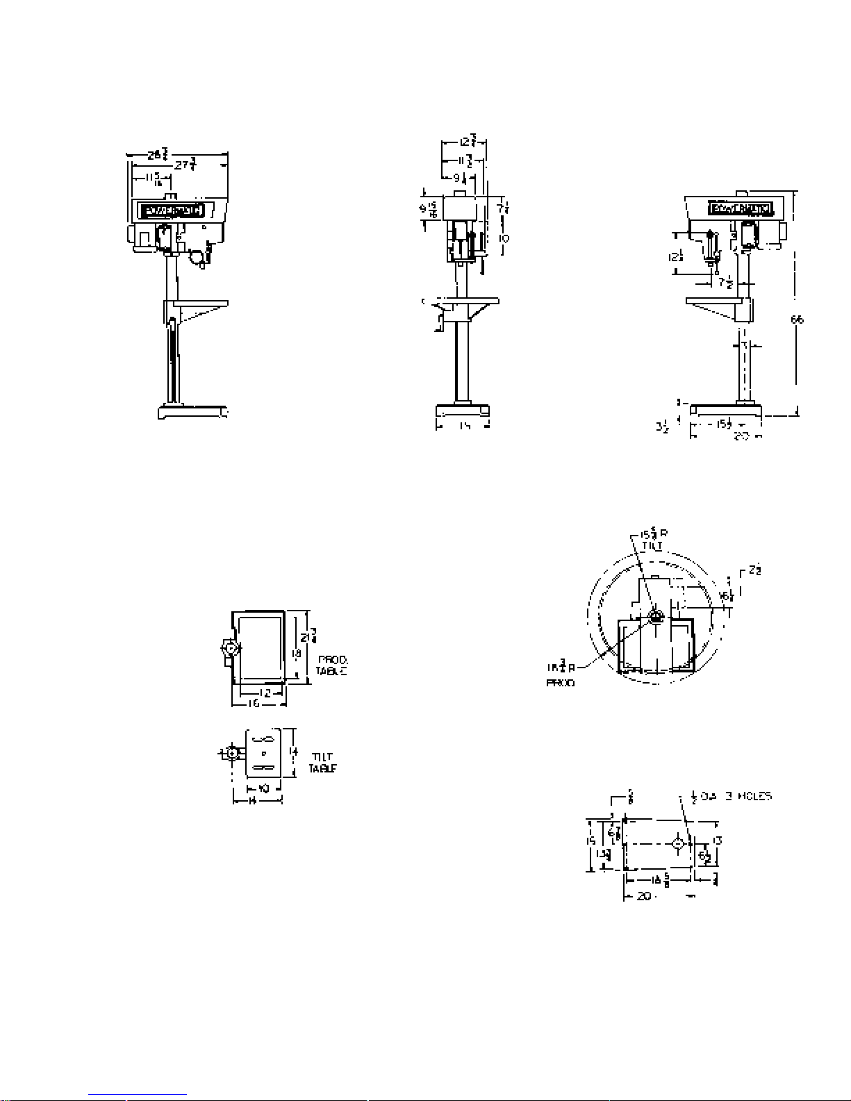
DIMENSIONAL DRAWINGS (1150A and 1150HD)
7

SPECIFICATIONS 1150A Drill Press
Spindle ................................................... steel, 10-spline, #33 Jacobs Taper with 0"-1/2" capacity chuck
Spindle Travel......................................................................................................................................... 6"
Quill Diameter................................................................................................................................. 2-3/16"
Column Outside Diameter ...................................................................................................................... 3"
Column Wall Thickness ..................................................................................................................... 3/16"
Column Length, Floor Model ................................................................................................................ 66"
Column Length, Bench Model .............................................................................................................. 42"
Table Working Surface:
Tilting Table ......................................................................................................................... 10" x 14"
Production Table .................................................................................................................. 12" x 18"
Base Working Surface .............................................................................................................8-1/2" x 12"
Drilling Capacity (Cast Iron) ................................................................................................................. 5/8"
Tapping Capacity (Cast Iron) ............................................................................................................... 1/2"
Drilling Capacity (Steel) ....................................................................................................................... 1/2"
Tapping Capacity (Steel)...................................................................................................................... 3/8"
Throat Depth ...................................................................................................... Drills to center of 15" dia.
Spindle Nose to:
Floor Model - Production Table 37-1/4" 47-1/4"
Floor Model - Tilting Table 41" 46-1/4"
Key Chuck to:
Floor Model - Production Table 36-3/4" 47-1/4"
Floor Model - Tilting Table 40-1/2" 46"
T-slots use Standard T-Bolts ............................................................................................................... 1/2"
Spindle Speeds:
Variable Speed Models
1800 RPM Motor.................................................................................................. 450-4800 RPM
1200 RPM Motor.................................................................................................. 300-3200 RPM
Step Pulley Models
1800 RPM Motor......................................................................... 400-840-1580-2800-5300 RPM
1200 RPM Motor......................................................................... 260-560-1050-1875-3550 RPM
Shipping Weight ............................................................................................................................ 323 lbs.
TABLE BASE
8

SPECIFICATIONS 1150HD Drill Press
Spindle; Steel .....................................................10-spline, #33 Jacobs Taper with 0"-1/2" capacity chuck
Spindle Travel......................................................................................................................................... 6"
Quill Diameter................................................................................................................................. 2-3/16"
Column Outside Diameter ...................................................................................................................... 3"
Column Wall Thickness ..................................................................................................................... 3/16"
Column Length, Floor Model ................................................................................................................ 66"
Table Working Surface:
Tilting Table ......................................................................................................................... 10" x 14"
Production Table .................................................................................................................. 12" x 18"
Base Working Surface .............................................................................................................8-1/2" x 12"
Drilling Capacity (Cast Iron) ................................................................................................................. 5/8"
Tapping Capacity (Cast Iron) ............................................................................................................... 1/2"
Drilling Capacity (Steel) ....................................................................................................................... 1/2"
Tapping Capacity (Steel)...................................................................................................................... 3/8"
Throat Depth ...................................................................................................... Drills to center of 15" dia.
Key Chuck to:
Floor Model - Production Table 36-3/4" 47-1/4"
Floor Model - Tilting Table 40-1/2" 46"
Spindle Speeds:
Electronic Variable Speed Model
Low Range............................................................................................................. 150-700 RPM
Medium Range .................................................................................................... 400-1600 RPM
High Range........................................................................................................ 1050-4200 RPM
Step Pulley Models
1800 RPM Motor......................................................................... 400-840-1580-2800-5300 RPM
1200 RPM Motor......................................................................... 260-560-1050-1875-3550 RPM
Overall height ....................................................................................................................................... 66"
Weight ........................................................................................................................................432 lbs.
Motor (horsepower)
Electronic Variable Speed .......................................................................................................... 1 HP
Step Pulley ............................................................................................................................. 3/4 HP
TABLE BASE
9

INSTALLATION, ADJUSTMENTS & MAINTENANCE
RECEIVING
Remove drill press from shipping container and check for damage. Report any damage to the carrier and to your
distributor immediately. Attach accessories shipped with drill press, then clean protective coating from table,
column, base and spindle with a good commercial solvent. Read instruction manual thoroughly for assembly
alignment, maintenance and safety instructions.
INSTALLATION
Mount machine on a solid foundation and lag to the floor through holes provided in base of drill press. The head
and table of the machine have been lowered on the column for convenience in packaging. If your drill press is
not equipped with an optional head raising assembly, you can raise the head by proceeding as follows:
1. Place a block of wood on top of table and under spindle nose. Raise table until spindle nose contacts the
block.
2. Loosen head locking handles, bumping them lightly to make certain they release.
3. Turn handle counter - clockwise (toward the operator). Head will move upward 6".
4. Lock head again with locking handles, raise table to a position just under spindle nose and repeat steps
2 through 4.
5. If the above procedure is too slow, use a minimum of three men to move head to its proper height; two
to lift head and one to perform the loosening and locking of the handles.
6. After head is at proper height, secure tightly, then slide the safety collar up and lock it in place under the
head. This will prevent the head from falling if loosened for swing drilling operations.
WARNING: The drill head will fall if the locking handles are loosened and the safety collar is not
!
secured beneath it. Always lock the safety collar after head has been positioned.
7. Visually align spindle with table and base.
MULTIPLE SPINDLE MODELS
In the case of multiple spindle models, the legs are not attached to the table, they are packed separately. To
assemble the legs to multiple spindle models, carefully support machine on forklift tines or other temporary
supports and bolt legs securely into position. The tables of multiple spindle models are at times shipped in more
than one piece. In joining table halves, use alignment pins provided before securing bolts. These pins guarantee
alignment of table surfaces. It is imperative that multiple spindle tables be carefully leveled. Use a precision level
and level using the jackscrews provided in the legs. Lag machine to floor through holes provided in legs.
MOTOR INSTALLATION
Step Pulley Models (1150A):
If your machine was ordered less motor, or if the motor is being replaced, the following instructions will
make installation easier.
a. Place motor pulley on motor shaft and insert key.
b. Raise drill press table as shown in Fig. 1. Place motor upright on table and install motor to motor
mount, using (4) 5/16-18 hex nuts. Align motor and spindle pulley and tighten motor pulley set
screws.
c. Loosen lock handle (Fig. 2) and place belt over pulleys and into lowest speed grooves. Push motor
base clamp to rear for light belt tension and turn lock screw clockwise to lock. Too much tension will
cause excessive vibration, shaft breakage, bearing noise and wear.
10
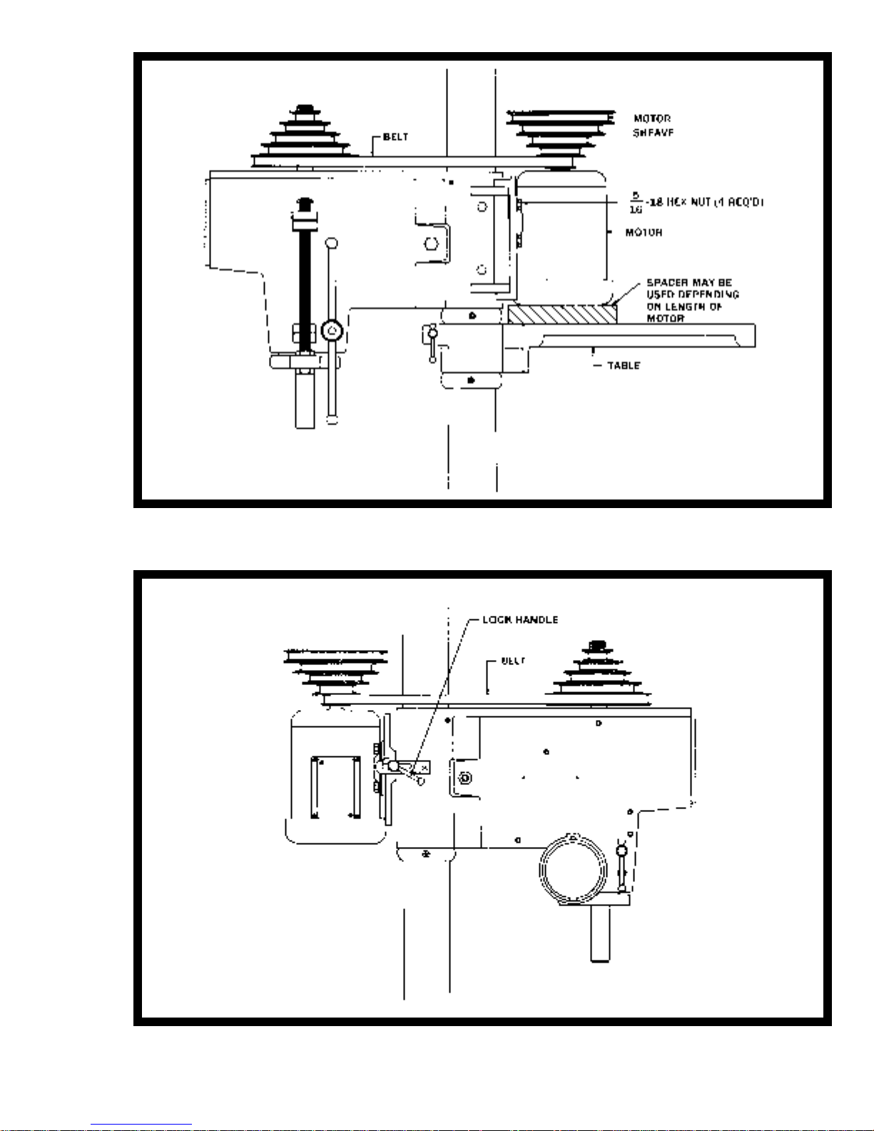
FIGURE 1
MOTOR INSTALLATION
FIGURE 2
BELT TENSIONING
11

Variable Speed Models (1150HD):
Powermatic prefers to ship all variable speed drill presses with motors installed. However, if the machine
was ordered less motor, or a motor is being replaced, the following instructions apply.
a. Remove variable speed control hub (Fig. 3), from the shaft. Then remove guard retaining screws and
lift guard from machine.
b. Raise drill press table and lock in position (Fig. 1). Place motor on table in upright position and
attach motor to motor mount, using (4) 5/16-18 hex nuts.
c. Place variable speed motor pulley on motor shaft (spring up); open pulley by placing variable
speed belt between halves and pulling outward on belt. Insert key in keyway, then tighten screws
in the bottom side of the pulley flange.
d. Before replacing guard - temporarily replace variable speed control hub (Fig. 4). Turn machine on.
The belt should be in a horizontal plane. If belt is cocked at an angle, shut off the motor, loosen
motor pulley and move on shaft until belt is level. Secure setscrew. (See section on changing speeds
for setting speed range.)
e. Remove handle - replace guard, then control hub. Machine is now ready for operation.
NOTE: The above operations are easier to perform with head raised to its maximum height (flush
with top of column) since it is easier to remove the belt guard with this position.
CHANGING SPEEDS
Speed changes on step pulley models are to be made with the machine not running - loosen motor base clamp
(Fig. 2) and pull handle toward operator. Belt is now free to move to any of the 5 speeds available. When speed
choice is made, move handle to rear for proper tension and lock the motor base.
Speed changes on variable speed models are to be made ONLY WHILE MACHINE IS RUNNING. Damage to
variable drive mechanism will result if speed is adjusted while machine is not running.
If spindle speed does not appear to match the dial speed on variable speed unit - check speed with a tachometer
and adjust by unlocking the setscrews in the upper sheave half and turning the top nut on the spline drive (see
Fig. 4) clockwise to decrease speed and counterclockwise to increase speed.
To set speeds, adjust cam to minimum RPM, adjust by means of nut on the spline driver to flush belt with outside
diameter of spindle sheave. Move motor back until belt has minimum of play. Pull out on one side of the belt. If
there is a minimum of slack, the motor and belt system are properly adjusted in this position. The upper sheave
on the spline driver has two setscrews which must be unlocked for the sheave to be moved. After adjustment
lock the setscrews bring the lock nut down against the hub of the upper sheave and bend a tab of the lockwasher
into the nut to lock its position.
INSTALLING CHUCK
1. Wipe off the No. 33 spindle taper and tapered socket in chuck body (Fig. 5) with a clean cloth. Make
sure no foreign particles are left on these surfaces which could prevent proper seating of the two parts.
2. Apply a light film of oil on the spindle taper and place chuck on end of spindle (Fig. 5). Screw chuck
collar on to the threads at end of spindle. Hold spindle pulley with one hand to keep spindle from
rotating and tighten the chuck collar with drill chuck key.
3. When removal of the chuck is required - disconnect power source. Hold top spindle pulley with one
hand and using chuck key handle, loosen chuck collar by turning counter-clockwise (Fig. 5). Continued
rotation of the collar will force the chuck off tapered spindle. NEVER attempt to drive or wedge chuck
off as damage could result to chuck, spindle nose and spindle bearings.
QUILL ADJUSTMENT
Lateral play or bellmouthing can develop between the quill and head casting bands due to wear. To compensate
for wear between the quill and head, proceed as follows:
a. Be sure quill lock handle (Fig. 6) is loose.
b. Squeeze slotted head casting together slightly by tightening bolt (A). Apply just enough pressure to compensate for wear but do not restrict free motion down or return.
12

FIGURE 3
V/S GUARD REMOVAL
FIGURE 4
V/S SPEED ADJUSTMENT
FIGURE 5
KEY CHUCK INSTALLATION
FIGURE 6
QUILL FIT UP ADJUSTMENT
13

QUILL RETURN SPRING ADJUSTMENT
Spring tension for return of the spindle, after hole drilling, has been pre-set at the factory. No further adjustment
should be attempted unless absolutely necessary. Adjustment will probably be required if a multiple spindle
drilling or tapping head is used. If adjustment is necessary, loosen lock screw (A) (Fig. 7) while holding quill
spring housing (B). DO NOT allow the housing to turn in your hand or spring will unwind.
Turn entire housing assembly clockwise the number of turns necessary to cause the quill to return to its up
position. (NOTE: The flat of the spring housing pilot is lined up with the spring loading hole on the body of the
spring housing.) Reset lockscrew (A), and make sure point of screw mates to flat on the housing journal.
REPLACING SPINDLES ON QUILL ASSEMBLY
To change the quill assembly for any reason, proceed as follows:
1. Hold quill return spring housing (B) in left hand (see Fig. 7) and loosen lockscrew (A). Let spring unwind
slowly, by allowing housing to turn in hand.
2. Loosen setscrew (C) (Fig. 6) and remove nut (D) on bottom of depth stop rod. Unscrew and remove
depth stop.
3. Lower quill assembly to the position where the turret pinion shaft can be removed (E). Entire quill
assembly will then slide out of head.
To change spindles, follow the above steps, then (Fig. 8):
1. Loosen setscrew in collar (A). To reach this screw, insert a 5/32" Allen wrench through hole (B) in top of
quill.
2. With a hard rubber mallet or block of wood, tap spline end of spindle. The spindle, with bearing (C), will
come out of the quill.
3. Use an arbor press to remove bearing (C).
4. To replace spindle, reverse above procedure.
5. When replacing collar (A), remove all end play from spindle.
6. When replacing quill in head casting, rotate spindle, if necessary, to engage spline in pulley driver.
7. If necessary, remove lock ring (F) and cover plate (G) (Fig. 7) from spring housing and make certain
tongue on return spring (H) is properly inserted in slotted end of pinion shaft. Replace cover and adjust
spring tension as instructed under heading "QUILL RETURN SPRING ADJUSTMENT."
LUBRICATION
All ball bearings in your Powermatic drill press are sealed for life, requiring no lubrication. Points requiring
lubrication are:
1. Internal spline drive assembly. Keep this area well lubricated with a good grade non-hardening grease,
such as Fiske Company "Lubriplate." Insert grease in the hole at the top of spindle pulley spline driver.
Lube twice yearly.
2. A light film of oil applied to the quill and column will reduce wear, prevent rust and assure ease of
operation.
3. Quill return spring should receive oil (SAE 20) once yearly. Remove cover plate and apply oil with squirt
can or small brush.
4. IMPORTANT: The hub area of variable speed pulleys should be coated with a DOW Corning GN Paste
or equivalent.
5. Apply Lubriplate to quill pinion every 90 days.
6. Occasional dressing of belt with spray can type belt dressing or parafin wax will promote longer belt life
and quieter operation.
NOTE: Use extreme care when performing this operation and keep hands clear of pinch points. When
using parafin bar, do this only by turning the sheaves by hand. DO NOT apply with motor running.
INVERTER DRIVE SYSTEM (1150HD only)
The 1150HD Drill Press utilizes the latest technology in A.C. inverter drives to provide infinitely variable spindle
speeds. The inverter controls the speed of the motor by varying the frequency of the voltage supplied to the
motor. The inverter provides an acceleration ramp that eliminates the shock of normal across-the-line starting.
Also a braking feature eliminates long coasting periods when the drill press is turned off.
14

FIGURE 7
QUILL REMOVAL
SPINDLE ASSEMBLY
FIGURE 8
15

The 1 HP Baldor motor is wound with "Inverter Spike Resistant" magnet wire to give extended motor life when
used with inverter drives. The motor is also specially balanced to reduce noise and minimize vibration.
The A.C. inverter does not require any programming; it is pre-programmed from the factory. The buttons on the
face of the inverter should NEVER be pushed at any time. Use ONLY the controls on the front of the head
assembly.
POWER CONNECTION - ELECTRONIC VARIABLE SPEED
The 1150HD Drill Press will operate on single or three phrase, 230V or 460V, depending on the inverter, without
any adjustments or programming. For single phase power, connect hot leads to L1 and L2. For three phrase
power, connect hot leads to L1, L2 and L3 as shown in the wiring diagram on page 39. Remember to always
connect the ground lead.
Before connecting to the power source make sure the ON/OFF switch is in the OFF position, and turn the speed
dial counterclockwise. If the switch is in the ON position when the power is connected, the inverter will trip out.
If this happens, disconnect power, turn switch OFF, wait thiry seconds and then reconnect power.
NOTE: If there is a power outage while operating the 1150HD Drill Press, turn the switch to the OFF position,
disconnect power source, wait thiry seconds then reconnect power source and resume normal operation.
FOOT SWITCH OPERATION (Optional - Model 1150HD only )
The optional foot switch is used only for reversing the spindle in tapping operations.
Before using the foot switch, place the control switch in the FWD position.
When performing a tapping operation and the tap needs to be reversed or retracted out of a hole, press the
foot switch and hold it down. The spindle will ramp down and immediately reverse direction. Once the tap has
completely exited or retracted from the hole, release the foot switch and the spindle will ramp down and
immediately return to forward rotation.
16

DRILL PRESS OPERATIONS
Familiarize yourself with all operating controls before
attempting use of this machine.
CONTROLS (see Figure 10)
1. The spindle (A) in this machine is either a No. 2
Morse Taper or a No. 33 taper type equipped with a
chuck. The key type chuck is 1/2" capacity, held to
the spindle by the taper and a threaded lock collar.
2. A depth stop rod (B) is provided to control hole
depth and to prevent drilling through material into table
surfaces.
3. A quill lock (C) is located on the left side of the
head and is used to hold quill at any position.
4. The turret handle (D) is used to lower the spindle
and quill a total depth of 6".
5. Safety collars (E) are provided to prevent head
and/or table from falling when locks are released. Be
sure collars are in place and securely locked; one
under the head and one under the tilting table. No
safety collar is required for the production table as it
is rack and pinion controlled.
6. Starting switch (F) is mounted on the front of
drill press head within easy reach of the operator.
7. A speed selection chart (G) is located on the
front of the head. This chart is to provide assistance
in determining proper drill speed.
8. The model 1150HD is provided with an AC-Inverter (H) which is pre-programmed from the factory
and requires no changing or adjustment.
OPERATING TIPS
1. Determine drill size, inspect for sharpness, insert and lock securely in chuck or Morse taper.
2. Arrange at this point to protect table surface from
drill breakthrough. A piece of scrap material under
the workpiece will prevent marring table surface and
eliminate splintering at breakthrough point. Lock table
securely to prevent movement.
3. Prevent the work from being torn from operator's
hand by always securing the workpiece, jig, fixture,
or holding device to table by clamping or blocking on
the table. DO NOT use the column as a stop. Clamp
all light workpieces, jigs, fixtures, or holding devices
to the table to prevent them from being picked up as
the quill returns.
4. Select the proper RPM for the tool being used,
the material being machined, the operations to be
performed, and other conditions as indicated. (See
Tables I, II, and III on pages 17-20 for recommendations.) If drill press is the step pulley type, raise door
and set drive belt in proper ration position. If the machine is a variable speed model, turn machine on and
turn control cam to proper speed. NEVER attempt
speed adjustment of variable speed machines unless machine is running. Turn machine off.
5. On tilting table models, be sure to block the part
or holding fixture from sliding off the table when it is
used tilted at an angle. In addition, be sure the table
is clamped.
6. Set depth stop for desired hole depth. Fine adjustment is made by turning the fine adjustment collar. Use upper collar to lock stop setting position.
7. If coolant is being used, start flow.
8. Turn machine on and begin drilling operation.
As the breakthrough point is reached, always slow
feed rate down slightly to assist in elimination of burring underside of workpiece and to help prevent a sudden break through which can cause the drill to grab
and pull the workpiece free of its clamping device.
8. Perform all operations with a minimum extension of the quill. Adjust table or head position rather
than using excessive quill travel.
FIGURE 10
17

TROUBLE SHOOTING
ELBUORTESUACELBABORPYDEMER
noitarbiVevissecxE.noisnettlebreporpmI.1
sllatSrotoMgnideefrevO.1
noitarepOysioN.noitarbivevissecxE.1
pUstaeHlooTrollirD
kroWsnruBro
.noisnettlebtsujdA.1
.)stopsdrah(raewtlebnevenU.2
.ecnalab-fo-tuoyellupeldnipsrorotoM.3
.rotomdaB.4
llirdlluD.2
.enocrenninognidirtlebS/V.3
.deepsgninnurotpugnidliubtonrotoM.4
.rotomdaB.5
.tnemtsujdalliuqreporpmI.2
.enilpsysioN.3
.rotomysioN.4
.deepsevissecxE.1
.gniraelctonspihC.2
.lootlluD.3
.wolsootetardeeF.4
.tcerrocnillirdfonoitatoR.5
no(tnaloocroliognittucesuoteruliaF.6
.)leets
.tlebecalpeR.2
.yellupmelborpecalperroecnalaB.3
.rotomecalpeR.4
.etardeefecudeR.1
.prahspeekdnallirdneprahS.2
.tlebS/Vtsujda-eR.3
sesufkcehC.rotomriaperroecalpeR.4
srotomesahpeerhtnosgeleerhtllani
.yrassecenfiecalperdna
.rotomecalpeR.5
evissecxerednuydemerkcehC.1
.noitarbiv
lliuqnonoitcesotrefer(lliuqtsujdA.2
.)tnemtsujda
.enilpsetacirbuL.3
esoolrofrosgniraebrotomkcehC.4
.nafrotom
.deepsecudeR.1
.spihcraelcotnoitarepognikcepesU.2
.ecalperrolootneprahS.3
.spihcraelcothguonedeefesaercnI.4
rotomotrefer(noitatorrotomesreveR.5
.)margaidgniriw
.leetsnotnaloocroliognittucesU.6
ffOsdaeLllirD.topsllirdoN.1
.retnecffollirdnospilgnittuC.2
.daehniesoollliuQ.3
.yalpgniraeB.4
llirDevissecxE
elbboWrotuonuR
erutxiFrokroW
roesooLsemoC
snipS
.llirddneB.1
.yalpgniraeB.2
.skcuhcniylreporpdetaestonllirD.3
krowroeceipkrowpmalcoteruliaF.1
.elbatotecivedgnidloh
.llirddnirgeR.2
.yrassecenfi
ottpmettatonoD.llirdecalpeR.1
.nethgiarts
.sgniraebtaeserroecalpeR.2
.ecafruselbatotecived
.eceipkrowllirdretnecrohcnupretneC.1
.)tnemtsujdalliuqotrefer(lliuqnethgiT.3
ecalperrotaeserdnasgniraebkcehC.4
.kcuhcnethgitdnataeser,nesooL.3
gnidlohkrowroeceipkrowpmalC.1
18

TABLE 1A: DRILLING FEEDS - SPEED - HORSEPOWER REQUIRED
NORITSAC
FEED PER
SIZE OF
DRILL
REVOLU-
TION
SEHCNISEHCNIMPRMPRMPRMPRMPRMPRMPRMPR
61/1300.09725176190238198841116988498845442
23/35300.06810111162122126237704262326238261
8/1400.093673854061954426503544254422221
23/55400.01116766382376591544265916591679
61/3500.03905650360160361730203610361518
23/75500.05634916243258931747189318931896
4/1600.00283292257542221825122212221116
23/95600.05933730217047801953178017801245
61/5700.06503338106638792221879879984
23/115700.08772766103339881111988988444
8/3800.06452825105035189101518518704
23/315800.0053201418182257049257257673
61/7900.0381201314162896378896896943
23/515900.0730222212442256518256256623
2/110.0019164117822116467116116603
23/712010.0897197017512575917575575882
61/95010.0896191015302345976345345172
23/917010.080615690391515346515515752
8/5110.082517190381984116984984442
BRONZE
BRASS
.NIMREP.TF.TF052.TF051.TF003.TF08.TF001.TF08.TF08.TF04
COPPER
ALUMINUM
MALLE-
ABLETION
MACHINE
SURFACE
SCALE
SURFACE
DEEP
HOLES
STEEL
CASTING
19

TABLE 1B: DRILLING FEEDS - SPEED - HORSEPOWER REQUIRED
LEETS
NORITSAC
SIZE OF
DRILL
FEED PER
REVOLU-
TION
.NIMREP.TF.TF04.TF05.TF06.TF07.TF08
SEHCNISEHCNIMPRMPRMPRMPRMPRPHPHPHPH
61/1300.05442650376638724988470.03400.081.06700.0
23/35300.08261930264422582262311.04400.072.09700.0
8/1400.02221825133819312544241.05400.063.01800.0
23/55400.0679322176411171659181.06400.054.04800.0
61/3500.0518910122216241036122.07400.045.07800.0
23/75500.089647884012221893152.09400.036.09800.0
4/1600.01164677190701222192.0500.027.02900.0
23/95600.0245086518059780133.01500.018.05900.0
61/5700.098411633765887973.03500.098.07900.0
23/115700.04445557668779884.04500.089.010.0
8/3800.070490511631751844.05500.070.12010.0
23/315800.067307446585625774.06500.061.14010.0
61/7900.09437344251168965.07500.052.16010.0
23/515900.062380498407525645.08500.043.17010.0
2/110.060328385453511675.09500.034.19010.0
23/712010.08820631343055756.0600.015.11110.0
61/95010.017204370457434546.01600.06.12110.0
23/917010.075222328305451586.02600.096.14110.0
8/5110.044260376382498427.042600.087.15110.0
VERY
HARD
BRINELL
402-444
HARD
BRINELL
302-387
MEDIUM
BRINELL
202-293
SOFT
BRINELL
101-196
DEAD
SOFT
BRINELL
UNDER 100
CUTTINGHPFEEDHPCUTTINGHPFEED
NORITSACLEETS
HP
20

TABLE 2: REAMING SPEEDS - HIGH SPEED STEEL TOOLS
MATERIALS - RPM
LEETS
BRASS
8/100530061002200120071046008002100910802
4/10071008001105010580230040060590401
8/30021035037007006012072034046007
2/1088004055025044061091023084025
8/5007023044014053031051052083014
BRONZE
52300105050403545556011
MALLE-
ABLE
IRON
CAST
IRON
CLASS 30
STEEL
CASTING
sdeepStrahCsemiT3esUsremaeRedibraCroF:ETON
seulaVtrahCsemiT4esUsrecaftopSedibraCroF:ETON
VERY
HARD
BRINELL
400-425
HARD
BRINELL
300-375
MEDIUM
BRINELL
225-300
.niM/.tFecafruS-slooTleetSdeepShgiH-gnicaftopS&gnirobretnuoC
SOFT
BRINELL
100-200
DEAD
SOFT
BRINELL
UNDER 100
21

TABLE 3: TAPPING AND THREADING FORMULA FOR CALCULATING
HORSEPOWER REQUIREMENTS
PPV = Power Pitch Value
SFM = Surface Feet Per Minute
M = Material Factor
TD = Tool Dullness Factor
HP = Horsepower
RPM = Revolutions Per Minute
D1@@9>71>4D8B5149>7613D?BC381BD
DXbUQTc`UbY^SX @_gUb@YdSXFQ\eU@@F
#" "
"' #$
"$ $
" &
!( '
!& )
!$ !!
!# !"
!" !$
!!!" !%
!! !&
! "
) "%
( #
' #%
& $
=e\dY`\i@@FRi""V_b4_eR\U_bDQ`Ub@Y`UDXbUQTc
D4EcU!%6QSd_bV_bD__\4e\\^Ucc
HP = PPV x SFM x M x TD
22
=1D5B91<1>4C@554613D?BC381BD
=1D5B91< 613D?B= C@554C6=
1\e]Y^e] % !
2Q[U\YdU & '%
2bQcc & )
2b_^jU & %
2b_^jU=Q^W ! $
3_``Ub % (
1\e]4YU3Qcd & (
6YRUb % '%
JY^S4YU3Qcd & (
3Qcd9b_^ & '
=Q\\UQR\U9b_^ & $%
=QW^UcYe] % !
CdUU\3Qcd !$ #%
CdUU\6b=QSX ! %
CdUU\3Xb_]Ye] !' #
CdUU\1\\_i !' "%
CdUU\CdQY^\Ucc !' "
B5F?<ED9?>C@5B=9>ED531<3E<1D9?>
B@=-#("HC6=4YQ

PARTS LIST: Head Assembly,
1 Spring Keychuck & 1 Spring Taper Socket (1150A & 1150HD)
No. Part No. Description Quantity
2144003 Drive Spline Assembly (Items 1 thru 5) ....................................................................1
1 6670006 Retaining Ring.........................................................................................................2
2 3144006 Internal Drive (Shaft) ................................................................................................1
3 6060014 Bearing ...................................................................................................................2
4 3737021 Bearing Spacer .......................................................................................................1
5 6804003 "O" Ring..................................................................................................................1
2240071 Pinion Gear Assembly, (Items 6 thru 10) ................................................................1
6 3406045 Handle Knob ...........................................................................................................2
7 6714019 Socket Head Cap Screw, 1/4-20 X 5/8..................................................................... 1
8 6430024 Shear-Loc Knob ......................................................................................................1
9 3586025 Quill Operating Pinion .............................................................................................1
10 3268053 Handle ....................................................................................................................1
2670014 Depth Adjustment Rod Assembly (Items 11 thru 15)................................................ 1
11 3526093 Graduated Depth Stop Nut ...................................................................................... 1
12 3526094 Plain Depth Stop Nut...............................................................................................1
13 6626035 Spring Pin, 3/16 X 5/8 ..............................................................................................1
14 3670102 Depth Adjust Rod ....................................................................................................1
15 3528005 Lock Nut .................................................................................................................1
2695009 Lock Screw Assembly (Items 16 thru 18) ................................................................1
16 3268002 Handle ....................................................................................................................1
17 3695010 Lock Screw .............................................................................................................1
18 3406016 Handle Knob ........................................................................................................... 2
2640017 Keychuck Quill Assembly (Items 19 thru 24)...........................................................1
2640018 Taper Socket Quill Assembly (Items 19 thru 23 & 25)..............................................1
19 6715016 Cup Point Socket Set Screw, 5/16-18 X 5/16 .......................................................... 2
20 3096244 Collar ...................................................................................................................... 1
21 6060165 Bearing ................................................................................................................... 1
22 3640016 Sliding Quill.............................................................................................................1
23 6060009 Bearing ................................................................................................................... 1
24 2749037 Spindle Assembly, (1 Spring Keychuck only)...........................................................1
25 3749015 Taper Socket Spindle, (1 Spring Taper Socket Only) ................................................ 1
26 6118005 Jacobs Chuck, 1/2" W/33 MT ................................................................................. 1
27 2440013 Head Sleeve Lock Assembly (Weldment) ................................................................1
28 3277028 Drill Press Head ......................................................................................................1
29 2440014 Lock Assembly .......................................................................................................1
30 3042019 Motor Base .............................................................................................................1
31 3063004 Motor Base Bracket ................................................................................................1
32 3661016 Retaining Ring.........................................................................................................1
33 3104010 Spring Cover ............................................................................................................1
34 6715116 Half Dog Point Socket Set Screw, 5/16-18 X 1/2 .....................................................1
35 6813026 Spring ..................................................................................................................... 1
36 3298288 Single Spring Housing .............................................................................................1
37 6716040 Hex Head Screw, 3/8-16 X 2-1/2 .............................................................................. 1
38 6518001 Hex Nut, 1/2-13....................................................................................................... 2
39 6718038 Half Dog Point Socket Set Screw, 1/2-13 X 1-1/4 .................................................... 2
40 6804004 "O" Ring.................................................................................................................. 1
41 6715039 Hex Head Screw, 5/16-18 X 1-3/4 ............................................................................1
42 6515001 Hex Nut, 5/16-18 ..................................................................................................... 1
43 6714090 Half Dog Point Socket Set Screw, 1/4-20 X 1/2 ....................................................... 1
44 3936013 Quill Yoke ...............................................................................................................1
45 3528005 Lock Nut .................................................................................................................1
9100016 Turret Handle Assembly, (Items 50 thru 54) (In lieu of standard) ..............................1
23

PARTS LIST: Head Assembly,
1 Spring Keychuck & 1 Spring Taper Socket (1150A & 1150HD)
No. Part No. Description Quantity
2268006 Handle Assembly (Items 50 & 51) ...........................................................................1
50 3406206 Phenolic Knob.........................................................................................................3
51 3670025 Turret Rod ...............................................................................................................3
52 6715013 Knurled Cup Point Soc. Set Screw, 5/16-18 X 3/8 ...................................................1
53 3301003 Turret Hub ...............................................................................................................1
54 6420001 Woodruff Key .......................................................................................................... 1
55 3064051 Lock Bracket .......................................................................................................... 1
56 6715035 Hex Head Screw, 5/16-18 x 3/4 ...............................................................................1
57 3448032 Motor Mount Lock ...................................................................................................1
58 6715143 Flat Point Set Screw, 5/16-18 x 1-1/4 ......................................................................1
60 6861201 Flat Washer, 5/16 ................................................................................................... 1
61 6715037 Hex Head Screw, 5/16-18 x 1-1/2 ............................................................................2
62 6515007 Plated Jam Nut, 5/16-18..........................................................................................2
24

Head Assembly
1 Spring Keychuck & 1 Spring Taper Socket (1150A & 1150HD)
25

PARTS LIST: Stepcone Assembly (1150A only)
No. Part No. Description Quantity
2387004 Stepcone Sheave Kit (Items 1 thru 9) ...................................................................... 1
1 6077018 Vee Belt ..................................................................................................................1
2 3062109 Angle Bracket .........................................................................................................2
3 6861101 Flat Washer, 1/4 .....................................................................................................4
4 6714154 Hex Head Screw, 1/4-20 X 3/8................................................................................. 4
7 6715014 Cup Point Socket Set Screw, 5/16-18 X 1/2 ............................................................ 1
8 3718031 Stepcone Sheave .................................................................................................... 1
9 3387028 Flat Key, 3/16 X 1/4 X 3-5/16 ................................................................................... 1
2250141 Stepcone Guard Assembly (Items 10 thru 20) .........................................................1
10 6710034 Round Head Screw, 10-24 X 1/2 ..............................................................................4
11 6122038 Weckesser Clamp, 3/16-H-FR ................................................................................ 2
12 6510001 Hex Nut, 10-24 ........................................................................................................4
13 3755258 Spring ..................................................................................................................... 1
14 2250133 Door Guard Assembly (Weldment) ..........................................................................1
15 2250132 Guard Assembly (Weldment) ..................................................................................1
16 6458002 Rubber Molding .......................................................................................................1
17 6714083 Button Head Screw, 1/4-20 X 1/2 .............................................................................2
18 6710003 Truss Head Screw, 10-24 X 1/2 ...............................................................................2
19 6860800 Flat Washer, No. 10 ................................................................................................2
20 6510009 Speed Nut ...............................................................................................................2
2268025 Stepcone Base Lock Handle Assembly (Items 21 thru 25) ...................................... 1
2717003 Stepcone Motor Sheave Assembly (Items 26 & 27) .................................................1
21 3595381 Plate (Stiffening) ......................................................................................................2
22 6860802 Lock Washer, #10 ...................................................................................................4
26 3718032 Stepcone Sheave .................................................................................................... 1
27 6715014 Cup Point Socket Screw, 5/16-18 X 1/2................................................................... 1
2388062 Stepcone Plate Kit (Items 28 thru 32)......................................................................1
28 3119004 Identification Decal ..................................................................................................1
29 3119005 Identification Decal ..................................................................................................1
30 3330284 Safety Decal (not shown) ........................................................................................1
31 3312228 Serial Plate (not shown) ..........................................................................................1
32 6747000 Drive Screw, No. 4 X 3/16 (not shown) .....................................................................1
37 3277028 Head .......................................................................................................................1
38 6861201 Flat Washer, 5/16 ................................................................................................... 4
39 6861200 Lock Washer, 5/16 ..................................................................................................4
40 6515001 Hex Nut, 5/16-18 ..................................................................................................... 4
41 6470600 Electric Motor, 3/4 HP, 1 Ph, 1200 RPM, 115/230V, 56FR, TEFC ............................ 1
6470607 Electric Motor, 3/4 HP, 3 Ph, 1200 RPM, 200V, 56FR, TEFC ..................................1
6470608 Electric Motor, 3/4 HP, 3 Ph, 1200 RPM, 230/460V, 56FR, TEFC ........................... 1
6470700 Electric Motor, 3/4 HP, 1 Ph, 1800 RPM, 115/230V, 56FR, TEFC............................ 1
6470702 Electric Motor, 3/4 HP, 3 Ph, 1800 RPM, 575V, 56FR, TEFC .................................1
6470707 Electric Motor, 3/4 HP, 3 Ph, 1800 RPM, 230/460V, 56FR, TEFC .......................... 1
6470712 Electric Motor, 3/4 HP, 3 Ph, 1800 RPM, 200V, 56FR, TEFC .................................1
6470602 Electric Motor, 3/4 HP, 3 Ph, 1200 RPM, 230/460V, 56FR, ODP, High Reversing ...1
26

Stepcone Assembly (1150A only)
27

PARTS LIST: Electronic Variable Speed Assembly (1150HD only)
No. Part No. Description Quantity
2387004 Stepcone Sheave Kit (Items 1 thru 9) ...................................................................... 1
1 6077231 Belt .........................................................................................................................1
2 3062109 Angle Bracket .........................................................................................................2
3 6861101 Flat Washer, 1/4 .....................................................................................................4
4 6714154 Hex Head Screw, 1/4-20 x 3/8.................................................................................4
7 6715014 Cup Point Socket Set Screw, 5/16-18 x 1/2 ............................................................1
8 3719192 Stepcone Sheave .................................................................................................... 1
9 3387028 Flat Key, 3/16 x 1/4 x 3-5/16 ................................................................................... 1
2250140 V.S. Guard Assembly (Items 10 thru 20) .................................................................1
10 6710034 Round Head Screw, 10-24 x 1/2 ..............................................................................4
11 6122038 Weckesser Clamp, 3/16-H-FR ................................................................................ 2
12 6510001 Hex Nut, 10-24 ........................................................................................................4
13 3755258 Spring ..................................................................................................................... 1
14 2250133 Door Guard Assembly (Weldment) ..........................................................................1
15 2250131 V.S. Guard Assembly (Weldment)........................................................................... 1
16 6458002 Rubber Molding .......................................................................................................1
17 6714083 Button Head Screw, 1/4-20 x 1/2.............................................................................2
18 6710003 Truss Head Screw, 10-24 x 1/2 ............................................................................... 2
19 6860800 Flat Washer, No. 10 ................................................................................................2
20 6510009 Speed Nut ...............................................................................................................2
2268025 Stepcone Base Lock Handle Assembly (Items 21 thru 25) ...................................... 2
2717004 Stepcone Motor Sheave Assembly (Items 26 & 27) .................................................2
21 3595381 Plate (Stiffening) ......................................................................................................2
22 6860802 Lock Washer, #10 ...................................................................................................4
26 3719193 Stepcone Sheave .................................................................................................... 1
27 6715014 Cup Point Socket Set Screw, 5/16-18 x 1/2 ............................................................1
2388099 Variable Speed Plate Kit, (Items 28 thru 32) ............................................................1
28 3330361 Identification Decal ..................................................................................................1
29 3119005 Identification Decal ..................................................................................................1
30 3330284 Safety Decal (Not shown)........................................................................................1
31 3312228 Serial Plate (Not shown).......................................................................................... 1
32 6747000 Drive Screw, No. 4 x 3/16 (Not shown) .................................................................... 1
37 3277028 Head .......................................................................................................................1
38 6861201 Flat Washer, 5/16 ................................................................................................... 4
39 6861200 Lock Washer, 5/16 ..................................................................................................4
40 6515001 Hex Nut, 5/16-18 ..................................................................................................... 4
41 6470901 Electric Motor, 1 HP, 1 or 3 PH, 1200 RPM, 208/230/460V, 145T FR ......................1
42 6399002 Inverter, 230V ..........................................................................................................1
43 6399003 Inverter, 460V ..........................................................................................................1
44 3064723 Inverter Bracket .......................................................................................................1
45 6746023 Screw, 1/4 ...............................................................................................................2
46 6760092 Screw, #10 .............................................................................................................. 4
47 6083021 Contact Block .........................................................................................................1
48 6821492 Fwd/Rev Switch ......................................................................................................1
49 6643000 Control Pot.............................................................................................................. 1
50 3578349 Control Panel .......................................................................................................... 1
51 6821491 Push/Pull Switch ....................................................................................................1
52 6860800 Washer ...................................................................................................................1
53 6601000 "O" Ring.................................................................................................................. 2
54 6430047 Control Panel Knob .................................................................................................1
28

Electronic Variable Speed Assembly (1150HD only)
29

PARTS LIST: Production Table & Base Assembly (1150A & 1150HD)
No. Part No. Description Quantity
2797033 Production Table Assembly (Items 1 thru 30) ..........................................................1
2797132 Production Table SubAssembly (Items 1 thru 17) ....................................................1
2268013 Table Raising Pinion Handle Assembly (Items 1 thru 3) ...........................................1
1 6624006 Flat Head Pin, 3" Long ............................................................................................1
2 3268201 Nylon Machine Handle ............................................................................................1
3 3268005 Table Elevating Handle ............................................................................................1
4 6670008 Retaining Ring (one not shown) ...............................................................................1
5 6626038 Spring Pin, 1/4 X 1 ..................................................................................................1
6 6626040 Spring Pin, 1/4 X 1-1/4 ............................................................................................ 1
7 3701001 Elevating Handle Shaft ............................................................................................ 1
8 3838009 Bevel Washer.......................................................................................................... 1
9 2729004 Head Raising Sleeve Assembly............................................................................... 1
10 6064001 Thrust Bearing.........................................................................................................1
11 3237332 Worm Gear ............................................................................................................. 1
12 6716099 Half Dog Point Socket Set Screw, 3/8-16 X 5/8 ....................................................... 1
13 3237333 Spur Gear ...............................................................................................................1
14 3743011 Spacer ....................................................................................................................1
15 3710007 Gear Shaft ..............................................................................................................1
16 6638004 Pipe Plug, 1/2-14 .................................................................................................... 1
17 3797303 Production Table .....................................................................................................1
2695019 Production Table Lock Screw Assembly (Items 18 thru 20) .....................................1
18 3268002 Handle ....................................................................................................................1
19 3695070 Lock Screw .............................................................................................................1
20 3406016 Knob .......................................................................................................................1
2645003 Table Raising Rack Assembly (Items 21 thru 27)..................................................... 1
21 6626033 Rack Mounting Spring Pin, 3/16 X 2 ........................................................................1
22 3650005 Table Elevating Gear Rack 24" Long........................................................................1
23 6715118 Half Dog Point Socket Set Screw, 5/16-18 X 3/4 .....................................................1
24 6515001 Hex Nut, 5/16-18 ..................................................................................................... 2
25 3078026 Thrust Bearing Collar Cap ....................................................................................... 1
26 6054002 Steel Ball, 3/8" Dia. ...............................................................................................30
27 3096042 Thrust Bearing Collar............................................................................................... 1
28 3598023 Brass Protector Set Screw Plug, 7/16 X 3/16 ..........................................................1
29 6718055 Cup Point Socket Set Screw, 1/2-13 X 1/2 ..............................................................1
30 6716114 Hex Head Screw, 3/8-16 X 2-3/4 w/ Nylok Insert...................................................... 2
31 3042121 Drill Press Base...................................................................................................... 1
32 6718056 Cup Point Socket Set Screw, 1/2-13 X 3/4 ..............................................................1
33 3098209 Drill Press Column ..................................................................................................1
34 3598023 Brass Protector Set Screw Plug, 7/16 X 3/16 ..........................................................2
35 6718055 Cup Point Socket Set Screw, 1/2-13 X 1/2 ..............................................................2
36 3096008 Safety Collar ........................................................................................................... 1
37 9100014 Finished Base (in lieu of cast) .................................................................................1
30

Production Table & Base Assembly (1150A & 1150HD)
31

PARTS LIST: Tilting Table Assembly (1150A & 1150HD)
No. Part No. Description Quantity
18 2797008 Tilting Table Assembly ............................................................................................1
9 3096008 Safety Collar ...........................................................................................................1
10 3598023 Brass Protector Set Screw Plug, 7/16 X 3/16 ..........................................................2
11 6718055 Cup Pt. Socket Set Screw, 1/2-13 X 1/2..................................................................2
12 3098209 Drill Press Column ..................................................................................................1
13 3042121 Drill Press Base...................................................................................................... 1
14 6718056 Cup Pt. Socket Set Screw, 1/2-13 X 3/4..................................................................1
32

Tilting Table Assembly (1150A & 1150HD)
33

PARTS LIST: Foot Feed Assembly (Optional - 1150HD only)
No. Part No. Description Quantity
1 3063051 Upper Mounting Bracket.......................................................................................... 1
2 6716037 Hex Head Screw, 3/8-16 x 2 .................................................................................... 4
3 3025029 Upper Feed Arm ...................................................................................................... 1
4 6715016 Cup Point Socket Set Screw, 5/16-18 x 5/16 ..........................................................7
5 3584004 Upper Feed Arm Pin ................................................................................................1
6 3096244 Collar ......................................................................................................................2
7 6622002 Cotter Pin ...............................................................................................................2
8 6621002 Clevis Pin ................................................................................................................2
9 6126000 Clevis, No. 6 Yoke ...................................................................................................2
10 3670053 Upper Feed Rod ......................................................................................................1
11 3096011 Collar ......................................................................................................................1
12 6813056 Spring, 5/8 ID x 7/8 OD x 10 Lg. ............................................................................. 1
13 6861502 Flat Washer, 1/2 OD x 1/8 Thk................................................................................ 1
14 6716042 Hex Head Screw, 3/8-16 x 3 ....................................................................................2
15 3063053 Column Bracket ......................................................................................................1
16 3670052 Lower Feed Rod ......................................................................................................2
17 3096014 Coupling Collar ........................................................................................................1
18 3584002 Foot Lever Pin .........................................................................................................1
19 6518001 Hex Head Nut, 1/2-13 x 1........................................................................................ 1
20 3025030 Pedal Arm ...............................................................................................................1
21 3063054 Lower Mounting Bracket..........................................................................................1
22 6517001 Hex Head Nut, 7/16-14 ............................................................................................ 1
23 6861400 Lock Washer, 7/16 ..................................................................................................1
24 3587002 Foot Operating Pedal ..............................................................................................1
25 6717016 Hex Head Cap Screw, 7/16-14 x 2........................................................................... 1
34

Foot Feed Assembly (Optional - 1150HD only)
35

PARTS LIST: Head Raising Assembly (Optional - 1150A & 1150HD)
No. Part No. Description Quantity
2277104 Head Raising Assembly (Items 1 thru 26)................................................................ 1
2298034 Gear Elevating Housing Assembly (Items 1 thru 19) ................................................1
2695009 Lockscrew Assembly (Items 1 thru 3) .....................................................................1
1 3695010 Lock Screw .............................................................................................................1
2 3268002 Handle .................................................................................................................... 1
3 3406016 Handle Knob ...........................................................................................................1
2268013 Head Raising Handle Assembly (Items 4 thru 6)......................................................1
4 6624006 Flat Head Pin, No. 3 ............................................................................................... 1
5 3268201 Nylon Machine Handle ............................................................................................1
6 3268005 Table Elevating Handle ............................................................................................1
7 6670008 Retaining Ring.........................................................................................................1
8 3838009 Bevel Washer.......................................................................................................... 1
9 2729004 Head Raising Sleeve Assembly............................................................................... 1
10 6064001 Thrust Bearing.........................................................................................................1
11 6716099 Half Dog Point Socket Set Screw, 3/8-16 X 5/8 ....................................................... 1
12 6716003 Knurl Cup Point Socket Set, 3/8-16 X 3/8................................................................2
13 6626040 Spring Pin, 1/4 X 1-1/4 ............................................................................................ 1
14 3237332 Worm Gear .............................................................................................................1
15 3298237 Gearbox Housing .................................................................................................... 1
16 6670018 Retaining Ring.........................................................................................................2
17 3709020 Gear Shaft ..............................................................................................................1
18 2240072 Head Raising Gear Assembly ................................................................................. 1
19 3737023 Gear Spacer............................................................................................................ 1
20 3650004 Head Raising Rack ................................................................................................. 1
21 6626033 Rack Mounting Spring Pin 3/16 X 2 .........................................................................1
22 6715118 Half Dog Point Socket Set Screw, 5/16-18 X 3/4 .....................................................2
23 6515007 Hex Jam Nut, 5/16-18 ............................................................................................. 2
24 3078026 Thrust Bearing Collar Cap ....................................................................................... 1
25 6054002 Steel Ball, 3/8" dia ................................................................................................ 30
26 3096042 Thrust Bearing Collar............................................................................................... 1
27 6718055 Cup Point Socket Set Screw, 1/2-13 X 1/2 ..............................................................3
28 3598023 Brass Set Screw Protector Plug, 7/16 X 3/16 ..........................................................3
29 3096008 Safety Collar ........................................................................................................... 1
30 3098209 Drill Press Column (Floor Model) ............................................................................. 1
31 3098208 Drill Press Column (Bench Model)........................................................................... 1
32 3277028 Drill Press Head ......................................................................................................1
36

Head Raising Assembly (Optional - 1150A & 1150HD)
37

ELECTRICAL SCHEMATIC (1150A only)
MANUAL
IEC CONTROL, MAGNETIC STARTER
Model 1150A only
38

ELECTRICAL SCHEMATIC (1150HD only)
39

ELECTRICAL SCHEMATIC (1150HD only )
When used with Reversing Foot Switch
40

41

42

To order parts or reach our service department, please call our toll-free number between 8:00 a.m. and 4:30 p.m.
(CST), Monday through Friday. Having the Model Number and Serial Number of your machine available when
you call will allow us to serve you quickly and accurately. Locating the stock number of the part(s) required from
your parts manual will also expedite your order.
Phone No.: (800) 248-0144
Fax No. (800) 274-6840
If you are calling from Canada, please call 800-238-4746
E-mail: powermatic@powermatic.com
Website: www.powermatic.com
43

08/01
JET Equipment & Tools
427 Sanford Road
LaVergne, TN 37086
Phone: (800) 248-0144
Fax: (800) 274-6840
E-mail: powermatic@powermatic.com
Website: www.powermatic.com
C
POWERMATIC ALL RIGHTS RESERVED
 Loading...