

Page 1
FEB
. 1970/1 M
POWERMATIC®
OPERATING
INSTRUCTIONS
AND
PARTS
LIST
Model
100-12"
Planer
•
FOR
SERIAL NUMBERS FROM 6200
UP
•
POWERMATIC
IKJOUDAILLE
McMinnville,
Tennessee
37110
c
Page 2
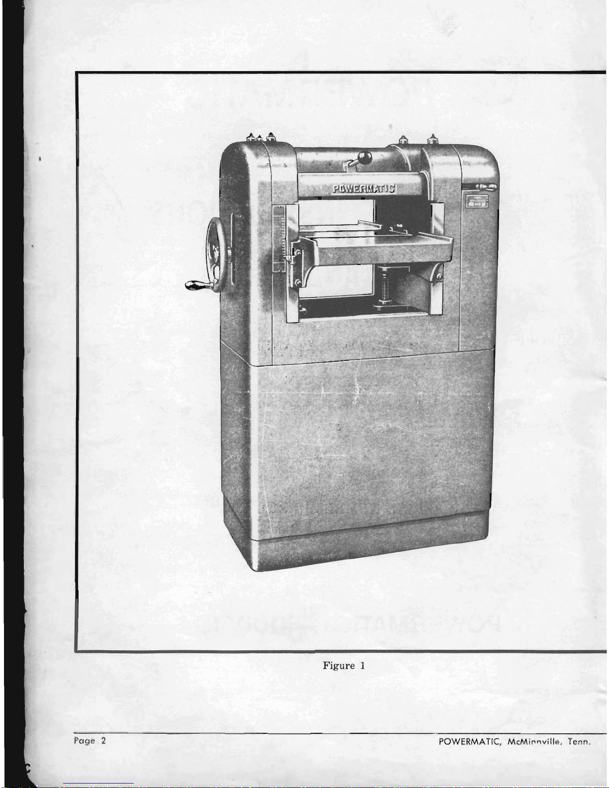
Figure 1
Page 2
POWERMATIC,
McMil'nville, Tenn
.
Page 3
Model
100·12"
Planer
OPERATING INSTRUCTIONS
1.
FRAME
2.
BED
3.
CUTTERHEAD
4.
CHIP BREAKER
5.
FEED ROLLERS
6.
RATE
OF
SPEED
7.
POWER FEED
CONTROL
8.
GUARDS
9.
CAPACITY
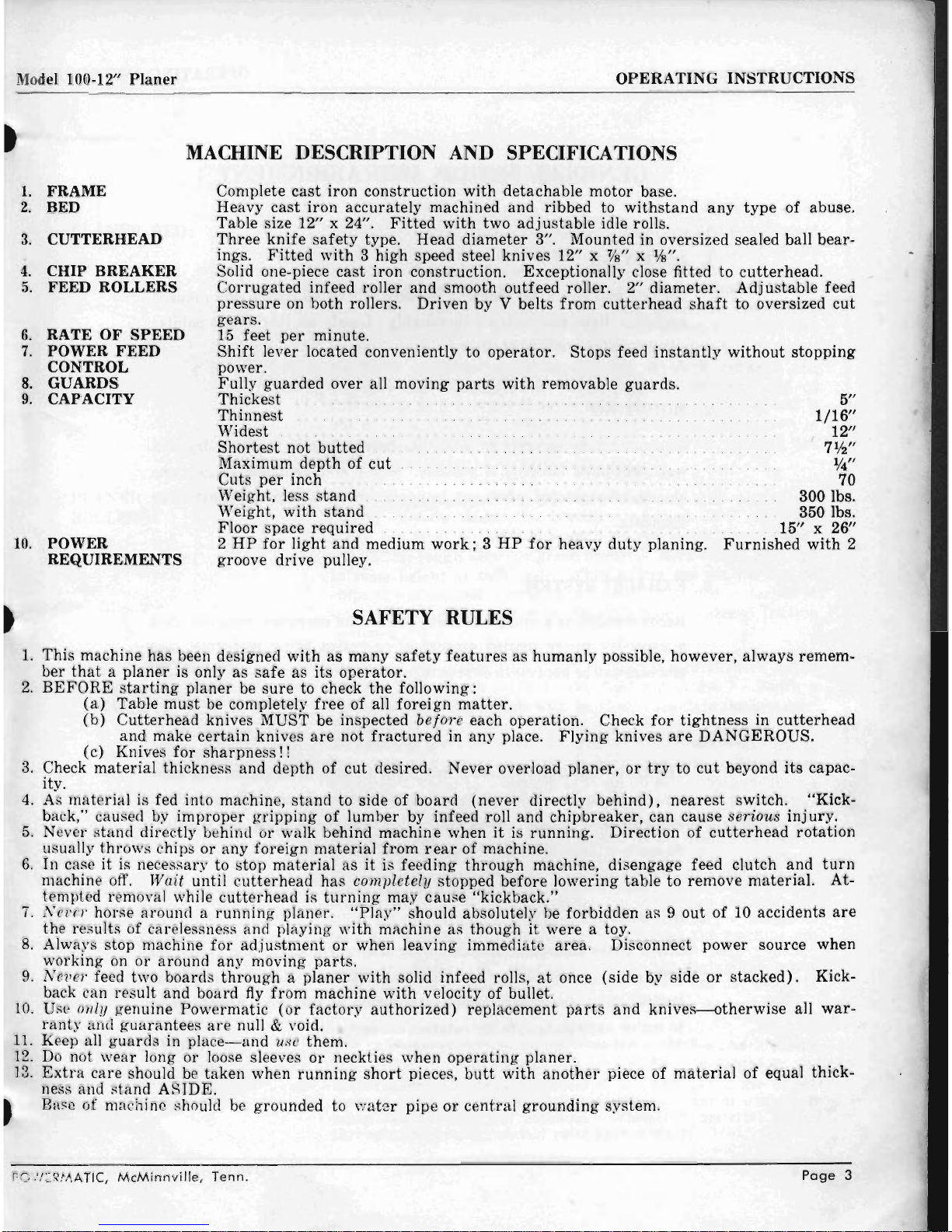
MACHINE DESCRIPTION
AND
SPECIFICATIONS
Complete
cast
iron construction
with
detachable motor base.
Heavy cast iron accurately machined
and
ribbed to
withstand
any
type
of abuse .
Table size 12" x 24".
Fitted
with
two
adjustable
idle rolls.
Three
knife
safety
type. Head diameter 3". Mounted in oversized sealed ball
bear-
ings.
Fitted
with
3 high speed steel knives 12" x %" x
Ifs".
Solid one· piece
cast
iron construction. Exceptionally close fitted to
cutterhead.
Corrugated
infeed roller
and
smooth outfeed roller. 2" diameter.
Adjustable
feed
pressure
on both rollers. Driven by V belts
from
cutterhead
shaft
to oversized
cut
gears.
15
feet
per
minute.
Shift
lever located conveniently to
operator.
Stops feed
instantly
without
stopping
power.
Fully
guarded
over all moving
parts
with
removable guards.
Thickest
...........
. .
Thinnest
......
. .
Widest
.......
.
Shortest
not butted
Maximum
depth
of
cut
Cuts
per
inch
Weight, less
stand
Weight,
with
stand
Floor space required
.....
10.
POWER
REQUIREMENTS
2
HP
for
light and medium
work; 3 HP
for
heavy
duty
planing.
groove drive pulley.
5"
1/16"
12"
7'h"
%"
70
3001bs.
3501bs.
.
.. ..15" x 26"
Furnished
with
2
SAFETY RULES
1.
This machine has been designed
with
as
many
safety
features
as humanly possible, however, always remem·
ber
that a planer
is only as
safe
as
its
operator.
2.
BEFORE
starting
planer be
sure
to check
the
following:
(a)
Table
must
be completely
free
of all
foreign
matter.
(b)
Cutterhead
knives MUST be inspected
before
each operation. Check
for
tightness
in
cutterhead
and
make
certain
knives
are
not
fractured
in
any
place.
Flying
knives
are
DANGEROUS.
(c) Knives
for
sharpness!!
3.
Check
material
thickness
and
depth of
cut
desired. Never overload planer,
or
try
to
cut
beyond its capac-
ity.
4.
As
material
is fed into machine,
stand
to side of
board
(never
directly
behind),
nearest
switch. "Kick-
back," caused by
improper
gripping
of lumber by infeed roll and chipbreaker, can cause serious
injury.
5.
Never
stand
directly behind or walk behind machine when
it
is
running.
Direction of
cutterhead
rotation
usually
throws
chips
or
any
foreign
material
from
rear
of machine.
6.
In case
it
is necessary to stop
material
as
it
is feeding
through
machine, disengage feed clutch and
turn
machine off.
Wait
until
cutterhead
has
completely stopped before lowering table to remove
material.
At·
tempted removal while
cutter
head is
turning
may
cause
"kickback."
7.
Nev
er horse around a
running
planer.
"Play"
should absolutely be forbidden as 9
out
of 10 accidents
are
the results of carelessness and playing
with
machine as though
it
were
a toy.
8.
Always stop machine
for
adjustment
or when leaving immediate
area
. Disconnect power source when
working on or around
any
moving
parts.
9.
Never
feed two boards
through a planer
with
solid in feed rolls,
at
once (side by side
or
stacked).
Kick-
back can result
and
board
fly
from
machine
with
velocity of bullet.
10.
Use only genuine Powermatic
(or
factory
authorized) replacement
parts
and
knives-otherwise
all
war·
ranty
and
guarantees
are
null & void.
11.
Keep all
guards
in
place-and
use them.
12.
Do
not
wear
long
or
loose sleeves
or
neckties when
operating
planer.
13.
Extra
care should be taken when
running
short
pieces,
butt
with
another
piece of
material
of equal
thick·
ness and Rtand
ASIDE.
t Base of machine
Rho
uld be grounded to
water
pipe
or
central
grounding
system.
rO:I::~MATIC
,
McMinnville,
Tenn
.
Page
3
Page 4
Model 100-12"
Planer
OPERATING
INSTRUCTION~
Page
4
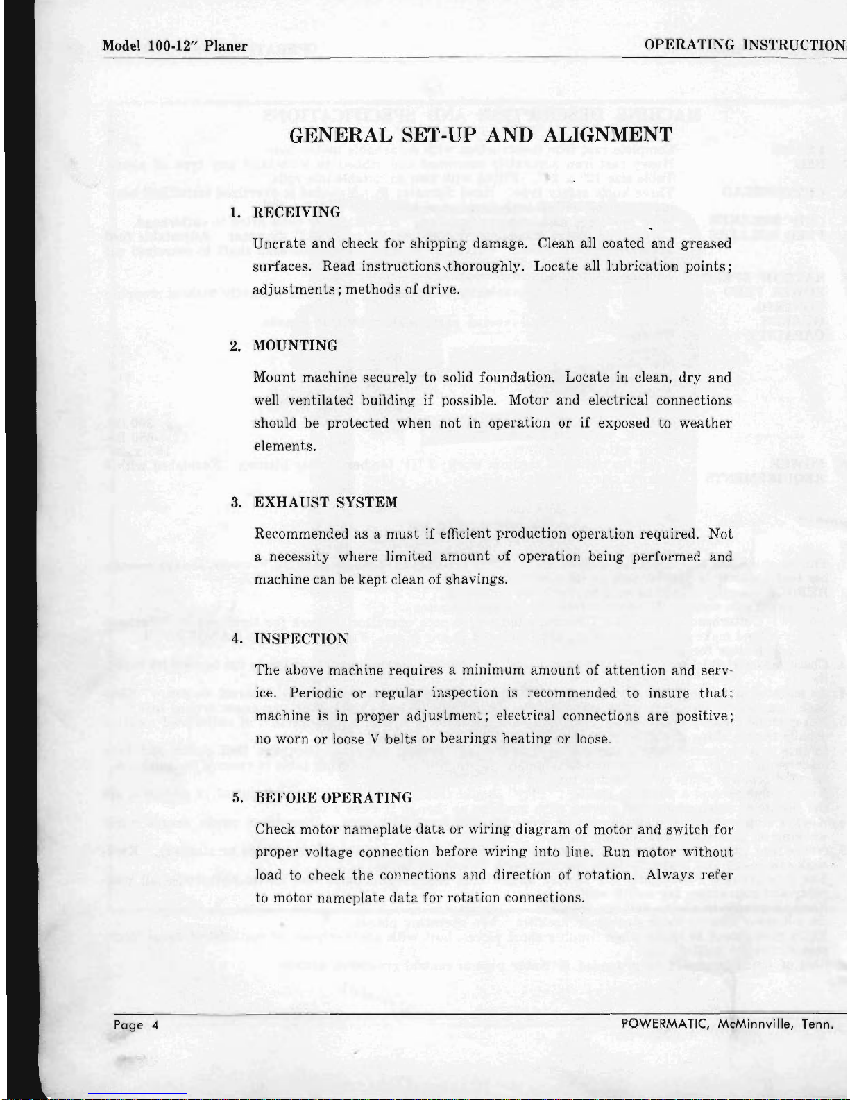
GENERAL SET-UP AND ALIGNMENT
1.
RECEIVING
Uncrate
and check
for
shipping damage. Clean all coated and
greased
surfaces. Read
instructions
,thoroughly. Locate all lubrication
points;
adjustments;
methods of drive.
2. MOUNTING
Mount machine securely to solid foundation. Locate in clean,
dry
and
well ventilated building
if
possible. Motor and electrical connections
should be
protected
when
not
in operation
or
if
exposed to
weather
elements.
3.
EXHAUST
SYSTEM
Recommended
as a must
if efficient production operation required. Not
a necessity
where
limited
amount
vf operation beiug performed and
machine can be
kept
clean of shavings.
4.
INSPECTION
The above machine requires a minimum
amount
of
attention
and serv-
ice. Periodic
or
regular
inspection is recommended
to
insure
that:
machine is in
proper
adjustment;
electrical connections
are
positive;
no
worn
or
loose V belts or bearings
heating
or
loose.
5.
BEFORE
OPERATING
Check
motor
nameplate
data
or
wiring
diagram
of
motor
and
switch
for
proper voltage connection before wiring into line. Run motor without
load to check
the
connections and direction of rotation. Always
refer
to motor nameplate
data
for
rotation
connections.
POWERMATIC,
McMinnville, Tenn.
Page 5
Model 100·12"
Planer
PLANER BED:
PLANER BED IDLER
ROLLERS:
POWER DRIVE
FEED
ROLLS:
CHIPBREAKER:
POWERMATlC,
McMinnville,
Tenn.
OPERATING INSTRUCTIONS
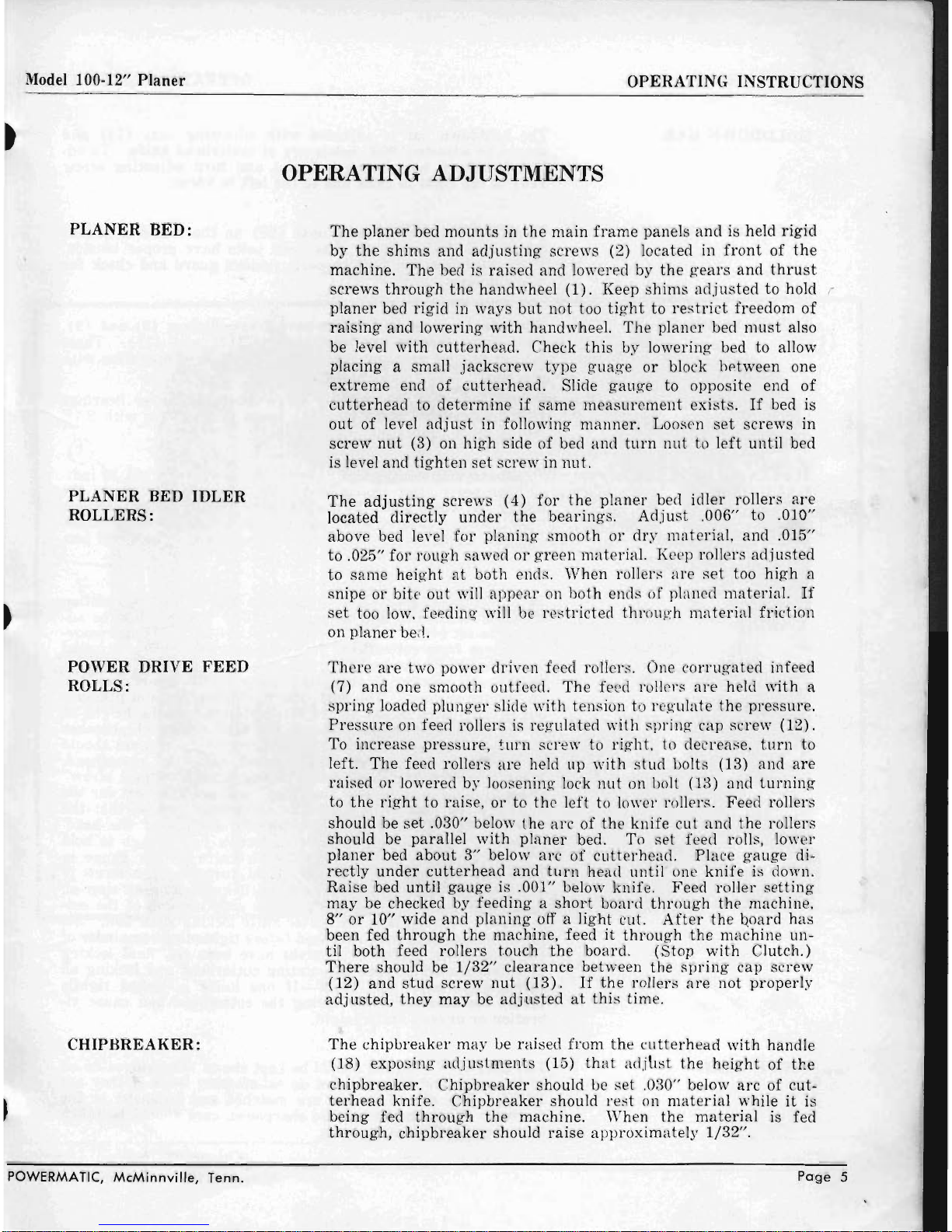
OPERATING ADJUSTMENTS
The
planer
bed
mounts
in
the
main
frame
panels
and
is held
rigid
by
the
shims
and
adjusting
screws (2) located in
front
of
the
machine.
The
bed is
raised
and
lowered
by
the gears
and
thrust
screws
through
the
handwheel
(1).
Keep
shims
adjusted
to
hold
I'
planer
bed rigid
in
ways
but
not
too
tight
to res
trict
freedom
of
raising
and lowering
with
handwheel.
The
planer
bed
must
also
be level
with
cutterhead.
Check
this
by lowering bed to allow
placing a small
jackscrew
type
guage
or
block hptween one
extreme
end
of
cutterhead.
Slide
gauge
to opposite end
of
cutterhead
to
determine
if
same
measurement
exists.
If
bed is
out
of level
adjust
in following
manner.
Loosen
set
screws in
screw
nut
(3) on
high
side
of
bed and
turn
nut
to
left
until
bed
is level and
tighten
set screw
in
nut.
The
adjusting
screws
(4)
for
the
planer
bed
idler
rollers
are
located
directly
under
the
bearings.
Adjust
.006" to .010"
above bed level
for
planing smooth
or
dry
mat
erial, and .015"
to .025"
for
rough
sawed
or
green
mat
erial. Keep rollers
adjusted
to
same
height
at
both
ends.
When
rollers
are
set
too
high
a
snipe
or
bitE'
out
will
appear
on
both
ends of planed
material.
If
set
too low. feedin
l?,
' will be
restricted
thr
ough
material
friction
on
planer
be,t
There
are
two power
driv
en feed rollers. One
corrugated
infeed
(7) and one smooth outfeed.
The
fe ed rollers
are
held
with
a
spring
loaded plung
er
slide
with
tension to regulate
the
pressure.
Pressure
on feerl rollers is
regulated
with spring
cap screw (12).
To increase
pressure, turn
screw to
right,
to decrease,
turn
to
left.
The
feed rollers
are
held up
with
stud
bolts
(3)
and
are
raised
or
lowered by loosening lock
nut
on bolt (13) and
turning
to
the
right
to raise,
or
to
the
left
to lower rollers.
Feed
rollers
should be
set
.030" below
the
arc
of
the
knife
cut
and
the
rollers
should be parallel
with
planer
bed. To
set
feed rolls, lower
planer
bed
about
3"
below
arc
of
cutterhead.
Place
gauge
di-
rectly
under
cutterhead
and
turn
head until one
knife
is down.
Raise
bed
until
gauge
is .001" below knife.
Feed
roller
setting
may
be checked by feeding a
short
board
through
the
machine,
8"
or
10" wide
and
planing
off a
light
cut.
After
the
Qoard
has
been fed
through
the
machine, feed
it
through
the
machine un-
til both feed rollers touch
the
board.
(Stop
with
Clutch.)
There
should be
1/32"
clearance between
the
spring
cap
screw
(12)
and
stud
screw
nut
(13).
If
the
rollers
are
not
properly
adjusted,
they
may
be
adjusted
at
this
time.
The
chipureaker
may ue raised
from
the
cutterhead
with
handle
(18) exposin g
adjustments
(15)
that
adjLst
the
height
of
the
chipbreaker.
Chipbreaker
should be s
et
.030" below
arc
of
cut-
terhead
knife.
Chipbreaker
should rest on
material
while
it
is
being fed
through
the
machine. When
the
material
is fed
through,
chipbreaker
should
raise
approximately
1/32".
Page
5
Page 6

Model 100-12"
Planer
HOLDDOWN
BAR:
FEED
DRIVE
BELTS:
MATERIAL
THICKNESS
GAUGE:
CUTTERHEAD:
KNIFE
CARE:
Page
6
OPERATING INSTRUCTIONS
The holddown
bar
is
adjusted
with
adjusting
nuts
(14) and
should be
adjusted
.003" below
arc
of
cutter
head knife. To ad-
just
hold down
bar,
loosen lock
nut
and
turn
adjusting
screw
(14) to
the
right
to
raise
and
to the
left
to lower .
To
adjust
feed belts, loosen
nuts
(20)
on the inside of
planer
frame
and
slide
studs
in slots until belts have
proper
tension.
If
machine does not feed properly remove
guard
and check for
belt slippage.
The infeed
and
outfeed rollers have
grea
se fittings (8) and
(9).
Feed drive sheaves
are
lubricated
at
(16) and
(17).
These
fittings
require
greasing
every ten (10) hours of operation with
No.1
grease,
or
a light weight type.
Planer
bed ways, bed
raising
screws, bed idle roller bearings
should be greased every ten
(10)
hours
of operation
with
SAE
No. 10 oil
or
equivalent.
To set
the
indicator on the
material
thickness scale (6) to indi-
cate
properly
after
changing knives, loosen
the
screw in the
planer
bed which holds
the
brass
pointer
and set to
the
thickness
the
material
measures when planed or fed
through
the
machine.
The hole which mounts the
brass
pointer
is slotted
and
will per-
mit
proper
adjustment.
The
cutter
head is equipped
with
three
knives held in position
with
the
lock shims
and
set screws
(10).
Knives
must
be ad-
justed
to
set
evenly and level in the
cutterhead.
Before remov-
ing knives from cutterhead,
the
knife
gauge
should be adjusted
to
the
height
of
the
knives. so
the
height
of
the
knives will not
be changed relative to the
other
parts
of
the
head when the
knives
are
replaced . The feed rollers,
chipbreaker
and pressure
bar
are
adjusted
to the
arc
of
the
knife
cut.
If
the height of
the
knives
are
raised
or
lowered, the feed rollers, chipbreaker
and
pressure
bar
should be
adjusted
accordingly. Knives should
not
protrude
more
than
.030" beyond
radius
of cutterhead.
When replacing knives
after
sharpening,
place
the
"jack
screw"
studs
in place
making
sure
the
"step"
will
act
as a seat
for
the
knife. Drop knife
and
shim into
cutterhead
slot so
that
the
beveled edge of knife is
just
below
the
surface
of the head.
Tighten
the two outside knife shim screws
just
enough to hold
the
knives snugly in the head., With knife
settin~
gauge in
place over one
extreme
end of
the
head,
turn
the
allen screw in
"jack
screw"
plugs,
raising
knife until knife touches stop on
knife
setting
gauge. Repeat operation on
other
end of
the
cut-
terhead.
Next,
tighten
the
center
knife
locking shim bolt. Set
the
other
knives in
the
cutterhead
before
tightening
remainder
of
the shim bolts.
After
th~
knives have been set, final locking
of knives should be done by
rotating
cutter
head and locking all
shims uniformly.
CAUTION-If
one knife is locked tightly
before
the
others,
it
may
spring
the
cutterhead
and cause vi-
bration
or
uneven knife height.
IMPORTANT:
Knives should be kept
sharp.
The knive s
do
all
of
the
work
and
they
will
not
do
satisfactory
work
if
they
are
DULL. The sets of knives
are
matched and balanced
at
the
factory. When
the
knives
are
sharpened, care should be taken
that
they
are
kept
in balance.
POWERMATIC,
McMinnville,
Tenn.
Page 7

Figure
1
POWERMATIC,
McMinnville,
Tenn.
Page
7
Page 8

Page 8
60067-2
100-17
100 -32
====r-:==t===:::::;2d~
7fi7i,.~
~~
100-30
---
100-08
----'-----I--_
f-...
60035-6
-----.;---
60002-1
----l---
I
---2::
100-16
-11---1-----
60002-3
------
I-
---~
60025-4
------'-----.L-:---~
100.05
-----------1----
-.,
----.
100-102=----------f--
~'·
----.
100-66
----------+--~~--=:
100-55
===========!=====~
100-54
60014-1
---------------=
40136-2
100-54
----------------
100-26
---------------....::
60025-2
---------------
60014-1
60078-7
---------------
100-25
--------------~
100-18
--------------~
40092
100-24
-==============
40111-3
-
40092
100 -73
--------------.
60014-1
100-29
---------
60078-5
---------
100~2
---------.
100 -62
--------
100-
29
-------
100-23
------
60067
-3
-----=:---
60003-1
---
60026-5---
100-12
---
100-20
-----"'
.~
100-21
----.-.:
60014-2
----~~
60002-1
-----
100-18
======
________________
---.J
100-48 =====-------------=====:::..
100-47 1
------
100-35A -
60002-3
-
60002-3
-
100-39
100-80
100-37
POWERMATIC, McMinnville, Tenn.
Page 9

I
~
=
===============60067-2
00-(8
=
==-----==
60002-3
=
---------== 60002-3
00-36
:::.:
~~~-=--=--=--=--=--=-========
60014-5
00-35
::-~~~~~~~~~~~~~~~=
IOO-JJ
=
==-----====
00·00
00-06
::==--';11;======60014
-1
~~':111/'---
,18020-1
N
60014-1
---~----------==-
- 00-11
~
00-42
~
~-----===
00-102
~
~~
~=--=======-
00-13
~
:::::=----=====
40112-8
00-43
====--------00-01
00-06
~-----=======-60120
.
-------==
60005-4
'-
00-57
~
=-----~=========-==========-==-=~~~~~~~~~===60003-1
~
~======================
60002-3
00-100
~
-U~~~~~~~~60002-1
L.rL=
00-77
00-107
/J
POWERMATlC,
McMinnville, Tenn.
Page 9
Page 10

Figure
2
Page
10
POWERMATIC,
McMinnville,
Tenn.
Page 11

®
Figur
e 3
POWERMATlC,
McMinnville,
Tenn.
Page
11
Page 12

PLANER OPERATING HINTS
IF CLIP OR
SNIPE
APPEARS
AT BEGINNING
OF
BOARD
1.
Pressure
bar
may
be
set
too low.
2.
Chipbreaker
may be
set
too high.
3.
Upper
infeed sectional roll
may
be
set
too
high
.
4.
Lower
infeed roll
may
be
set
too high.
5.
Spring
tension
may
be too
light
on
pressure
bar.
6.
Bed
may
be too loose.
IF
CLIP
OR
SNIPE
APPEARS
ON
END
OF LUMBER:
1.
Pressure
bar
may
be
set
too high.
2.
Lower outfeed roll
may
be
set
too high.
3. '
Upper
outfeed roll
may
be
set
too low.
4.
Lumber
may
not
be butted.
5.
Grai.n
may
be
running
against
knives.
IF
KNIVES
TEAR
OUT
LUMBER:
1.
Feed
may
be too
fast.
2.
Moisture
content
may
be too high.
3. Head
may
be
running
too slowly.
4.
Cut
may
be too heavy.
5.
Cutting
angle
may
be too large.
6.
Grain
may
be
running
against
knives.
IF
KNIVES
RAISE
THE
GRAIN:
1. Feed
may
be too
fast.
2.
Cutting
angle
may
be too large.
3.
Head
may
be
running
too slowly.
4.
Moisture
content
of lumber
may
be too high.
5.
Cut
may
be too heavy.
IF CHIP MARKS
APPEAR
ON
LUMBER:
1. Blower
system
may
not
be
strong
enough.
2.
Feed
may
be too
fast.
3. May be loose connection in blower
system-no
suction.
4.
Exhaust
pipe
may
join
at
too
large
an
angle to main blower pipe.
IF
PANELS
ARE
TAPERED
ACROSS
THE
WIDTH:
1.
Planer
bed
out
of level
with
cutterhead.
2.
Knives
not
set
even
with
cutterhead.
IF
UNDESIRED
POUNDED GLOSSY
FINISH
APPEARS:
1.
Knives
may
be dull.
2.
Feed
may
be too slow.
Page
12
POWERMATIC,
McMinnville,
Tenn.
Page 13

Model 100-12"
Planer
OPERATING INSTRUCTIONS
IF
WASHBOARD
FINISH
APPEARS:
1. Knives
may
have
been
driven
back
into
the
head.
2.
Machine
may
be completely
out
of
adjustment.
3.
Planer
bed loose
and
rocking
in
ways.
IF
REVOLUTION MARKS SHOW
UP:
1. Knives
may
be
ground
poorly.
2.
Knives
not
set
properly
or
evenly.
IF
LINES
APPEAR
AT RIGHT ANGLES
TO
THE
KNIFE
MARKS:
1. Knives
may
have checkered
and
nicked up
by
overgrinding
and
taking
temper
out
of
steel.
2.
Chips
may
have
wedged
between
rolls
and
tables.
3.
Pressure
bar
may
be
dragging.
IF
STOCK TWISTS IN MACHINE:
1.
Pressure
bar
may
be cocked.
2.
Upper
outfeed
roll
may
be cocked.
3.
Upper
outfeed
roll
may
have
uneven
spring
tension
on
it.
4.
Lower rolls
may
be cocked.
IF
STOCK STICKS OR HESITATES IN MACHINE:
1.
Pressure
bar
may
be
set
too low.
2.
Lower rolls
may
be
set
too low.
3.
Upper
rolls
may
not
be
set
low enough.
4.
Cut
may
be too heavy.
5. Coaxer
board
may
help
lumber
through
machine.
6.
Feed
belts
may
be slipping.
IF
MACHINE IS NOISY AND VIBRATES AND POUNDS:
1. Knives
may
be too dull.
2.
Machine
may
not
be leveled
up
correctly.
3. Machine
may
not
be on solid foundation.
4.
Pressure
bar
may
be
set
too low.
IF
MOTORS KICK OUT:
1. Knives
may
be dull,
thus
overloading
motors.
2.
Pressure
bar
may
be'
set
too low,
putting
drag
on
motors.
3.
Motors
may
be
drawing
high
current
because
other
machinery
in
the
plant
in use
has
pulled down
the
voltage.
4.
Machine
may
be
out
of
adjustment.
5. Lower rolls
may
be
set
too low.
POWERMATIC,
McMinnville,
Tenn.
Page
13
Page 14

Model 100-12"
Planer
OPERATING INSTRUCTIONS
Part
No.
100-1
100-2
100-3
100-4
100-5
100
-6
100-8
100-9
100-10
100-11
100-12
100-13
100-16
100-17
100-18
100-20
100-21
100-22
100-23
100-24
100-25
100-26
100-29
100-30
100-32
100-33
100-35
100-35A
100-36
100-37
100-39
100-42
100-43
100-44
100-46
100-47
100-48
100-50
100-51
100-52
100-53
100-54
100-55
100-57
100-58
100-59
100-60
100-62
100-66
PARTS LIST FOR MODEL
100-12"
PLANER
STATE PLANER SERIAL
NUMBERS
\VH
EN
ORDERING
PARTS
Description
Cutterhead
Roller,
Outfeed
Roller,
Infeed
Chipbreaker
Bearing
Housing,
R
Bearing
Housing
, l
Table
Belt
Guard
Stud,
Cutterhead
Guard
Pulley, 2
AK
27
Pin
____________
_
Bearing,
Fafnir,
206Kll
_________
_
Shim,
Table
Adj
Feed
Drive
Guard
Assy
Stud
Feed
Drive
Guard
Mtg
_
lever,
Clutch
Brkt, Clutch
lever
Mtg
Sheave,
Clutch
Collar
& Clutch
Pinion, Clutch
lever
____________
_
Shaft,
Clutch Pinion _
__
______
__
Brkt, Clutch Mtg
_________________
_
Gear,
Feed
Roller Drive
Bearing
Housing
Table
Roller
Stud,
Feed
Roller
Bearing
_
Spring, Outfeed
Press
Stud, 12102
__
Spring,
Infeed
Press
Stud, 12101
Nut,
Feed
Roll
Spring
_____________
_
Stud,
Pressure
Bar
Bushing
Pressure
Bar
Shaft
__ _ ________________
_
Gear
____________________
_
Gear
____ . _________
_
Bearing
, Thrust, Nice
605
__ . __
_
Screw
(lH)
_____ _____ _ ________
_ _
_____
_
Nut
____
_
*Belt, Clutch ,
Browning
33A
__
_
*Belt,
Cutterhead, Browning
36A
_
*Belt,
Compound
Drive,
Brwng
28A
Hange~
Compound
Sheave
Sheave
,
Compound
Shaft, Threaded
Pressure
Bar
Shim, Cutte
rhead Knife
Jacksc
rew
Peanut
Brace
Front
Pane
l
Spacer
, Clutch
Space
r,
Comp
Feed
Roller
No
.
Required
1
1
1
2
2
2
1
2
2
2
2
1
2
2
1
2
2
4
2
2
2
2
3
Part
No.
100-72
100-73
100-77
100-83
100-86
100-89
100-92
100-102
100-106
100-107
100-108
18020-1
40092
40111-3
40111 -7
40112-8
40136-2
60002-1
60002
-3
60002-6
60003-1
60005-4
60008-3
60014-1
60014-2
60014-5
60025-2
60025-4
60025
-1
(\
60026-1
60026
-5
60026-6
60026-7
60035
-3
60035-6
60062
60067-2
60067
-3
6
0078-
5
60078-7
60120
60025
-4
100-80
1200-623
Description
Shaft
Compound
Sheave
Grease,
Alemite,
Va
Pipe
Stand
Assembly
Main
Frame
___
_
Cutterhead
Knife
Knob
Handwheel
Bearing
Housing
_____________ _ __ _ ______
_
Slotted
Head
SS,
5/16
- 18 x 1
Screw
__
Nut
Handwheel
Collar
Key, 3/
16 x 3/16
x
Key, 3/ 16 x
3/16
x 1Y2
Key,
\~
x
\4
x 1 %
Pulley, AS-
26
Nut
, Hex, 5 / 16 - 18
Nut, Hex,
% -
16
____
_
Nut, Hex, Y2 - 13
____________________
_
lock
Washer,
5/16
_____________
_
Socket
Cap
Screw,
5/16
- 18 x Y2 _
Split Pin,
\4
x 1
\4
Socket
Set
Screw,
5/16
- 18 x %
___
_
Socket
Set
Screw,
5/16
- 18 x
Yl
Socket Set
Screw,
5/ 16 - 18 x 1
Hex
Head
Cap
Screw,
3/
S
- 16 x 1
Hex
Heod
Cap
Screw,
% - 16 x ]34
l:Iex
Head
Cap
Screw,
% - 16 x 1
\4
Washer
Flat, %
Washer
Flat, 5/
16
Washer
Flat, Y2
___________________________
_
Washer
Flat, %
____________
_
Square
Head
Set
Screw, 5/16-
18 x
Yl
_____
_
Square
Head,
Set
Screw,
5/16
-
18
x 1 Y2
__
____
__
Rivet ,
\4
x 3
Hex
Head
Cap
Screw,
5/16-
18x
Yl
Hex
Head
Cap
Screw,
5n 6 18 x
11
1"
Bushi
ng,
Oi lite
Bushing, Oilite
Grease,
Alemi
te
_____________
______ _
Hex
Head
Cap
Screw
, % -
16
x 134
Spring
Handle
'No
t Picture d
No.
Required
1
3
2
2
1
2
1
6
10
1
2
~
4
14
2
4
2
4
1
5
18
4
4
2
4
4
4
2
-P-a-g-e--14--------------------------
--
---
-----
---------------------P~O~\-
V~[~R
~M~,A~T~.;~(-,~i.~A
~~-:-~~~in-n-v~ii~:e-,~ienn.
Page 15

Page 16

 Loading...