

Porsche M 44/01, M 44/02, M 44/05, M 44/04, M 44/06 Workshop Manual
...
Workshop Manuel
Volume I - Engine, 8 valves
DR. ING. h. c. F. PORSCHE Aktiengesellschaft
WORKSHOP MANUAL 944
This Workshop Manual descr
ibes all of the important operations for which special instructions are required to
assure proper completion. This manual is essential for shop foremen and mechanics, who need this
information to keep the vehicles in safe operating condition. The basic safety rules, of course, also apply to
repairs on vehicles without exception.
Only those repair jobs deviating from those of vehicle type 924 are described in the 944 Workshop Manual.
Refer to the 924 Workshop Manual for all other information.
The information is grouped according to repair numbers which are identical to the first two digits of the
warranty job codes.
The repair group index, list of contents and the register tabte are quick guides to find information in the
manual. The layout drawings in this manual are numbered in the order of disassembling and, if necessary,
also have information on assembly or installation and application of special tools.
Descriptions of design and function can be found in the service training course reference material.
This Workshop Manual will be kept up to date with Technical Information Bulletins, which will be made part
of the manual from time to time. We recommend that these bulletins be filed in the standard type folder
provided for this purpose.
Printed in Germany

List of Repair Groups 944
General
Technical Data Page 0.1
Repair Groups
Group
Maintenance, Self-diagnosis 03
Engine
Engine, Crankcase
Engine, Crankshaft, Pistons
Engine, Cylinder Head and Valve Drive
Engine, Lubrication
Engine, Cooling
Fuel Supply
Air Flow Controlled Fuel Injection
Exhaust System/Emission Controls
Starter, Power Supply, Cruise Control
Ignition System
DME Diagnosis
10
13 15 17 19 20
24
26 27
28
Transmission
Clutch, Controls
Torque Converter
Manual Transmission, Controis, Case
Manual Transmission, Gears, Shafts
Autornatic Transmission, Controls, Case
Automatic Transmission, Gears, Valve Body
Differential, Transaxle System
30
32 34 35 37 38
39
Chassis
Front Wheel Suspension
Rear Wheel Suspension, Axle Shaft
Wheels, Tires, Alignment
Antiblock System
Brakes, Mechanical
Brakes, Hydraulics, Regulator, Booster
Steering
40
42
44
45 46 47
48
Body
Body-Front Section
Body-Center Section
Body-Rear Section
Lids
Doors
Hardtop
Bumpers
Glasses, Window Control
Exterior Equipment
Interiør Equipment
Seats
Seat Covers
Airbag Diagnosis
50
51 53 55 57 61 63 64 66 68 72
74
Heating,
Ventilation,
Air Condition
Heater
Ventilation
Air Conditioner
80
85
87
Electrics
Instruments, Fuel Gauge, Alarm System
Radio, Telephone
Windshield Wipers and Washer
Exterior Lights, Lamps, Switches
Interiør Lights
Wiring
90
91 92
94
96
97
Printed in Germany - XXI, 1989

9 4 4
0 Blank Page

944 Table of contents volume I
General
Technical data
Engine, Crankcase
Tolerances and wear limits
Tightening torques for engine
Engine, removing and installing (manual transmission)
Hydraulic engine mounts, removing and installing
Checking hydraulic engine mounts
Installing new hydraulic engine mounts
Engine, Crankcase, Pistons
Checking and adjusting tension of Poly-rib belt for
alternator and compressor
Checking adjustment of compensating shaft
Checking and adjusting tension of the power pump belt
Calibrating Special Tool 9201
Checking and adjusting toothed belt tension - compensating shafts
Checking and adjusting toothed bert tension - compensating shafts (idler pulley with
slot)
Installing toothed belt - compensating shaft
Application - assembly stand VW 540 and engine holders 9127 and 9197
Identification of engine number on crankcase
Identification code, crankcase engine number
Crankcase and crankshaft, disassembling and assembling
Installing cover for the centrifugal compartment
Checking crankshaft bearing play
Identification code - upper and lower crankcase sections and compensating shaft
cover
Sealing crankcase - upper and lower sections
Installing upper and lower crankcase sections
Aligning upper and lower crankcase sections
Installing crankshaft seal (flywheel side)
Flywheel and grooved ball bearing, removing and installing
Refacing the flywheel
Replacing setscrew (reference mark sensor)
Setting crankshaft to TDC, cylinder 1
Crankshaft dimensions - standard and machined
Checking pistons and cylinder bore
Pistons, disassembling and assembling con rods
Installing pistons with con rods
Pistons, from Model 89 onwards
Installing pistons with con rods
Holding the flywheel for assembly work (with engine installed)
Page
0.2
10 - 01
10 - 03
10 - 1
10 - 7
10 - 10
10 - 11
13 - 1
13 - 2
13 - 2a
13 - 2b
13 - 3
13 - 6
13 - 11
13 - 13
13 - 14
13 - 14b
13 - 15
13 - 20 b
13 - 21
13 - 22
13 - 23
13 - 24
13 - 24 a
13 - 25
13 - 26
13 - 26a
13 - 27
13 - 28
13 - 29
13 - 31
13 - 32
13 - 34 a
13 - 34 b
13 - 35
13 - 37
Table of contents
Printed in Germany - XXIV, 1993
1

volume I Table of contents 944
Compensating shaft drive, disassembling and assembling
Installing bearing bridges for compensating shafts
Compensating shaft drive, disassembling and assembling
Compensating shaft drive sprockets, installing (Model 84 onwards)
Machining cylinder bores
Engine, Cylinder head, Valve drive
Camshaft belt tension, checking and adjusting
Installing camshaft belt and adjusting timing
Cylinder head, removing and installing
Tightening specifications for cylinder head
Valve drive, disassembling and assembling
Machining mating face, cylinder head
Replacing valve guides
Valve drive, disassembling and assembling
Machining valve seats, checking valve guides
Valve drive, disassembling and assembling (camshaft housing)
Camshaft drive, disassembling and assembling
Camshaft specifications
Adjusting camshaft belt with mechanical belt tensioner
Engine - Lubrication
Replacing engine oil and oil filter
Parts of the lubrication system, removing and installing
Oil pump, disassembling and assembling
Sleeve for oil-pressure relief valve, removing and installing
Tightening specifications for oil-pump fastening screws.
Checking oil pressure
Oil check valve in cylinder head, removing and installing
Cleaning the engine oil system
Cleaning the main oil channel in the crankcase
Pressure-reducing valve, removing and installing
Engine - Cooling
Replacing coolant and bleeding cooling system
Checking thermostat, checking system for leaks
Parts of the cooling system, removing and installing
Parts of the cooling system, removing and installing, Mod. 87 onwards
Radiator, removing and installing
Temperature switch, removing and installing - checking temperature switch
Cleaning cooling system after oil and water have been mixed
Page
13 - 39
13 - 44 f
13 - 44 h
13 - 50
13 - 53
15 - 1
15 - 5
15 - 7
15 - 10 a
15 - 11
15 - 16 a
15 - 16 b
15 - 17
15 - 19
15 - 20
15 - 25
15 - 28
15 - 29
17 - 1
17 - 3
17 - 10
17 - 12
17 - 13
17 - 14
17 - 16
17 - 17
17 - 18
17 - 19
19 - 1
19 - 3
19 - 4
19 - 6 a
19 - 7
19 - 9
19 - 11
2 Table of contents
Printed in Germany - XXIV, 1993

944 Table of contents volume I
Temperature switch, removing and installing - checking temperature switch
Cleaning cooling system after oil and water have been mixed
Fuel supply
Replacing fuel filter, checking injection lines for leaks and tightness
Checking delivery rate of fuel pump
Fuel pump, removing and installing
Fuel tank, removing and installing
Line routing, fuel system
Active-carbon tank for pollution-free fuel-tank bleeding (layout)
Fuel expansion tank, removing and installing
Checking fuel expansion tank
Fuel-Ievel sensor, removing and installing
L-Jetronic fuel injection
Replacing air-filter cartridge
Testing and adjusting specifications
Testing and adjusting specifications for Model 85/2 onward and 924 S
Checking fuel pressure
Adjusting idle speed
Adjusting idle speed - USA vehicles
Correcting CO setting at air-flow sensor - USA vehicles
Injection valves, removing and installing
Checking intake system for leaks - troubleshooting
Adjusting idle speed for Model 85/2 onward and 924 S
Adjusting idle speed - USA and vehicles with catalytic convertor
from Model 85/2 onward and 924 S
Testing and adjusting specifications, Model 89 onward
Adjusting idle speed and CO for Model 89 onward
Equipment table for Model 89 onward
Exhaust system
Checking exhaust flanges for tightness
Replacing exhaust pipe or primary muffler/catalytic convertor
Starter, Power supply, Tempostat
Automatic cruise control (Tempostat)
Tempostat control unit, removing and installing
Tempostat operating switch (steering-column switch), removing and installing
Actuator, removing and installing
Tempostat bowden cable, removing and installing
Page
19 - 9
19 - 11
20 - 1
20 - 2
20 - 3
20 - 4
20 - 7
20 - 8
20 - 9
20 - 10
20 - 11
24 - 1
24 - 3
24 - 4
24 - 5
24 - 7
24 - 9
24 - 12
24 - 13
24 - 15
24 - 17
24 - 20
24 - 25
24 - 26
24 - 27
26 - 1
26 - 2
27 - 1
27 - 5
27 - 6
27 - 7
27 - 8
Table of contents
Printed in Germany - XXV, 1992
3

volume I Table of contents 944
Tempostat bowden cable, removing and installing
Clutch switch, removing and installing
Troubleshooting-Tempostat
Checking multiple-pin connector of Tempostat control unit
Checking multiple-pin connector of Tempostat actuator
Automatic cruise control (Tempostat) from Model 85/2 onward
Tempostat control unit, removing and installing steering-column switch
from Model 85/2 onward
Actuator, removing and installing, from Model 85/2 onward
Clutch switch, removing and installing, from Model 85/2 onward
Troubleshooting - Tempostat - from Model 85/2 onward
Connector assignment, Tempostat control unit
Checking the multiple-pin connectors of the Tempostat control unit
from Model 85/2 onward
Alternator, removing and installing
Ignition system
Equipment table
Accident hazards in electronic ignition systems
Ignition-distributor cap, removing and installing
Replacing spark plugs
DEE
Speed and reference-mark sensors, removing and installing
Troubleshooting-DEE
Functional test-Lambda probe
Test - DEE control unit, test - Lambda probe
DEE control unit, removing and installing, from Model 85/2 onward
DEE control unit coding - 924 S from Model 86 onward
DEE control unit coding - 944, from Model 85/2 onward
DEE control unit coding - 944, 2.7 l
DEE control unit coding - 944 turbo, from Mod. 85 onward
DEE control unit coding - 924 S, from Model 88 onward
DEE control unit coding - 944, from Model 88 onward
Equipment table engine type M 44.09 to 12
Page
27 - 8
27 - 9
27 - 10
27 - 11
27 - 12
27 - 13
27 - 17
27 - 19
27 - 20
27 - 21
27 - 22
27 - 23
27 - 25
28 - 1
28 - 3
28 - 5
28 - 7
28 - 10
28 - 14
28 - 16
28 - 37
28 - 38
28 - 39
28 - 41
28 - 42
28 - 42 a
28 - 43
28 - 45
28 - 46
28 - 47
4 Table of contents
Printed in Germany - XXV, 1992

944 G e n e r a l
Printed in Germany 0.1

G e n e r a l 944
TECHNICAL DATA
(adjusting values and wear limits appear in pertinent repair groups)
Note: USA values in brackets.
E n g i n e M 44/01 manuals - M 44/03 automatics
(M 44/02 manuals - M 44/04 automatics)
M 44/05 manuals - M 44/06 automatics
(M 44/07 manuals - M 44/08 automatics)
Number of cylinders
Bore
Stroke
Displacement (actual)
Displacement (tiscal)
Compression ratio
Max. engine power
to 80/1269/EC
Net power, SAE J 1349
At engine speed
Max. torque to 80/1269/EC
Net torque, SAE J 1349
At engine speed
Max. specitic power output
Net power to SAE J 1349
Fuel grade
Engine speed limit
Engine weight (dry)
mm/in.
mm/in.
cm3/in.3
cm3
kW/HP
kW/HP
rpm
Nm/kpm
Nm/ft. Ibs.
rpm
kW I / HP I
kW I / HP I
rpm
kg/Ibs.
4
100/3.94
78.9/3.11
2479/151.26
2449
10.6 : 1 (9.5: 1)
120/163 (110/150)
116/156 (105/143)
5800 (5500)
205/20.9 (192/19.6)
199/151.3 (186/137)
3000
48/66 (44.4/60.5)
48/63 (42.4/57.7)
96 RON
(91 RON - unleaded fuel only)
6500
166/366
E n g i n e D e s i g n
Type
Crankcase
Crankshaft
Crankshaft bearings
Water-cooled, axial, 4 cylinder, 4 stroke,
in-line, internat combustion engine with
toothed belt driven overhead camshaft
and two compensating shafts
Two-piece, light alloy
Forged steel
Five
0.2 Technical Data V, 1985 Printed in Germany

944 G e n e r a l
Connecting rods
Conrod bearings
Piston pin bearings
Pistons
Piston pins
Piston rings
Cylinders
Cylinder head
Valve seat inserts (shrink-fit)
Valve guides
Valve arrangement
Exhaust valves
Valve springs
Valve timing
Camshaft
Camshaft bearings
Camshaft drive
Valve clearance
Timing with 1 mm lift
and zero valve clearance
Forged steel/cast since February, 1984
Plain
Press-fit brass bushings
Cast fight alloy
Floating installation, secured with circlips
2 compression rings and 1 oil scraper ring
Light alloy
Light alloy
Intake: FCr 330 Exhaust: CoMo 75
Press-fit special brass
1 intake, 1 exhaust, overhead, in-line
With armored seat
2 coil springs per valve
By overhead camshaft and hydraulic cam
followers
Shell hard east
Camshaft runs in camshaft case without bearing shells
Toothed belt with tensioning roller
Automatie hydraulic adjustment
Intake opens 1° after
Intake closes 49° after
Exhaust opens 43° before
Exhaust closes 3° before
TDC
BDC
BDC
TDC
E n g i n e C o o t i n g Closed cooling system, electric fan with
thermo switch, antifreeze for - 25° C
E n g i n e L u b r i c a t i o n
System
Pressure circulation with siekle-type pump,
oil filter and oil/water heat exchanger in
oil full flow and water bypass integrated in
crankcase
Oil pressure at 5,000 rpm
Oil pressure display
Max. oil temperature
Oil consumption ltr./1000 km
Approx. 4 bar at operating temperature
Indicator lamp and pressure gage
140° C
Up to 1.5
Printed in Germany - V, 1985 Technical Data 0.3

G e n e r a l 944
E x h a u s t S y s t e m Manifold, single pipe up to primary
muffler, primary and final mufflers
(manifold, single pipe up to 3-way
catalytic converter, final muffler)
H e a t i n g Warm water heater with heat exchanger
and blower
F u e l S y s t e m
Fuel supply
Fuel grade
Fuel consumption to
80/1268/EC in
Also official specifications
for France and Great Britain
- ECE A 70 -
RON/MON
ltr./100 km
DME (Digital Motor Eletronics
1 electric delivery pump
96/98 (91/82 unleaded)
at 90 km/h
at 120 km/h
city cycle
Manuals
6.4
8.0
11.5
Automatics
6.5
8.1
11.3
E l e c t r i c a l S y s t e m
Interference suppression
Battery voltage
Battery capacity
Battery capacity (M-eq.)
Alternator output
Ignition
Spark plug connectors
Firing order
Ignition timing control
V
Ah
Ah
A/W
ECE - R 10 and 72/245/EC or VDE 0879
12
50 (63)
63
90/1260, 115/1610 since 1985/2 models
Via DME
Without booster gap
1 - 3 - 4 - 2
Via DME
B o d y T y p e Coupe with integral steel body, 2 doors,
bolted front fenders, real window and
spoiler tailgate, concealed headlights;
removable hardtop roof as optional
ekstra equipment
0.4 Technical Data
Printed in Germany

944 G e n e r a l
D i m e n s i o n s (at DIN curb weight)
Length
Length with US bumpers
as optional equipment
Width
Height
Wheelbase (designed)
Front track
Rear track
Ground clearance
(at max. weight)
Bed clearance
Front overhang angle (limited by spoiler)
Rear overhang angle (Limited by exhaust)
mm/in.
mm/in.
mm/in.
mm/in.
mm/in.
mm/in.
mm/in.
mm/in.
mm/in.
4200/165.354 (4290/168.898)
4290/168.898
1735/68.307
1275/50.197
2400/94.488
7J x 15/7J x 16
6J x 15/6J x 16
5 1/2J x 15
7J x 15/7J x 16
6J x 15/6J x 16
5 1/2J x 15
1477/58.150
1452/57.165
1440/56.693
1451/57.126
1426/56.142
1414/55.669
125/4.921
120/4.72 since 1985/2 models
53/2.087
14°
15°
W e i g h t s (to DIN 70020)
Curb weight
Curb weight axle force
Front
Rear
Max. total weight
Max. front axle load
Max. rear axle load
Payload
Max. roof load, incl.
roof carrier
Max. trailer load without brakes*
with brakes*
Max. car/trailer weight
Max. drawbar load
kg/Ibs
kg/Ibs
kg/Ibs
kg/Ibs
kg/Ibs
kg/Ibs
kg/Ibs
kg/Ibs
kg/Ibs
kg/Ibs
kg/Ibs
kg/Ibs
1180/2601 (1260/2779)
since 1985/2 models:
1210/2668 (1260/2779)
580/1279(620/1367)
600/1323 (640/1411)
since 1985/2 models:
630/1389 (640/1411)
1500/3307 (1550/3418)
since 1985/2 models:
1530/3373 (1550/3417)
720/1588
880/1940, 900/1984 since 1985/2 models
320/706 (290/639)
35/77 or 75/165 with roof
transporting system
500/1103
1200/2646
2700/5952 since 1985/2 models:
2730/6019 (2750/6063)
50/110
* Gradients up to 16%
Printed in Germany - V, 1985 Technical Data 0.5

G e n e r a l 944
F i l l i n g C a p a c i t i e s
Engine oil (volume depends on
measurement with oil dipstick see Owner's Manual)
Engine oil volume
Engine coolant volume
Transmission with differential
volume
Fuel tank volume
Brake fluid volume
Washing fluid volume for
windshield and headlights
brand name HD oil to API CI.
SE or SF - see Owner's Manual
approx. 6.0 ltr.
approx. 7.8 ltr.
approx. 2.0 ltr. of hypoid gear
lube SAE 80 to MIL-L 2105,
APl Classification GL 4
approx. 66 ltr., of which 9 ltr.
in reserve since 1985/2 models:
approx. 80 ltr., of which 8 ltr.
in reserve
approx. 0.2 ltr.
approx. 6.0 ltr.
P e r f o r m a n c e
Top speed
Acceleration from
0 to 100 km/h*
(0 to 60 mph)*
(1/4 mile)*
Kilometer from
standing start*
km/h / mph
sec
sec
sec
sec
220/137 (210/130)
Manuals
8.4 (9.3)
(8.3)
(16.2)
28.8(30.1)
Automatics
9.6
(9.8)
(17.2)
30.5(31.4)
H i l l C l i m b i n g
In % (slip limit) 1st gear
2nd gear
3rd gear
4th gear
5th gear
Manuals
63
36 (34)
23 (21)
15 (14)
10 (8)
Automatics
55 (38.5)
25 (19)
15 (11)
* DIN curb weight + 1/2 of payload
0.6 Technical Data
Printed in Germany
944 General
Technical Data
Type 944 - Model 88
(Adjusting values and wear limits appear in pertinent repair groups)
Note: USA values in brackets.
Engine
Engine type
Bore
Stroke
Displacement (actual)
Displacement (fiscal)
Compression ratio
Max. engine power
to 80/1269/EC
Net Power, SAE J 1349)
at engine speed
max. torque
to 80/1269/EC
(Net Torque, SAE J 1349)
at engine speed
max. liter output
DIN 70020
(SAE J 1349)
Speed governed by
fuel shutoff at
Engine weight (dry)
mm/in.
mm/in.
cm3/in3.
cm3
KW/PS
KW/HP
1/min
Nm/kpm
Nm/lb ft
1/min
KW/I (PS/I)
KW/I (HP/I)
1/min
kg bs)
M 44/09 (manuals)
M 44/10 (automatics)
100 (3.94)
78,9 (3.11)
2479 (151)
2449
10.2: 1
118 (160)
118 (158)
5900
210 (21.4)
210 (155)
4500
47.6 (64.5)
47.6 (63.7)
6640
169 (373)
Technical Data
Printed in Germany - XXII, 1988
0.6a
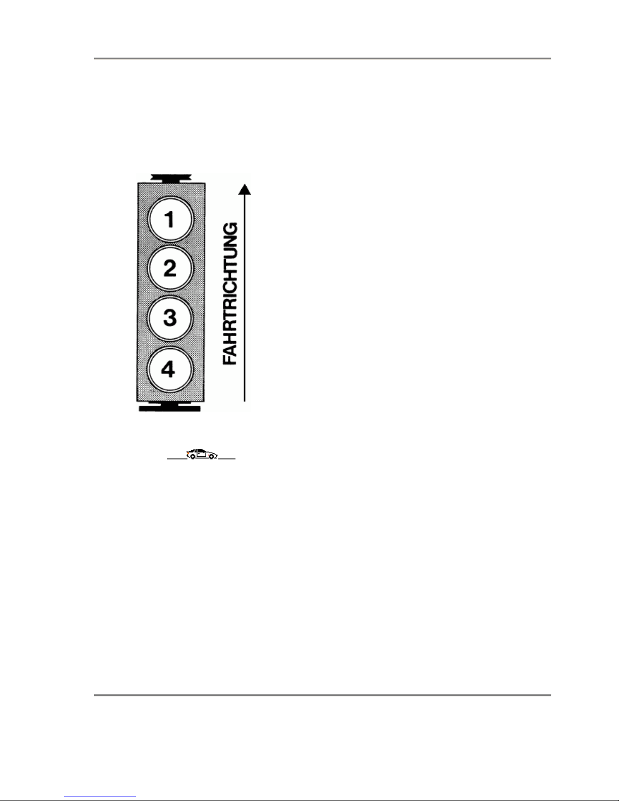
G e n e r a l 9 4 4
DESIGNATION OF CYLINDERS
0.7 Technical Data Printed in Germany

9 4 4 E n g i n e / C r a n k c a s e
10
TOLERANCES AND WEAR LlMITS
C o o l i n g S y s t e m
New Part Wear Limit
Thermostat
Radiator cap
High pressure valve
Low pressure valve
Opening temperature
Opening pressure
Opening pressure
81 - 85 °C
(178 - 185 °F)
1
+ 0.15
- 0.10
bar
(14,5
+ 2.1
- 1.5
psi)
0.1 bar
(1 .5 psi)
O i l C i r c u i t
Oil consumption
Oil pressure at 80° C (176° F)
oil temperature and at 5000 rpm
Oil dipstiek
Upper mark
Lower mark
ltr./1000 km
(600 mi./US qt)
Pressure
Capacity
Capacity
approx. 4 bar
(58 psi)
5.5 ltr. (5.8 US qt)
4.2 ltr. (4.4 US qt)
approx. 1.5
V a l v e T i m i n g
Camshaft bore
Camshaft
Camshaft
Cam follower bore in camshaft
housing
Cam follower
Camshaft
Inside dia.
Diameter
End play
Inside dia.
Diameter
Runout
60.5
+ 0.03
- 0
60.5
- 0.04
+ 0.055
0.10 - 0.18
38
+ 0.027
+ 0.007
38
- 0.018
- 0.034
0.02
Printed in Germany - I, 1982 Tolerences and Wear Limits
10 - 01

10
E n g i n e / C r a n k c a s e 9 4 4
TOLERANCES AND WEAR LlMITS
C y l i n d e r H e a d a n d V a l v e s
New Part Wear limit
Mating surface
Valve seat:
Intake
Exhaust
Intake
Exhaust
Outer correction angle
Inner correction angle
Valve guides:
Intake and exhaust
Valve stem:
Intake
Exhaust
Valve guide/valve stem
Intake
Exhaust
Compression
Distortion
Width
Width
Seat angle
Seat angle
Inside dia.
Diameter
Diameter
Clearance
Pressure
1.7
2.0
45°
45°
30°
60°
9 + 0.015
8.97 - 0.012
8.95 - 0.012
0.8
0.8
10 bar (145 psi)
or more
max. 0.08
10 - 02 Tolerences and Wear Limits Printed in Germany

9 4 4 E n g i n e / C r a n k c a s e
10
TOLERANCES AND WEAR LlMITS
P i s t o n s a n d C o n n e c t i n g R o d s
New Part Wear Limit
Cylinder/piston
Piston rings
Clearance
Side clearance
Groove 1
Groove 2
Groove 3
0.008 - 0.032
Mahle KS
0.05 -
0.082
0.04 -
0.072
0.023 -
0.137
0.05 -
0.082
0.05 -
0.082
0.023 -
0.137
approx. 0.080
Piston rings
Connecting rod bushing
Piston pin
Connecting rod bushing/
piston pin
End gap
Diameter
Diameter
Radial play
Groove 1 =
Groove 2 =
Groove 3 =
0.20 - 0.45
0.20 - 0.45
0.38 - 1.40
24
+ 0.018
+ 0.028
24 - 0.004
0.018 - 0.032
C r a n k s h a f t a n d E n g i n e B l o c k
Crankshaft
Connecting rod bearing journal
Connecting rod bearing/
crankshaft
Crankshaft bearing journal
Crankshaft bearing/crankshaft
Cylinder bore
Bore for balance shaft
bearing shells in crankcase
and balance shaft cover
Bore for bushing in bearing
housing
Balance shaft
Runout
Diameter
Radial play
End play
Diameter
Radial play
End play
Out-of-round
Diameter
Diameter
Diameter
0.04 - 0.06
51.971 - 51.990
0.034 - 0.092
0.100 - 0.400
69.971 - 69.990
0.020 - 0.098
0.110 - 0.312
0.010
35.000 - 35.019
34.000 - 34.019
30.975 - 30.991
max. 0.08
0.40
0.020
Printed in Germany - I, 1982 Tolerences and Wear Limits
10 - 02a

10
9 4 4
10 - 02b Blank Page

944 Engine, Crankcase
10
Tightening torques for engine
Location Thread Tightening torque Nm (ftlb)
Crankshaft/
Crankcase
Bolts - upper and lower
crankcase sections (studs)
Rotary body on
compensating shaft
M 12 x 1.5
M 10
M 8
M 6
M 6
30(22)
60° torque angle
20(15)
50(37)
20(15)
10(7.5)
10(7.5) secured
with Loctite
270
1st stage
2nd stage
1st stage
2nd stage
MODEL 82 - 85
Cover for compensating
shaft housing to upper
crankcase section
Hexagon head screw
Stud
M 6
M 8
M 8
8(6)
15(11)
20(15)
15(11)
30(22)
1st stage
2nd stage
1st stage
2nd stage
MODEL 85 ONWARD
Compensating shafts with
separate bearing bridges:
Bearing bridges (nuts) of
compensating shafts to
upper crankcase section
Cover for
compensating-shaft
housing to upper
crankcase section
Hexagon head screw
M 8
M 6
M 8 x 55
15(11)
33(24)
10(7.5)
15(11)
20(15)
1st stage
2nd stage
1st stage
2nd stage
MODEL 87 ONWARD
Hexagon head screw
(bearing bridge) for
compensating-shaft
housing to upper
crankcase section
Bearing housing left and
right to upper crankcase
section
M 8 x 58
M 8
15(11)
33(24)
20(15)
1st stage
2nd stage
Tightening torques for engine
Printed in Germany - XIX, 1989
10 - 03
10
Engine/Crankcase 944

Location Thread Tightening torque Nm (ftlb)
Con rod bolt Verbusrip
nut
Con rod bolt with smooth
contact surface
Water drain plug in upper
crankcase section
Oil pan to crankcase
Oil pan insert to oil pan
Oil drain plug
Engine supports left +
right to crankcase
Flywheel to crankshaft
Sensor holder to
crankcase
Toothed gear to
crankshaft
Sensor to holder
Pulley to toothed gear
Toothed gear to
compensating shaft
Tension pulley to bearing
Housing
Water pump to crankcase
Idler pulley to
water-pump housing
Tensioning pulley to
oil-pump housing
Oil pump to crankcase
Belt tensioner to
Crankcase
M 10 x 1.25
M 10 x 1.25
M 8
M 6
M 5
M 20 x 1.5
M 10
M 10 x 1.25
M 8
M 16 x 1.5
M 6
M 6 x 25
Tensile strength
10.9
M 10
M 10
M 6
M 10
M 10
M 6
M 10
M 8
75(55) + 5(4)
57(42) + 5(4)
20(15)
hand tight
4(3)
10(7.5)
1st stage
2nd stage
3rd stage
6(4.5) secured with Loctite 270
50(37)
48(35)
90(66)
20(15)
210(155)
8(6)
13(9.5)
45(33)
45(33)
8(6) secured with Loctite 270
45(33)
45(33)
8(6)
45(33)
20(15)
10 - 04 Tightening torques for engine
Printed in Germany - XIX, 1989

944 Engine/Crankcase
10
Location Thread Tightening torque Nm (ftlb)
Tensioning pulley to belt
Tensioner
Fastening - belt cover
Console for generator to
Crankcase
Remote thermometer
Sensor
Temperature sensor
(NTC II)
Oil pressure sensor
Housing insert in
oil-pump housing
Cooler
housing/thermostat
housing to crankcase
Sealing plug to
oil/water-cooler housing
Coolant bleeder screw
Pressure-relief valve
Oil filter
Oil separator to crankcase
Cylinder head
Cylinder head fastening
to upper crankcase
Section
Intake tube to cylinder
head
Inlet connectors - heating
to cylinder head
Connector for water pipe
Camshaft housing to
cylinder head
Aluminium sealing plugs
to camshaft housing
Camshaft bearing to
camshaft housing
M 10
M 6
M 10
M 10 x 1
M 12 x 1.5
M 18 x 1.5
M 6
M 8
M 18 x 1.5
M 8 x 1
M 20 x 1.5
M 8
M 8
M 8
M 8
M 8
M 18 x 1.5
M 6
45(33)
8(6)
45(33)
35(26)
15(11)
35(26)
8(6) mating surface sealed
with Loctite 574
20(15)
35(26)
12(9) + 3(2)
45(33)
20(15)
20(15)
Refer to Page 15 - 10 a
20(15)
20(15)
20(15)
20(15)
40(29.5)
8(6)
Tightening torques for engine
Printed in Germany - XIX, 1989
10 - 05

10
Engine/Crankcase 944
Location Thread Tightening torque Nm (ftlb)
Camshaft pulley to
camshaft Allen screw
Screw with internall
serrations
Console to camshaft
bearing
Connector to driver
Distributor rotor to
connector
Transport strap to
Cylinder head
Spark plugs
Fuel system
Fastening - diaphragm
damper and pressure
regulator to fuel
collection pipe
Cap nut to fuel collection
pipe
Exhaust system
Sealing nut to catalytic
convertor
All other screws and nuts:
M 10
M 10
M 6
M 5
M 4
M 6
M 14 x 1.25
M 16 x 1.5
M 12 x 1.5
M 14x 1.5
M 6
M 8
M 10
45(33)
65(48) - 70(52)
8(6)
5(4) secured with Loctite 221
4(3) selt-locking
8(6)
25(18) - 30(22)
30(22)
12(9)
30(22)
8(6) + 2(1.5)
20(15) + 2(1.5)
40(29) + 5(4)
10 - 06 Tightening torques for engine
Printed in Germany - XIX, 1989

9 4 4 E n g i n e / C r a n k c a s e
10
TOOLS
No. Description Special Tool Remarks
1 Chain sling US 1105
Printed in Germany Removing and Installing Engine
10 - 1
10
E n g i n e / C r a n k c a s e 9 4 4
REMOVING AND INSTALLlNG ENGINE
( M a n u a l T r a n s m i s s i o n )
E n g i n e r e m o v e d f r o m u n d e r n e a t
h .
Clutch bell housing remains on engine.
R e m o v i n g
1. Set up hoist and lift car on the pick-up points.
2. Use fender covers.
3. Remove front wheels.
4. Disconnect battery ground cable.
5. Disconnect battery positive cable and push
through splash wall with the rubber grommet.
6. Disconnect two plugs for engine wire harness.
Remove wire clamps.
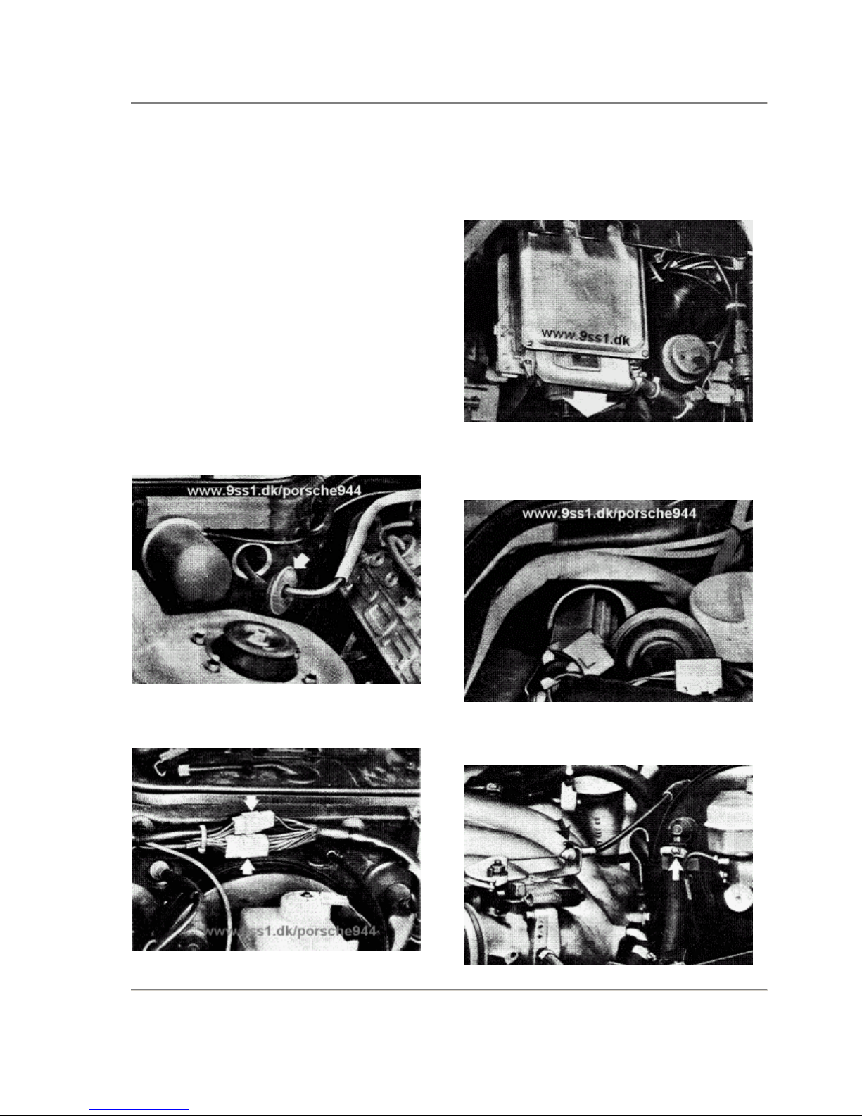
7. Pull off wire plugs on control unit (in area of
steering column).
8. Push wires and plugs through splash wall.
Detach bracket with sensor wire on intake pipe
to make engine removal easier.
9. Disconnect throttle operating cable. Disconnect
and pull off vacuum hose on brake booster.
10 - 2 Removing and Installing Engine Printed in Germany

9 4 4 E n g i n e / C r a n k c a s e
10
10. Disconnect air cleaner with air flow sensor on
body and on coolant hose, and lay aside.
11. Remove distributor cap, distributor rotor and
dust cap (to avoid damage).
12. Disconnect ground wire on splash wall.
13. Pinch fuel return line with a standard hose
clamp. Unscrew fuel feed line while
counterholding.
14. Unscrew fuel return line.
15. Attach Special Tool VW 10-222 on front
transport bracket of engine hold hold engine
tight in installed position.
16.
Open heater regu!ating valve. Remove cap on
coolant expansion tank.
17. Remove splash shield.
18. Remove exhaust assembly, by unscrewing
flange, exhaust manifold/exhaust pipe
connections and suspension points.
USA cars:
Also disconnect oxygen sensor plug and wire
in metal lug on firewall.
Printed in Germany - III, 1983 Removing and Installing Engine 10 - 3
10
E n g i n e / C r a n k c a s e 9 4 4
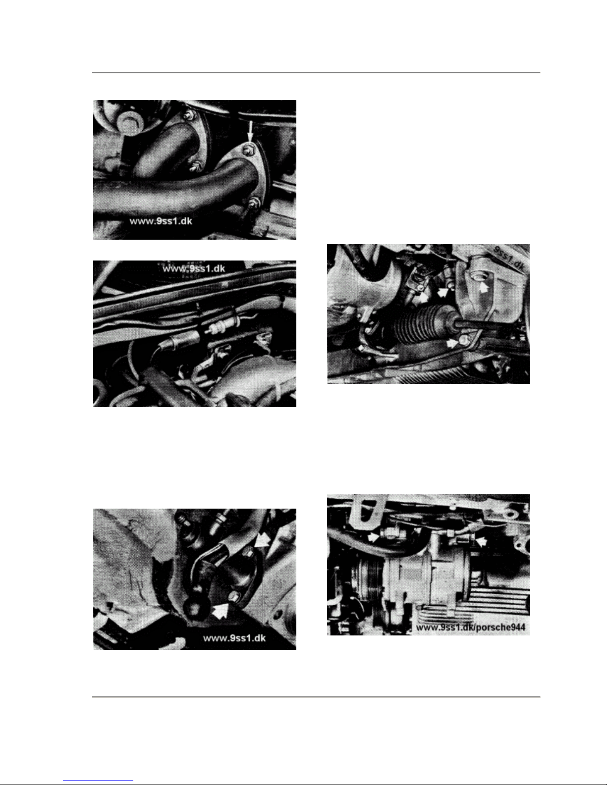
19. Disconnect electric wires for starter.
Unscrew and remove starter.
20. Unscrew clutch line clamp on engine.
21. Unscrew clutch slave cylinder on clutch
housing (line remains connected).
22. Unscrew stabilizer on body and control arms,
and remove.
23.
Unscrew shield for right engine mount on front
axle cross member.
24. Unscrew universal joint on steering gear, tie
rods on steering arms, upper hydraulic engine
mount on engine braces, left and right control
arms on front axle cross member, and remove
front axle cross member with steering from
underneath.
25. Cars with Air Conditioner:
Unscrew poly-rib belt tensioner and take off
belt.
26. Unscrew compressor on console (don't
disconnect refrigerant hoses). Suspend
compressor from the spring strut with a pjece
of wire.
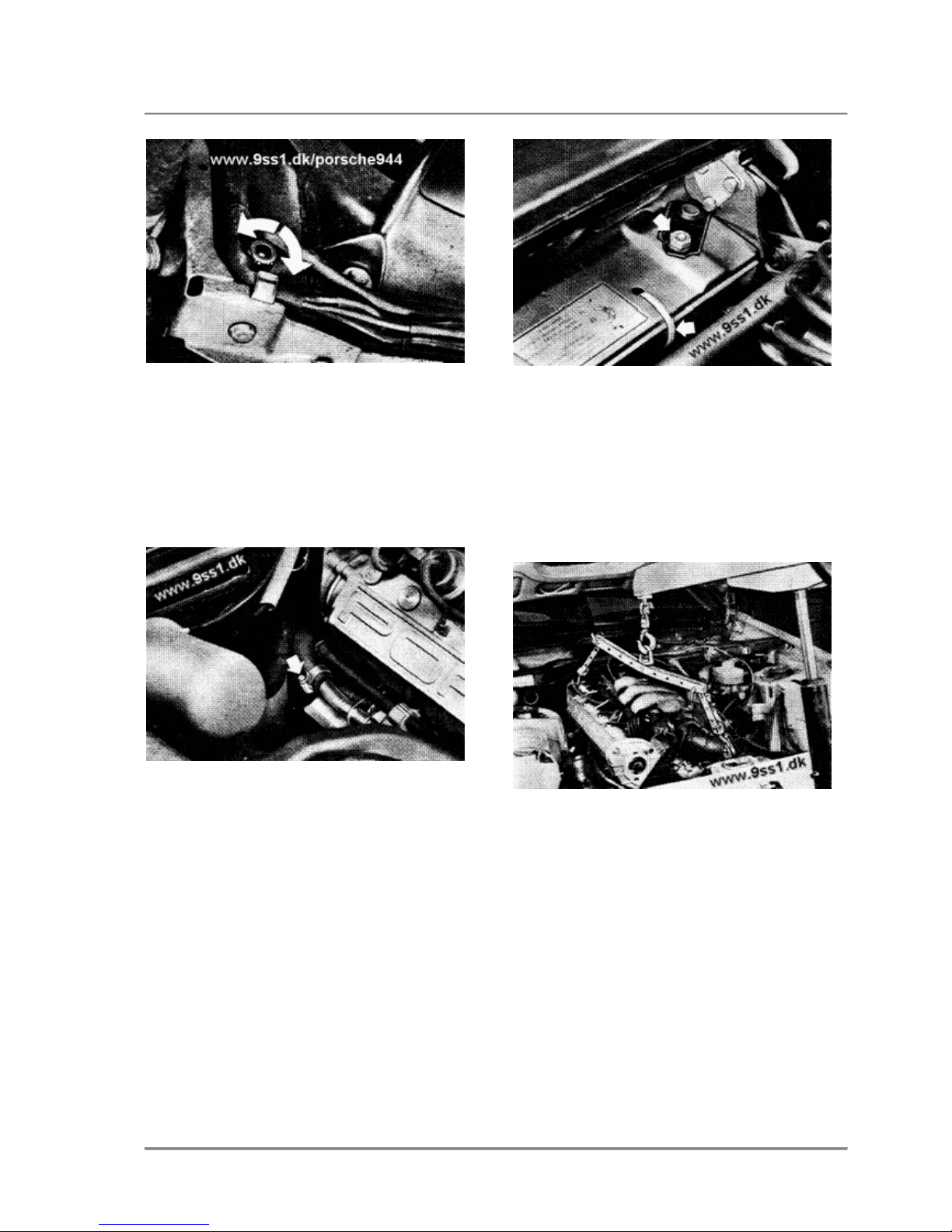
27. Drain coolant through drain plug bore in
radiator or the coolant hose and catch coolant.
10 - 4 Removing and Installing Engine Printed in Germany
9 4 4 E n g i n e / C r a n k c a s e
10
28. Remove coolant hose on bottom of radiator.
29. Remove upper central tube mounting bolts.
30. Lower car.
31. Remove coolant hose on heater valve.
32. Remove coolant return hose for heater.
33. Remove coolant feed hoses on expansion
tank.
34. Remove A/C fast idle hose.
35. Remove charcoal venting hose.
36. Remove vacuum line to vent valve and
vacuum
line to thermo valve at back of engine.
37. Remove upper radiator hose.
38. Remove radiator vent hose.
39. Remove wiring to temperature switch and both
cooling fans.
40.
Remove top radiator brackets and lift out
radiator with cooling fans.
41. Attach Special Tool US 1105 on engine
(shorter end towards rear of engine).
42. Lift engine slightly and remove VW 10-222.
43. Remove lower central tube mounting bolts.
44. Lower engine. pull forward and remove from
underneath.
Printed in Germany Removing and Installing Engine
10 - 5

10
E n g i n e / C r a n k c a s e 9 4 4
I n s t a l l i n g
Note the following for installation.
1. First insert transaxle/clutch housing mounting
bolts, but do not tighten.
N o t e
Only tighten mounting bolts to final torque after
Hydraulic engine mount and front axle cross member
have been mounted.
Torque for mounting bolts: 42 Nm (30 ft lb).
Front wheel alignment need not be checked after
removal and installation of engine.
2. Make sure radiator fits correctly in rubber mounts.
3. Secure coolant hose (between radiator and
expansion tank) on lock carrier with two straps.
4. Tighten bolts and nuts to specified torque.
5. Fill and bleed cooling system (see page 19-1).
10 - 6 Removing and Installing Engine Printed in Germany
 Loading...