

Page 1

Operator’s Manual
DuraChill™ Air- and Water-Cooled Chillers
5, 7.5 and 10 HP
110-279 26 June 2013
Page 2

Table of Contents
Introduction............................................................................................................................................................ 4
Standard and Optional Features ......................................................................................................................... 4
Standard Features ........................................................................................................................................... 4
Optional Features............................................................................................................................................. 4
General Safety Information.................................................................................................................................. 5
Safety Recommendations.................................................................................................................................... 6
Regulatory Compliance and Testing ................................................................................................................... 7
Unpacking............................................................................................................................................................ 7
Controls and Components...................................................................................................................................8
Control System .................................................................................................................................................... 8
Control Panel ................................................................................................................................................... 8
Power Switch / Disconnect .............................................................................................................................. 8
Temperature Probe .......................................................................................................................................... 8
Flow Sensor ..................................................................................................................................................... 8
Flow Switch ...................................................................................................................................................... 8
Fluid Pressure Sensor ..................................................................................................................................... 8
Refrigerant Pressure Switches ........................................................................................................................ 8
Fan Cycling Switch........................................................................................................................................... 9
Reservoir Float Switch (Optional) .................................................................................................................... 9
Fluid Circulation System ...................................................................................................................................... 9
Evaporator........................................................................................................................................................ 9
Reservoir Tank................................................................................................................................................. 9
Sight Glass or Level Indicator .......................................................................................................................... 9
Pump................................................................................................................................................................ 9
Full Flow Bypass .............................................................................................................................................. 9
Y-Strainer ......................................................................................................................................................... 9
External Bypass / Shutoff Valves..................................................................................................................... 9
Process Side Stream Filter System (Optional) ................................................................................................ 9
Cooling System.................................................................................................................................................... 9
Common Cooling System Components........................................................................................................... 9
Evaporator...................................................................................................................................................... 9
Compressor.................................................................................................................................................... 9
Filter Dryer...................................................................................................................................................... 9
Sight Glass ..................................................................................................................................................... 9
Thermostatic Expansion Valve (TXV) ............................................................................................................ 9
Hot Gas Bypass Solendoid Valve ................................................................................................................ 10
Refrigerant Safety Relief Valve .................................................................................................................... 10
Air-Cooled Chillers (DA Models) .................................................................................................................... 10
Condenser.................................................................................................................................................... 10
Condensing Fan........................................................................................................................................... 10
Water-Cooled Chillers (DW Models).............................................................................................................. 10
Brazed Plate Heat Exchanger / Condenser ................................................................................................. 10
Condensing Water Regulating Valve ........................................................................................................... 10
Receiver ....................................................................................................................................................... 10
Component Identification................................................................................................................................... 11
Front - All Models ........................................................................................................................................... 11
5 HP and 7.5 HP Chillers - Rear .................................................................................................................... 11
10 HP Chillers - Rear ..................................................................................................................................... 12
Installation and Startup ...................................................................................................................................... 13
Site Requirements ............................................................................................................................................. 13
Ambient Temperature and Relative Humidity ................................................................................................ 13
Location.......................................................................................................................................................... 13
Clearance....................................................................................................................................................... 13
Electrical Power ................................................................................................................................................. 14
Signal Inputs/Outputs ........................................................................................................................................ 15
Remote On / Off ............................................................................................................................................. 15
110-279 1
Page 3

Alarm Output .................................................................................................................................................. 15
RS-232/RS-485 Serial Output........................................................................................................................ 15
External Piping................................................................................................................................................... 16
General Considerations ................................................................................................................................. 16
Process Fluid Connections ............................................................................................................................ 16
Facility Water Connections ............................................................................................................................ 16
Reservoir Drain .............................................................................................................................................. 16
Reservoir Vent ............................................................................................................................................... 16
Full Flow Bypass ............................................................................................................................................ 17
Process Coolant ................................................................................................................................................ 18
Suitable Fluids................................................................................................................................................ 18
Startup ............................................................................................................................................................... 19
Facility Water Flow (water-cooled units only) ................................................................................................ 19
Filling the Reservoir ....................................................................................................................................... 19
Starting Process Fluid Flow ........................................................................................................................... 20
Normal Operation................................................................................................................................................ 21
Power On........................................................................................................................................................... 21
Temperature Unit (°C or °F) Selection / Factory Default Reset ........................................................................ 21
Adjusting the Set Point Temperature................................................................................................................. 22
Selecting the Pressure / Flow Rate Display and Units ...................................................................................... 22
Displaying Internal (P1) and External (P2) Probe Temperatures...................................................................... 22
Setting Operational Parameters / Limits............................................................................................................ 22
High Temperature Limit (HL) ......................................................................................................................... 25
Low Temperature Limit (LL)........................................................................................................................... 25
High Ambient Temperature Limit (HA)........................................................................................................... 26
Maximum Fluid Pressure (FP) ....................................................................................................................... 26
Minimum Flow Rate (FL)................................................................................................................................ 26
Lower Band (Lb)............................................................................................................................................. 27
Upper Band (Ub) ............................................................................................................................................ 27
Remote Probe (rP)......................................................................................................................................... 27
Calibration Offset (C1 / C2 / C3) .................................................................................................................... 27
Compressor Delay (Cd) ................................................................................................................................. 28
Flow Rate Calibration (Fc) ............................................................................................................................. 28
Coolant Density (dS)...................................................................................................................................... 28
Specific Heat (Sh) .......................................................................................................................................... 28
Current Control (CC)...................................................................................................................................... 28
Communications Baud Rate (PC).................................................................................................................. 29
Low Ambient Temperature Limit (LA) ............................................................................................................ 29
Password (Pd)................................................................................................................................................ 29
HGB Valve Delay (td)..................................................................................................................................... 29
Fuse Bits (Fb)................................................................................................................................................. 29
Enabling / Disabling the Local Lockout.............................................................................................................. 30
Display, Alarm and Error Messages..................................................................................................................31
Automatic Restart from Alarm Mode ................................................................................................................. 33
Routine Maintenance..........................................................................................................................................34
Recommended Routine Maintenance Schedule ............................................................................................... 34
Reservoir Coolant Level .................................................................................................................................... 34
Coolant Freeze Protection ................................................................................................................................. 34
Inline Strainer..................................................................................................................................................... 34
Air Filters............................................................................................................................................................ 35
Troubleshooting.................................................................................................................................................. 36
Troubleshooting Chart ....................................................................................................................................... 36
Compressor Overload Fault (Ft20).................................................................................................................... 37
Low Pressure Sensor..................................................................................................................................... 37
High Pressure Sensor.................................................................................................................................... 37
Technical Information......................................................................................................................................... 38
110-279 2
Page 4

Chiller Specifications ......................................................................................................................................... 38
Air-Cooled Chillers (DA500, DA750, DA1000) .............................................................................................. 38
Water-Cooled Chillers (DW500) .................................................................................................................... 38
Electrical Specifications ..................................................................................................................................... 39
DA500 Chillers ............................................................................................................................................... 39
DW500 Chillers .............................................................................................................................................. 40
DA750 Chillers ............................................................................................................................................... 41
DA1000 Chillers ............................................................................................................................................. 41
Pump Performance............................................................................................................................................ 42
RS-232 Serial Communications (RS-485 Option) ............................................................................................. 43
Equipment Disposal (WEEE Directive) ............................................................................................................. 44
Service and Technical Support.......................................................................................................................... 44
PolyScience Chiller Fluids ................................................................................................................................. 45
Warranty............................................................................................................................................................... 45
Appendix.............................................................................................................................................................. 46
Flow Schematic – Air-Cooled Chillers ............................................................................................................... 46
Flow Schematic - Water-Cooled Chillers........................................................................................................... 47
Wiring Diagram - 5 HP and 7.5 HP Air-Cooled Chillers .................................................................................... 48
Wiring Diagram - 10 HP Air-Cooled Chillers...................................................................................................... 49
Wiring Diagram - 5 HP Water-Cooled Chillers .................................................................................................. 50
4-20 mA Set Point Control................................................................................................................................. 51
110-279 3
Page 5

Introduction
The PolyScience line of DuraChill Chillers provide cooling power for demanding applications and serve as an
economical alternative to tap water cooling systems. All models feature a microprocessor-based controller,
digital Temperature Display (°C or °F), one-touch set point display, and digital Pressure/Flow Rate Display (PSI,
kPa, GPM, LPM) with push-button selection.
Standard and Optional Features
DuraChill Chillers offer exceptional performance, reliability, and operational simplicity. Available in both air- and
water-cooled models, these robust self-contained Chillers are engineered to provide accurate temperature
control in a broad range of process cooling applications.
These powerful Chillers can be configured with a wide variety of standard and optional features, including:
Standard Features
• Process temperature range: 32° to 86°F (0° to 30°C)
• Ambient temperature range: 60° to 104°F (16° to 40°C)
• Temperature stability: ±2.0°F (±1.1°C)
• High efficiency vertical air exhaust
• Accurate microprocessor control with digital LED readout
• Pump protection by means of a Full Flow Bypass Valve
• Copeland Scroll compressor
• Compressor protection through high and low refrigerant pressure cuto
• RS-232 communications interface
• Reservoir sight glass
• Remote On / Off control (dry con
• Dry contact status alarm output
• Power phase monitor on 3-phase units
• Heavy-duty locking casters for easy maneuverability
• Stainless steel c
®
uts
r- and under-temperature alarms • Process protection provided by ove
tact)
entrifugal pump (1 HP on 5 and 7.5 HP units; 2 HP on 10 HP units)
O t
p ional Features
• Other centrifugal and turbine pump
s
• RS-485 communications interface
• Remote On / Off control
(24 VDC)
• Process shutoff valves
• External bypass valve
• Stainless steel reservoir
• Heaters
• Feet to replace casters
• Reservoir level float switch
• Side stream filter assemblies
• External inlet / outlet filter assemblies
• Deionized compatible process plumbing
Configuration Data Sheet showing how your DuraChill Chiller is equipped is included with the manual if
A
applicable (see inside front cover).
110-279 4
Page 6
General Safety Information
When installed, operated, and maintained according to the directions in this manual and common safety
procedures, your DuraChill Chiller should provide safe and reliable temperature control. Please ensure that all
individuals involved in the installation, operation, or maintenance of this Chiller read this manual thoroughly prior
to working with the unit.
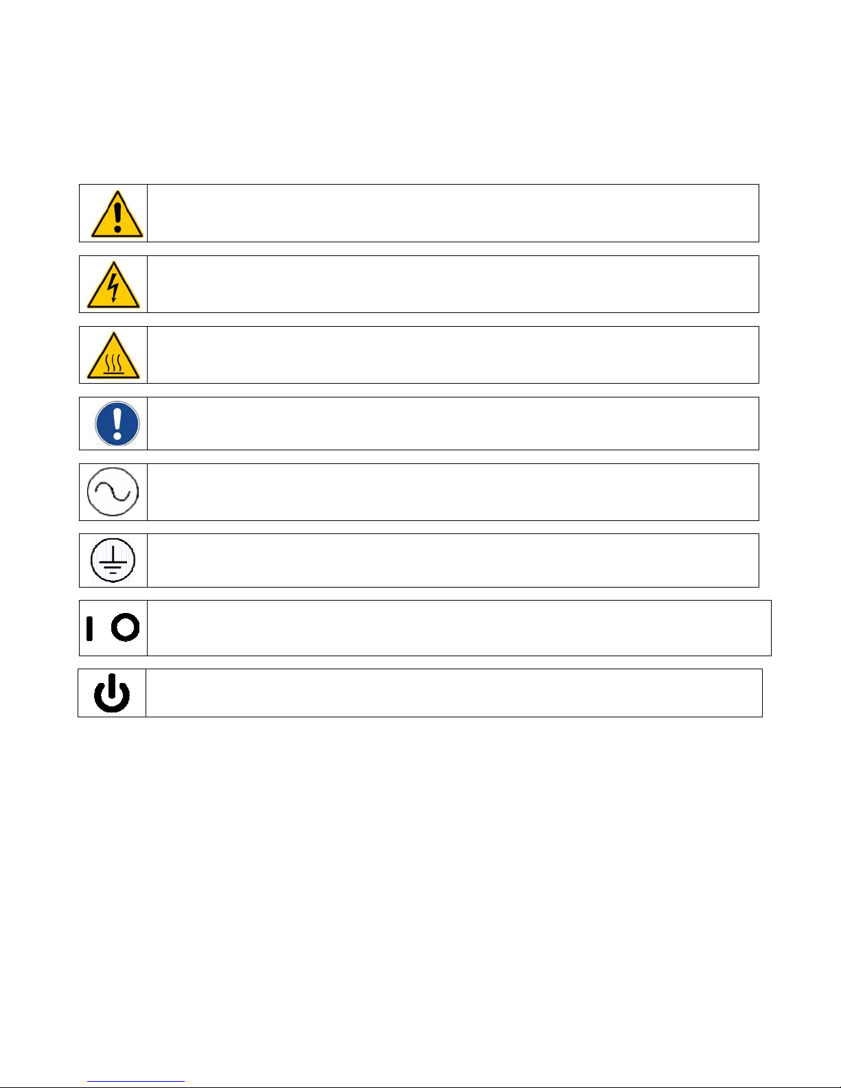
This symbol alerts you to wide range of potential dangers.
This symbol advises you of danger from electricity or electric shock.
This symbol indicates that a hot surface may be present.
This symbol marks information that is particularly important.
/
This symbol indicates alternating current.
This symbol indicates a protective conductor terminal. Only connect the unit to a power socket with earth
(ground) contact (PE – protective earth). The power supply connector plug serves as a safe disconnecting
device from the line and must always be easily accessible.
These symbols on the Power Switch / Disconnect indicate that they place the main power supply ON / OFF.
This symbol on the Power Button indicates that it places the unit in a standby mode. It DOES NOT fully
disconnect the unit from the power supply.
Read all instructions pertaining to safety, set-up, and operation.
Proper operation and maintenance is the user’s responsibility.
110-279 5
Page 7
Safety Recommendations
It is the user’s responsibility to read and understand all instructions and safety precautions included in this
manual prior to installing or operating this equipment. Contact our Customer Service Department with any
questions regarding the operation of this Chiller or the information contained in this manual.
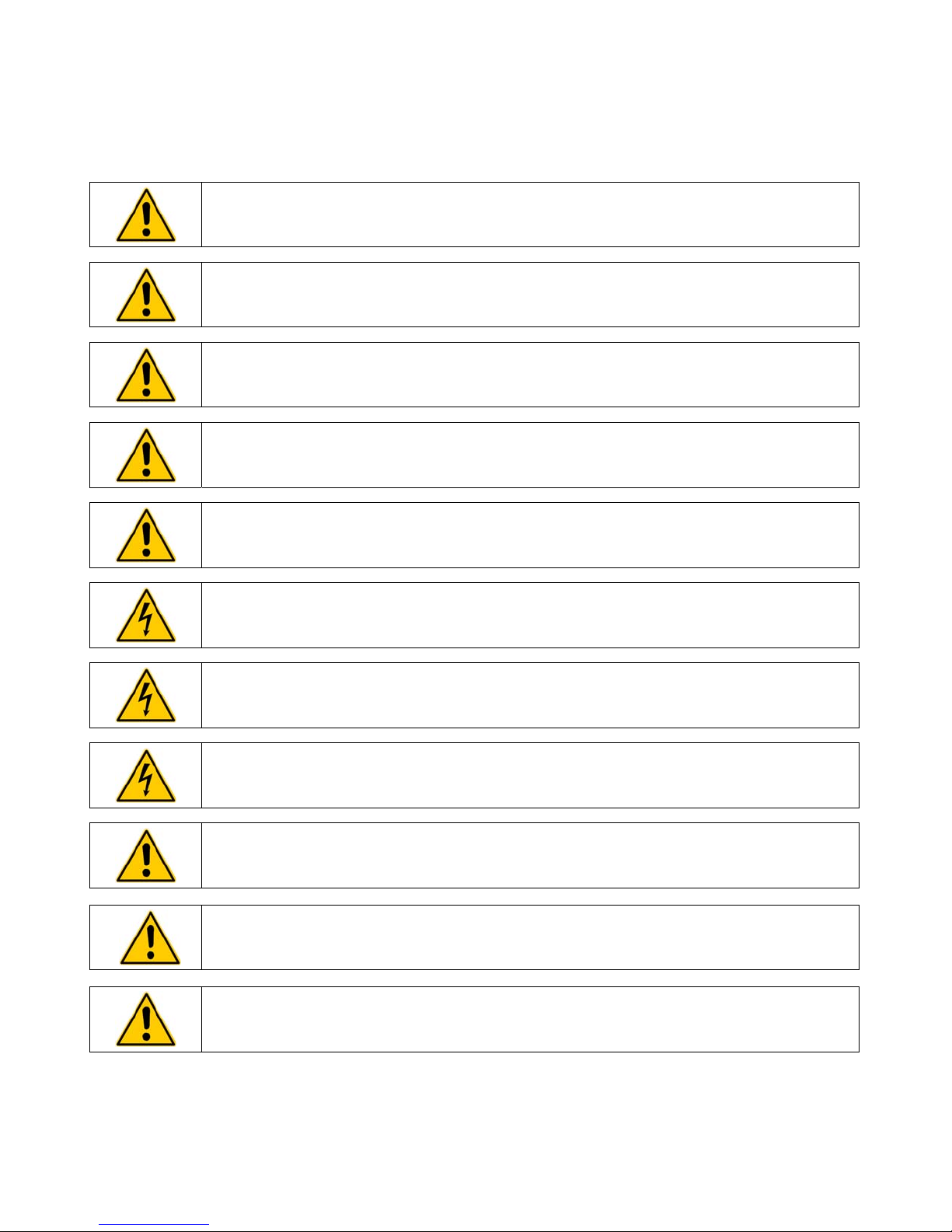
WARNING: All warning labels should be carefully observed. Never remove or obstruct a warning label.
WARNING: Installation, operation, or maintenance of this equipment should be performed in strict
accordance with the instructions outlined in this manual. Failure to follow those instructions may
increase the risk of personal injury, damage the equipment, and/or void the warranty.
WARNING: Be sure to remove power from the equipment, reclaim the refrigeration charge, and relieve
any residual pressure before cutting into the refrigeration system.
WARNING: Do not attempt to operate leaking or damaged equipment.
WARNING: Service should only be performed by fully qualified personnel. Extreme caution is required
as hazards are present when servicing this equipment.
WARNING: Do not attempt to override the power interlock switch or any other safety feature on this
equipment.
WARNING: Disconnect electrical power before moving unit. Keep unit upright when moving. Always
follow your company’s procedures and practices regarding safe lifting and relocation of heavy objects.
WARNING: Make sure the equipment’s main power switch is in the OFF position before connecting or
disconnecting power. Follow all applicable electrical and safety codes and procedures when connecting
power to the unit. Electrical connections should be made by an authorized electrical installer.
WARNING: This equipment must be properly filled with cooling fluid before use and properly drained
before moving or service.
WARNING: Use only fluids that comply with safety, health, and equipment compatibility requirements.
Read the safety data sheet for the fluid being used carefully before use.
CAUTION: Always operate this equipment within the stated design specifications.
110-279 6
Page 8

Regulatory Compliance and Testing
CSA UL (5 HP 60Hz units)
CAN/CSA C22.2 No. 61010-1-04 — Safety Requirements for Electrical Equipment for Measurement, Control
and Laboratory Use, Part I: General Requirements.
CAN/CSA C22.2 No. 61010-010-04 — Safety Requirements for Electrical Equipment for Measurement,
Control and Laboratory Use - Part 2-010: Particular Requirements for Laboratory Equipment for the Heating of
Materials.
UL Std No. 61010-1 (2
nd
edition) — Electrical Equipment for Laboratory Use, Part I: General Requirements.
CE (All 50Hz units)
EC Low Voltage Directive 2006/95/EC
EC Electromagnetic Compatibility Directive 2004/108/EC
IEC 61010-1-2001
IEC 61010-2-10 : 2005
IEC 61326-1:2005
Unpacking
Your Chiller is shipped in a special container. Retain the container and all packing materials until the unit is
completely assembled and working properly. Set up and run the unit immediately to confirm proper operation. If
the unit is damaged or does not operate properly, contact the transportation company, file a damage claim and
contact the company where your unit was purchased immediately.
110-279 7
Page 9
Controls and Components
Your DuraChill Chiller consists of three basic sub-systems:
• Control
• Fluid circulation
• Cooling
This section describes these sub-systems in detail and includes information on the available options. Please
note that your Chiller may or may not be equipped with all the components discussed.
Control System
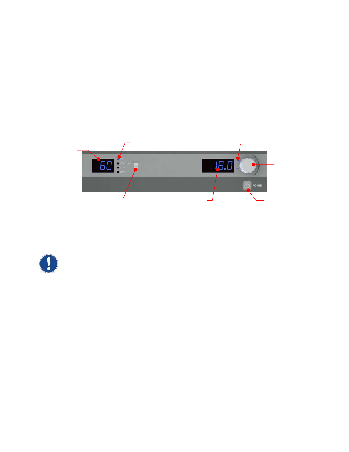
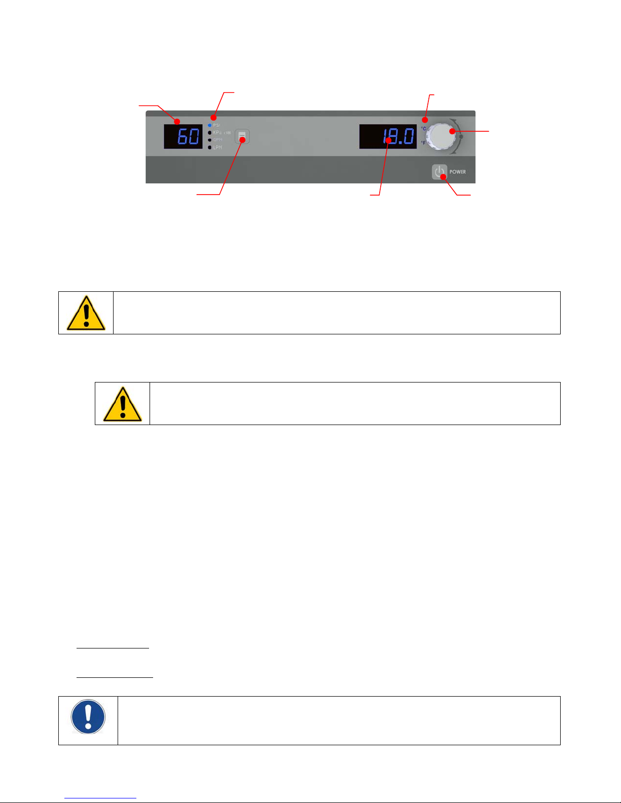
Control Panel — Temperature set point, temperature units, and other operating parameters are set via the
Control Panel. Operating information is displayed on a local digital readout.
Pressure / Flow
Rate Display
Units / Menu
Select Button
Pressure / Flow Rate Unit
Temperature
Display
Power Switch / Disconnect — The main power switch is located on the front door of the Chiller. This switch
also functions as a power disconnect when access to the unit’s components and terminal blocks is required; the
access door cannot be opened until the Power Switch / Disconnect is placed in the OFF position.
Temperature Unit
Select / Set Knob
Power Button
NOTE: Loss of Power – In the event that power is lost while the Chiller is operating, the unit will
automatically resume operation when the power is restored. If the unit was in Standby mode when power is
lost, it will power up in Standby mode. The above is also true if power is removed via the Power Switch /
Disconnect.
Temperature Probe — An internal RTD is used to measure fluid temperature downstream of the pump. Its
reading is displayed on the Control Panel’s LED temperature display.
Flow Sensor — Monitors process fluid flow. If the flow rate is less than the user-settable alarm value, power to
the pump, compressor, and fan is removed and an alarm message displayed on the Control Panel’s LED
readout.
Flow Switch — Requires a minimum of ~4 gpm (15.1 lpm) to close. If the flow rate is too low, the switch will
open and power to the pump, compressor, and fan removed; an alarm message will also be displayed on the
Control Panel’s LED readout.
Fluid Pressure Sensor — Measures fluid pressure at the pump outlet. If the fluid pressure exceeds the user-
settable alarm value, power to the pump, compressor, and fan is removed and an alarm message displayed on
the Control Panel’s LED readout.
Refrigerant Pressure Switches — When activated, these switches remove power to the pump, compressor,
and fan; an alarm message is also displayed on the Control Panel’s LED readout.
The Low Pressure Switch opens if the refrigerant pressure falls below 10 psi (0.7 bar) and closes if the
pressure is above 30 psi (2.1 bar). The Low Pressure Switch will auto-reset.
The High Pressure Switch opens if the refrigerant pressure exceeds 630 psi (43.4 bar). The High
Pressure Switch must be manually reset (see Troubleshooting, Compressor Overload Fault).
110-279 8
Page 10

Fan Cycling Switch — This switch control fan operation. The fan turns ON when the discharge pressure of the
refrigerant exceeds 400 psi (27.8 bar) and remains running until the pressure falls below 300 psi (20.7 bar).
NOTE: 10 HP Chillers have two fans. One fan turns ON with the compressor and runs continuously as long
as the compressor is ON; operation of the second fan is based on refrigerant pressure as described above.
Reservoir Float Switch (Optional) — Measures liquid level in the Chiller’s reservoir. If the fluid level drops too
low, power to the pump, compressor, and fan is removed and an alarm message displayed on the Control
Panel’s LED readout.
Fluid Circulation System
This sub-system governs fluid flow through the Chiller.
Evaporator — Serves as the heat exchanger between the refrigeration and fluid flow systems. Cools fluid
before it returns to process.
Reservoir Tank — This polyethylene tank is used to maintain stable temperature control and an adequate
reservoir of fluid for the system. It may be equipped with an optional float switch that monitors fluid level and
activates an alarm. A stainless steel reservoir is available as an option.
Sight Glass or Level Indicator — This indicator serves as a convenient means of checking the liquid level
within the Reservoir Tank. The sight glass is located on the rear panel.
Pump — Used to pump fluid from the Reservoir Tank to the process and back to the Chiller. A variety of pumps
are available for operation at different pressures, flow rates, and distances from the Chiller to the process.
Full Flow Bypass — Allows the maximum operating pressure to be regulated and protects the Pump in the
event that process piping becomes restricted or clogged. Diverts flow from the process line back to the
Evaporator and Reservoir.
Y-Strainer — Located on the inlet to the Chiller. Incorporates a cleanable 20 mesh (841 micron) stainless steel
screen to remove large particulate matter from the process fluid.
External Bypass / Shutoff Valves — Allows the unit to be operated independent of the process during the
servicing of process equipment and/or process lines. Can also be used to fine-tune process pressure and flow
rate.
Process Side-Stream Filter System (Optional) — Consists of a 50 micro filter and ball valve connected
between the Chiller inlet and outlet. It is used to filter particulate matter from a portion of the process fluid flow.
Cooling System
NOTE: The Condenser on DuraChill Chillers is either air-cooled or water-cooled.
Common Cooling System Components
The following components are common to both air-cooled (DA models) and water-cooled (DW models)
DuraChill Chillers:
Evaporator — Serves as the heat exchanger between the refrigeration and fluid flow systems. Removes heat
from the process fluid before it is returned to the process equipment.
Compressor — The Chiller incorporates a 5 to 10 HP Copeland Scroll compressor. The Compressor is
protected from overloads through high and low pressure cutouts.
Filter Dryer
— Removes residual particulate matter and moisture from the refrigeration system. The Filter Dryer
must be replaced whenever the sealed refrigeration lines are opened for service.
Sight Glass — Used to observe refrigerant fluid flow to the Evaporator.
Thermostatic Expansion Valve (TXV) — Controls refrigerant superheat at the outlet of the Evaporator to
prevent liquid from returning to the Compressor.
110-279 9
Page 11

Hot Gas Bypass Solenoid Valve — Injects refrigerant vapor into the Evaporator to help maintain a constant
temperature when the temperature of the process fluid falls below the temperature set point. Under low- and noload conditions, temperature continues to fall until it reaches the “Lb” lower band and shuts the Compressor
OFF.
Refrigerant Safety Relief Valve — This is an automatic safety used to vent refrigeration gas if it exceeds 650
psi (44.8 bar).
Air-Cooled Chillers (DA Models)
The following components are specific to air-cooled DuraChill Chillers:
Condenser — The Compressor pumps vapor into the Condenser at high pressure. As the surrounding air is
cooler than the hot vapor, heat energy passes into the air from the condenser coils.
Condensing Fan — a 1 HP fan (two fans on 10 HP units) that draws air over the condenser coils to cool
refrigerant gas. The standard fan cycles ON and OFF based on refrigerant pressure (ON at 400 psi / 27.6 bar;
OFF at 300 psi / 20.7 bar). The second fan on 10 HP units runs whenever the Compressor is ON.
Water-Cooled Chillers (DW Models)
Brazed-Plate Heat Exchanger / Condenser — Serves as the heat exchanger between the refrigeration system
and the facility water supplied by the customer. Removes heat from the refrigerant.
Condensing Water Regulating Valve — This valve regulates the facility water flow to maintain optimal
discharge pressure (approximately 250 psi / 17.2 bar) for the heat exchange in the Condenser. It increases flow
to decrease pressure and decreases flow to increase pressure.
Receiver — The main purpose of the Receiver is to temporarily store refrigerant (in its liquid state) that is not
required when load conditions are low. The Receiver also provides a constant supply of liquid to the
Thermostatic Expansion Valve (TXV).
110-279 10
Page 12
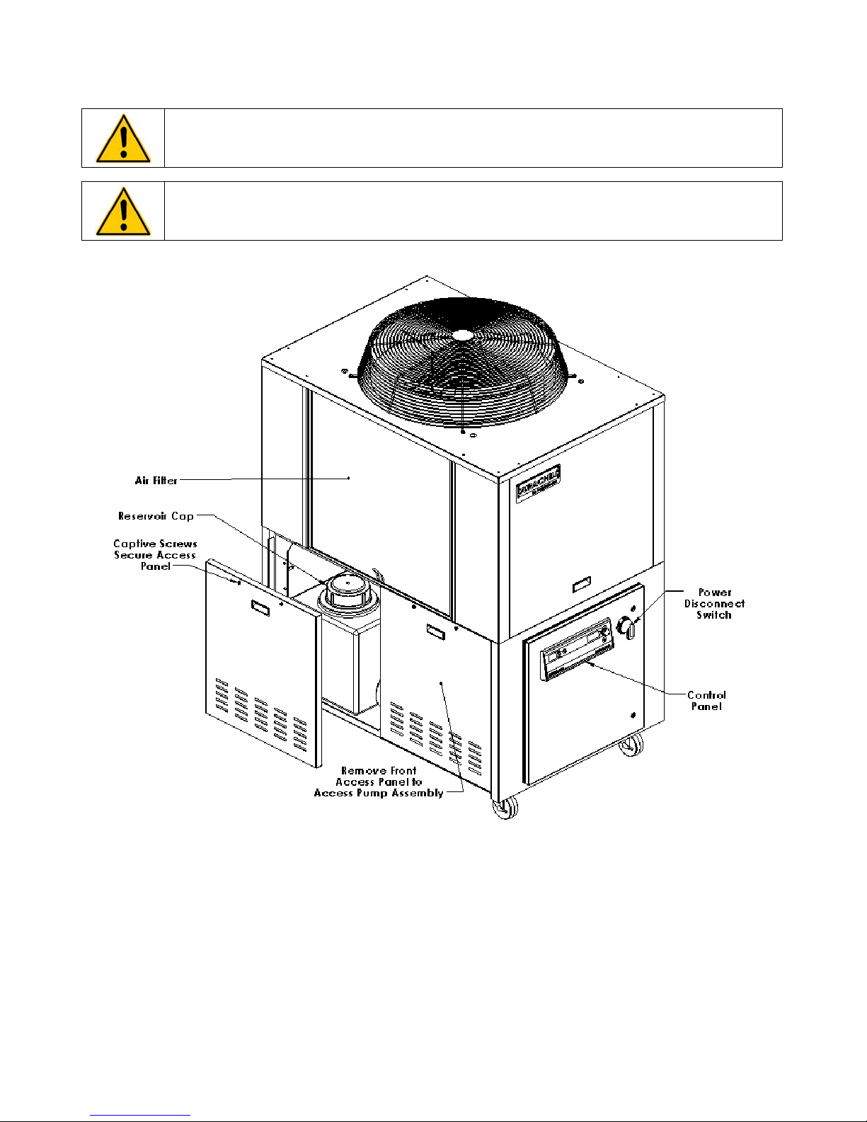
Component Identification
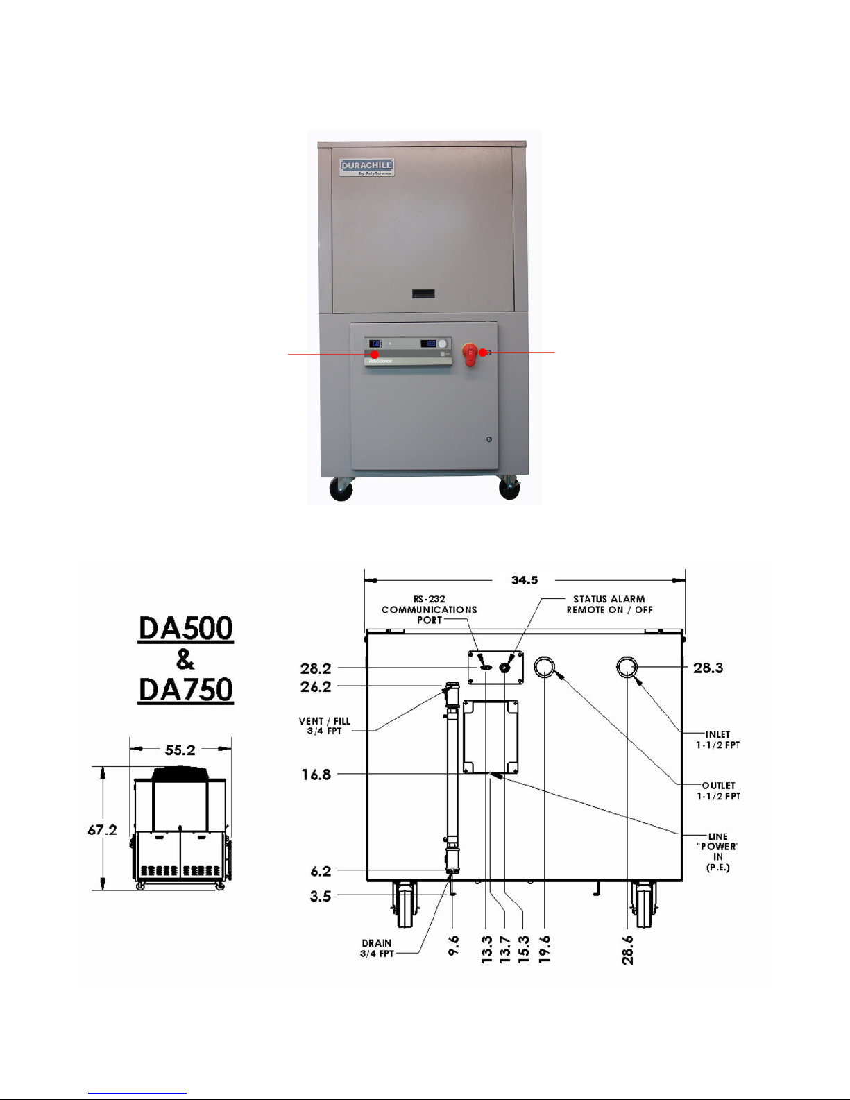
Front – All Models
Control Panel
5 HP and 7.5 HP Chillers – Rear
Power Switch / Disconnect
110-279 11
Page 13
10 HP Chillers – Rear
110-279 12
Page 14
Installation and Startup
WARNING: Be sure all power is OFF before proceeding.
Site Requirements
Ambient Temperature and Relative Humidity
The Chiller is designed for indoor installation in ambient temperatures between 60° and 104°F (16° and 40°C);
relative humidity should not exceed 80% (non-condensing).
Location
The Chiller should be installed on a strong, level surface capable of supporting 1050 lbs. / 476.3 kg (5 and 7.5
HP units) or 1500 lbs. / 680.1 kg (10 HP units).
It should be located as close to possible to the process requiring cooling and installed no closer than 4 feet (1.4
meters) to a heat-generating source, such as heating pipes, boilers, etc. If possible, the Chiller should be
located near a suitable drain to prevent flooding in the event of leaks. Do not place it where corrosive fumes,
excessive moisture, excessive dust, or high room temperatures are present.
For ease of positioning and maneuverability, the Chiller is supplied with casters. The front wheels can be locked
to keep the Chiller in place while in use.
To help prevent voltage drops, position the Chiller as close as possible to the power distribution panel. Avoid
voltage drops by using a properly grounded power source wired to meet electrical data plate requirements. The
use of an extension cord is not recommended.
NOTE: The Chiller may be located at a level below that of the equipment being cooled. As long as the
process remains closed, overflow will not occur when adding cooling fluid to the Chiller reservoir.
Clearance
Adequate clearance should be allowed on the front, sides, and rear of the Chiller for access to connections and
components. The front and rear vents of the Chiller must be a minimum of 24 inches (61 cm) away from walls or
vertical surfaces so air flow is not restricted.
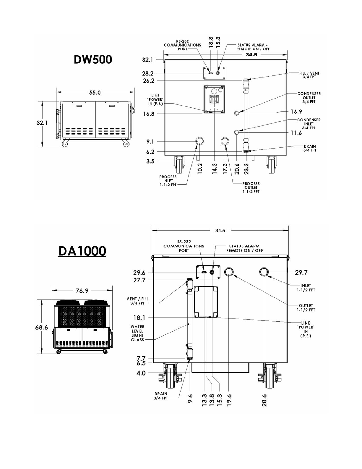
Overall Dimensions
Model Length Width Height
DA500 56 in. (142.2 cm) 34.5 in. (88 cm) 67 in. (170.2 cm)
DW500 56 in. (142.2 cm) 34.5 in. (88 cm) 32.1 in. (81.6 cm)
DA750 56 in. (142.2 cm) 34.5 in. (88 cm) 67 in. (170.2 cm)
DA1000 77 in. (195.6 cm) 34.5 in. (88 cm) 68.2 in. (173.2 cm)
110-279 13
Page 15
Electrical Power
WARNING: Make sure the main power switch is in the OFF position before connecting or disconnecting
electrical power from the unit. Follow all applicable electrical and safety codes and procedures when
connecting power to the unit. Electrical connections should be made by an authorized electrical installer.
WARNING:
Make certain that the electrical supply is the same voltage and frequency as your unit (see identification
label).
Make sure electrical connections comply with all applicable electrical codes.
Ground the Chiller in accordance with NEC Article 250.
Operating voltage must be within 10% of the data plate rating.
Phase imbalance must be below 5%.
WARNING: DO NOT apply power to the Chiller until the unit is ready for Startup
CAUTION: DO NOT apply power to the Chiller until the Reservoir has been filled. When Controller power
is turned ON, the pump automatically begins pumping. If the Reservoir has not been filled, the pump could
be damaged.
The Chiller is equipped with a phase monitor that prevents startup if phase sequence is incorrect. It will also turn
the Chiller OFF in the event of a loss of one phase and/or prevent Chiller operation if there is a voltage
mismatch between any two phases greater than 8%. Be sure to connect electrical lines in proper sequence, i.e.:
L1, L2, and L3.
There is a junction box on the rear of the unit to which you can connect the electrical power supply conduit. Be
sure to provide suitable conduit strain relief and grounding.
WARNING: DO NOT remove the ground wire while diagnosing any power supply problems.
110-279 14
Page 16
Signal Inputs/Outputs
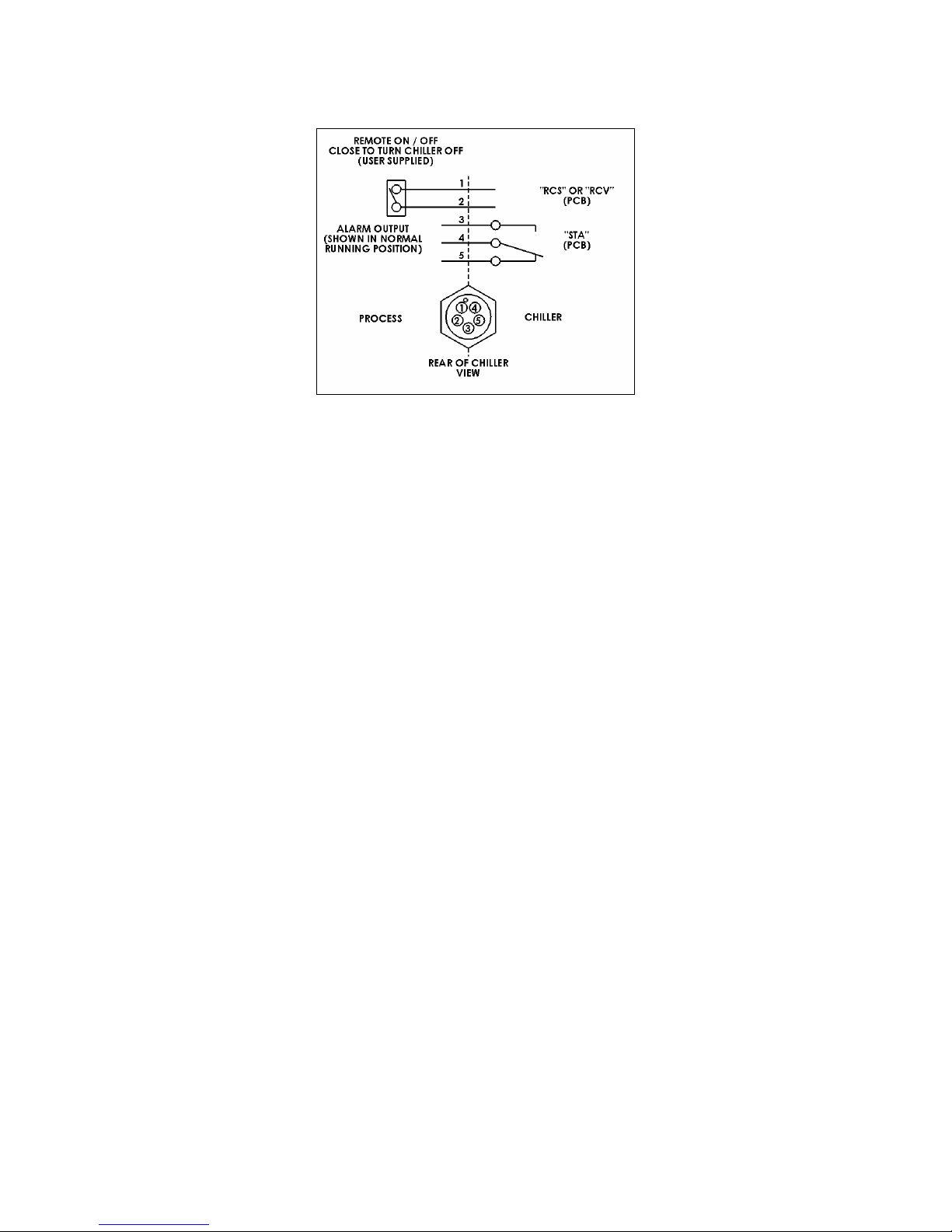
Remote On / Off and Alarm Output
Remote On / Off
This allows the operator to turn the Chiller ON and OFF using a remote dry contact. The Chiller is ON when the
contact is open; it is OFF when the contact is closed. A 10-ft (3 m) cord with 5-pin mating plug is provided.
Alarm Output
This allows the operator to connect a remote alarm device to the Chiller. The alarm output consists of normally
open (NO) and normally closed (NC) contacts which are switched whenever an alarm, fault, or error condition is
detected or when the Chiller is OFF. A 10-ft (3 m) cord with 5-pin mating plug is provided.
RS-232 Serial Communication (RS-485 Option)
This allows the operator to remotely control the Chiller and/or output temperature readings to an external
recorder or other auxiliary device. A 9-pin D-connector is provided on the rear of the instrument enclosure for
this connection.
The maximum communications distance for Chillers equipped with RS-232 is 50 feet (15 meters); the maximum
distance for units equipped with the RS-485 option is 4000 feet (1200 meters).
See the Technical Information section for serial communications protocol and commands.
110-279 15
Page 17
External Piping
WARNING: All facility water connections must be made by a licensed plumber.
General Considerations
To maintain a safe workplace and avoid leaks, special care should be taken when choosing hoses and
connectors for the Chiller. It is the user’s responsibility to ensure that the tubing and fittings connected to the
Chiller are compatible with the fluid, temperature, and pressure being used.
• Pressure Ratings – Hoses should be able to withstand a minimum pressure of 250 psi (17.2 bar).
• Flexible Tubing – Avoid tubing that will expand and increase fluid volume when operating at the desired
pressure.
• Take care when selecting hoses and connections for the Chiller. All external piping, tubing, or hoses should
be run full size to limit the potential for external pressure drops. The use of quick-connect fittings is not
recommended, as they can cause substantial pressure drops.
• Where applicable, always use a back-up wrench when making piping connections to the Chiller.
• Hose Diameter – The fittings on the Chiller’s process fluid lines are female 1.5 in NPT. The facility water
fluid inlets and outlets on water-cooled models are female 0.75 inch NPT.
• Facility Water (water-cooled models only) – Should be clean and well maintained. Ideally, the facility water
should be tested monthly to ensure a pH level between 7.2 and 7.8. Add algaecide if algae growth is
present.
Process Fluid Connections
The Chiller has two internally threaded (1.5 inch ID NPT) fittings on the rear of the instrument housing for the
process water connections.
Connect the Chiller’s inlet and outlet to the external apparatus with hoses or pipes. The direction of the flow
through the system can be controlled by the way the connections are made. Fluid is drawn into the Chiller
through the “Inlet” connection; fluid is pumped out of the Chiller through the “Outlet” connection.
Facility Water Connections
WARNING: The incoming cooling water pressure should be 20 psi / 1.4 bar minimum and 40 psi / 2.8 bar
maximum.
Water-cooled Chillers have two internally threaded (0.75 inch ID NPT) on the rear of the instrument housing for
the facility water connections. The cooling water supply should be connected to the facility water inlet on the
Chiller. The facility water outlet on the Chiller should be connected to the appropriate return or drain, as
required.
The cooling water supply may be from city tap water or a cooling tower. The incoming water pressure should be
between 20 and 40 psi / 1.4 and 2.8 bar.
Reservoir Drain
A 0.75 inch NPT connection is provided at the bottom of the reservoir Sight Glass / Level Indicator for the
reservoir’s gravity drain. It should be piped to a drain or receptacle positioned below the bottom of the reservoir.
If a receptacle is used, be sure it is of sufficient volume to hold all the coolant in the reservoir, process, and
process lines.
Reservoir Fill / Vent
A 0.75 inch female NPT connection is provided at the top of the Reservoir Sight Glass / Level Indicator.
If desired, you may add coolant to the Chiller through this connection to maintain an adequate fluid level. It is
recommended that you fill the Reservoir initially via the fill port at the top of the Reservoir.
110-279 16
Page 18
If the Chiller is equipped with the heater option, a Reservoir vent should be installed. This vent relieves pressure
within the Reservoir as coolant heats and expands.
It may be also necessary to vent and/or add a venting pipe to the Chiller to prevent siphoning and/or overflow
due to the amount of fluid external to the Chiller’s reservoir and/or location of the process being cooled.
NOTE: If the amount of fluid present in the process piping when the Chiller is turned OFF exceeds the
capacity of the Reservoir, it may be necessary to install a normally closed (NO) solenoid valve on the
Chiller’s fluid inlet and a check valve on the Chiller’s fluid outlet to prevent backflow into the unit.
Full Flow Bypass
This allows the operator to adjust the maximum operating pressure to the process. For low pressure pumps, the
pressure range is 7 to 35 psi (0.5 to 2.4 bar). For high pressure pumps, the pressure range is 30 to 100 psi (2.1
to 6.9 bar). The Full Flow Bypass is located on the left front side of the Chiller housing just above the pump.
NOTE: The Full Flow Bypass also protects the pump when running continuously under dead head conditions
caused by a blockage in the process or process lines.
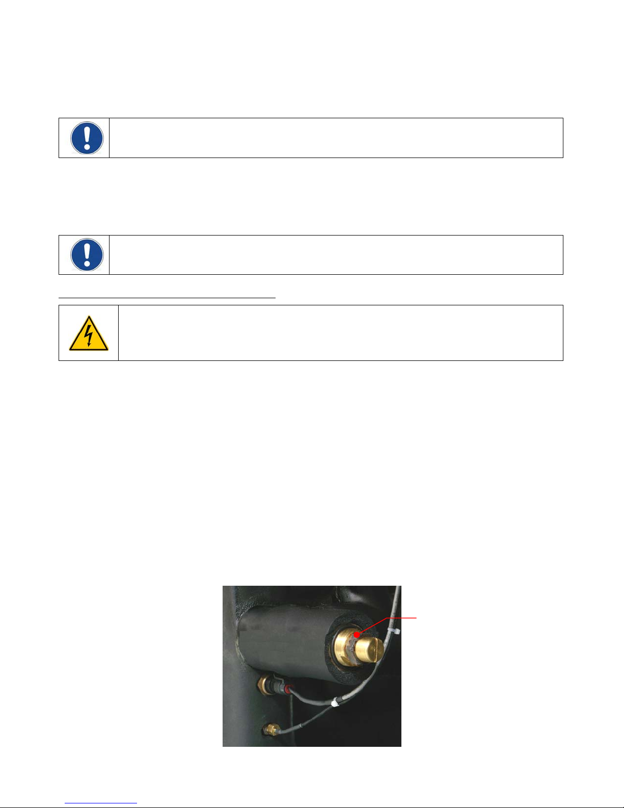
Adjusting the Full Flow Bypass Pressure Setting
WARNING: Hazardous voltages are present.
The pressure setting on the Full Flow Bypass is adjusted as follows:
1. Set the minimum allowable flow rate to 0 (see Normal Operation, Setting Operational Parameters /
Limits, Minimum Flow Rate).
2. Completely block the flow from the Chiller’s fluid outlet. This should cause the pressure to rise.
3. Set the Pressure / Flow Rate Display to read in either PSI or kPa (see Normal Operation, Selecting the
Pressure / Flow Rate Display and Units).
4. Remove the insulation covering the pressure regulating valve cap and then remove the cap. There may
be some coolant in the cap; this is normal.
5. Loosen the locknut and then using a flat blade screwdriver, adjust the pressure until the reading on the
Pressure / Flow Rate Display matches the desired maximum operating pressure. A clockwise rotation
increases pressure; a counter-clockwise rotation decreases pressure.
6. Set the minimum allowable flow rate to the desired value.
7. Tighten the locknut and replace the cap and insulation.
8. Set the Pressure / Flow Rate Display to the preferred reading (GPM, LPM, PSI, kPa).
Locknut
110-279 17
Full Flow Bypass Valve
Page 19
Process Coolant
Suitable Fluids
WARNING: Use only fluids that comply with safety, health, and equipment compatibility requirements. Read
the safety data sheet for the fluid being used carefully before use.
CAUTION: Do not fill the Reservoir with deionized water unless the Chiller is equipped with the DI water
compatible plumbing option.
The Chiller is designed to accommodate a variety of coolant fluids (water, glycol mixtures, etc). For most
applications above 60°F (16°C), distilled water is satisfactory. For operation below 60°F (16°C), the Chiller must
be protected with an antifreeze solution. Laboratory grade ethylene glycol or propylene glycol and water in a
50/50 mixture is satisfactory from 5° to 60°F (-15° to +16°C). Select a fluid that is compatible with the Chiller’s
wetted parts (brass, bronze, stainless steel, EPDM rubber, nylon, PVC).
CAUTION: Coolant freeze protection must be 25°F (14°C) below the lowest possible temperature. The
lowest possible temperature is equal to the process temperature minus the Lower Band ‘Lb’ setting (see
Normal Operation, Setting Operational Parameters / Limits, Lower Band).
WARNING: Do not use caustic, corrosive, or flammable fluids.
CAUTION: Operation below 15°C (59°F) requires antifreeze in the circulation fluid. DO NOT use
automotive antifreeze as the additives may be harmful to the Chiller’s wetted parts.
DO NOT USE the following fluids:
• Automotive antifreeze with additives**
• Hard tap water**
• Deionized water with a specific resistance > 1 meg ohm (except units with the DI water compatible
plumbing
• Any flammable fluids
• Concentrations of acids or bases
• Solutions with halides: chlorides, fluorides, bromides, iodides or sulfur
• Bleach (Sodium Hypochlorite)
• Solutions wi
th chromates or chromium salts
• Glycerin
• Syltherm fluids
** At temperatures above 40°C, additive
allowed to build up, the heater may over
additives can hasten deposit build up.
s or mineral deposits can adhere to the heater. If deposits are
heat and fail. Higher temperatures and higher concentrations of
An algaecide may be added to the coolant fluid to prevent algae growth (see PolyScience Chiller Fluids).
110-279 18
Page 20
Startup
CAUTION: The first time the Chiller is operated it should run for 12 hours in the Standby mode to allow the
compressor crankcase heater to boil off any refrigerant absorbed in the compressor oil.
CAUTION: DO NOT turn Controller power ON until the Reservoir has been filled. When Controller power is
turned ON, the pump automatically begins pumping. If the Reservoir has not been filled, the pump may be
damaged.
Facility Water Flow (water-cooled units only)
1. Open the valves to the facility water supply and return.
2. Check for leaks.
Filling the Reservoir
1. Remove the rear left panel of the Chiller housing. It is held in place with two captive screws.
2. Remove the reservoir cap located on the top of the Reservoir and, using a funnel, add fluid until it is
approximately 2 inches (5.1 cm) below top of reservoir.
3. Once the fluid level is about 2 inches (5.1 cm) below the top of the reservoir, remove the funnel but do not
replace the cap at this time.
110-279 19
Page 21
Starting Process Fluid Flow
1. Place the Power Switch / Disconnect in the ON position. The Control Panel displays will respond by
showing five decimal points (.....). This indicates that the Chiller is in the Standby mode and is ready for
power up. If this is the first time the Chiller is being operated, allow it to run in the Standby mode for 12
hours (see Caution note above).
2. Press the Power Button on the Control Panel. The system startup sequence will begin and proceed as
follows:
• The pump will turn on and fluid will begin circulating through the system.
CAUTION: On initial startup or after long periods of inactivity, run the Chiller for 10 seconds, turn
power OFF, and restart five times to remove any air in the process lines.
• The set point temperature will appear briefly on the Temperature Display; after a few seconds, it will be
replaced by the actual fluid temperature. The right decimal point will flash while the set point is being
displayed.
• The system will go through a short initialization sequence.
• Once initialization has been completed, the compressor will begin operating. When the pressure in the
discharge line reaches 400 psi (27.6 bar), the fan will turn ON. Water-cooled units: The coolant water
regulating valve opens/closes to maintain the pressure in the discharge line at approximately 250 psi
(17.2 bar).
• The Controller will display the actual process fluid temperature and the appropriate ‘degrees’ LED will
be lit (C or F).
3. Check for leaks.
4. With the pump running, the reservoir’s fluid level will drop as the process and/or process cooling lines fill
with fluid. Slowly add fluid to the reservoir until the liquid level remains stable. This means that the system
is filled and any entrained air has been purged.
5. Replace the reservoir cap.
110-279 20
Page 22
Normal Operation
Pressure / Flow Rate Unit
Pressure / Flow
Rate Display
Temperature Unit
Select / Set Knob
Units / Menu
Select Button
Temperature
Display
Power Button
P ower On
When the Power Switch / Disconnect is placed in the ON position, the Controller goes into a “Standby” mode.
Five decimal points (…..) will appear on the Controller’s displays.
CAUTION: DO NOT turn Controller power ON until the Reservoir has been filled. When Controller power is
turned ON, the pump automatically begins pumping. If Reservoir has not been filled, the pump may be
damaged.
Press the Controller’s Power Button. The system startup sequence will begin and proceed as follows:
• The pump will turn on and fluid will begin circulating through the system.
CAUTION: On initial startup or after long periods of inactivity, run the Chiller for 10 seconds, turn
power OFF, and restart five times to remove any air in the process lines.
• The set point temperature will appear briefly on the Temperature Display; after a few seconds, it will be
replaced by the actual fluid temperature. The right decimal point will flash while the set point is being
displayed.
• The system will go through a short initialization sequence.
• Once initialization has been completed, the compressor will begin operating. When the pressure in the
discharge line reaches 400 psi (27.6 bar), the fan will turn ON. Water-cooled units: The coolant water
regulating valve opens/closes to maintain the pressure in the discharge line at approximately 250 psi
(17.2 bar).
• The Controller will display the actual process fluid temperature and the appropriate ‘degrees’ LED will
be lit (C or F).
Temperature Unit (°C or °F) Selection / Factory Default Reset
The LEDs adjacent to the Temperature Display indicate the unit (°C or °F) used for Temperature Displays.
To change from °C to °F or vice versa, proceed as follows:
To change to °F
Units/Menu Select Button while returning the Power Switch / Disconnect to the ON position.
To change to °C
Power Button on the front panel while returning the Power Switch / Disconnect to the ON position.
— Place the Power Switch / Disconnect in the OFF position. Press and hold the
— Place the Power Switch / Disconnect in the OFF position. Press and hold the
IMPORTANT: Temperature set point and many other user-settable operating parameters return to the
original factory defaults when the temperature unit is changed. It is recommended that you record all usersettings before changing the temperature unit or performing a factory default reset so that these operating
parameters can be restored easily to the desired values.
110-279 21
Page 23
A djusting the Set Point Temperature
Press the Select/Set Knob on the front panel. The current set point temperature will be displayed and the
decimal point at the bottom right of the display will flash, indicating the temperature can be changed.
Rotate the Select/Set Knob until the desired set point temperature is displayed. The setting is accepted after the
Select/Set Knob is pressed a second time or automatically after a few seconds of inactivity.
Selecting the Pressure / Flow Rate Display and Units
The Chiller can be set up to display either fluid pressure (in PSI or kPa) or flow rate in GPM or LPM. Pressing
the Units/Menu Select Button briefly toggles through the available selections.
NOTE: The metric pressure reading displayed must be multiplied by 100 for the actual kPa value
NOTE: If there is no flow sensor fitted, the display will show “- -“ when GPM or LPM is selected.
NOTE: The flow rate readout is intended as a reference only. If accurate flow readings are required, an
external flow meter is recommended.
Displaying Internal (P1) and External (P2) Probe Temperatures
The Units/Menu Select Button may also be used to quickly check the internal (P1) and external (P2) probe
temperatures by pressing it once (for P1) or twice (for P2) after the LPM LED is lit. The probe ID will appear on
the Pressure/Flow Rate Display and the probe temperature will appear on the Temperature Display. If an
optional external probe is not installed, the P2 ID will appear but the Temperature Display will show all dashes.
Setting Operational Parameters / Limits
The Chiller’s various operational parameters, such as temperature, flow rate, and pressure alarm values, are all
user-adjustable. They are accessed by pressing and holding the Units/Menu Button until HL appears on the
Pressure/Flow Rate Display. Pressing and releasing the Units/Menu Button once HL appears allows you to
scroll through the various parameters; rotating the Select/Set Knob allows you to change the displayed setting.
You can accept the displayed value by either pressing the Select/Set Knob or allowing the display to timeout.
Operational parameter limit alarms will shut down the compressor, fan, pump and heaters. Some temperature
values are only displayed and settable in ºC. A few parameters require a special keystroke sequence to access
and change values.
NOTE: Some parameters listed may not be included in your version of software.
NOTE: The Ranges and Default Settings shown are for standard models. Ranges and Default Settings for
your unit may differ depending on the options selected.
110-279 22
Page 24

Menu Item Description Choices / Ranges Default Setting
HL High Temperature Limit — Limits the maximum allowable
set point temperature. Audio and visual alarm indicators are
activated when the measured fluid temperature reaches the
HL temperature setting.
NOTE: EHL will appear on the display if the High Limit value
is set below the current set point.
LL Low Temperature Limit — Limits the minimum allowable
set point temperature. Audio and visual alarm indicators are
activated when the measured fluid temperature reaches the
LL temperature setting.
NOTE: ELL will appear on the display if the Low Limit value
is set above the current set point.
HA High Ambient Temperature Limit — Maximum ambient
temperature limit. Displayed and settable only in ºC. Should
the ambient temperature rise above the HA value, the audio
and visual alarms will activate and the compressor, heater,
fan, and pump will turn OFF.
NOTE: The rated cooling capacity on air-cooled chillers is
dependent on an ambient temperature below 104°F (40°C);
performance will decrease as ambient temperature rises.
CAUTION: Continuous operation at ambient temperatures
above 104°F (40ºC) is not recommended for any air-cooled
or water-cooled chiller.
5° to 131°F
(-15° to +55°C)
-4° to 80°F
(-20° to +27°C)
30° to 75ºC
Always displayed
and set in °C
95°F (35°C)
39°F (4°C)
45 ºC
FP Maximum Fluid Pressure — Maximum allowable fluid
pressure; settable in either PSI or kPa. Should the fluid
pressure rise above the maximum fluid pressure value, the
audio and visual alarms will activate and the compressor,
heater, fan, and pump will turn OFF.
NOTE: The Chiller also incorporates a built-in pressure
regulated bypass valve. It will maintain a maximum outlet
pressure by diverting flow of the process fluid to the
reservoir. The bypass valve may be adjusted by the
customer.
CAUTION: Maximum operating pressure for the Chiller is
100 PSI (6.9 bar). Different pumps have different maximum
operating pressures.
FL Minimum Flow Rate — Minimum allowable flow rate;
settable in either GPM or LPM. Should the fluid flow rate
drop below the minimum value, the audio and visual alarms
will activate, and the compressor, heater, fan, and pump will
turn OFF.
Lb Lower Band — This sets how many degrees the process
temperature can fall below set point before the compressor
will turn OFF. It is displayed and settable in °C only.
10 to 100 PSI
0.68 to 6.8 (x100) kPa
Reference:
0.68 = 68 kPa
6.8 = 680 kPa
10 psi = 68.9 kPa
100 psi = 689 kPa
0 to 50 GPM
0 to 190 LPM
1.0° to 5.0°C
Always displayed
and set in °C
100 PSI
6.8 x 100 kPa
(680 kPa)
0 GPM
0 LPM
2.0°C
110-279 23
Page 25

Menu Item Description Choices / Ranges Default Setting
Ub Upper Band — This sets how many degrees the process
temperature can rise above set point before the compressor
will turn ON. It is displayed and settable in °C only.
C1
C2
C3
Calibration Offset — Allows the Chiller’s displayed and
control or externally sensed temperature to match an
independent traceable standard. The Calibration Offset is
displayed and settable in °C only.
C1 — Internal calibration offset
C2 — External calibration offset
C3 — External calibration offset
NOTE: A special keystroke sequence is required to adjust the
Calibration Offset. See Calibration Offset.
Cd Compressor Delay — Allows the operator to set the minimum
amount of time allowed from when the Compressor turns OFF
to when it turns back ON again.
NOTE: When the Compressor turns OFF because it has
reached the Lb value, it will remain OFF until both the Ub (°C)
value has been reached and the Cd (delay time) value has
expired.
Fc Flow Rate Calibration — Allows adjustment of the displayed
flow rate to match that of a known standard.
NOTE: During Flow Rate Calibration, the left hand LCD
displays the desired flow rate in GPM. The right hand LCD
displays the Gain value.
NOTE: A special keystroke sequence is required to adjust the
Flow Rate Calibration. See Flow Rate Calibration.
1.0° to 5.0°C
2.0°C
Always displayed
and set in °C
±2.9°C
0.0°C
Always displayed
and set in °C
10 to 300 seconds 20 seconds
Varies
Record current
Gain value for
reference
dS Coolant Density — This value is set at the factory and
should not be changed.
Sh Specific Heat — This value is set at the factory and should
not be changed.
CC Current Control (optional) – Allows setting of the set point
temperature via a 4-20 mA analog signal.
YES = Enables current control
NO = Disables current control
PC Communications Baud Rate — Selects the baud rate for
serial (RS-232/RS-485) communication.
LA Low Ambient Temperature Limit —Minimum ambient
temperature limit. Displayed and settable only in ºC. Should
the ambient temperature fall below the LA value, the audio
and visual alarms will activate and the compressor, heater,
fan, and pump will turn OFF.
110-279 24
0.1 to 9.00 8.35
0.1 to 1.00 1.00
Yes or No No
24 (2400), 48 (4800),
96 (9600) or 192 (19200)
1 to 7°C
Always displayed
and set in °C
lb/gal
BTU/lb °F
9600
2°C
Page 26

Menu Item Description Choices / Ranges Default Setting
Pd Password — For factory use only.
td HGB Valve Delay — For factory use only.
Fb
Fuse Bits — The current Fuse Bits (Fb) setting appears after the td setting and can be viewed, but not
changed. To change Fuse Bits (Fb) operational parameters, electrical power must be turned OFF and a
special key stroke combination entered. See Fuse Bits (Fb) for detailed instructions.
Input Logic State h00 h01 h02 h04 h05 h06
Remote
On / Off
dry contact
Remote
24 VDC
On / Off
Water Level
Float Switch
Closed OFF ON OFF ON
Open ON OFF
24 VDC OFF ON OFF ON
0 VDC ON
Open OK OK OK Low Low Low
N/A
0 to 999 0
0 to 999 2
N/A
ON OFF
OFF ON
N/A
N/A
OFF
Closed Low Low Low OK OK OK
You can adjust the following settings for your particular application or simply accept the default values.
High Temperature Limit (HL)
This menu item serves two functions. First, it establishes the maximum allowable set point temperature and thus
helps prevent an operator from inadvertently selecting a temperature set point above a pre-established value.
Secondly, it serves as a high temperature alarm, automatically activating both audio and visual alarm indicators
if the measured fluid temperature reaches the HL setting. This also causes the compressor, heater, fan, and
pump to turn OFF.
To change the high limit value, rotate the Select/Set Knob until the desired value is displayed.
HL
95
Low Temperature Limit (LL)
This menu item also serves a dual function. First, it establishes the minimum allowable set point temperature
and thus helps prevent an operator from inadvertently selecting a temperature set point below a pre-established
value. Secondly, it serves as a low temperature alarm, automatically activating both audio and visual alarm
indicators if the measured fluid temperature drops to the LL setting. This also causes the compressor, heater,
fan, and pump to turn OFF.
To change the low limit value, rotate the Select/Set Knob until the desired value is displayed.
LL
110-279 25
39
Page 27

High Ambient Temperature Limit (HA)
NOTE: This value is always set in °C.
This menu item protects the Chiller from overheating due to a high ambient temperature. Should the ambient
temperature rise above the limit value, the audio and visual alarms will activate and the compressor, heater, fan,
and pump will turn OFF.
To change the high ambient temperature value, rotate the Select/Set Knob until the desired value is displayed
on the Temperature Readout.
HA
45
Maximum Fluid Pressure (FP)
This is the maximum allowable fluid pressure and can be set in either PSI or kPa (the LED adjacent to the
display indicates the active unit of measure). Should the fluid pressure rise above the maximum fluid pressure
value, the audio and visual alarms will activate and the compressor, heater, fan, and pump will turn OFF.
To change the fluid pressure limit value, rotate the Select/Set Knob until the desired value is displayed on the
Temperature Readout.
NOTE: When FP first appears, the PSI LED will be lit. To view the FP value in kPa, press the Units/Menu
Button again. FP will remain on the display and the kPa LED will light up.
PSI
FP
FP
NOTE: The Chiller incorporates a built-in safety that automatically maintains fluid pressure below a valve-
regulated pressure value. It maintains this maximum outlet pressure by diverting the flow of process fluid to
the Reservoir (i.e., begin internally recirculating the fluid). A maximum pressure value is set at the factory,
but is user-adjustable. See “Installation and Startup, External Piping, Full Flow Bypass” for information on
changing the maximum outlet pressure value.
kPa x 100
100
6.8
Minimum Flow Rate (FL)
This is the minimum allowable flow rate and can be set in either GPM or LPM (the LED adjacent to the display
indicates the active unit of measure). Should the fluid flow rate drop below the minimum value, the audio and
visual alarms will activate, and the compressor, heater, fan, and pump will turn OFF.
To change the minimum flow rate value, rotate the Select/Set Knob until the desired flow rate value is displayed
on the Temperature Readout.
With FL set to “0”, the flow alarm is disabled, and the Chiller will continue to operate with the output flow
blocked.
NOTE: When FL first appears, the GPM LED will be lit, indicating the FL value is GPM. To view the FL
value in LPM, press the Units/Menu Button again. FL will remain on the display and the LPM LED will light
up.
FL
110-279 26
GPM
●
1.5
Page 28

LPM
●
FL
06
Lower Band (Lb)
NOTE: This value is always displayed/set in °C.
This menu item allows you to set how many degrees the process temperature can fall below set point before the
Compressor will turn OFF.
To change the lower band value, rotate the Select/Set Knob until the desired value is displayed.
Lb
2.0
Upper Band (Ub)
NOTE: This value is always displayed/set in °C.
This menu item allows you to set how many degrees the process temperature can rise above set point before
the Compressor will turn ON.
To change the upper band value, rotate the Select/Set Knob until the desired value is displayed.
Ub
2.0
Calibration Offset (C1 / C2 / C3)
IMPORTANT: To prevent the operator from accidentally changing the calibration offset, a special
keystroke sequence is required to access this function.
This menu item allows you to adjust the Chiller’s internal and/or external temperature reading to match that of a
traceable standard. It allows you to offset the displayed temperature value by as much as ±2.9°C.
NOTE: Calibration offset values are always set and displayed in °C.
1. Press and hold the Units/Menu Button until HL appears on the display.
2. Press and release the Units/Menu Button until the operating parameter preceding the calibration value you
wish to change appears on the display.
For C1 (Internal Calibration Offset), the preceding operating parameter is Ub
For C2 (External Calibration Offset), the preceding operating parameter is C1
For C3 (External Calibration Offset), the preceding operating parameter is C2
3. Press and hold
the Units/Menu Button.
4. While holding the Units/Menu Button, press and release the Select/Set Knob.
5. When CAL will appears on the Temperature Display, release the Unit/Menu Button. The current calibration
offset value will appear on the Temperature Display and alternate with the fluid temperature reading
(enabling you to simultaneously adjust the offset and see the effect on the temperature).
6. Rotate the Select/Set Knob until the desired calibration offset is displayed. Press the Select/Set Knob
or simply allow the display to time out to accept the displayed value.
110-279 27
Page 29

C1
Compressor Delay (Cd)
This menu item allows you to adjust the minimum amount of time (in seconds) the Compressor should be OFF
before it cycles back ON.
To change the compressor delay, rotate the Select/Set Knob until the desired value is displayed.
Cd
Flow Rate Calibration (Fc)
NOTE: Your Chiller’s flow rate is calibrated at the factory at the nominal flow value for the installed pump.
Further adjustment is not necessary.
0.0
20
This menu item allows you to adjust the flow rate display to match that of a known standard.
1. Press and hold
2. Press and release the Units/Menu Button until Cd appears on the display.
3. Press and hold
4. While holding the Units/Menu Button, press and release the Select/Set Knob.
5. When CAL appears on the Temperature Readout, release the Units/Menu Button.
6. Rotate the Select/Set Knob until the desired offset is displayed. Press the Select/Set Knob or simply allow
the display to time out to accept the displayed value.
the Units/Menu Button until HL appears on the display.
the Units/Menu Button.
Fc
0.0
Coolant Density (dS)
This menu item is for factory use only and should not be changed.
Specific Heat (Sh)
This menu item is for factory use only and should not be changed.
dS
Sh
8.35
1.00
Current Control (CC)
This optional menu item allows you to adjust the temperature set point using a 4-20 mA analog signal. To
change the displayed setting, rotate the Select/Set Knob until the desired selection is displayed (YES = enabled;
NO = disabled).
CC
110-279 28
NO
Page 30

Communications
This menu item allows you to establish the baud rate for serial communication. Allowable settings are 0 (no
serial communication), 24 (2400 baud), 48 (4800 baud), 96 (9600 baud), 192 (19200 baud).
To change the displayed setting, rotate the Select/Set Knob until the desired baud rate is displayed.
Press the Select/Set Knob or allow the display to time out to accept the displayed value.
Low Ambient Temperature Limit (LA)
Baud Rate (PC)
PC
NOTE: This value is always set in °C.
96
This menu item sets the lowest allowable ambient temperature at which the Chiller should operate. Should the
ambient temperature fall below the limit value, the audio and visual alarms will activate and the compressor,
heater, fan, and pump will turn OFF.
To change the low ambient temperature value, rotate the Select/Set Knob until the desired value is displayed on
the Temperature Readout.
LA
Password (Pd)
This menu item is for factory use only and is not operator adjustable.
Pd
HGB Valve Delay (td)
This menu item is for factory use only and is not operator adjustable.
Fuse Bits (Fb)
This menu item allows you to select the logic settings for remote control and the water level float switch. To set
fuse bits, proceed as follows:
1. Place the Power Switch / Disconnect in the OFF position.
2. Press and hold the Select/Set Knob and Power Button simultaneously.
3. While holding the Select/Set Knob and Power Button, place the Power Switch / Disconnect in the ON
position.
4. Fb will appear on the Pressure/Flow Rate Display; h followed by two digits will appear on the Temperature
Display.
5. Rotate the Select/Set Knob to the desired setting (h00, h01, h02, h04, h05, or h06).
6. Press and release the Select/Set Knob or simply allow the display to time out to accept the displayed
setting.
td
Fb
2
0
2
h00
110-279 29
Page 31

Enabling / Disabling the Local Lockout
This feature is used to prevent unauthorized or accidental changes to set point and other operational values.
When enabled, the values for set point and operational parameters can be displayed, but not changed:
To enable the local lockout, press and hold the Select/Set Knob until LLO is displayed (approximately 5
seconds). Once enabled, LLO will appear momentarily when the Select/Set Knob is pressed to display the set
point.
To disable the local lockout, press and hold the Select/Set Knob until CAn appears momentarily as local lockout
status changes from enabled (LLO) to disabled (approximately 5 seconds).
IMPORTANT: The Local Lockout feature does not prevent set point changes entered via the RS-232
interface.
110-279 30
Page 32
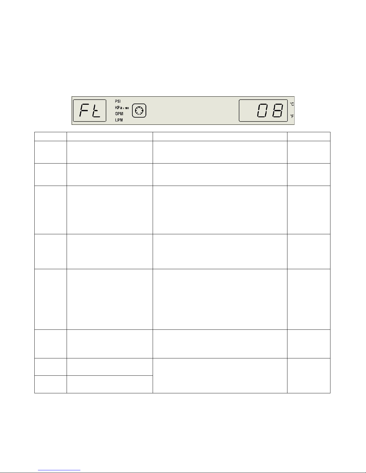
Display, Alarm and Error Messages
When an alarm or error condition is detected, Ft appears on the Pressure/Flow Rate Display and a
corresponding code flashes on the Temperature Display. Operational limit parameter alarms will shut down the
compressor, fan, pump, and heaters. Alphabetical codes will also appear on the Temperature Display. An audio
alarm will also sound.
After taking corrective action, restart the Chiller to clear the fault or error.
Code Description Action Required Default
Alarm – Process fluid temperature has dropped
02
03
04
05
07
08
09
10
Low limit temperature alarm
High limit temperature alarm
Over-temperature alarm
(select models only)
Low liquid level alarm
(units with Liquid Level Float
Switch option only)
Low flow alarm
High pressure alarm
Internal software fault
Triac fault
below the low limit temperature setting.
Increase heat load or decrease LL setting.
Alarm – Process fluid temperature has reached the
high limit temperature setting.
Decrease heat load or increase HL setting.
Alarm – Process fluid temperature is above the
factory set high temperature cutout.
Air-cooled units: Cutout will reset automatically after
the temperature of the fluid is lowered.
Water-cooled units: Reset cutout manually by
pressing red button on rear of unit after the
temperature of the fluid is lowered.
Delayed Alarm – Activated when the liquid level in the
Reservoir falls below an acceptable level for 30
seconds.
Wired in series with mechanical flow switch; see 07
low flow alarm.
Alarm – Flow rate has dropped below minimum flow
rate setting.
Correct low flow condition or decrease FL setting.
Secondary: Mechanical flow switch closes with flow
(~4 gpm / 15 lpm minimum). If installed in
combination with optional liquid level float switch,
they are wired in series and both must be closed. If
either is open due to low flow or low liquid level, this
alarm or EFL will be activated. See EFL.
Delayed Alarm – Activated when the fluid outlet
pressure has exceeded the high pressure limit setting
for 30 seconds.
Decrease outlet pressure or increase FP setting.
Fault – Default unit to °C or °F. If fault persists,
replace Control PCB.
Note: Some parameters will reset to default values;
this could activate another fault code. Review and
return all parameters to user settings.
39°F (4°C)
95°F (35°C)
Units without
heater option
“OPT”
jumpered on
PCB
See Fuse Bit
settings
~4 gpm
(15 lpm)
minimum
required for
flow switch
100 psi
(689 kPa)
N/A
110-279 31
Page 33

Code Description Action Required Default
11
12
13
14
15
16
17
18
19
20
21
22
EFL
EHA
EHL
Internal RTD probe fault
External RTD probe fault
Communications fault
Fault – RTD sensor failure.
Check for open or shorted sensor (reference
resistance value: 100 ohms @ 0°C / 138.5 ohms @
100°C. If probe tests good, replace Control PCB.
Fault – Default unit to °C or °F. If fault persists,
N/A
replace Control PCB.
ADC fault, internal probe
ADC fault, external probe
High ambient temperature alarm,
front panel
(select models only)
High ambient temperature alarm,
rear panel
(select models only)
Ambient temperature probe fault
(P3)
(select models only)
Note: Some parameters will reset to default values;
this could activate another fault code. Review and
return all parameters to user settings.
Alarm – Maximum ambient temperature limit has
been exceeded.
Note: The cooling capacity of air-cooled units is
dependent on an ambient temperature below 104°F
(40°C); performance will decrease as ambient
temperature increases.
Continuous operation at ambient temperatures above
104°f (40°C) is not recommended for any air-cooled
or water-cooled Chiller.
Fault – RTD sensor failure.
Check for open or shorted sensor (reference
resistance value: 100 ohms @ 0°C / 138.5 ohms @
100°C. If probe tests good, replace Control PCB.
N/A
45°C
N/A
Pump – Check continuity across DAP1 on PCB
Pump overload (DAP1) fault
through NO contacts on overload relay; reset
N/A
overload relay; check pump fuses.
Compressor overload (DAF2) Compressor pressure sensors. See Troubleshooting. N/A
Fan(s) – Check continuity across DAF1 on PCB
through NO contacts on overload relay; check fan(s)
Fan overload (DAF1) fault
fuses.
N/A
Note: On 10 HP Chillers, both overload relays NO
contacts are wired in series with DAF1.
Pump 2 overload (DAP2) fault
(select models only)
Pump 2 option only – Check continuity through NO
contacts on overload relay; reset overload relay;
check pump fuses.
DAP2
jumpered on
PCB
Warning / Alarm – Fluid level or float switch is open.
Low liquid level or low fluid flow
Alarm will sound once every 8 seconds for 5
occurrences. If problem has not been corrected after
N/A
40 seconds, Fault 05 occurs.
Alarm – The ambient temperature (as measured on
the Control PCB) is higher than the high ambient
temperature setting. If ambient temperature stays
High ambient temperature alarm
over 5°C above the HA setting, Fault 16 or 17 is
45°C
activated.
Lower ambient temperature or increase the HA
setting.
Alarm – The temperature set point is higher than the
high limit temperature setting. The display alternates
High limit temperature alarm
between EHL and the fluid temperature. The unit
continues normal operation. If the fluid temperature
95°F (35°C)
rises above the HL setting, Fault 03 is activated.
Decrease heat load or increase the HL setting.
110-279 32
Page 34
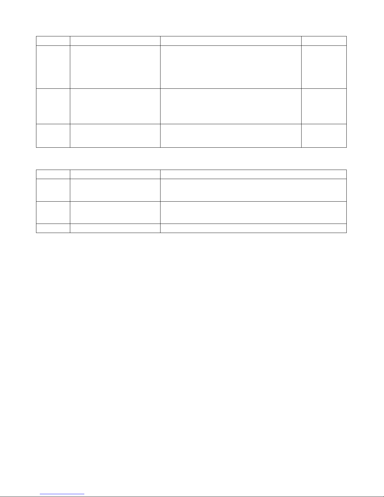
Code Description Action Required Default
Alarm – The temperature set point is lower than the
low limit temperature setting. The display alternates
ELL
LO H2O
ECC
Low limit temperature alarm
No fluid flow or pressure
Error current control
between ELL and the fluid temperature. The unit
continues normal operation. If the fluid temperature
drops below the LL setting, Fault 02 is activated.
Increase heat load or decrease the LL setting.
Warning – LO is displayed alternately with H2O and
the fluid temperature. Indicates that the fluid pressure
exceeds the high pressure limit or the fluid flow is
less than the low flow limit. If either error persists,
Fault 07 or 08 will be activated.
Alarm – The current input is outside 4-20 mA. Pump,
compressor, and fan turn OFF.
Send in-range 4-20 mA input to restart Chiller.
39°F (4°C)
N/A
N/A
The following Codes indicate display control status.
Code Description Action Required
Normal – Indicates that the Local Lockout feature is enabled. Appears
LLO
CAn
EC
Local lockout
Cancel local lockout
External remote control active Normal – Chiller is in Standby mode until remotely activated (optional)
momentarily when the Select/Set Knob is pressed to view/change set
point value. See Enabling/Disabling the Local Lockout.
Normal – Indicates that the Local Lockout feature has been disabled.
Appears momentarily when Local Lockout status is changed from
enabled (LLO) to disabled. See Enabling/Disabling the Local Lockout.
Automatic Restart from Alarm Mode
The Chiller is equipped with an automatic restart feature to avoid false or nuisance alarms due to temporary flow
obstructions, temperature swings, or electrical line noise. If any alarm condition is detected, the Chiller will turn
OFF, wait 30 seconds, and turn back ON automatically. If the alarm condition persists after three restart
attempts are made, then an alarm will sound and the Chiller will remain OFF until the problem is corrected.
110-279 33
Page 35
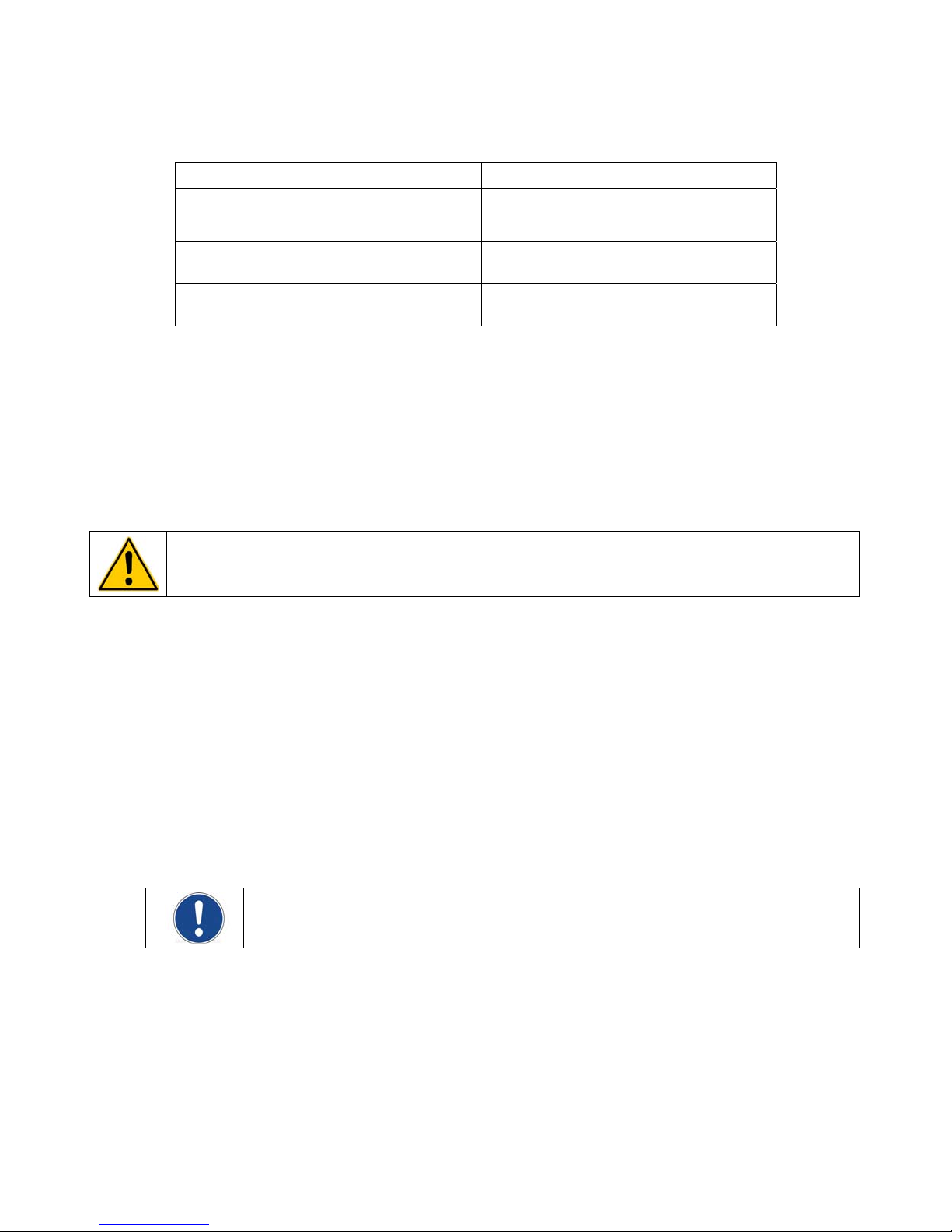
Routine Maintenance
Recommended Routine Maintenance Schedule
Routine Maintenance Procedure Frequency1
Check reservoir coolant level Monthly
Check coolant freeze protection Monthly
Inspect and clean inline strainer Weekly for first month of operation;
every 3 months thereafter.
Inspect and clean air filters Weekly for first month of operation;
every 3 months thereafter.
1. Minimum maintenance frequency. Your plant conditions may require more frequent inspection and
cleaning.
Reservoir Coolant Level
The coolant level in the Reservoir should be checked on a monthly basis and replenished as required. A proper
fill level is approximately 2 inches (5.1 cm) below the top of the Reservoir. If fluid replacement is required, slowly
add coolant until the proper fill level is achieved. You may add coolant either directly to the Reservoir or through
the top of the Liquid Level Sight Glass on the rear of the unit.
Coolant Freeze Protection
CAUTION: Coolant freeze protection must be 25°F (14°C) below the lowest possible temperature. The
lowest possible temperature is equal to the process temperature minus the Lower Band (Lb) setting. See
Normal Operation, Setting Operational Parameters / Limits.
If your Chiller is operating below 59°F (15°C), it must be protected with an antifreeze solution. The coolant
should be checked periodically for proper freeze protection.
Inline Strainer
The Chiller’s inline strainer should be inspected and cleaned weekly for the first month of operation. Once you
are certain that all debris that has been generated or dislodged has been removed from the process coolant,
strainer inspection and cleaning should be performed every three months or as required, whichever is more
frequent.
1. Place the Power Switch / Disconnect in the OFF position.
2. Remove the Chiller’s left side rear panel. The inline strainer is located just above the Reservoir at the
inlet to the Chiller.
3. Using an adjustable wrench or the proper size hex head socket, loosen and remove the inline strainer
cap and screen.
NOTE: There will be a small amount of residual coolant within the housing of the inline strainer
which will drain out when the cap is removed.
4. Clean the screen. Either water or high pressure air can be used to remove accumulated debris.
5. Replace screen and drain cap and tighten.
6. Place Power Switch / Disconnect in the ON position.
7. Check for leaks before replacing left rear side panel.
110-279 34
Page 36

Air Filters
Chillers incorporate two or more high-efficiency, removable air filters. These should be inspected weekly during
the first month of operation to determine how frequently cleaning is required. Units located in dusty or oily
environments will require more frequent air filter cleaning.
CAUTION: DO NOT allow the air filters to become caked with dust or coated with an oily film. This
significantly reduces air flow and will decrease cooling efficiency. It can also lead to filter breakthrough,
allowing dust and oil to get into and on the fins and coils of the condenser.
The Chiller’s air filters are removed and cleaned as follows:
1. Grasp the strap at the bottom center of the air filter and gently lift up and away from the Chiller housing.
2. Direct water or a high pressure air stream through the back of the filter (downstream side) opposite the
air flow arrow. If using water, allow the filter to dry before reinstalling.
3. Position the top edge in the upper channel of the Chiller housing, with the air flow arrow pointing toward
the inside of the Chiller housing.
4. Gently lift on the bottom strap and push the bottom edge of the filter toward the housing until the filter is
securely in place.
110-279 35
Page 37
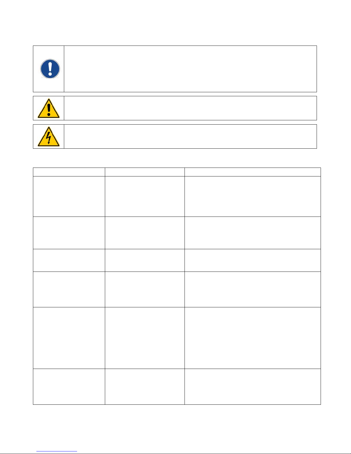
Troubleshooting
NOTE: Many problems can be resolved by restoring the factory defaults. If this solves the problem, be
careful when restoring your operational settings in order not to repeat the problem.
To restore the factory default settings:
1. Place the Power Switch / Disconnect in the OFF position.
2. Press and hold the Units/Menu Button (for °F) or the Power Button (for °C) while returning the
Power Switch / Disconnect to the ON position.
WARNING: Service should only be performed by qualified personnel. Extreme caution is required as
hazards are present when servicing this equipment.
WARNING: When electrical power is ON, dangerous voltages exist within chassis components. Use
extreme care when measuring voltages on live circuits.
Troubleshooting Chart
Problem Possible Causes Corrective Action
Unit does not run
(digital displays blank)
Unit does not run
(three decimal points appear
on Temperature Display,
two decimal points on
Pressure/Flow Rate Display)
No fluid circulation Insufficient fluid in reservoir
Insufficient circulation Fluid viscosity too high
Unit does not cool or cooling
is insufficient
Fault code 20 on display Refrigerant pressure too high
No power to unit
Unit in Standby mode Press Power Button on front panel.
Blockage in circulating system
Pump is not operating
External tubing diameter too
small
Restrictions in fluid lines
Low or high line voltage
Dust build up on air filter or
condenser
Blocked air ventilation screens
Facility water too warm
Excessive heat load
Ambient air temperature too
high
Low or high line voltage
Refrigerant pressure too low
Faulty refrigerant pressure
sensor
Check that the electrical wiring is secure and connected
to an operating electrical source.
Check that Power Switch / Disconnect is in the ON
position.
Check the phase monitor indicator light for correct phase
wiring.
Add fluid to reservoir.
Remove blockage.
Replace pump.
Replace with lower viscosity fluid.
Replace with larger diameter tubing.
Check and correct as required.
Check and correct as required.
Clean air filter and/or condenser as required.
Remove blockages as required.
Check and correct as required.
Check that heat load does not exceed capacity of
Chiller; correct as required.
Decrease ambient air temperature.
Check and correct as required.
See Compressor Overload Fault, below.
110-279 36
Page 38

Compressor Overload Fault (Ft 20)
The Chiller has both low and high refrigerant pressure sensors. They are wired in series and connect to DAF2
on the Control PCB. If either sensor opens, the Ft 20 alarm is activated. To troubleshoot, measure the continuity
across each senor.
Low Pressure Sensor
The low pressure sensor opens if the suction pressure drops below 15 psi (1 bar) and automatically closes
when the suction pressure rises above 30 psi (2.1) bar. If a continuity check of this sensor shows that it is open,
it is probably due to a loss of refrigerant, although a faulty sensor cannot be ruled out. Contact your local HVAC
technician to check the refrigeration system.
High Pressure Sensor
The high pressure sensor opens if the discharge pressure exceeds 630 psi (43.4 bar). If a continuity check
shows that this sensor is open, it may be due to high ambient temperature, dirty air filters, or large heat loads. A
faulty sensor cannot be ruled out.
Once the high pressure sensor opens, it must be manually reset as follows:
WARNING: Compressor and copper tubing may be very hot.
1. Remove the front right side panel of the Chiller housing.
2. Locate the blue sensor with red reset button on the compressor discharge line.
3. Depress the red reset button.
4. Replace front right side panel.
If high ambient temperature, dirty air filters, or large heat loads have been ruled out as reasons for an open high
pressure sensor and the sensor remains open or continues to open, contact your local HVAC technician to
check the refrigeration system.
110-279 37
Page 39
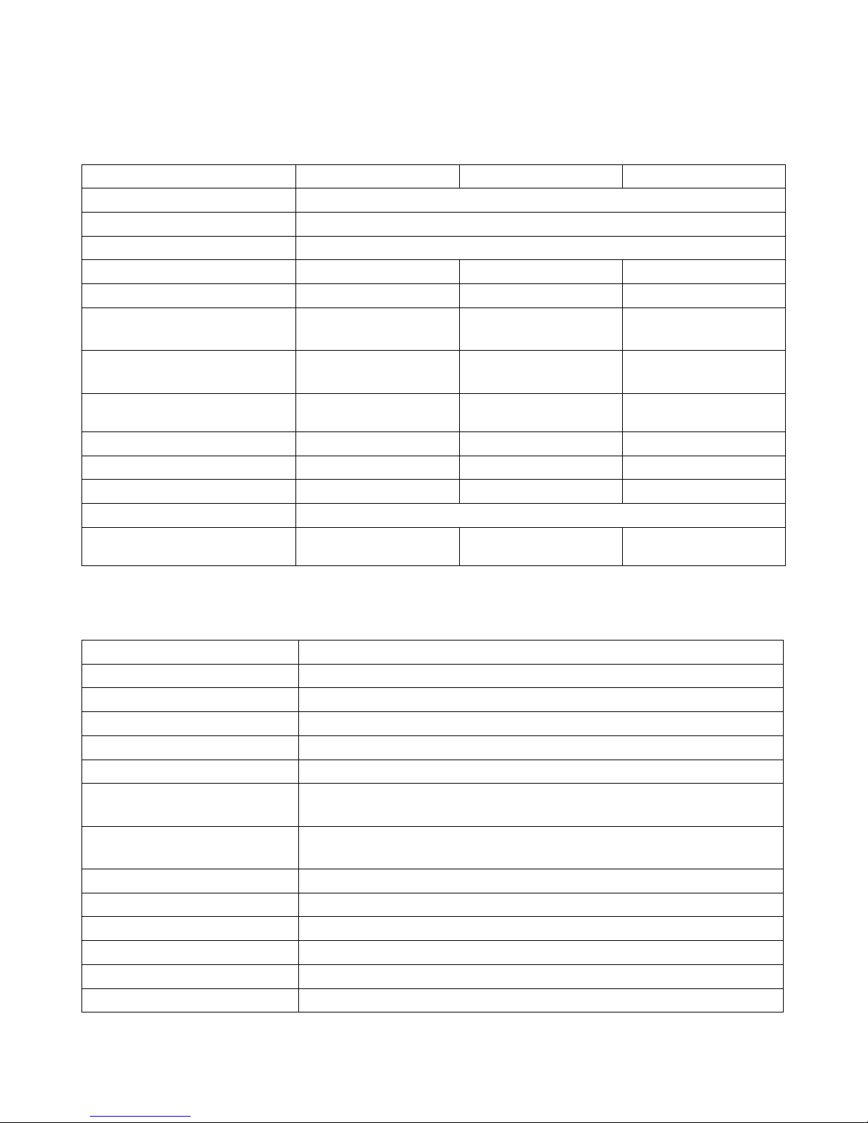
Technical Information
Chiller Specifications
Air-Cooled Chillers (DA500, DA750, DA1000)
Model DA500 DA750 DA1000
Process temperature range 32° to 86°F (0° to 30°C)
Temperature stability ±2.0°F (±1.11°C)
Ambient operating temperature 60° to 104°F (16° to 40°C)
Copeland Scroll compressor 5 HP 7.5 HP 10 HP
Refrigerant charge (R-410A) 8 lbs. (3.6 kg) 12 lbs. (5.4 kg) 16 lbs. (7.3 kg)
Cooling capacity1
60 Hz models
Cooling capacity1
50 Hz models
Nominal evaporator flow2 11.7 USGPM
Fan 1 HP 1 HP 1 HP x 2
Condenser discharge air flow 6000 CFM 6000 CFM 6000 CFM
Reservoir tank capacity 16 gallons (60.5 liters) 16 gallons (60.5 liters) 45 gallons (170 liters)
Process water connections 1.5 inch FPT
Dimensions (L x W x H) 56 x 34.5 x 67 in.
1. Capacity based on 68°F (20°C) entering air and 68°F (20°C) leaving water.
2. Chiller flow rate based on 2.4 USGPM/ton (0.54 m
16,384 watts
55,869 BTU
14,418 watts
50,515 BTU
(44.3 lpm)
142.2 x 88 x 170.2 cm
3
/hr/ton)
22,361 watts
76,251 BTU
19,678 watts
67,102 BTU
15.7 USGPM
(59.4 lpm)
56 x 34.5 x 67 in.
142.2 x 88 x 170.2 cm
195.6 x 88 x 173.2 cm
33,436 watts
114,016 BTU
29,424 watts
100,336 BTU
23.8 USGPM
(90.1 lpm)
77 x 34.5 x 68.2 in.
Water-Cooled Chiller (DW500)
Model DW500
Process temperature range 32° to 86°F (0° to 30°C)
Temperature stability ±2.0°F (±1.11°C)
Ambient operating temperature 60° to 104°F (16° to 40°C)
Copeland Scroll compressor 5 HP
Refrigerant charge (R-410A) 8 lbs. (3.6 kg)
Cooling capacity
60 Hz models
Cooling capacity
50 Hz models
Nominal evaporator flow1 12.7 USGPM (48.1 lpm)
Condenser water flow2 15.4 USGPM (58.1 lpm)
Reservoir tank capacity 16 gallons (60.5 liters)
Process water connections 1.5 inch FPT
Facility water connections 0.75 inch FPT
Dimensions (L x W x H) 56 x 34.5 x 32.1 inches / 142.3 x 88 x 81.6 cm
1. Chiller flow rate based on 2.4 USGPM/ton (0.54 m3/hr/ton)
2. Tower flow rate based on 85°F (29°C) entering water and 95°F (35°C) leaving water.
Specifications subject to change without notice.
17,825 watts
60,840 BTU
14,850 watts
50,715 BTU
110-279 38
Page 40
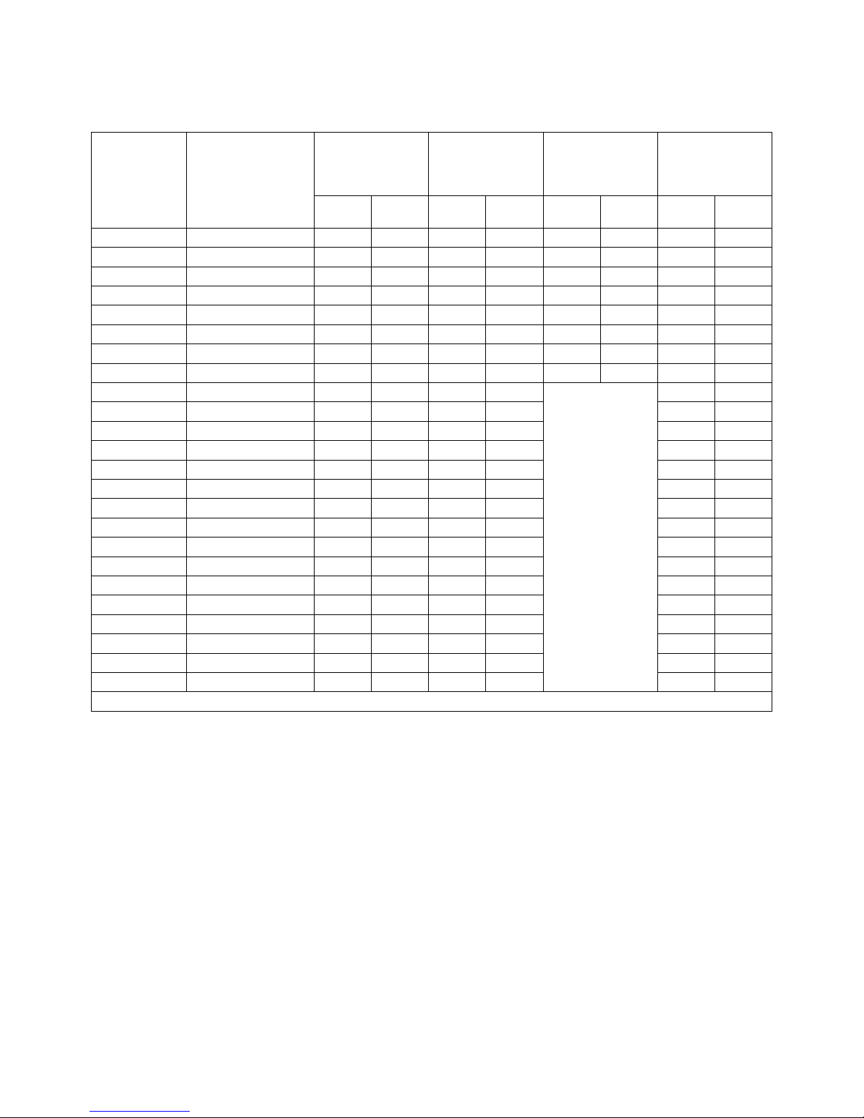
Electrical Specifications
DA500 Chillers
Max. Operating
Current / Fuse –
Circuit Breaker Size
with 9000 Watt Heater
Option
Max.
Amps
Fuse –
CB Size
Model
Voltage / Phase /
Hertz
Max. Operating
Current / Fuse –
Circuit Breaker Size
with no heaters
Max.
Amps
Fuse –
CB Size
Max. Operating
Current / Fuse –
Circuit Breaker Size
with 3000 Watt Heater
Option
Max.
Amps
Fuse –
CB Size
Max. Operating
Current / Fuse –
Circuit Breaker Size
with 7500 Watt Heater
Option
Max.
Amps
Fuse –
CB Size
DA504F 208-230V / 3 / 50-60 29.4 45 36.6 55 47.4 70 51.1 75
DA504G 208-230V / 3 / 50-60 32.6 50 39.8 60 50.6 75 54.3 80
DA504C3 208-230V / 3 / 50-60 35.1 55 42.3 65 53.1 80 56.8 80
DA504C5 208-230V / 3 / 50-60 39.7 60 46.9 75 57.7 85 61.4 85
DA504D1/S1 208-230V / 3 / 50-60 31.4 50 38.6 60 49.4 75 53.1 80
DA504D2/S2 208-230V / 3 / 50-60 35 55 42.2 65 53 80 56.7 80
DA504D3/S3 208-230V / 3 / 50-60 39 60 46.2 70 57 85 60.7 85
DA504D6/S6 208-230V / 3 / 50-60 32.6 50 39.8 60 50.6 75 54.3 80
DA506F 380V / 3 / 50 15.2 25 18.8 30 26 40
DA506G 380V / 3 / 50 16.7 25 20.3 30 27.5 40
DA506C3 380V / 3 / 50 17.2 25 20.8 30 28 40
DA506C5 380V / 3 / 50 18.3 30 21.9 35 29.1 45
DA506D1/S1 380V / 3 / 50 16.2 25 19.8 30 27 40
DA506D2/S2 380V / 3 / 50 18.1 30 21.7 35 28.9 45
DA506D3/S3 380V / 3 / 50 19.6 30 23.2 35 30.4 45
DA506D6/S6 380V / 3 / 50 16.8 25 20.4 30 27.6 40
DA508F 460V / 3/ 60 15.4 25 19 30 26.2 40
NA
DA508G 460V / 3/ 60 16.9 25 20.5 30 27.7 40
DA508C3 460V / 3/ 60 18 30 21.6 35 28.8 45
DA508C5 460V / 3/ 60 20 30 23.6 35 30.8 45
DA508D1/S1 460V / 3/ 60 16.2 25 19.8 30 27 40
DA508D2/S2 460V / 3/ 60 17.5 25 21.1 35 28.3 40
DA508D3/S3 460V / 3/ 60 20.2 30 23.8 35 31 45
DA508D6/S6 460V / 3/ 60 16.4 25 20 30
27.2 40
For 575 Volt units consult the factory
110-279 39
Page 41
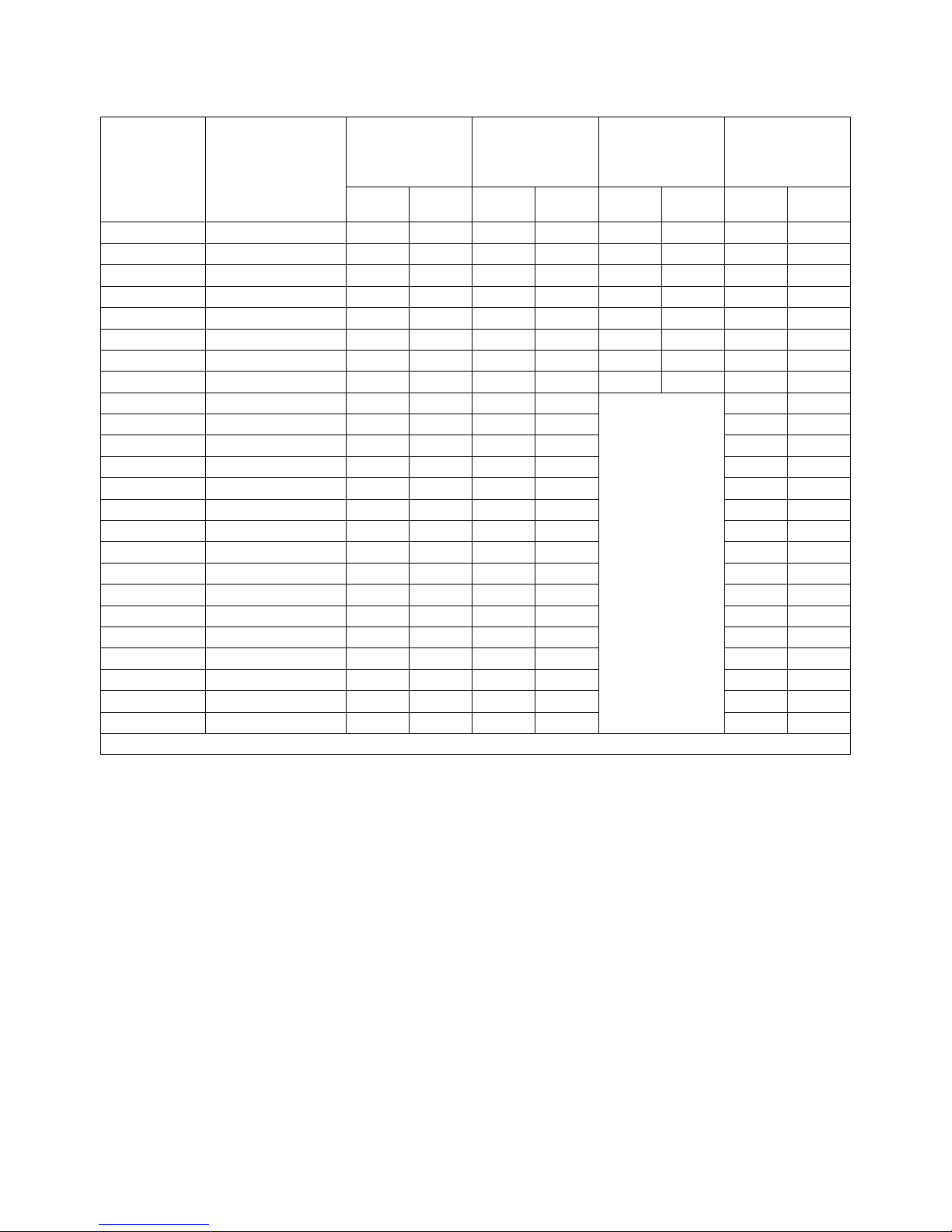
DW500 Chillers
Max. Operating
Current / Fuse –
Circuit Breaker Size
with 9000 Watt Heater
Option
Max.
Amps
Fuse –
CB Size
Model
Voltage / Phase /
Hertz
Max. Operating
Current / Fuse –
Circuit Breaker Size
with no heaters
Max.
Amps
Fuse –
CB Size
Max. Operating
Current / Fuse –
Circuit Breaker Size
with 3000 Watt Heater
Option
Max.
Amps
Fuse –
CB Size
Max. Operating
Current / Fuse –
Circuit Breaker Size
with 7500 Watt Heater
Option
Max.
Amps
Fuse –
CB Size
DW504F 208-230V / 3 / 50-60 25.4 40 32.6 50 43.4 70 47.1 70
DW504G 208-230V / 3 / 50-60 28.6 45 35.8 55 46.6 70 50.3 75
DW504C3 208-230V / 3 / 50-60 31.1 50 38.3 60 49.1 75 52.8 80
DW504C5 208-230V / 3 / 50-60 35.7 55 42.9 65 53.7 80 57.4 80
DW504D1/S1 208-230V / 3 / 50-60 27.4 45 34.6 55 45.4 70 49.1 75
DW504D2/S2 208-230V / 3 / 50-60 31 50 38.2 60 49 75 52.7 80
DW504D3/S3 208-230V / 3 / 50-60 35 55 42.2 65 53 80 56.7 80
DW504D6/S6 208-230V / 3 / 50-60 28.6 45 35.8 55 46.6 70 50.3 75
DW506F 380V / 3 / 50 13.2 20 16.8 25 24 35
DW506G 380V / 3 / 50 14.7 25 18.3 30 25.5 40
DW506C3 380V / 3 / 50 15.2 25 18.8 30 26 40
DW506C5 380V / 3 / 50 16.3 25 19.9 30 27.1 40
DW506D1/S1 380V / 3 / 50 14.2 20 17.8 30 25 40
DW506D2/S2 380V / 3 / 50 16.1 25 19.7 30 26.9 40
DW506D3/S3 380V / 3 / 50 17.6 25 21.2 35 28.4 40
DW506D6/S6 380V / 3 / 50 14.8 25 18.4 30 25.6 40
DW508F 460V / 3/ 60 13.3 20 16.9 25 24.1 35
NA
DW508G 460V / 3/ 60 14.8 25 18.4 30 25.6 40
DW508C3 460V / 3/ 60 15.9 25 19.5 30 26.7 40
DW508C5 460V / 3/ 60 17.9 30 21.5 35 28.7 40
DW508D1/S1 460V / 3/ 60 14.1 20 17.7 30 24.9 40
DW508D2/S2 460V / 3/ 60 15.4 25 19 30 26.2 40
DW508D3/S3 460V / 3/ 60 18.1 30 21.7 35 28.9 40
DW508D6/S6 460V / 3/ 60 14.3 20 17.9 30
25.1 40
For 575 Volt units consult the factory
110-279 40
Page 42

DA750 Chillers
Model
DA756F 380V / 3 / 50 20.7 30 24.3 40 31.5 50
DA756G 380V / 3 / 50 22.2 35 25.8 40 33 50
DA756C3 380V / 3 / 50 22.7 35 26.3 40 33.5 50
DA756C5 380V / 3 / 50 23.8 35 27.4 40 34.6 55
DA756D1/S1 380V / 3 / 50 21.7 35 25.3 40 32.5 50
DA756D2/S2 380V / 3 / 50 23.6 35 27.2 40 34.4 55
DA756D3/S3 380V / 3 / 50 25.1 40 28.7 45 35.9 55
DA756D6/S6 380V / 3 / 50 22.3 35 25.9 40 33.1 50
DA758F 460V / 3/ 60 20.9 30 24.5 40 31.7 50
DA758G 460V / 3/ 60 22.4 35 26 40 33.2 50
DA758C3 460V / 3/ 60 23.5 35 27.1 40 34.3 55
DA758C5 460V / 3/ 60 25.5 40 29.1 45 36.3 55
DA758D1/S1 460V / 3/ 60 21.7 35 25.3 40 32.5 50
DA758D2/S2 460V / 3/ 60 23 35 26.6 40 33.8 50
DA758D3/S3 460V / 3/ 60 25.7 40 29.3 45 36.5 55
DA758D6/S6 460V / 3/ 60 21.9 35 25.5 40 32.7 50
DA1000 Chillers
Voltage / Phase /
Hertz
For 575 Volt units consult the factory
Max. Operating
Current / Fuse –
Circuit Breaker Size
with no heaters
Max.
Amps
Fuse –
CB Size
Max. Operating
Current / Fuse –
Circuit Breaker Size
with 3000 Watt Heater
Option
Max.
Amps
Fuse –
CB Size
Max. Operating
Current / Fuse –
Circuit Breaker Size
with 9000 Watt Heater
Option
Max.
Amps
Fuse –
CB Size
Max. Operating
Current / Fuse –
Circuit Breaker Size
with 9000 Watt Heater
Option
Max.
Amps
Fuse –
CB Size
Model
Voltage / Phase /
Hertz
Max. Operating
Current / Fuse –
Circuit Breaker Size
with no heaters
Max.
Amps
Fuse –
CB Size
Max. Operating
Current / Fuse –
Circuit Breaker Size
with 3000 Watt Heater
Option
Max.
Amps
Fuse –
CB Size
DA1006F 380V / 3 / 50 24.6 40 28.2 45 35.4 55
DA1006G 380V / 3 / 50 26.1 40 29.7 45 36.9 55
DA1006C3 380V / 3 / 50 26.6 40 30.2 45 37.4 55
DA1006C5 380V / 3 / 50 27.7 45 31.3 45 38.5 60
DA1006D1/S1 380V / 3 / 50 25.6 40 29.2 45 36.4 55
DA1006D2/S2 380V / 3 / 50 27.5 45 31.1 50 38.3 60
DA1006D3/S3 380V / 3 / 50 29 45 32.6 50 39.8 60
DA1006D6/S6 380V / 3 / 50 26.2 40 29.8 45 37 55
DA1008F 460V / 3/ 60 24.9 40 28.5 45 35.7 55
DA1008G 460V / 3/ 60 26.4 40 30 45 37.2 55
DA1008C3 460V / 3/ 60 27.5 45 31.1 45 38.3 60
DA1008C5 460V / 3/ 60 29.5 45 33.1 50 40.3 60
DA1008D1/S1 460V / 3/ 60 25.7 40 29.3 45 36.5 55
DA1008D2/S2 460V / 3/ 60 27 40 30.6 45 37.8 55
DA1008D3/S3 460V / 3/ 60 29.7 45 33.3 50 40.5 60
DA1008D6/S6 460V / 3/ 60 25.9 40 29.5 45 36.7 55
For 575 Volt units consult the factory
110-279 41
Page 43

Pump Performance
Stainless Steel
Centrifugal
1 HP centrifugal1 F 215-733 1.5 HP turbine D1 215-483
2 HP centrifugal2 G 215-678 2 HP turbine D6 215-354
3 HP centrifugal C3 215-738 3 HP turbine D2 215-484
5 HP centrifugal C5 215-780 5 HP turbine D3 215-485
1. Standard on 5 HP Chillers
2. Standard on 7.5 and 10 HP Chillers
Nom.
240/460V
3 phase
Bronze
Turbine
Stainless Steel
Turbine
1.5 HP turbine S1 215-536
2 HP turbine S6 215-479
3 HP turbine S2 215-537
Nom.
Nom.
240/460V
3 phase
240/460V
3 phase
110-279 42
Page 44

RS-232 Serial Communications (RS-485 Option)
Serial Connector — A 9-pin D-connector (optional) is provided on the back panel of the Chiller for RS-232 / RS485 data communication. A serial cable that uses only the following pins should be used to connect the Chiller
to the computer:
RS-232 RS-485
Pin # 2 data read (data from computer) Pin # 3 DAT (+) on “B”
Pin # 3 data transmit (data to computer) Pin # 5 signal ground
Pin # 5 signal ground Pin # 9 DAT (-) on “A”
RS-232 / RS-485 Protocol
Data bits — 8
Parity — none
Stop bits — 1
Flow control — none
Baud rate — selectable (Chiller and PC baud rates must match).
— The controller uses the following RS-232 / RS-485 protocol:
Communications Commands
— Commands must be entered in the exact format shown. Do not send a [LF] (line
feed) after the [CR] (carriage return). Be sure to follow character case exactly. A question mark (?) indicates that
the Chiller could not execute the command (either because it was in an improper format or the values were
outside the allowable range). A response followed by an exclamation point (!) indicates that a command was
executed correctly. A response must be received from the Chiller before another command can be sent. All
responses are terminated with a single [CR].
Command Description
Set command echo SEi[CR]
Set On / Off SOi[CR]
Turn chiller On / Off SOi[CR]
Set set point SSxxx[CR]
Read set point temperature RS[CR] ----- ![CR]
Read temperature RT[CR] ----- ![CR]
Read temperature units RU[CR] ----- C[CR] or F[CR]
Read fluid pressure in PSI RP[CR] ----- ![CR]
Read fluid pressure in kPa RK[CR] ----- ![CR]
Read flow in GPM RG[CR] ----- ![CR]
Read flow in LPM RL[CR] ----- ![CR]
Read ambient temperature on PCB RA[CR] ----- ![CR]
Command
Format
Values Return Message
Echo: i = 1
No Echo: i = 0
On: i = 1
Off: i = 0
On: i = 1
Off: i = 0
x = ASCII digit
41° to 95°F (5° to 35°C)
![CR]
![CR]
![CR]
![CR]
110-279 43
Page 45

Equipment Disposal (WEEE Directive)
or
This equipment is marked with the crossed out wheeled bin symbol to indicate it is covered by the Waste
Electrical and Electronic Equipment (WEEE) Directive and is not to be disposed of as unsorted municipal waste.
Any products marked with this symbol must be collected separately, according to the regulatory
guidelines in your area.
It is your responsibility to correctly dispose of this equipment at lifecycle-end by handing it over to an authorized
facility for separate collection and recycling. It is also your responsibility to decontaminate the equipment in case
of biological, chemical and/or radiological contamination, so as to protect the persons involved in the disposal
and recycling of the equipment from health hazards. By doing so, you will help to conserve natural and
environmental resources and you will ensure that your equipment is recycled in a manner that protects human
health.
Requirements for waste collection, reuse, recycling, and recovery programs vary by regulatory authority at your
location. Contact your local responsible body (e.g., your laboratory manager) or authorized representative for
information regarding applicable disposal regulations.
Service and Technical Support
If you have followed the troubleshooting steps and your Recirculating Chiller fails to operate properly, contact
the supplier from whom the unit was purchased. Have the following information available for the customer
service person:
• Model, Serial Number, and Voltage (from back panel)
• Date of purchase and your purchase order number
• Suppliers' order number or invoice number
• A summary of your problem
110-279 44
Page 46

PolyScience Chiller Fluids
Circulating Bath Fluids Quantity Part Number
polyclean Algaecide 8 oz / 236 ml 004-300040
polyclean Algaecide Twelve 8 oz / 236 ml bottles 004-300041
polycool EG -25 (ethylene glycol) 1 gal / 4.5 liter 060340
polycool PG -20 (propylene glycol) 1 gal / 4.5 liter 060320
polycool HC -50 (water-based heat transfer fluid) 1 gal / 4.5 liter 060330
polycool MIX -25
(50/50 blend polycool EG -25 / H
algaecide)
O plus polyclean
2
0.5 gal / 2.27 liter bottles
Five
004-300060
Warranty
NOTE: The Warranty on DuraChill and other custom-designed products applies only to the original end user
and cannot be transferred or sold to another end user without written consent from the manufacturer.
The manufacturer’s warranty is one year for parts and labor and two years for parts. Please contact your
supplier for additional warranty details and service contract information.
The manufacturer agrees to correct for the original user of this product, either by repair, or at the manufacturer's
election, by replacement, any defect that develops after delivery of this product for the warranty period(s) stated
above. In the event of replacement, the replacement unit will be warranted for 90 days or warranted for the
remainder of the original unit’s parts or labor warranty period, whichever is longer. If a replacement unit is sent,
the defective unit must be returned to the manufacturer within 30 days of receipt of the replacement unit. If the
defective unit is not received within 30 days, the manufacturer reserves the right to bill for the replacement unit.
If this product requires service, contact the manufacturer/supplier's office for instructions. If return of the product
is necessary, a return authorization number will be assigned and the product should be shipped, (transportation
charges pre-paid), to the indicated service center. To insure prompt handling, the return authorization number
should be placed on the outside of the package and a detailed explanation of the defect enclosed with the item.
This warranty shall not apply if the defect or malfunction was caused by accident, neglect, unreasonable use,
improper service, or other causes not arising out of defects in material or workmanship. There are no
warranties, expressed or implied, including, but not limited to, those of merchantability or fitness for a particular
purpose which extends beyond the description and period set forth herein.
The manufacturer's sole obligation under this warranty is limited to the repair or replacement of a defective
product and shall not, in any event, be liable for any incidental or consequential damages of any kind resulting
from use or possession of this product. Some states do not allow: (A) limitations on how long an implied
warranty lasts; or (B) the exclusion or limitation of incidental or consequential damages, so the above limitations
or exclusions may not apply to you. This warranty gives you specific legal rights. You may have other rights that
vary from state to state.
110-279 45
Page 47

Appendix
Flow Schematic – Air-Cooled Chillers
* DISCHARGE BYPASS VALVE ON
7.5HP AND 10HP ONLY. WILL OPEN
FLOW DIAGRAM
AIR-COOLED
*DISCHARGE
BYPASS VALVE
FLUID PRESSURE
IN
DRAIN
SENSOR
WATER
WATER LEVEL
SIGHT GLASS
FROM
PROCESS
RESERVOIR TANK
PUMP
TO
PROCESS
RTD TEMPERATURE
SENSOR
BYPASS
VALVE
FLOW
METER
LOW
PRESSURE
SWITCH
15 PSI C O
SUCTION
LINE
30 PSI CI
COMPRESSOR
TXV
THERMOSTATIC
EXPANSION
VALVE
FILTER
DRIER
SIGHT
GLASS
HOT GAS
BYPASS
PRESSURE
RELIEF VALVE
(675 PSI)
"Y"
STRAINER
(WITH RESET
BUTTON)
REFRIGERANT
HIGH
PRESSURE
SWITCH
(630 PSI)
HAS TWO FANS, ONE WILL
REAR
PANEL
CONDENSER FAN(S)
5 & 7.5 HP HAVE ONE
ENGAGE WITH COMPRESSOR RUNNING, THE
PRESSURE CONTROLLED FAN
CUT IN AT 400 CUT OU T AT 300.
THE 10 HP
SECOND IS PRESSURE CONTROLLED
CUT IN AT 400 CUT OU T AT 300.
ON LOW HEAD PRESSURE ~120 PSI.
FAN
CYCLING
SWITCH
TB1-1,3
110-279 46
Page 48
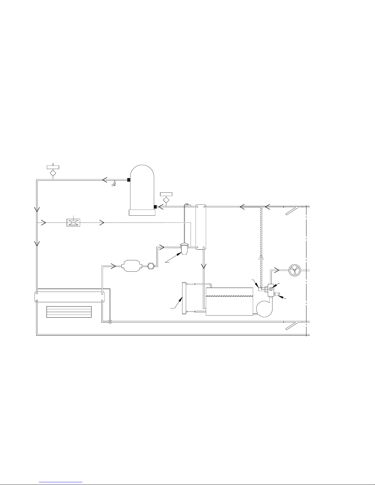
Flow Schematic – Water-Cooler Chillers
VALVE
CONDENSER WATER FLOW
FLOW DIAGRAM
WATER-COOLED
DW500
15.4 USGPM / 58.3 LPM
FLUID
PRESSURE
IN
DRAIN
SENSOR
WATER
WATER LEVEL
SIGHT GLASS
FROM
PROCESS
RESERVOIR TANK
PUMP
TO
PROCESS
TEMPERATURE
SENSOR
RTD
BYPASS
VALVE
FLOW
METER
LOW
PRESSURE
SWITCH
15 PSI CO
SUCTION
LINE
30 PSI CI
COMPRESSOR
TXV
THERMOSTATIC
EXPANSION
VALVE
FILTER
DRIER
SIGHT
GLASS
HOT GAS
BYPASS
PRESSURE
RELIEF VALVE
(675 PSI)
"Y"
STRAINER
(WITH RESET
BUTTON)
REFRIGERANT
HIGH
PRESSURE
SWITCH
(630 PSI)
REAR
PANEL
CONDENSER
IN
CONDENSER
OUT
"Y"
STRAINER
CONDENSER
WATER REGULATING
20-40 PSI / 1.4-2.4 Bar Required
110-279 47
Page 49
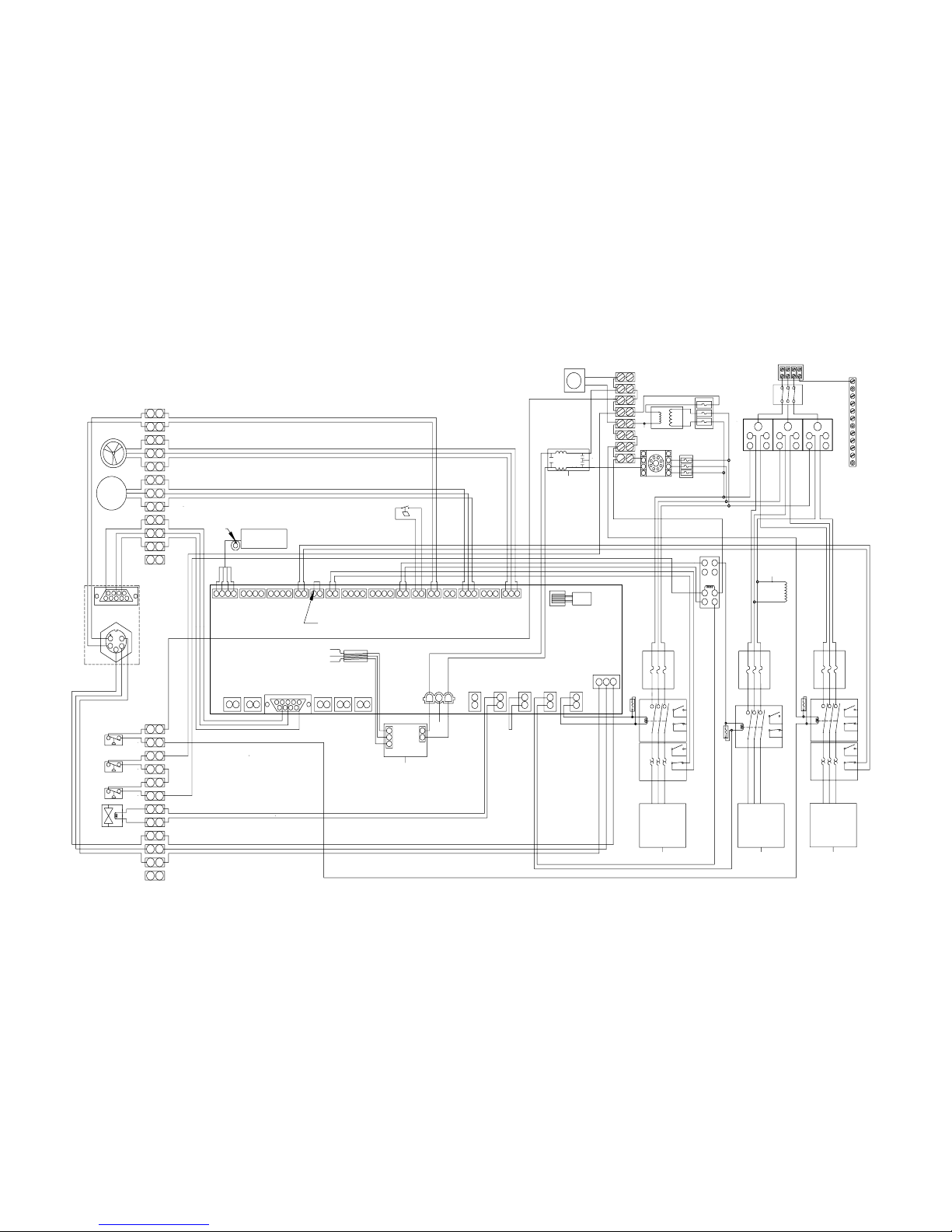
Wiring Diagram – 5 HP and 7.5 HP Air-Cooled Chillers
279 48
WIRING DIAGRAM - 5 & 7.5 HP CHILLERS
AIR-COOLED
BLU
YEL
YEL
BLK
BLK
BLU
NO
120VAC
NC
COM
WHT
BLK
BLK
BLK
BLK
WHT
CRANKCASE
HEATER
GB
GRN/YEL
BLK
WHT
FAN CYCLING
PRESSURE SWITCH
FAN
PHASE
MONITOR
G
225-130
SHUNT
REAR
PANEL
WHT
BLK
WHT
BLK
RED
BLK
BLK
17
12
15
23
10
3
9
7
21
6
8
20
24
16
18
19
13
1
4
11
22
2
14
5
21
12121
2
1
2
2
12121
2
1
121212121212
132
13213234123412
34123412
TB 3
FUSE
BLOCK
C
A
B
D
C
A
B
D
YEL
9
8
7
6
5
4
3
2
1
GROUND
BAR
TB 2
TB 2
TB 1
TB 1
STATUS ALARM CONTACTS
HOT GAS B YP A SS V A LV E
A2
A1
A2
A1
COMPRESSOR
PUMP
GRN/YEL
BLK
WHT
BLK
WHT
FLUID PRESSURE SEN SO R
FLOW METER
REMOTE CUTOFF SWITCH
BLK
BLK
YEL
YEL
BLU
BLU
WHT
BLU
RED
WHT
WHT
BLK
BLU
RED
GRN
WHT
WHT
GRN
RED
WHT
BLK
RED
BLK
GRN
BLK
GRN
RED
RED
WHT
BLK
GRN
BLK
GRN
RED
WHT
BLK
BRN
BLK
POWER
SUPPLY
GB
NC
NO
NC
NO
NO
NC
COMPR ESSO RPUMP
FUSE
BLOCK
CONTACTOR
OVERLOAD
RELAY
CONTACTOR
FUSE
BLOCK
FAN
NC
FUSE
BLOCK
OVERLOAD
RELAY
NC
NO
A1
CONTACTOR
NO
A2
DISTRIBUTION
BLOCK
FRONT PANEL
DISCONNECT
SWITCH
L3
L2L1
D
C
B
A
WHT
BLK
YEL
GRN
RED
200-284
PCB U4 PIN 1
PCB XFMR 1 PIN 10
PCB U4 PIN 4
215-513
3
1
1
2
5
200-280
BEAD
GB
EMI
FILTER
FAN
8
7
6
4
5
213
FAN(S) OVERLOA D R ELAY (N C)
PUMP OVERLO A D RELAY (NC)
GB
DCMP
DHRN PRK
DPMP DFAN
PWR
FAN HTR
OTP CMP PMP
STA
12345
6
879
1
2
123
12
3
D232
RTD 100
TEMP. SENSOR
1234
HEFHITFPS
DHPS
DLPS
R
C
V
R
C
S
F
L
W
D
A
F
2
D
A
P
1
D
A
P
2
D
A
F
1
T3
T2
T1/ITS
5
3
4
2
1
CONT 5
RS-232
637
4215
89
FLUID
PRESSURE
SENSOR
FLOW
METER
BLK
GRN
RED
HOT
GAS
BYPASS
VALVE
REFRIGERANT HIGH
PRESSURE SWITCH
REFRIGERANT LOW
PRESSURE SWITCH
13
3
16
2
21
6
9
7
20
19
15
11
22
17
1
18
12
10
8
4
23 24
14
5
GB
GB GB
L1 L2 L3
JUNCTION BO X
(REAR OF UNIT)
GROUND
SUPPLY VOLTAGE
OUTPUT
OUTPUT
GROUND
SUPPLY VOLTAGE
COM
NO
NC
NC
COM
NO
1
2
FAN
BLK WHT BLU
BRN
FLOW
SWITCH
RC
FILTER
RC
FILTER
RC
FILTER
525-814
PULLUP
RESISTORS
RJ-45
1.4A
1.4A
3.5A
MULTI -TAP
TRANSFORMER
120VAC OUTPUT
GB
FUSE
BLOCK
BLK
WHT
110-
Page 50
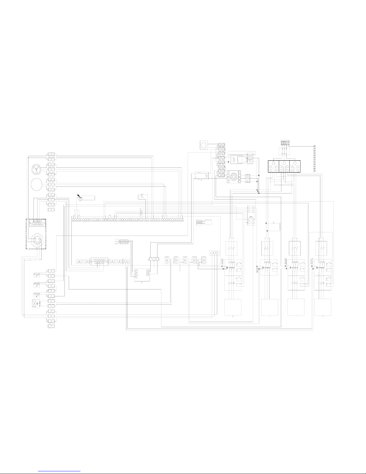
Wiring Diagram – 10 HP Air-Cooled Chillers
WIRING DIAGRAM - 10 HP CHILLERS
BLK
BLU
BLU
RC
FILTER
COM
NC
120VAC
NO
BLK
BLK
YEL
YEL
BLU
BLU
WHT
BLK
GRN/YEL
GB
CRANKCASE
HEATER
FRONT FAN
RJ-45
PULLUP
RESIST ORS
525-814
FUSE
BLOCK
GB
MULT I - TAP
TRANSF ORMER
120VAC OUTPUT
3.5A
1.4A
1.4A
A1
RC
FILTER
RC
FILTER
RC
FILTER
CONTROL P CB
500-328A-A
PHASE
MONI TOR
FLOW
SWITCH
BRN
BLU
WHTBLKBLK
REAR FAN
PANEL
2
1
NO
COM
NC
NC
NO
COM
SUPPLY VOLTAGE
GROUND
OUTPUT
OUTPUT
SUPPLY VOLTAGE
GROUND
JUNCTION BOX
(REAR OF UN I T)
L1 L2 L3 GND
GBGB
GBGB
5
14
2423
4
8
10
12
18117
22
11
15
19 20
7
9
6
21
2
16
3
13
FAN CYCLING
PRESSURE SWITCH
REFRIGERANT LOW
PRESSURE SWITCH
REFRIGERANT HIGH
PRESSURE SWITCH
HOT GAS
BYPASS
VALVE
RED
GRN
BLK
FLOW METER
FLUID
PRESSURE
SENSOR
98
512473
6
RS-232
CONT 5
1
24
3
5
T1/ITS
T2
T3
D
A
F
1
D
A
P
2
D
A
P
1
D
A
F
2
F
L
W
R
C
S
R
C
V
DLPS DHPS FPS HIT HEF
4321
RTD 10 0
TEMP. SENS OR
D232
321
32 1
21
9786
54321
STA
PMPCMPOTPHTRFAN
PWR
DFANDPMPPRKDHRN DCMP
GB
PUMP OV ERLOAD RELAY (NC)
FAN(S) OVERLO AD RELAY (NC)
3
1
2
5
4
67
8
FAN
EMI
FILTER
GB
200-280
BEAD
5
2
1
1
3
215-513
PCB U4 PIN 4
PCB XF MR 1 PIN 10
PCB U4 PIN 1
200-284
RED
GRN
YEL
BLK
WHT
ABC
D
L1 L2 L3
FRONT PANEL
DISCONNECT
SWITCH
DISTRIBUTION
BLOCK
A2
NO
CONTACTOR CONTACTOR
NO
NC
OVERLOAD
RELA Y
OVERLOAD
RELAY
FUSE
BLOCK
FUSE
BLOCK
NC
FRONT
FAN
REAR
FAN
NC
NC
NO
NO
FUSE
BLOCK
CONTACTOR
OVERLOAD
RELA Y
CONTACTOR
FUSE
BLOCK
PUMP COMP RESSO R
NC
NO
NO
NC
NO
NC
GB
POWER
SUPPLY
BLK
BRN
BLK
WHT
RED
GRN
BLK
GRN
BLK
WHT
RED
RED
GRN
BLK
GRN
BLK
RED
WHT
BLK
WHT
RED
GRN
WHT
WHT
GRN
RED
BLK
BLK
BLU
BLK
WHT
WHT
RED
BLU
WHT
BLU
BLU
YEL
YEL
BLK
BLK
REMOTE CUTOFF SWITCH
FLOW METER
FLUID PRESSURE SENSOR
WHT
BLK
WHT
BLK
GRN/YEL
PUMP
COMPRESSOR
A2
A1
A1
A2
A1
A2
BLUBLU
HOT GAS BYPASS VALVE
STATUS ALARM C O NT ACTS
TB 1
TB 1
TB 2
TB 2
GROUND
BAR
1
2
3
4
5
6
7
8
9
YEL
DB
ACDBAC
FUSE
BLOCK
TB 3
2143 2143 2 143 2143
231 231 231212121
212121
12
121212
2121212
1
12
5
14
2
22
11
4
1
13
19
18
16
24
20
8
6
21
7
9310
23
15
12
17
BLK
BLK
RED
BLK
WHT
BLK
WHT
BLK
REAR
FRONT FAN
110-279 49
Page 51
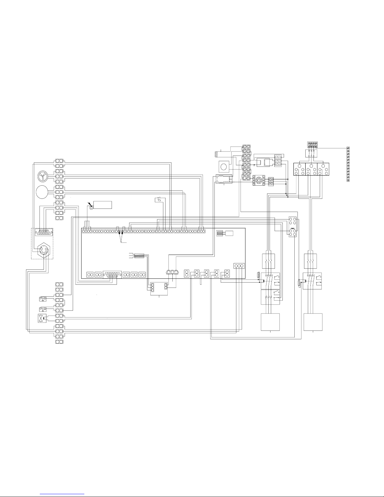
Wiring Diagram – 5 HP Water Cooled Chillers
WHT
COM
NC
120VAC
NO
BLU
BLK
BLK
YEL
YEL
BLU
1.4A
1.4A
3.5A
MULTI -TAP
TRANSFOR M ER
120VAC OUTPUT
GB
FUSE
BLOCK
PHASE
MONITOR
G
225-130
SHUNT
REAR
PANEL
WHT
BLK
WHT
BLK
RED
BLK
BLK
17
12
15
23
10
3
9
7
21
6
8
20
24
16
18
19
13
1
4
11
22
2
14
5
2
1
12121
2
1
2
21212
1
2
1
121
2
12121212
132
132132341
2
341
2
34123412
TB 3
FUSE
BLOCK
C
A
B
D
C
A
B
D
YEL
9
8
7
6
5
4
3
2
1
GROUND
BAR
TB 2
TB 2
TB 1
TB 1
STATUS ALARM CONTACTS
HOT GAS BYPASS VALVE
A2
A1
A2
A1
COMPRESSOR
PUMP
GRN/YEL
BLK
WHT
BLK
WHT
GRN/YEL
BLK
WHT
FLUID PRESSURE SENSOR
FLOW METER
REMOTE CUTOFF SWITCH
YEL
YEL
WHT
BLU
RED
WHT
WHT
BLK
BLU
RED
GRN
WHT
WHT
GRN
RED
WHT
BLK
RED
BLK
GRN
BLK
GRN
RED
RED
WHT
BLK
GRN
BLK
GRN
RED
WHT
BLK
BRN
BLK
POWER
SUPPLY
GB
GB
NC
NO
NC
NO
NO
NC
COMPRESSORPUMP
FUSE
BLOCK
CONTACTOR
OVERLOAD
RELAY
CONTACTOR
FUSE
BLOCK
DISTRIBUTION
BLOCK
FRONT PANEL
DISCONNECT
SWITCH
L3
L2L1
D
C
B
A
WHT
BLK
YEL
GRN
RED
200-284
PCB U4 PIN 1
PCB XFMR 1 PIN 10
PCB U4 PIN 4
215-513
3
1
1
2
5
200-280
BEAD
GB
EMI
FILTER
CRANKCASE
HEATER
FAN
8
7
6
4
5
213
PUMP O V ERLOAD RELAY (NC)
GB
DCMP
DHRN PRK
DPMP DFAN
PWR
FAN HTR O TP CMP PMP
STA
12345
6879
1
2
123
123
D232
RTD 100
TEMP. SENSOR
1234
HEFHITFPS
DHPS
DLPS
R
C
V
R
C
S
F
L
W
D
A
F
2
D
A
P
1
D
A
P
2
D
A
F
1
T3
T2
T1/ITS
5
3
4
2
1
CONT 5
RS-232
637
4215
89
FLUID
PRESSURE
SENSOR
FLOW
METER
BLK
GRN
RED
HOT
GAS
BYPASS
VALVE
REFRIGERANT HIGH
PRESSURE SWITCH
REFRIGERANT LOW
PRESSURE SWITCH
13
3
16
2
21
6
9
7
20
19
15
11
22
17
1
18
12
10
8
4
23 24
14
5
GB GB
L1 L2 L3
JUNCTION BO X
(REAR OF UNIT)
GROUND
SUPPLY VOLTAGE
OUTPUT
OUTPUT
GROUND
SUPPLY VOLTAGE
COM
NO
NC
NC
COM
NO
1
2
BLK WHT
BLU
BRN
FLOW
SWITCH
RC
FILTER
RC
FILTER
525-814
PULLUP
RESISTORS
RJ-45
WIRING DIAGRAM - 5 HP CHILLERS
WATER-COOLED
BLU
BLU
110-279 50
Page 52

4-20 mA Set Point Control
This feature is optional and may not appear in your version of software. To enable it, go the Current Control (CC) in the Operational Parameters menu and set
to YES.
If current input is outside 4-20 mA, ECC (Error Current Control) will be displayed and the pump, compressor, and fan will turn Off. Sending an in-range input
will restart the Chiller.
0.32 mA per °C 0.1778 mA per °F
°C mA
°C mA
°C mA
°F mA
°F mA
°F mA
°F mA
°F mA
-10 4.000 7 9.440 24 14.880 14 4.000 33 7.378 52 10.756 71 14.133 90 17.511
-9 4.320 8 9.760 25 15.200 15 4.178 34 7.556 53 10.933 72 14.311 91 17.689
-8 4.640 9 10.080 26 15.520 16 4.356 35 7.733 54 11.111 73 14.489 92 17.867
-7 4.960 10 10.400 27 15.840 17 4.533 36 7.911 55 11.289 74 14.667 93 18.044
-6 5.280 11 10.720 27 16.160 18 4.711 37 8.089 56 11.467 75 14.844 94 18.222
-5 5.600 12 11.040 29 16.480 19 4.889 38 8.267 57 11.644 76 15.022 95 18.400
-4 5.920 13 11.360 30 16.800 20 5.067 39 8.444 58 11.822 77 15.200 96 18.578
-3 6.240 14 11.680 31 17.120 21 5.244 40 8.622 59 12.000 78 15.378 97 18.756
-2 6.560 15 12.000 32 17.440 22 5.422 41 8.800 60 12.178 79 15.556 98 18.933
-1 6.880 16 12.320 33 17.760 23 5.600 42 8.978 61 12.356 80 15.773 99 19.111
0 7.200 17 12.640 34 18.080 24 5.778 43 9.156 62 12.533 81 15.911 100 19.289
1 7.520 18 12.960 35 18.400 25 5.956 44 9.333 63 12.711 82 16.089 101 19.467
2 7.840 19 13.280 36 18.720 26 6.133 45 9.511 64 12.889 83 16.267 102 19.644
3 8.160 20 13.600 37 19.040 27 6.311 46 9.689 65 13.067 84 16.444 103 19.822
4 8.480 21 13.920 38 19.360 28 6.489 47 9.867 66 13.244 85 16.622 104 20.000
5 8.800 22 14.240 39 19.680 29 6.667 48 10.044 67 13.442 86 16.800
6 9.120 23 14.560 40 20.000 30 6.844 49 10.222 68 13.600 87 16.978
31 7.022 50 10.400 69 13.778 88 17.156
32 7.200 51 10.578 70 13.956 89 17.333
110-279 51
 Loading...