

PolyScience DuraChill 58 Series, DuraChill 68SS Series, DuraChill 69 Series, DuraChill 59 Series User Manual
Page 1
User Guide
DuraChill Air- and Water-Cooled 1.5 HP Chillers
27 June 2016
110-392
Page 2

Page 3

Table of Contents
Introduction ...............................................................................................................................................................3
General Safety Information .....................................................................................................................................3
Safety Recommendations .......................................................................................................................................3
Regulatory and Compliance Testing ...................................................................................................................5
Contents .................................................................................................................................................................5
Controls and Components ......................................................................................................................................6
Control Panel .......................................................................................................................................................6
Front ....................................................................................................................................................................6
Rear -- 230V, 240V, and 208-230V Units ...........................................................................................................7
Rear -- 380V and 460V Units ..............................................................................................................................7
Quick Start .................................................................................................................................................................8
Installation and Startup ............................................................................................................................................9
Site Requirements ...................................................................................................................................................9
Ambient Temperature and Relative Humidity .....................................................................................................9
Location ...............................................................................................................................................................9
Clearance ............................................................................................................................................................9
External Piping ..................................................................................................................................................... 10
General Considerations .................................................................................................................................... 10
Process Fluid Connections ............................................................................................................................... 11
Facility Water Connections ............................................................................................................................... 11
Reservoir Drain................................................................................................................................................. 11
Reservoir Vent .................................................................................................................................................. 11
Process Coolant ................................................................................................................................................... 12
Electrical Power ................................................................................................................................................... 13
Phase Requirements (if applicable) ................................................................................................................. 13
Optional Signal Inputs/Outputs ............................................................................................................................ 13
Ambient / External Temperature Probe ............................................................................................................ 13
RS-232/RS-485 Serial Output .......................................................................................................................... 13
Remote On / Off Port ........................................................................................................................................ 13
4-20mA Set Point Control ................................................................................................................................. 13
Startup .................................................................................................................................................................. 14
Facility Water Flow (water-cooled units only) ................................................................................................... 14
Filling the Reservoir .......................................................................................................................................... 14
Starting Process Fluid Flow .............................................................................................................................. 14
Normal Operation .................................................................................................................................................. 15
Selecting the Temperature Unit ........................................................................................................................... 15
Displaying and Adjusting the Set Point ................................................................................................................ 15
Selecting the Internal / External Temperature Display ........................................................................................ 15
Displaying and Adjusting the Ambient Tracking Offset ........................................................................................ 16
Displaying and Adjusting the Remote Control Temperature ............................................................................... 16
Selecting the Pressure / Flow Rate Display and Units ........................................................................................ 16
Setting Operational Parameters / Limits .............................................................................................................. 17
Display, Alarm and Error Messages .................................................................................................................... 20
Adjusting the High Pressure Bypass Setting ..................................................................................................... 22
Enabling / Disabling the Local Lockout .............................................................................................................. 22
Over-Temperature Protection ............................................................................................................................... 23
Routine Maintenance............................................................................................................................................. 24
Routine Maintenance ........................................................................................................................................... 24
Condenser, Air Vents and Reusable Filter ....................................................................................................... 24
Inline Strainer ................................................................................................................................................... 24
110-392 1
Page 4

Fluid Level ........................................................................................................................................................ 24
Cleaning ........................................................................................................................................................... 24
Temperature Calibration ....................................................................................................................................... 25
Internal Calibration Offset (c1) ............................................................................................................................. 25
External Calibration Offset (c2) ............................................................................................................................ 25
Flow Rate Calibration (Fc) .................................................................................................................................... 26
Fuse Bits (Fb) ......................................................................................................................................................... 26
Troubleshooting .................................................................................................................................................... 27
Diagnostic Mode .................................................................................................................................................. 28
Technical Information ........................................................................................................................................... 29
Controller Specifications ...................................................................................................................................... 29
Performance Specifications ................................................................................................................................. 29
Electrical Specifications ....................................................................................................................................... 30
Pump Performance .............................................................................................................................................. 31
RS-232 / RS-485 Communications ....................................................................................................................... 32
Certificate of Compliance ..................................................................................................................................... 33
Equipment Disposal (WEEE Directive) ................................................................................................................ 33
Service and Technical Support ............................................................................................................................ 33
Replacement Parts .............................................................................................................................................. 34
Pumps .................................................................................................................................................................. 35
Warranty ................................................................................................................................................................. 36
Appendix ................................................................................................................................................................ 37
Flow Schematic - All Models ................................................................................................................................ 37
Electrical Diagram – 208-230V / 1PH / 50-60 Hz Models without heater option ................................................. 38
Electrical Diagram – 208-230V / 1PH / 50-60Hz Models with heater option ....................................................... 39
Electrical Diagram – 208-230V and 380-460V / 3PH / 50-60Hz Models without heater option .......................... 40
Electrical Diagram - 208-230V and 380-460V / 3 PH / 50-60Hz Models with heater option ............................... 41
Options ................................................................................................................................................................. 42
General Options Wiring .................................................................................................................................... 42
RS-485 Communications Wiring ...................................................................................................................... 42
DI Control Wiring .............................................................................................................................................. 43
H2 & H3 Option Wiring ..................................................................................................................................... 43
4-20 mA Set Point Control ................................................................................................................................ 44
..............
110-392 2
Page 5
Introduction
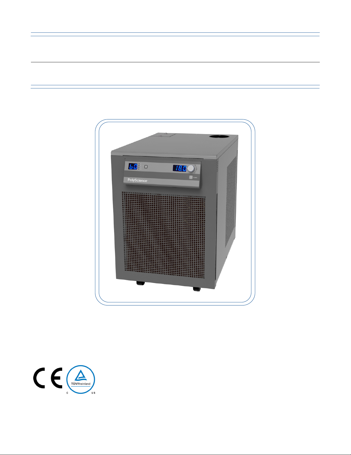
DuraChill Chillers provide cooling power for demanding applications and serve as an economical alternative to tap
water cooling systems. All models feature a microprocessor-based controller, digital Temperature Display (°C or
°F), one-touch set point display, and digital Pressure/Flow Rate Display (PSI, kPa, GPM, LPM) with push-Button
selection. To optimize cooling efficiency and performance, these sophisticated Chillers also feature a modulated
refrigeration system. As a result, temperature stability is greatly enhanced and compressor life extended.
General Safety Information
When installed, operated, and maintained according to the directions in this manual and common safety
procedures, your Chiller should provide safe and reliable temperature control. Please ensure that all individuals
involved in the installation, operation, or maintenance of this Chiller read this manual thoroughly prior to working
with the unit.
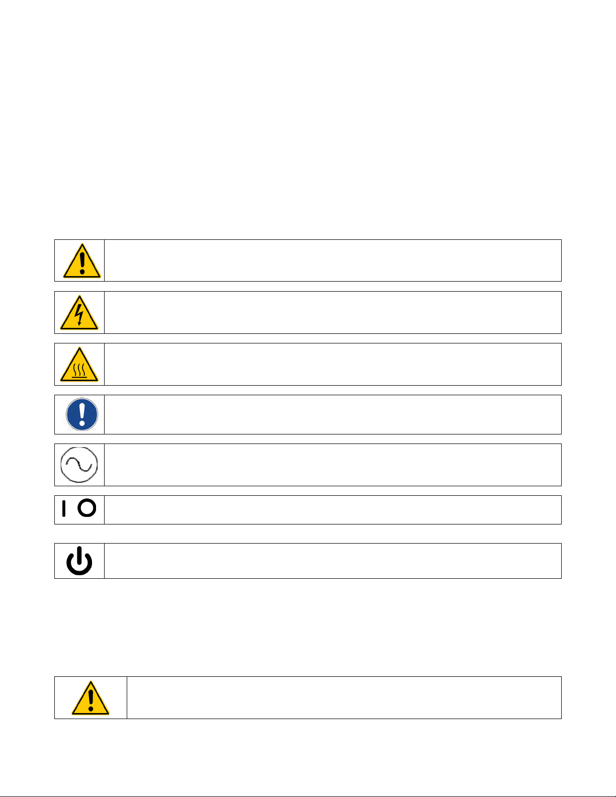
This symbol alerts you to a wide range of potential dangers. When attached to the unit, consult the operator's
manual.
This symbol advises danger from electricity or electric shock.
This symbol indicates that a hot surface may be present.
This symbol marks information that is particularly important.
This symbol indicates alternating current.
/
These symbols on the Power Switch / Circuit Breaker indicate that they place the main power supply ON / OFF.
This symbol on the Power Key (if present) indicates that it places the unit in a standby mode. It DOES NOT
fully disconnect the unit from the power supply.
Read all instructions pertaining to safety, set-up, and operation.
Proper operation and maintenance is the user’s responsibility
Safety Recommendations
It is the user’s responsibility to read and understand all instructions and safety precautions included in this manual
prior to installing or operating this equipment. Contact our Customer Service Department with any questions
regarding the operation of this Chiller or the information contained in this manual.
WARNING: Installation, operation, or maintenance of this equipment should be performed in strict
accordance with the instructions outlined in this manual. Failure to follow those instructions may increase
the risk of personal injury, damage the equipment, and/or void the warranty.
110-392 3
Page 6
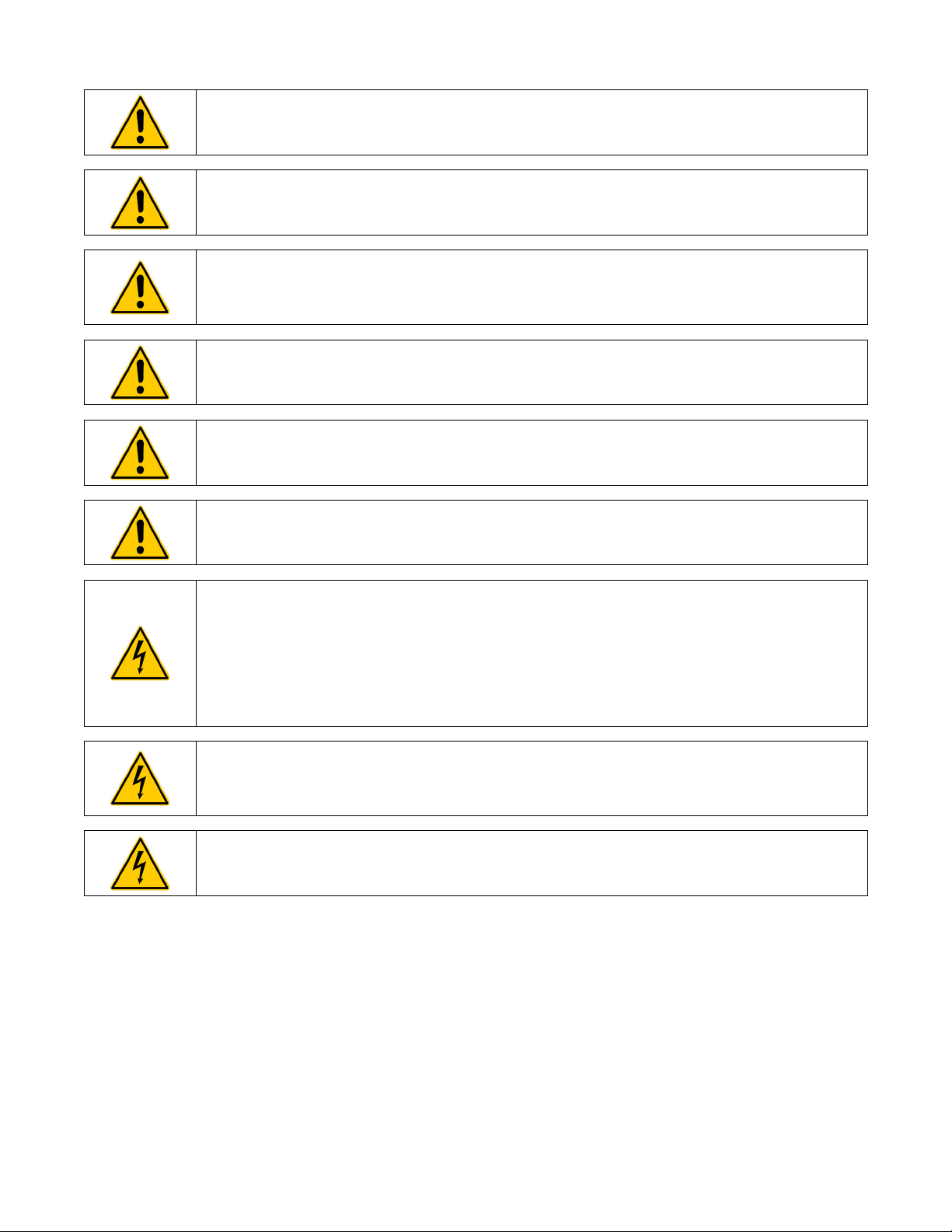
WARNING: Always operate the unit within the stated temperature and pressure design specifications.
WARNING: All warning labels should be carefully observed. Never remove or obstruct a warning label.
WARNING: Units which use cooling fluid must be properly filled before use and properly drained before
moving or service. Allow reservoir fluid to return to ambient temperature before draining. Be sure to follow
your organization's procedures and practices regarding the safe lifting and relocation of heavy objects.
For items weighing 18 kg or more, safe practice lifting should be performed by at least two people.
WARNING: Service should only be performed by fully qualified personnel. Extreme caution is required as
hazards are present when servicing this equipment.
WARNING: Do not attempt to operate leaking or damaged equipment.
CAUTION: Be sure to follow all appropriate safety and environmental guidelines when collecting and
disposing of spent coolant.
WARNING:
Do not plug unit into the electrical outlet until it is ready for startup.
Always connect the power cord on this unit to a grounded power outlet. Make certain that the outlet is the
same voltage and frequency as your unit (see identification label). Never operate the unit with a damaged
power cord.
Always turn the unit OFF and disconnect mains power before performing any maintenance or service as
hazardous voltages exist within chassis components.
WARNING: Make sure the equipment's main power switch is in the OFF position before connecting or
disconnecting electrical power from the unit. Follow all applicable electrical and safety codes and
procedures when connecting power to the unit. Electrical connections should be made by an authorized
electrical installer.
WARNING: Disconnect electrical power before moving the unit. Keep unit upright when moving. Follow
your company's procedures and practices regarding the safe lifting and relocation of heavy objects. For
items weighing 18 kg or more, safe practice lifting should be performed by at least two people.
110-392 4
Page 7

Regulatory and Compliance Testing
Canada USA (60Hz) units
CAN/CSA C22.2 No. 61010-1-12 – Safety Requirements for Electrical Equipment for Measurement, Control and Laboratory
Use, Part I: General Requirements.
CAN/CSA C22.2 No. 61010-2-010-04 (R2014) – Safety Requirements for Electrical Equipment for Measurement, Control
and Laboratory Use – Part 2-010: Particular Requirements for Laboratory Equipment for the Heating of Materials.
UL Std No. 61010-1 (2012) – Safety Requirements for Electrical Equipment for Measurement, Control and Laboratory Use –
Part 1: General Requirements.
UL Std No. 61010-2-010 (2015) – Safety Requirements for Electrical Equipment for Measurement, Control and Laboratory
Use – Part 2-010: Particular Requirements for Laboratory Equipment for the Heating of Materials.
CE (50Hz units)
Machinery Directive 2006/42/EC
EC Electromagnetic Compatibility Directive 2014/30/EU
IEC 61010-1 / EN 61010-1:2010
IEC 61010-2-010 / EN 61010-2-010:2014
IEC 61326:2012 / EN 61326:2013
RoHS Directive 2011/65/EU
Australia/New Zealand (50 Hz)
ACMA – Radiocommunications (Electromagnetic Compatibility) Standard 2008 EN 61326-1:2013
EAC Customs Union (50 Hz)
TP TC 010/2011 On Safety of Machinery and Equipment
TP TC 004/2011 On Safety of Low Voltage Equipment
TP TC/020/2011 Electromagnetic Compatibility of Technical Equipment
Highly Accelerated Life Test (HALT) and Vibration Tests per ASTM D4169-8 (All units)
Contents
The following items have been included with your Chiller:
• Operator’s Manual
• Two sets of Inlet/Outlet Adapters: ½ inch male NPT x ½ inch hose barb and ½ inch male NPT x 5/8 inch hose
barb (select models)
110-392 5
Page 8
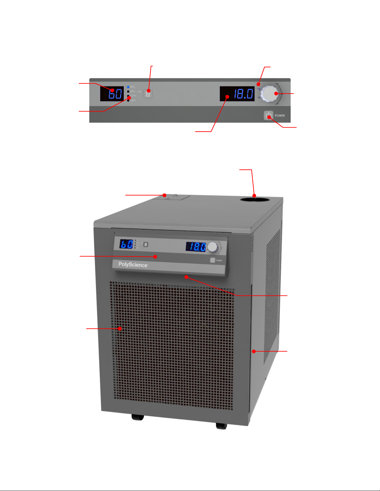
Controls and Components
Reservoir Cap
Pressure / Flow
Rate Display
Pressure / Flow
Rate Units
Unit / Menu Select Button
Air Filter
Temperature Display
Select / Set Knob
Power Button
Temperature Units
Control Panel
Bypass Valve Access Panel
Air Filter Access
Ambient / External
Temperature Tracking
Probe
(optional)
Control Panel
Front
110-392 6
Connection
Page 9
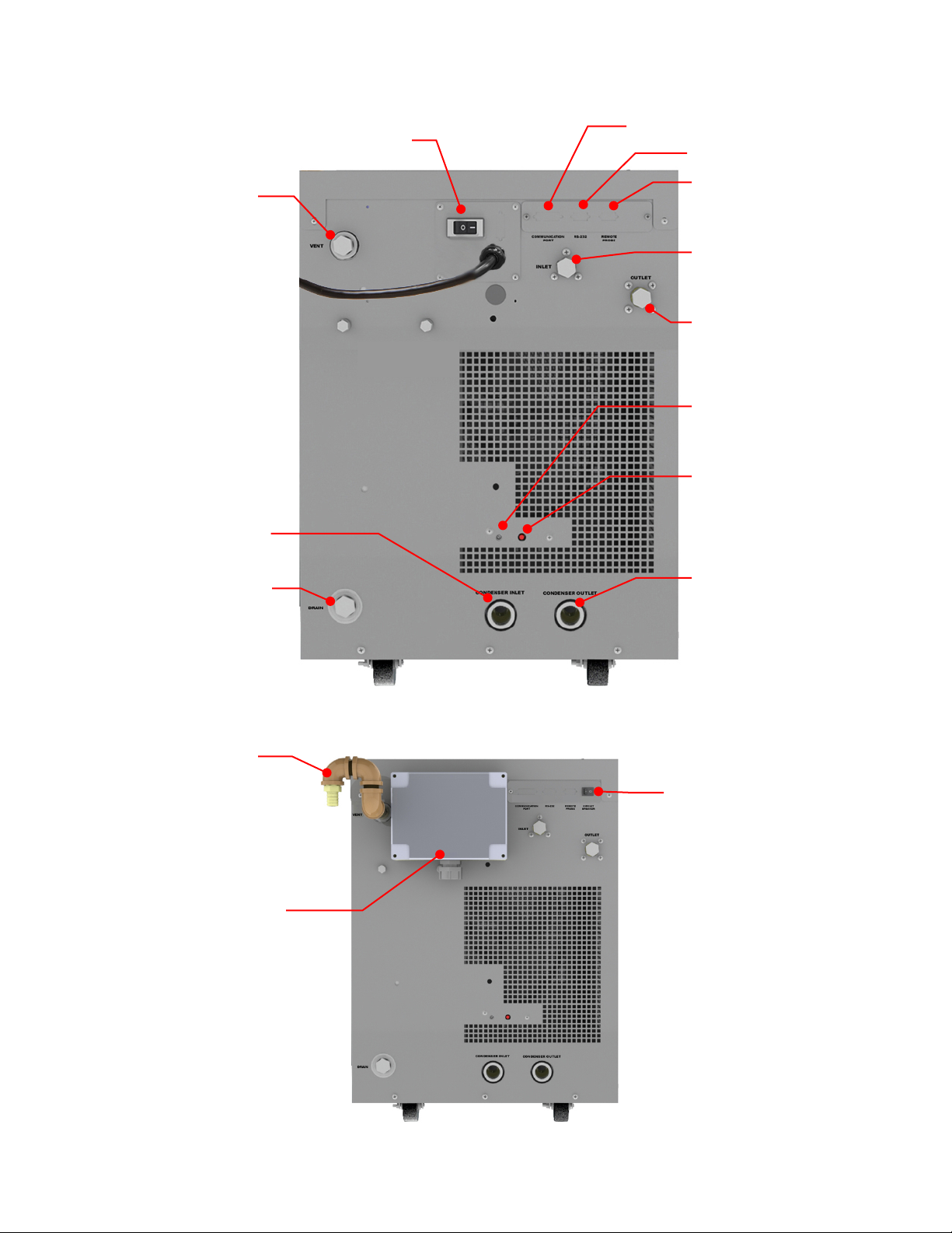
Rear – 230V, 240V, and 208-230V Units
Communications Port (optional)
RS-232 Port (optional)
Remote Temperature
Probe Port (optional)
Power Switch / Circuit Breaker
Reservoir Vent
(Vent Assembly required
on 5XXX models)
Fluid Inlet (from process)
Fluid Outlet (to process)
Facility Water Outlet
(water
Facility Water Inlet
cooled models)
Reservoir Drain
Over-Temperature
Protection Adjust
(5XXX models only)
Over-Temperature Protection
Reset (5XXX models only)
Vent Assembly
(supplied with
5XXX models)
Electrical Connections
Junction Box
Power Switch
(water-
Rear – 380V and 460V Units
-cool models)
110-392 7
Page 10
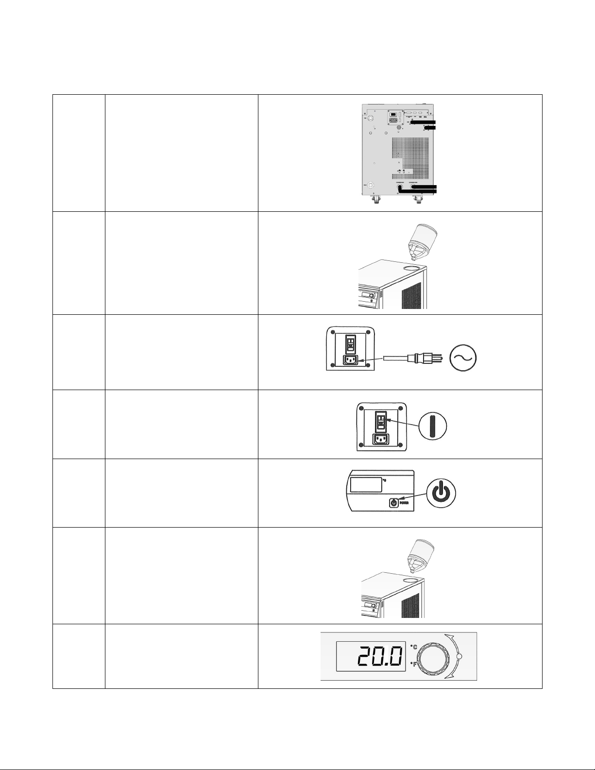
Quick Start
See Installation & Startup for additional information.
All units:
Connect process lines
1
2
3
4
Water-cooled units:
A. Connect process lines
B. Connect facility water lines
C. Turn facility water ON
Fill reservoir with coolant
Connect electrical power to
Mains
Turn Power Switch / Circuit
Breaker ON
5
6
7
110-392 8
Turn Controller ON
Add coolant to reservoir as
process lines fill
Enter temperature set point
Page 11

Installation and Startup
Site Requirements
Ambient Temperature and Relative Humidity
The Chiller is designed for indoor installation in ambient temperatures between 16° and 35°C (60° and 95°F);
relative humidity should not exceed 80% (non-condensing).
Location
Install the Chiller on a strong, level surface as close to possible to the process requiring cooling. It should not be
installed closer than 4 feet (1.4 meters) to a heat-generating source. If possible, the unit should be located near a
suitable drain to prevent flooding in the event of leaks. Do not place it where corrosive fumes, excessive moisture,
excessive dust, or high room temperatures are present.
Position the Chiller as close as possible to the power distribution panel. Avoid voltage drops by using a properly
grounded power source wired to meet electrical data plate requirements. The use of an extension cord is not
recommended.
NOTE: The unit may be located at a level below that of the equipment being cooled. As long as the process
remains closed, overflow will not occur when adding cooling fluid to the unit's reservoir.
Clearance
Allow adequate clearance on the front, sides, and rear of the Chiller for access to connections and components.
The front and rear vents of the Chiller must be a minimum of 24 inches (61 cm) away from walls or vertical
surfaces so air flow is not restricted.
110-392 9
Page 12
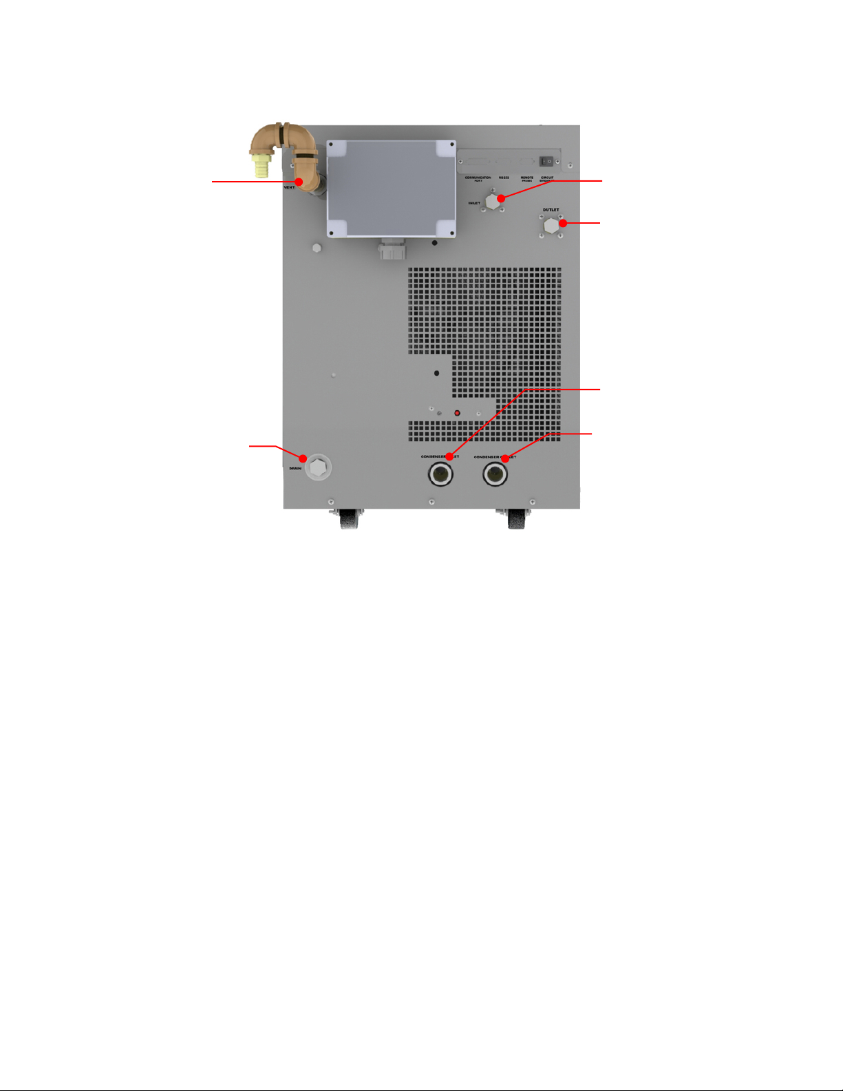
External Piping
Facility Water Outlet
Facility Water Inlet
Reservoir Drain
Reservoir Vent
(shown with Vent
Assembly for
5XXX models))
Process Fluid Inlet
Process Fluid Outlet
General Considerations
It is the user’s responsibility to ensure that the tubing and fittings connected to the Chiller are compatible with the
fluid, temperature, and pressure being used.
• All external piping, tubing, or hoses should be run full size to limit the potential for external pressure drops.
The use of quick-connect fittings is not recommended, as they can cause substantial pressure drops.
• Materials of construction should be compatible with the fluid being used as well as the temperature and
pressure at which the unit will operate.
• Where applicable, always use a back-up wrench when making piping connections to the Chiller.
• Pressure Ratings – Hoses should be able to withstand the highest pressure that they will encounter (100 psi
/ 6.9 bar).
• Flexible Tubing – Avoid tubing that will expand and increase fluid volume when operating at the desired
pressure.
• Hose Diameter – The fittings on the Chiller’s process fluid lines are female 0.5 in NPT. The facility water fluid
inlets and outlets on water-cooled models are female 0.75 inch NPT.
• Facility Water (water-cooled models only) – Should be clean and well maintained. Ideally, the facility water
should be tested monthly to ensure a pH level between 7.2 and 7.8. Add algaecide if algae growth is
present.
110-392 10
Page 13

Process Fluid Connections
The incoming cooling water pressure should be 20 psi / 1.4 bar minimum and 150 psi / 10.3 bar
The Chiller has two internally threaded fittings on the rear of the instrument housing for the process water
connections. Two sets of adapters are supplied with the unit for connecting these fittings to the process piping.
The direction of the flow through the system can be controlled by the way the connections are made. Fluid is
drawn into the Chiller through the “Inlet” connection; fluid is pumped out of the Chiller through the “Outlet”
connection.
NOTE: When Chillers with the standard magnetic drive centrifugal pump are connected to an external
apparatus with a built-in shutoff, an external bypass loop assembly (Part No. 510-147) may be needed if
operating below 20°C (68°F). This bypass assembly continues flow circulation to and from the pump even
though the main flow to the external apparatus has been blocked.
Facility Water Connections
WARNING: On units requiring facility water, those connections must be made by a licensed plumber.
CAUTION:
maximum.
Water-cooled Chillers have two internally threaded fittings on the rear of the instrument housing for the facility
water connections. The cooling water supply should be connected to the facility water inlet on the Chiller. The
facility water outlet on the Chiller should be connected to the appropriate return or drain, as required.
The cooling water supply may be from city tap water or a cooling tower. The incoming water pressure should be
between 20 and 150 psi / 1.4 and 10.3 bar.
Reservoir Drain
A connection is provided for the reservoir’s gravity drain.
Reservoir Vent
A reservoir vent assembly is provided with Chillers equipped with the heater option to relieve pressure within the
reservoir as coolant heats and expands. A connection is provided on the rear of the Chiller for the vent assembly.
110-392 11
Page 14
Process Coolant
Suitable Fluids
WARNING: For units that use cooling fluids.
Use only fluids that comply with safety, health, and equipment compatibility requirements. Read the safety
data sheet for the fluid being used carefully before use.
CAUTION: DO NOT USE
Caustic, corrosive, or flammable liquids
Automotive anti-freeze*
Hard tap water*
Deionized water with a specific resistance >1 meg ohm
Concentrations of acids or bases
Solutions with halides: chlorides, fluorides, bromides, iodides, or sulfur
Chlorine bleach
Glycerine
Syltherm fluids
At temperatures above 40°C, additives or mineral deposits can adhere to the heater. If deposits are allowed to build up,
*
the heater may overheat and fail. Higher temperatures and higher concentrations of additives will hasten mineral
deposits
The Chiller can accommodate a variety of coolant fluids (water, glycol mixtures, etc). For most applications above 20°C (68°F),
distilled water is satisfactory. For operation below 20°C (68°F), the Chiller must be protected with an antifreeze solution.
Ethylene glycol (laboratory grade) and water in a 50/50 mixture is satisfactory from +20° to -15°C (68° to 5°F). Select a fluid
that is compatible with the Chiller’s wetted parts (brass, bronze, stainless steel, EPDM rubber, nylon, PVC).
WARNING: Operation below 20°C (68°F) requires antifreeze in the circulation fluid. Do not use automotive
antifreeze as the additives may be harmful to the Chiller's wetted parts.
110-392 12
Page 15

Electrical Power
WARNING:
Do not plug unit into the electrical outlet until it is ready for startup.
Always connect the power cord on this unit to a grounded power outlet. Make certain that the outlet is the
same voltage and frequency as your unit (see identification label). Never operate the unit with a damaged
power cord.
Always turn the unit OFF and disconnect mains power before performing any maintenance or service as
hazardous voltages exist within chassis components.
WARNING: Make sure the equipment's main power switch is in the OFF position before connecting or
disconnecting electrical power from the unit. Follow all applicable electrical and safety codes and procedures
when connecting power to the unit. Electrical connections should be made by an authorized electrical
installer.
WARNING: DO NOT apply power until the unit is ready for Startup.
Connect the power cord (if) supplied with the Chiller to an appropriate electrical outlet.
Phase Requirements (if applicable)
For 3-phase units, be sure to connect in proper sequence, ie.: L1, L2, and L3. These Chillers are designed with a
junction box on the rear of the unit to which you can connect the electrical power supply conduit. Be sure to
provide suitable conduit strain relief and grounding.
3-phase units are equipped with a phase monitor that prevents startup if phase sequence is incorrect. The Chiller
will turn OFF in the event of a loss of one phase and/or prevent operation if there is a voltage mismatch between
any two phases greater than 8%.
Optional Signal Inputs/Outputs
Ambient / External Temperature Probe
Allows control of the cooling fluid temperature using an external temperature measurement (ambient
room/machine temperature or process temperature). A 9-pin connector is provided for connecting the
ambient/external tracking probe.
NOTE: In order for the Chiller to properly recognize the presence of the external temperature probe, the
probe must be connected to the unit before power is applied..
RS-232 / RS-485 Serial Output
Allows remote control the Chiller and/or the output of temperature readings to an external auxiliary device. The
maximum communications distance for Chillers equipped with the RS232 option is 50 feet (15 meters). The
maximum distance for units equipped with the RS485 option is 4000 feet (1200 meters). A 9-pin D-connector is
provided for this connection.
Remote On / Off Port
Allows the connection of a remote On/Off switch or other remote control device to the Chiller. A 15-pin Dconnector is provided on the rear of the instrument enclosure for this connection.
4-20mA Set Point Control
Allows set point changes using a customer supplied current value. A 15-pin D-connector or 8-pin circular
connector is provided for this connection.
110-392 13
Page 16
Startup
Facility Water Flow (water-cooled units only)
1. Open the valves to the facility water supply and return.
2. Check for leaks.
Filling the Reservoir
1. Remove the reservoir cap located on the top of the Chiller and, using a funnel, add fluid until it is
approximately 2 inches (5.1 cm) below top of reservoir.
2. Once the fluid level is about 2 inches (5.1 cm) below the top of the reservoir, remove the funnel but do not
replace the cap at this time.
Starting Process Fluid Flow
1. Place the circuit breaker located on the rear panel of the Chiller to the ON position. The display on the front
panel will respond by showing standby (....). If there is no response, check that the unit is connected to
working electrical power and that circuit breaker on the rear of the Chiller is in the ON position.
2. Press the Power Button on the front panel. The system startup sequence will begin and proceed as follows:
• The pump will turn on and fluid will begin circulating through the system.
• The set point temperature will appear briefly on the Temperature Display; after a few seconds, it will be
replaced by the actual fluid temperature.
• 15 to 20 seconds after power up, the compressor will begin operating.
NOTE: When adding fluid to the unit for the first time, prime the pump by pressing the Power Button to turn
power ON, letting the Chiller run for 3 seconds, and the pressing the Power Button again to turn power OFF.
Repeat this ON and OFF procedure three times.
3. Check for leaks.
4. With the pump running, the reservoir’s fluid level will drop as the process and/or process cooling lines fill
with fluid. Slowly add fluid to the reservoir until the liquid level remains stable.
5. Replace the reservoir cap.
110-392 14
Page 17

Normal Operation
NOTE: The Chiller incorporates a special "lockout" feature that can be enabled to prevent unauthorized or
accidental set point and other operational changes. This feature is described in detail under "Enabling and
Disabling the Local Lockout." It should not be enabled until all operational parameters have been set.
Selecting the Temperature Unit (°C or °F)
The LEDs adjacent to the Temperature Display indicate the unit (°C or °F) used for Temperature Displays.
To change from °C to °F or vice versa, proceed as follows:
To change to °F — Place the Circuit Breaker/Power Switch on the rear of the instrument in the OFF
position. Press and hold the Units/Menu Select Button while returning the Circuit Breaker/Power Switch
to the ON position.
To change to °C — Place the Circuit Breaker/Power Switch on the rear of the instrument in the OFF
position. Press and hold the Power Button on the front panel while returning the Circuit Breaker/Power
Switch to the ON position.
IMPORTANT: All user settings, except baud rate and calibration offset, return to the original factory defaults
when the temperature unit is changed. The Chiller's temperature set point and various alarm settings should
be reset to desired values.
Displaying and Adjusting the Set Point
Press the Select/Set Knob on the front panel. The current set point temperature will be displayed, and the decimal
point at the bottom right of the display will flash, indicating that the temperature can be changed.
Rotate the Select/Set Knob until the desired set point temperature is displayed. The setting is accepted after the
Select/Set Knob is pressed a second time or automatically after a few seconds of inactivity.
NOTE: Temperature set point cannot be changed when the local lockout is enabled or remote temperature
control is installed and enabled. It allows the user to check or continuously display either the Chiller's internal
outlet fluid temperature or the external ambient/process temperature.
Selecting the Internal / External Temperature Display
NOTE: This section applies only when the ambient tracking probe or remote temperature control is installed
and enabled. It allows the user to check or continuously display either the Chiller's internal outlet fluid
temperature or the external ambient/process temperature.
When the ambient tracking probe is selected (AtC), the Chiller normally displays the internal outlet fluid
temperature. To display the external ambient temperature, press and release the Units/Menu Select Button until
P2 appears on the Pressure/Flow Rate Display.
When the remote temperature control probe is selected (rPC), the Chiller normally displays the external process
temperature. To display the internal outlet fluid temperature, press and release the Units/Menu Select Button until
P1 appears on the Pressure/Flow Rate Display.
NOTE: P1 or P2 will remain on the pressure/flow rate display until the Units/Menu Select button is pressed
and released. The displayed temperature will revert to the default condition (internal temperature for the
ambient probe, external temperature for the remote temperature control probe).
110-392 15
Page 18

Displaying and Adjusting the Ambient Tracking Offset
NOTE: Ambient tracking is an optional function that may or may not be available on your Chiller. It permits
you to control fluid temperature based on room or machine temperature plus or minus a user-adjustable
offset temperature.
When the optional ambient tracking probe is installed and enabled (AtC), the ambient tracking offset rather than
the set point temperature is displayed when the Select/Set Knob on the front panel is pressed.
To change the displayed offset value, rotate the Select/Set Knob until the desired offset value is displayed. An
offset value from -5.0°C to +5.0°C (-9.0° to +9.0°F) may be entered. The setting is accepted after the Select/Set
Knob is pressed a second time or automatically after a few seconds of inactivity.
Displaying and Adjusting the Remote Control Temperature
NOTE: Remote temperature control is an optional function that may or may not be available on your Chiller.
It permits you to control cooling based on the temperature of the external process.
When the optional remote control external probe is installed and enabled (rP), the external temperature set point
is displayed when the Select/Set Knob on the front panel is pressed.
To change the external temperature set point, press and then rotate the Select/Set Knob until the desired set
point temperature is displayed. The setting is accepted after the Select/Set Knob is pressed a second time or
automatically after a few seconds of inactivity.
Selecting the Pressure / Flow Rate Display and Units
The Chiller can set to display either fluid pressure (in PSI or kPa) or flow rate (in GPM or LPM). Pressing the
Units/Menu Select Button briefly toggles through the available selections.
NOTE: Metric pressure reading output is displayed in kPA and must be multiplied by 100 for Pa.
NOTE: The flow rate readout is intended as a reference only. If accurate flow readings are required, an
external flow meter is recommended.
110-392 16
Page 19

Setting Operational Parameters / Limits
Menu Item
Description
Choices / Ranges
Default Setting
Various operational parameters are user-adjustable. They are accessed by pressing and holding the Units/Menu
Button until HL appears on the Pressure/Flow Rate Display. Pressing and releasing the Units/Menu Button once
HL appears allows you to scroll through the various parameters; rotating the Select/Set Knob allows you to
change the displayed setting. You can accept the displayed value by either pressing the Select/Set Knob or
allowing the display to timeout.
Operational parameter limit alarms will shut down the compressor, fan, pump and heaters. Some temperature
values are only displayed and settable in ºC
NOTE: Some parameters listed may not be included in your version of software.
NOTE: The ranges and default settings shown are for standard models. Ranges and default settings for your
unit may differ depending on the options selected.
Units without heater
HL
High Temperature Limit — Limits the maximum allowable
set point temperature. Audio and visual alarm indicators are
activated when the measured fluid temperature reaches the
HL temperature setting.
NOTE: EHL will appear on the display if the High Limit value
is set below the current set point.
option (6xxx ) =
+20 to 40 ºC
(68 to 104ºF)
Units with heater option
(5xxxx) = +20 to 95 ºC
(68 to 203ºF)
6xxx = 40 ºC
5xxx = 95 ºC
LL
HA
Low Temperature Limit — Limits the minimum allowable
set point temperature. Audio and visual alarm indicators are
activated when the measured fluid temperature reaches the
LL temperature setting.
NOTE: ELL will appear on the display if the Low Limit value
is set above the current set point.
High Ambient Temperature Limit — Maximum ambient
temperature limit. Displayed and settable only in ºC. Should
the ambient temperature rise above the HA value, the audio
and visual alarms will activate and the compressor, heater,
fan, and pump will turn OFF.
NOTE: Chiller’s rated cooling capacity is dependent on an
ambient temperature of 20°C (68ºF). Performance will
decrease as the ambient temperature rises. Continuous
operation at ambient temperatures above 40ºC (104ºF) is
not recommended.
0.0 to +15 ºC
(32 to 59 ºF)
+30 to 50ºC 40 ºC
5.0ºC
110-392 17
Page 20

Menu Item
FP
FL
AF
Description Choices / Ranges Default Setting
Maximum Fluid Pressure — Maximum allowable fluid
pressure; settable in either PSI or kPa. Should the fluid
pressure rise above the maximum fluid pressure value, the
audio and visual alarms will activate and the compressor,
heater, fan, and pump will turn OFF.
NOTE: The Chiller also incorporates a built in pressure
regulated bypass valve. It will maintain a maximum outlet
pressure by diverting flow of the process fluid to the
reservoir. The bypass valve may be adjusted by the
customer.
CAUTION: Maximum operating pressure for the Chiller is
100 PSI / 6.9 bar. Different pumps have different maximum
operating pressures.
Minimum Flow Rate — Minimum allowable flow rate;
settable in either GPM or LPM. Should the fluid flow rate
drop below the minimum value, the audio and visual alarms
will activate, and the compressor, heater, fan, and pump will
turn OFF.
Auto-Refrigeration Set Point — The upper temperature at
which the refrigeration system will activate; displayed and
settable in °C only. There will be no refrigeration or cooling
at set points above the AF setting.
20 to 100 PSI
13 to 680 kPa
(display value x 100)
0 and 1.5 to 3 GPM
0 and 6 to 11 LPM
+20° to 40°C 35°C
80 PSI
5.5 x 100 =
550 kPa
1.5 GPM
6.0 LPM
Sd
rP
C1 / C2
Fc
Maximum External / Internal Temperature Differential
(optional) — Establishes the cooling/heating rate when the
remote temperature control probe is installed and enabled.
Ambient Tracking / Remote Probe (optional)
AtC — Ambient tracking probe enabled. Chiller controls
fluid temperature based on room or machine temperature
(wherever the ambient tracking probe is located) plus or
minus a user-set offset (±5.0°C / ±9.0°F).
rPC — Remote probe enabled. Chiller controls fluid
temperature based on the process fluid temperature at an
external location.
nO — Ambient tracking / remote probe disabled.
nRP — Ambient tracking probe not installed.
Calibration Offset — Allows adjustment of the displayed
temperature to match that of an independent traceable
standard; displayed and settable in °C only.
C1 — Internal calibration offset
C2 — External calibration offset
Flow Rate Calibration — Allows adjustment of the
displayed flow rate to match that of a known standard.
4° to 20°C 5°C
Dependent on option and
software installed.
±2.9°C 0.0°C
Note value here for
reference/replacement of
PCB or flow sensor
nAP
Varies
110-392 18
Page 21

Menu Item
The current Fuse Bits (Fb) setting appears after the PC setting and can be viewed, but not changed. To change Fuse Bits
(Fb)
Bits (Fb)
Logic
Closed
Off
On
Off
On
Open
On
Off
On
Off
24 VDC
Off
Off
On
Off
On
0 VDC
On
On
Off
On
Off
Open
OK
OK
OK
Low
Low
Low
Closed
Low
Low
Low
OK
OK
OK
CC
Description Choices / Ranges Default Setting
Current Control (optional) — Allows setting of the set point
temperature via a 4-20 mA analog signal.
yES — Enables current control.
NO — Disables current control.
Yes or No No
PC
operational parameters, electrical power must be turned OFF and a special key stroke combination entered. See Fuse
Communications Baud Rate — Selects the baud rate for
serial (RS232/RS485) communication.
for detailed instructions.
Input
Remote ON / OFF
dry contact
State
h00 h01 h02 h04 h05 h06
24 (2400), 48 (4800),
96 (9600) or 192 (19200)
N/A
9600
Fb
Fuse Bits
24 VDC Remote
Control Voltage
Water Level Float
Switch
N/A
N/A
110-392 19
Page 22

Display, Alarm and Error Messages
When certain conditions are detected, a message code flashes on the display and the local audio alarm sounds.
Depending on the nature of the condition, power to various systems components is removed. When the condition
is rectified, push the front panel Power Button or turn the circuit breaker OFF then ON to clear the fault or error.
Message Code Description Action Required
Low fluid level warning —
EFL
EHA
EHL
units with fluid level float
switch.
Fluid flow too low
warning — units with flow
switch (PO - no pump – no
reservoir option).
High ambient
temperature warning
High limit temperature
alarm
Warning / Alarm — Fluid level or flow switch is open. Alarm will
sound once every 8 seconds for 5 occurrences. If problem has not
been corrected after 40 seconds, Fault 05 occurs.
Add fluid to the reservoir.
Warning / Alarm - The ambient temperature (as measured on the
Control PCB) is higher than the set ambient limit. The display
alternates between EHA and the fluid temperature; the unit continues
normal operation. If the ambient temperature stays over 5°C above
the high ambient limit for more than 5 seconds, Fault 16 occurs.
Lower ambient temperature or raise high ambient temperature limit.
Warning / Alarm — The temperature set point is higher than the high
temperature limit value. The display alternates between EHL and the
fluid temperature; the unit continues normal operation. If the fluid
temperature stays above the HL value for more than 25 seconds,
Fault 03 occurs.
ELL
LO-
H2O
LLO
CAn
EC
EF2
Low temperature limit
alarm
No fluid flow and no fluid
pressure
Local Lockout
Cancel Local Lockout
External remote control
active
Fluid level in reservoir
low
Lower temperature set point or increase high limit value.
Warning / Alarm — The temperature set point is lower than the low
temperature limit value. The display alternates between ELL and the
fluid temperature; the unit continues normal operation. If the fluid
temperature stays below the LL value for 25 seconds, Fault 02
occurs.
Increase temperature set point or decrease low limit value.
Warning / Alarm — LO is displayed alternately with H2O and fluid
temperature if there is no fluid pressure and the fluid flow is less than
the low flow limit. If both conditions last for 3-4 minutes, Fault 07
alarm will occur and the compressor, heater, fan, and pump are
turned OFF.
Normal — Indicates that Local Lockout feature (see Enabling /
Disabling the Local Lockout) is enabled. Appears momentarily when
Select/Set Knob is pressed to view/change set point value.
Normal — Indicates the Local Lockout feature (see Enabling /
Disabling the Local Lockout) has been disabled. Appears
momentarily when Local Lockout status is changed from enabled
(LLO) to disabled.
Normal — Chiller is in Standby mode until remotely activated
(optional).
Warning / Alarm — Units with Dual Float Option only. Indicates that
the fluid level has fallen below the lower float. When the EF2
warning/alarm appears, there will be a short delay and then the
Chiller will turn OFF.
110-392 20
Page 23

If a fault should occur, the left display will show Ft, and the right display will show one of the fault codes shown
Alarm
Fault
Fault
below.
Fault Code Description Action Required
Alarm — Process fluid temperature is below the low temperature
limit value for more than 25 seconds. Compressor, heater, and fan
are turned OFF; pump remains ON.
To clear the fault, turn the unit off then on using the front panel Power
Button, and decrease the LL value.
Alarm — Process fluid temperature is above the high temperature
limit value for more than 25 seconds. Compressor, heater, and fan
are turned OFF; pump remains ON.
To clear the fault, turn the unit off then on using the front panel Power
Button, and increase the HL value.
— Process fluid temperature is above Chiller’s factory set high
temperature safety cutoff. Heater, compressor, and fan turned OFF;
pump remains ON.
Lower process temperature.
Delayed Alarm — Activated when the liquid level in the reservoir
falls below an acceptable level for over 40 seconds. Compressor,
heater, fan, and pump are turned OFF.
Add fluid to reservoir.
Alarm — Flow rate has dropped below minimum flow rate setting for
more than 10 seconds. Compressor, heater, fan, and pump are
turned OFF. Note: Disabled during first 2 minutes of operation.
Correct cause of low flow rate or decrease minimum flow rate setting.
Alarm — Fluid outlet pressure has exceeded high-pressure limit
value for over 10 seconds. Compressor, heater, fan, and pump are
turned OFF.
Decrease outlet pressure by removing blockage or increase highpressure limit value.
— One or more settings are out of range. Compressor, heater,
fan, and pump are turned OFF.
Default unit to °C or °F; if fault persists, contact service
representative.
Fault — Heater triac has failed for more than 10 seconds.
Compressor, heater, fan, and pump are turned OFF.
Contact service representative.
Fault — Main temperature control probe has failed for more than 4
seconds. Compressor, heater, fan, and pump are turned OFF.
Contact service representative.
— External temperature control probe has failed for more than
4 seconds. Compressor, heater, fan, and pump are turned OFF.
Replace ambient tracking probe or operate instrument using internal
temperature probe. Contact service representative if fault persists.
4-20 mA Option — Input for temperature set point too high or too
low.
Correct input or switch to standard control.
02
03
04
05
07
08
09
10
11
12
18
Low limit temperature
alarm
High limit temperature
alarm
Over-temperature alarm
Low liquid level alarm
(select models only)
Low flow alarm
High pressure alarm
Internal software fault
Electronic power
component fault (Triac)
Internal probe fault
External temperature
probe fault
(select models only)
Input – Out of Range
110-392 21
Page 24

Adjusting the High Pressure Bypass Setting
Locknut
Chillers with a positive displacement or turbine pump incorporate an automatic safety to maintain outlet pressure
below a valve-regulated pressure. This valve is adjustable and is located inside the Chiller housing.
WARNING: Service should only be performed by fully qualified personnel. Extreme caution is required as
hazards are present when servicing this equipment.
To access the high-pressure bypass valve, remove the access panel on the top of the unit (rear left).
The high-pressure bypass is adjusted as follows:
1. Set the low flow rate alarm value to zero (see Setting Operational Parameters, Minimum Flow Rate). This will
prevent the unit from activating the flow alarm while you are adjusting the maximum pressure setting.
2. Completely block the Chiller’s outlet flow. This should cause the outlet pressure to rise.
3. Set the Pressure/Flow Rate Display to read either PSI or kPa.
4. Rotate the handle on the pressure valve until the desired maximum
pressure setting is shown on the Pressure/Flow Rate Display.
5. Secure the Locknut.
6. Reset the flow alarm value to the previous setting.
7. Return the Pressure/Flow Rate Display to the previous setting.
8. Replace the access panel.
Enabling / Disabling the Local Lockout
This feature is used to prevent unauthorized or accidental changes to set point and other operational values.
When enabled, the values for the following functions can be displayed, but not changed:
• Temperature unit
• Temperature set point
• Ambient tracking offset
• Pressure / flow rate units
To enable the local lockout, press and hold the Select/Set Knob until LLO is displayed. Once enabled, LLO will
appear momentarily when the Select/Set Knob is pressed to display the set point.
To disable the local lockout, press and hold the Select/Set Knob until CAn appears momentarily as local lockout
status changes from enabled (LLO) to disabled.
IMPORTANT: The Local Lockout feature does not prevent set point changes entered via the RS232 interface
or 4-20 mA inputs.
110-392 22
Page 25

Over-Temperature Protection
OTP Reset Button
OTP Cutout
Adjustment Screw
6XXX Chillers — The OTP for 6XXX model Chillers is fixed at a cutout temperature of 60°C. The OTP will autoreset once the fluid temperature drops below the cutout temperature.
5XXX Chillers — The OTP for 5XXX model Chillers with the heater option is adjustable and disconnects power to
the heater at a factory-set temperature of 95°C. The OTP is reset by pressing the red button located on the rear
panel of the Chiller. If required, the cutout temperature may be adjusted using the OTP cutout temperature
adjustment screw located to the left of the red reset button. To change the OTP cutout temperature, rotate the
adjustment screw clockwise until it stops, bring the fluid temperature to the desired cutout temperature, and then
rotate the adjustment screw counterclockwise until the OTP opens. 95°C is the maximum cutout temperature.
OTP Adjustment Screw and Reset — 5XXX Chillers only
IMPORTANT: The range of the OTP cutout on 5XXX model Chillers is approximately 60° to 110°C. However,
the OTP cutout should never be set above the factory-set temperature of 95°C.
110-392 23
Page 26

Routine Maintenance
Inline Strainer
Filter Cap
Fitting
20 Mesh
Stainless Steel
Screen
Routine Maintenance
The Chiller is designed to require a minimum of periodic maintenance.
Condenser, Air Vents and Reusable Filter
The condenser, the air vents, and reusable filter should be kept free of dust and dirt. They
should be checked on a regular basis and cleaned as required.
The reusable filter is accessed from either the left or right side of the unit. Use a mild
detergent and water solution to wash off any accumulated dust and dirt. Rinse and dry
thoroughly before reinstalling.
Inline Strainer
An inline strainer with 20 mesh stainless steel screen is located on the inlet to the heat exchanger. To access,
remove the Chiller’s top cover (attached at the rear of the unit with two screws). Remove the threaded cap, pull
the screen out of the fitting, rinse off any particulate material, and reinstall. Be sure to check for leaks after
reinstalling.
Fluid Level
The fluid level should be periodically checked to determine if the fluid level needs to be topped off. Generally, fluid
should be added whenever the level in the reservoir is 2 inches (5.1 cm) below the top of the reservoir.
NOTE: On units equipped with the heater option, check fluid level when operating at maximum temperature
and allow for fluid expansion. Use of a venting assembly (see “Controls and Components”) is recommended.
Cleaning
Only mild detergents and water or an approved cleaner should be used on the painted and stainless steel
surfaces of the Chiller. Do not allow cleaning liquids or sprays to enter the Controller vents.
110-392 24
Page 27

Temperature Calibration
At times, there may be a minor temperature difference between the Chiller’s displayed temperature and the actual
temperature as determined by a certified temperature measurement device. There may also be situations where
you want the displayed temperature to match a particular value to have standardization between different
instruments. These adjustments can be performed using the Chiller’s internal and/or external temperature
calibration offset functions.
C
Internal Calibration Offset (
IMPORTANT: To prevent the operator from accidentally changing the calibration offset, a special keystoke
sequence is required to access this function.
This menu item allows you to adjust the Chiller’s internal temperature reading to match that of a traceable
standard. It allows you to offset the displayed temperature value by as much as ±2.9°C.
NOTE: Calibration offset values are always set and displayed in °C.
1. Press and hold the Units/Menu Button until HL appears on the display.
2. Press and release the Units/Menu Button until rP appears on the display.
3. Press and hold the Units/Menu Button.
4. While holding the Units/Menu Button, press and release the Select/Set Knob.
1)
5. When CL1 appears on the Temperature Readout, release the Units/Menu Button. The current calibration
offset value will appear on the Temperature Readout and alternate with the fluid temperature reading
(enabling you to simultaneously adjust the offset and see the effect on the temperature).
6. Rotate the Select/Set Knob until the desired calibration offset is displayed. Press the Select/Set Knob or
simply allow the display to time out to accept the displayed value.
C
1
0.0
External Calibration Offset (C2)
IMPORTANT: To prevent the operator from accidentally changing the calibration offset, a special keystroke
sequence is required to access this function.
This menu item allows you to adjust the Chiller’s external temperature reading to match that of a traceable
standard. It allows you to offset the displayed temperature value by as much as ±2.9°C. It appears only if the
external temperature probe is installed.
NOTE: Calibration offset values are always set and displayed in °C.
1. Press and hold the Units/Menu Button until HL appears on the display.
C
2. Press and release the Units/Menu Button until
1 appears on the display.
3. Press and hold the Units/Menu Button.
4. While holding the Units/Menu Button, press and release the Select/Set Knob.
5. When CL2 appears on the Temperature Readout, release the Units/Menu Button. The current calibration
offset value will appear on the Temperature Readout and alternate with the fluid temperature reading
(enabling you to simultaneously adjust the offset and see the effect on the temperature).
110-392 25
Page 28
6. Rotate the Select/Set Knob until the desired calibration offset is displayed. Press the Select/Set Knob or
simply allow the display to time out to accept the displayed value.
C
2
0.0
Flow Rate Calibration (Fc)
NOTE: Your Chiller's flow rate is calibrated at the factory at the nominal flow rate for the installed pump.
Further adjustment is not necessary.
This menu item allows you to adjust the flow rate display to match that of a known standard.
1. Press and hold the Units/Menu Button until HL appears on the display.
2. Press and release the Units/Menu Button until the second FL appears (LPM LED will be lit – Fc will be the
next parameter).
3. Press and hold the Units/Menu Button.
4. While holding the Units/Menu Button, press and release the Select/Set Knob.
5. When CAL appears on the Temperature Readout, release the Units/Menu Button.
6. Rotate the Select/Set Knob until the desired offset is displayed. Press the Select/Set Knob or simply allow the
display to time out to accept the displayed value.
Fc
0.0
Fuse Bits (Fb)
This menu item allows you to select the logic settings for remote control and the water level float switch. To set
fuse bits, proceed as follows:
1. Turn electrical power OFF at the rear of the unit.
2. Press and hold the Select/Set Knob and Power Button simultaneously.
3. While holding the Select/Set Knob and Power Button, turn electrical power ON at the rear of the unit.
4. Fb will appear on the Pressure/Flow Rate Display; h followed by two digits will appear on the Temperature
Display.
5. Rotate the Select/Set Knob to the desired setting (h00, h01, h02, h04, h05, or h06).
6. Press and release the Select/Set Knob or simply allow the display to time out to accept the displayed setting.
Fb
h00
110-392 26
Page 29

Troubleshooting
2. Press and hold the Power Button on the front panel while returning the Power Switch / Circuit Breaker to the
Many problems can be resolved by restoring the factory defaults. If this solves the problem, be careful when
restoring your operational settings in order not to repeat the problem.
To restore the factory default settings:
1. Place the Power Switch / Circuit Breaker on the rear of the unit in the OFF position.
ON position.
WARNING: Service should only be performed by fully qualified personnel. Extreme caution is required as
hazards are present when servicing this equipment.
Problem Possible Causes Corrective Action
Unit does not run
(digital displays blank)
Unit does not run
(three decimal points appear
on Temperature Display, two
decimal points on
Pressure/Flow Rate Display)
No fluid circulation Insufficient fluid in reservoir
Insufficient circulation Fluid viscosity too high
Unit does not cool or cooling
is insufficient
Unit does not heat OTP has tripped due to
Fault code 10 on display Extreme electrical line
No power to unit Check that the electrical cord or wiring is secure and
connected to an operating electrical source.
Check that Power Switch / Circuit Breaker on rear of unit
is ON.
Unit in Standby mode Press Power Button on front panel.
Add fluid to reservoir.
Blockage in circulating system
Pump is not operating
External tubing diameter too
small
Restrictions in fluid lines
Low line voltage
Dust build up on air filter or
condenser
Blocked air ventilation screens
Excessive heat load
Ambient air temperature too
high
Low or high line voltage
Faulty temperature sensor
Insufficient fluid in reservoir
interference
Triac failure
Remove blockage.
Replace pump.
Replace with lower viscosity fluid.
Replace with larger diameter tubing.
Check and correct as required.
Check and correct as required.
Clean air filter and/or condenser as required.
Remove blockages as required.
Check that heat load does not exceed capacity of Chiller;
correct as required.
Decrease ambient air temperature.
Check and correct as required.
Check the compressor upper, evaporator inlet and
evaporator outlet temperature sensor readings (see
“Diagnostic Mode”). If any of these temperature readings
is -50°C, the sensor needs to be replaced.
Add fluid to reservoir and reset OTP.
Plug unit into another power source. If problem persists,
triac has failed.
Replace triac or triac driver as required.
110-392 27
Page 30
Problem Possible Causes Corrective Action
Fault code 11 on display Internal probe failure Contact service representative.
Fault code 12 on display Loose external probe
connection
Faulty external temperature
probe
Check and correct as required.
Replace as required.
NOTE: Chiller may be operated using internal probe until
problem is corrected.
Diagnostic Mode
NOTE: The Chiller must be set to display temperature in °C in order to access the diagnostic mode.
The Chiller incorporates a Diagnostic mode, which displays important operational information that can aid in
troubleshooting. To access the Diagnostic mode, place the Circuit Breaker/Power Switch in the OFF position and
then return it to the ON position while pressing and holding the Select/Set Knob. The diagnostic menu appears on
the Pressure/Flow Rate Display; the current value for the diagnostic item appears on the Temperature Readout.
NOTE: Diagnostic items are display values only; they cannot be changed.
Menu Item Description
At Ambient temperature at front panel
EC External control
Li Percent of Line voltage
Ct Chiller type (model)
Fb Fuse bits (remote control voltage, contact closures, etc.)
EP External probe temperature and “---“, displayed when external probe is not installed
03 (variable numeric value)
Fluid flow rate or pressure;
Temperature Display shows current fluid temperature
110-392 28
Page 31

Technical Information
Controller Specifications
Temperature Set Point Resolution ±0.1°C
Temperature Stability ±0.5°C (±0.9°F)
Temperature Units °C or °F
Pressure Units PSI or kPa
Pressure Display Resolution 1 PSI / 0.1 kPa
Flow Rate Units GPM or LPM
Flow Rate Display Resolution 0.1 GPM / 1 LPM
Performance Specifications
Model Air-Cooled
58XX & 68SS Series
Compressor Nominal HP 1.5
Temperature Range
(without heater option)
Temperature Range
(with heater option)
Temperature Stability °F
Cooling Capacity 1 Tons
Nominal Evaporator Flow 2 US GPM 3.72 4.3
Refrigerant R134A
Pressure 3 PSIG 60
Pump 3 HP 1/3
Fan(s) HP 1/6 N/A
Condenser Discharge Air Flow CFM 1070 N/A
Water Condenser Flow – Tower Water US GPM N/A 5.4
Water Condenser Connections Inches N/A 0.75
Process Connections (inlet / outlet) Inches 0.5
Reservoir Tank Capacity US Gallons (liters) 3.5 (13.25)
Dimensions (L x W x H) Inches
Shipping Weight Pounds
1. Capacity of air-cooled units based on 68°C (20°C) entering air and 68°F (20°C) leaving water; capacity of water-cooled units based on
85°F (29°C entering water.
2. Chiller flow rate based on 2.4 US GPM ton (0.54m
Environmental Conditions Indoor use only
Maximum Altitude: 2000 meters
Operating Ambient: 5° to 35°C
Relative Humidity: 80% for temperatures to 30°C
Installation Category: II
Pollution Degree: 2
°F
°C
°F
°C
°C
Watts
BTU/hour
cm
kg
3
/hr/ton).
41° to 95°F
5° to 35°C
41° to 194°F
5° to 90°C
1.48
5200
17,732
30.5 x 19 x 26”
78 x 48 x 66 cm
Water-Cooled
59XX & 69XX Series
±0.9°F
±0.5°C
1.8
6328
21,600
340
154
110-392 29
Page 32

Electrical Specifications
110-392 30
Page 33
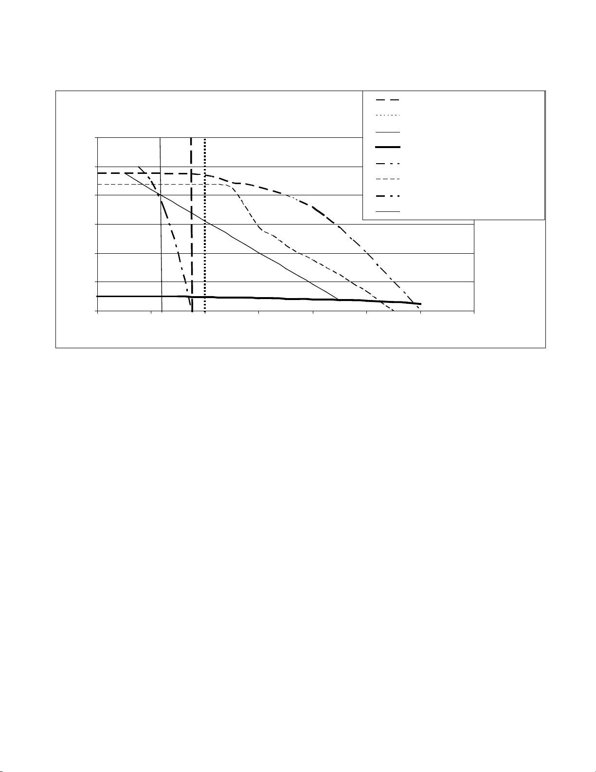
Pump Performance
1.5 HP Pumps
0
20
40
60
80
100
120
0
2 4 6
8
10 12 14
GPM
PSI
P4 3.5 GPM Positive Dis plac ement
P6 4 GPM Positive Displac ement
P9 2.33 GPM Positive Dis plac ement
M5 Mag Drive Centrifugal
T2 1/3 HP Turbine
T5-T6-T7-T8 3/4 HP Turbine
T9-TE 1 HP Turbine
S1 Speck Pump 7.5 GPM
S1
1 HP
3/4 HP
T2
M5
P9 P4 P6
Specifications subject to change without notice.
110-392 31
Page 34

RS-232 / RS-485 Communications
Serial Connector — A 9-pin D-connector (optional) is provided on the back panel of the Chiller for RS232 / RS485
data communication. A serial cable that uses only the following pins should be used to connect the Chiller to the
computer:
RS-232 RS-485
Pin # 2 data read (data from computer) Pin # 3 DAT (+) on “B”
Pin # 3 data transmit (data to computer) Pin # 5 signal ground
Pin # 5 signal ground Pin # 9 DAT (-) on “A”
RS-232 / RS-485 Protocol — The controller uses the following RS-232 / RS-485 protocol:
Data bits — 8
Parity — none
Stop bits — 1
Flow control — none
Baud rate — selectable (Chiller and PC baud rates must match).
Communications Commands — Commands must be entered in the exact format shown. Do not send a [LF] (line
feed) after the [CR] (carriage return). Be sure to follow character case exactly. A question mark (?) indicates that
the Chiller could not execute the command (either because it was in an improper format or the values were
outside the allowable range). A response followed by an exclamation point (!) indicates that a command was
executed correctly. A response must be received from the Chiller before another command can be sent. All
responses are terminated with a single [CR].
Command Description
Set command echo SEi[CR]
Set On / Off SOi[CR]
Set set point SSxxx[CR] x = ASCII digit ![CR]
Read set point temperature RS[CR] ![CR]
Read temperature RT[CR] ![CR]
Read temperature units RU[CR] C or F C[CR] or F[CR]
Read status RW[CR]
Read pressure in PSI RP[CR] ![CR]
Read pressure in kPa RK[CR] ![CR]
Read flow in GPM RG[CR] ![CR]
Read flow in LPM RL[CR] ![CR]
Read remote control voltage RC[CR] ![CR]
Read remote temperature probe RR[CR] ![CR]
Read ambient temperature on PCB RA[CR] ![CR]
Read fault status RF[CR] ![CR]
Read line voltage RV[CR] ![CR]
Read internal temperature R1[CR] ![CR]
Read external temperature R2[CR] ![CR]
Command
Format
Values Return Message
Echo: i = 1
No Echo: i = 0
On: i = 1
Off: i = 0
1 = Run
0 = Standby
![CR]
![CR]
1[CR] or 0[CR]
110-392 32
Page 35

Certificate of Compliance
Temperature Profile
0.00
5.00
10.00
15.00
20.00
25.00
30.00
35.00
40.00
0:00:00
0:04:04 0:08:09 0:12:40 0:16:45 0:20:50 0:24:55
0:29:00 0:33:0
Time (hh:mm:ss)
All Chillers are tested after assembly to ensure that the product meets or exceeds published mechanical and
safety specifications as well as your satisfaction. The Certificate of Compliance is included with the Chiller. The
following graph explains the steps involved in a typical test.
2
1
3 4
1. Raise fluid temperature.
2. Measure cooling performance.
3. Apply heat load to Chiller to simulate real application conditions. The heat load applied is based on the Chiller’s
cooling capacity.
4. Measure temperature stability.
Equipment Disposal (WEEE Directive)
or
This equipment is marked with the crossed out wheeled bin symbol to indicate it is covered by the Waste
Electrical and Electronic Equipment (WEEE) Directive and is not to be disposed of as unsorted municipal waste.
Any products marked with this symbol must be collected separately, according to the regulatory
guidelines in your area.
Service and Technical Support
If your unit fails to operate properly, contact the supplier from whom the unit was purchased. Have the model,
serial number, and voltage information from the back panel label along with a summary of the problem available.
110-392 33
Page 36

Replacement Parts
Description Part Number
Controller PCB
NOTE: When replacing the Controller PCB, it is important to note the software version. You
can obtain the software version by pressing and holding the Power Button on the controller
while the unit is in “Standby”. For our standard software the left display will read “T3” and the
right display will read “003” or software version T3-003. If you are unable to obtain the
software version, your model number and serial number will be required.
RTD Temperature Sensor 200-430
Remote / Ambient Tracking Probe, 10’ cable, DB9 Female Plug 060101
Remote / Ambient Tracking Probe, 25’ cable, DB9 Female Plug 060105
Remote / Ambient Tracking Probe, 50’ cable, DB9 Female Plug 060110
Fluid Pressure Sensor, Standard 750-381
Fluid Pressure Sensor, SS, DI units 750-384
Switch, Circuit Breaker, 30 Amp, 1PH 215-818
Flow Sensor, Hall Effect, Honeywell 330-087
Float Switch, Water Level, Single Float @ 7.0” 235-061
Float Switch, Water Level, Dual Float, @ 6.8/8.0” 235-064
Varies with software
options
Float Switch, Water level, Dual Float, @ 4.6/9.3” (NC contacts) 235-055
Compressor,1.5HP,COP #CS18K6E-PFV-255 750-876
Compressor, 2.0HP,COP #CS18K6E-PFJ-255 750-877
Compressor, 2.0HP,COP#CS18K6E-TFD-255 750-878
Compressor, 1.5HP, COP #CS18K6E-TF5-255 750-883
Motor, Fan, 230V, Emerson # 050-0265-00 215-519
Motor, Fan, 380-460V, Emerson # 950-0265-01 215-629
Heater Cartridge, 240V, 1000W (6xxx units) 215-459
Heater Cartridge, 240V, 1000W (5xxx untis) 215-903
Heater Cartridge, 240V, 2500W 215-564
Heater Cartridge, 480V, 1000W 215-654
Heater Cartridge, 480V, 3000W 215-644
Solid State Relay, 50 Amp, Crydom HA6050-10 (for Heaters) 200-343
Solid State Relay, 25 Amp, 48-600V, 3-32CV (Compressor) 200-580
Contactor, ABB A9-30-10-36 215-468
Contactor, ABB A26-30-10-36 215-674
Contactor, ABB DP60C2P-2 215-802
Capacitor, Start, Compressor, 145-174MFD, 250V, COP#914-000-607 750-336
Capacitor, Run, Compressor, 35MFD,370V, COP#914-0037-11 (60HZ) 750-337
Capacitor, Run, Compressor, 45MFD,370V, COP#914-0037-18 (50HZ) 750-414
110-392 34
Page 37

Description
106
280
218
Part Number
Relay, Compressor, COP#040-0166-15, COP#040-0166-15 750-338
PCB, 4-20mA Set Point Control 500-342
High Pressure Control, Penn#P100CC-9C, 275/175 215-473
Compressor Pressure Regulator Valve, SP#CRO-T-6-30/110-5/8ODF 750-766
Valve, Solenoid, Refrigeration, Liquid and Hot Gas Bypass, PK#DS1100,240VAC 750-179
Filter Dryer, SP#C-053-S, 3/8ODF 750-075
Air Filter, Condenser 750-387
Operator’s Manual 110-392
Pumps
Description Part Number
P4 – Positive Displacement, Rotary Vane, Bronze, 3.5 GPM, 240V/1PH/50-60HZ
P6 – Positive Displacement, Rotary Vane, Stainless Steel 4 GPM, 240V/1PH/50-60HZ
P9 – Positive Displacement, Rotary Vane, Bronze, 2.33 GPM,240V/1PH/50-60HZ
M5 – Mag-Drive Centrifugal Pump, 240V/1PH/50-60HZ (6xxx) 525-552
M6 – Mag-Drive Centrifugal Pump, 240V/1PH/50-60Hz (5xxx) 525-332
S1 – Speck Centrifugal, Stainless Steel, 7.5 GPM, 240V/1PH/50-60HZ 215-306
S3 – Speck Centrifugal, Stainless Steel, 7.5 GPM, 240V/480V/3PH/50-60Hz 215-884
T2 – 1/3HP Turbine, Bronze 3.5 GPM, 240V/1PH/50-60HZ 215-305
T5 – 3/4HP Turbine, Bronze, 240V/1PH/50-60HZ 215-499
T6 – 3/4HP Turbine, Stainless Steel, 240V/1PH/50-60HZ 215-474
T7 – 3/4HP Turbine, Stainless Steel, 208-230V/3PH/50-60HZ 215-475
T8 – 3/4HP Turbine, Bronze, 208-230V/3PH/50-60HZ 215-487
T9 – 1HP Turbine, Stainless Steel, 208-230V/3PH/50-60HZ 215-568
TD – 1HP Turbine, Bronze, 208-230V/3PH/50-60HZ 215-651
TE – 1HP Turbine, Bronze, 240V/1PH/50-60HZ 215-655
TF – 1HP Turbine, Bronze, 380/3/60Hz 215-873
TH – 2HP Turbine, Bronze, 208/230/1/60Hz 215-336
Pump – 215Motor – 215-217
Pump – 215Motor – 215-217
Pump – 215Motor – 215-217
Pump assemblies include motor unless listed separately.
110-392 35
Page 38

Warranty
NOTE: The warranty applies only to the original end user and cannot be transferred or sold to another end
user without written consent from the manufacturer.
The manufacturer’s warranty is one year for parts and labor and two years for parts. Please contact your supplier
for additional warranty details and service contract information.
The manufacturer agrees to correct for the original user of this product, either by repair, or at the manufacturer's
election, by replacement, any defect that develops after delivery of this product for the warranty period(s) stated
above. In the event of replacement, the replacement unit will be warranted for 90 days or warranted for the
remainder of the original unit’s parts or labor warranty period, whichever is longer. If a replacement unit is sent,
the defective unit must be returned to the manufacturer within 30 days of receipt of the replacement unit. If the
defective unit is not received within 30 days, the manufacturer reserves the right to bill for the replacement unit.
If this product requires service, contact the manufacturer/supplier's office for instructions. If return of the product is
necessary, a return authorization number will be assigned and the product should be shipped, (transportation
charges pre-paid), to the indicated service center. To insure prompt handling, the return authorization number
should be placed on the outside of the package and a detailed explanation of the defect enclosed with the item.
This warranty shall not apply if the defect or malfunction was caused by accident, neglect, unreasonable use,
improper service, or other causes not arising out of defects in material or workmanship. There are no warranties,
expressed or implied, including, but not limited to, those of merchantability or fitness for a particular purpose
which extends beyond the description and period set forth herein.
The manufacturer's sole obligation under this warranty is limited to the repair or replacement of a defective
product and shall not, in any event, be liable for any incidental or consequential damages of any kind resulting
from use or possession of this product. Some states do not allow: (A) limitations on how long an implied warranty
lasts; or (B) the exclusion or limitation of incidental or consequential damages, so the above limitations or
exclusions may not apply to you. This warranty gives you specific legal rights. You may have other rights that vary
from state to state.
110-392 36
Page 39

Appendix
Flow Schematic - All Models
110-392 37
Page 40

Electrical Diagram – 208-230V / 1PH / 50-60Hz Models without heater option
110-392 38
Page 41

Electrical Diagram – 208-230V / 1PH / 50-60Hz Models with heater option
110-392 39
Page 42

Electrical Diagram – 208-230V and 380-460V / 3PH / 50-60Hz Models without heater option
110-392 40
Page 43

Electrical Diagram – 208-230V and 380-460V / 3PH / 50-60Hz Models with heater option
110-392 41
Page 44

Options
General Options Wiring
Status Alarm (STA): Relay is energized when Chiller is running normally. Relay is de-energized when a fault condition
is detected or the unit is placed in Standby.
Remote ON/OFF: RCV = Chiller turns OFF when 12-24V AC or DC signal is applied.
RCS = Chillers turns OFF when contacts are closed.
RS-485 Communications Wiring
110-392 42
Page 45
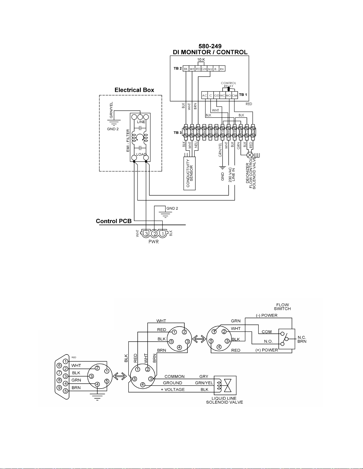
DI Control Wiring
H2 & H3 Option Wiring
H2 = 24 VDC
H3 = 12 VDC
110-392 43
Page 46

4-20 mA Set Point Control
Manufactured by:
This feature is optional and may not appear in your version of the software.
NOTE: Two versions are available. If the model number of your Chiller contains an N in the 11
digit (e.g., 6860T56A26ND), it provides 4-20mA set point control over a temperature range of 5° to
90°C; if the 11th digit is an K, the 4-20mA control range is 4° to 40°C
Go to menu item “CC” and set to “YES”.
If current input is outside of the range of the 4–20 mA, “Ft 18” will be displayed.
th
PolyScience
6600 W. Touhy Avenue Niles, IL 60714 U.S.A.
1-800-229-7569 ● 1-847-647-0611
www.polyscience.com
 Loading...