

Page 1
Installation Quickstart
Schnelleinstieg
Guía de instalación rápida
Guide de démarrage rapide
Guida rapida
Page 2

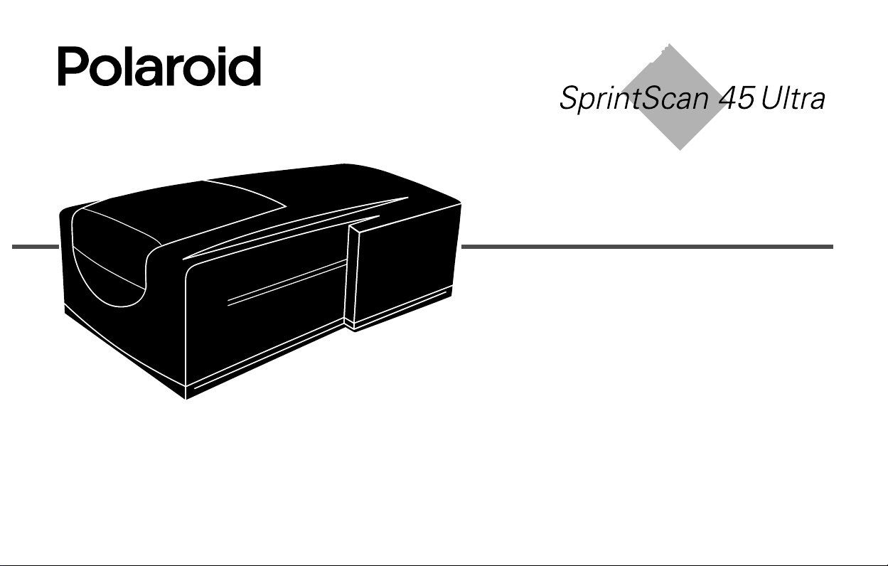
SprintScan 45 Ultra
English . . . . . . . . . . . . . . . . . . . . . 3
Deutsch . . . . . . . . . . . . . . . . . . . 19
Español. . . . . . . . . . . . . . . . . . . . 35
Français . . . . . . . . . . . . . . . . . . . 51
Italiano . . . . . . . . . . . . . . . . . . . . 67
Page 3

English 3
System Requirements
Macintosh Systems
• A Power Macintosh computer (includes Power Macintosh
G3 and G4 computers) or compatible with a PowerPC
processor and 64 megabytes (MB) of RAM.
• Apple system software version 7.6 or later.
• 400 MB of free disk space.
• Scratch disk space equal to twice the final image file size
plus 4 MB.
• A video adapter and monitor capable of displaying
thousands of colors, minimum. 24-bit color (16.7 million
colors) is recommended for optimal display of scanned
pictures.
PC Systems
• An IBM PC computer or compatible with at least a 300-MHz
Pentium processor and 128 megabytes (MB) of RAM.
(RAM equal to the typical image file size is recommended.)
• Microsoft Windows 95, 98 or NT (version 4 or later)
operating system.
• 400 MB of free disk space.
• An ASPI-compliant SCSI adapter with the appropriate
Windows 95, 98 or NT drivers.
• A video adapter and monitor capable of displaying
thousands of colors, minimum. 24-bit color (16.7 million
colors) is recommended for optimal display of scanned
pictures.
Page 4
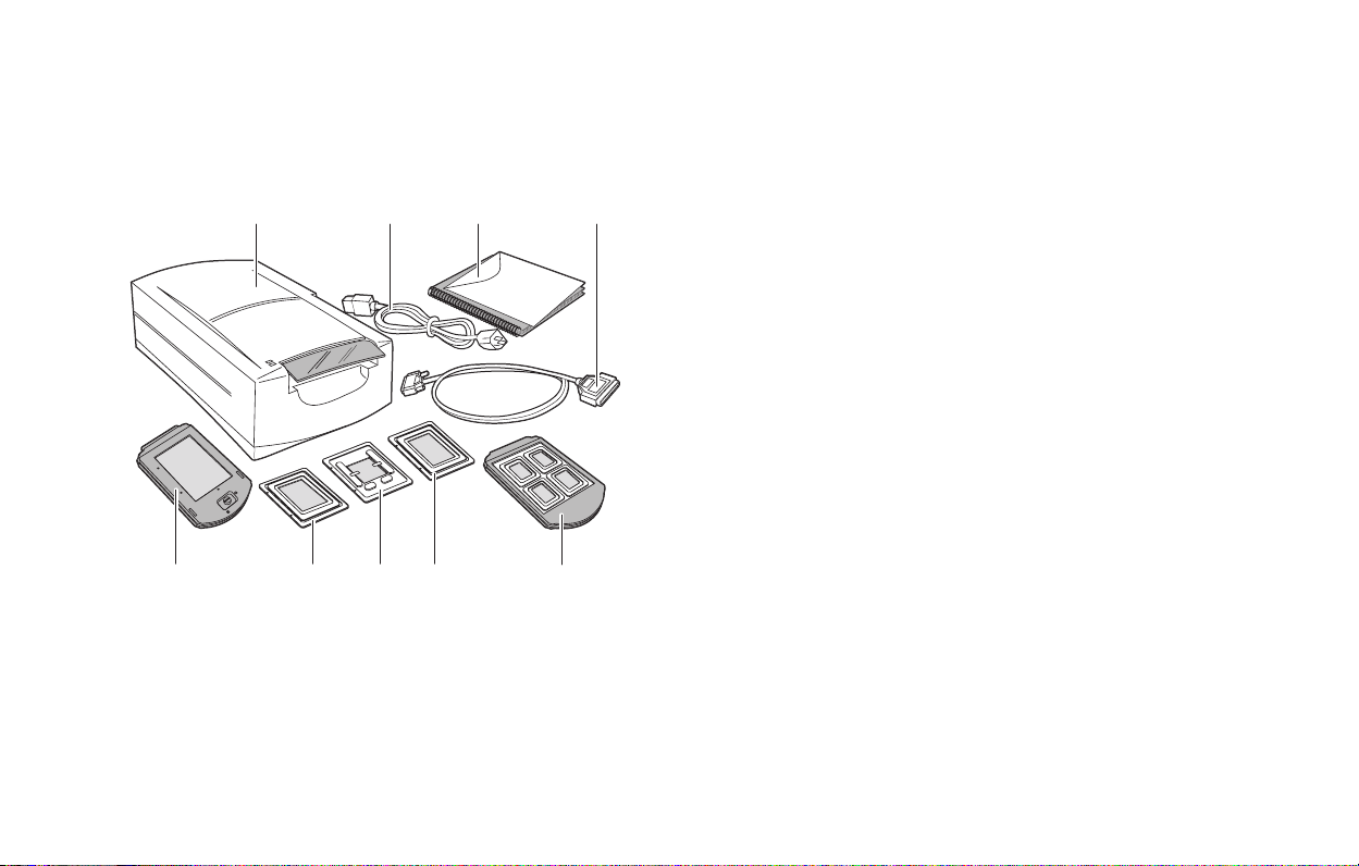
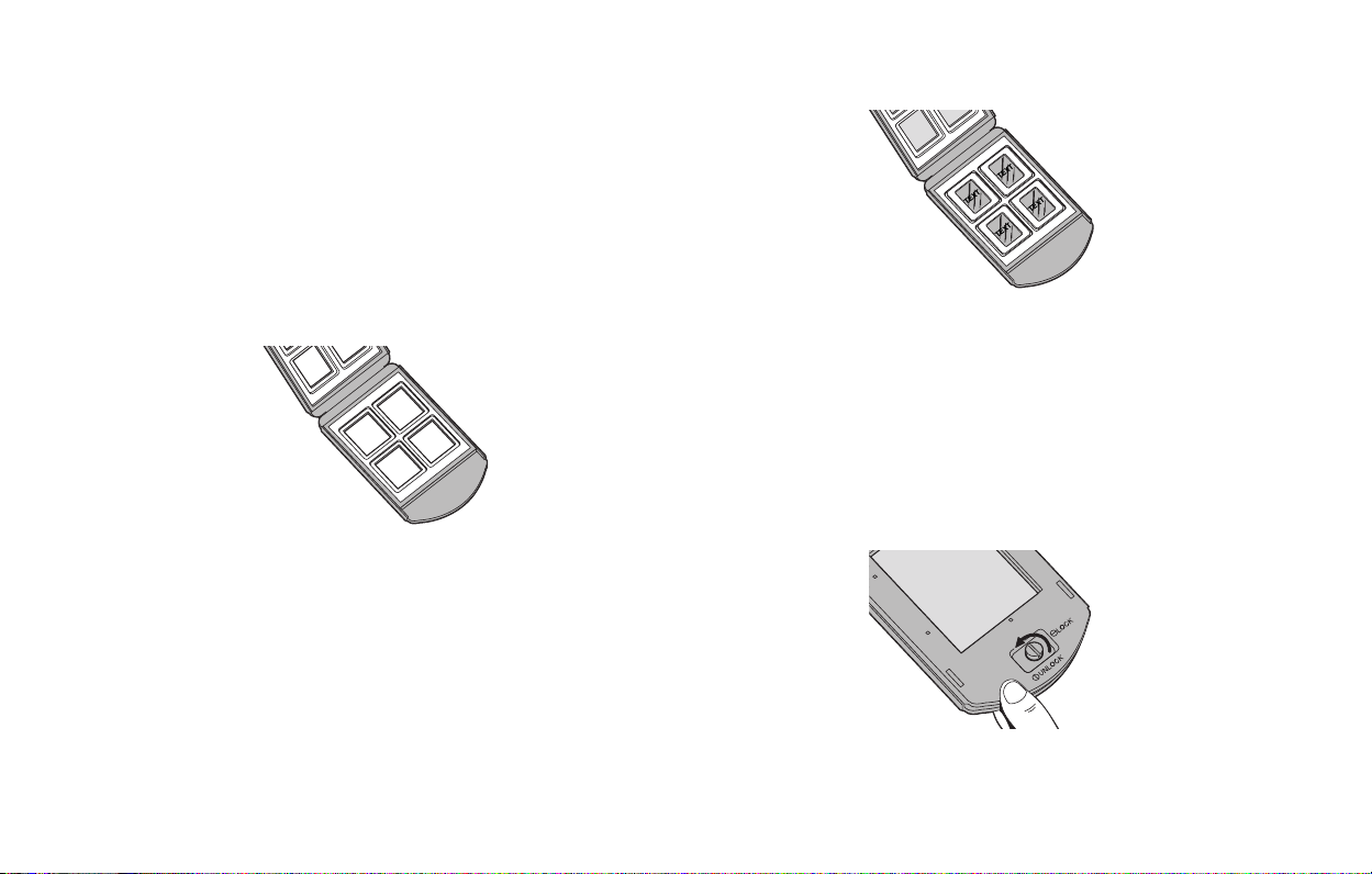
1 Unpack the Box
Make sure you have all the following components. Contact your
dealer if any is missing or damaged.
abcd
Adapter for 120 film, 2 1/4 x 2 1/4 in.
f
g
Adapter for single 35mm slide
Adapter for 120 film, 2 1/4 x 2 3/4 in.
h
i
Four-slide film carrier
j
35mm slide spacer (not shown)
Two magnets for 120 film (not shown)
k
l
The PolaColor Insight Software CD (not shown) containing:
• PolaColor Insight software for Windows 95, 98, and NT
• PolaColor Insight software for Power MAC and
PowerPC systems and an Adobe Photoshop plug-in
• Online user’s guide
efg
a
Scanner
Power cable (several provided for various power sources)
b
c
This manual
d
SCSI cable (25-pin to 50-pin)
Film carrier for 4x5 film
e
hi
Warning:
Nothing inside the scanner is user serviceable.
Do not disassemble the scanner. Doing so could result
in severe electrical shock and damage to the scanner.
This action may also void your warranty. Contact
Polaroid Technical Support or your dealer if the
scanner is malfunctioning. (To contact Polaroid from
within the U.S.A., call
U.S.A., see
guide or visit
Getting assistance
www.polaroid.com
1-800-432-5355
in the online user’s
on the World
. Outside the
Wide Web.)
English 4
Page 5

English 5
2 Position the Scanner
Place the scanner on a flat, stable surface, free of vibration. Leave
at least 2 inches (50mm) of space around all sides and the top of
the scanner for adequate ventilation, and leave room at the back
to reach the power switch on the rear panel.
Caution:
As with any highly sensitive optical equipment, vibrations or bumping the scanner during use may result in
picture defects. Locate the unit where it will not be disturbed during use.
3 Install the Software
Turn the computer on.
1
Close any applications that may be running.
2
3
Insert the Polaroid PolaColor Insight CD into the drive.
Power Mac or PowerPC Windows 95, 98 or NT
Select Polaroid
1
PolaColor Insight
Installer.
2
Follow the instruc-
tions on the screen.
3
If you want to install
the Photoshop plug-in,
double-click the Plug
In Installer in the
PolaColor Insight
folder and follow the
instructions on the
screen.
Remove the CD from the drive.
4
Wait for the install
1
program to start.
If it does not, select
Run from the Start
menu. Click Browse
and select
SETUP.EXE on the
CD-ROM. Click OK.
2
Follow the instructions on the screen.
Page 6

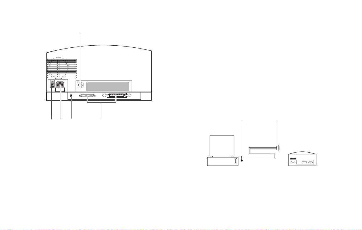
4 Connect the Scanner to
the Computer
The SprintScan 45 Ultra requires a SCSI host adapter in your
computer. If your computer does not have an adapter, you must
install one (see page 17). If your computer is a PC-compatible
with a SCSI adapter, but the adapter is connected to a hard drive
or CD-ROM drive, installing a second adapter is recommended.
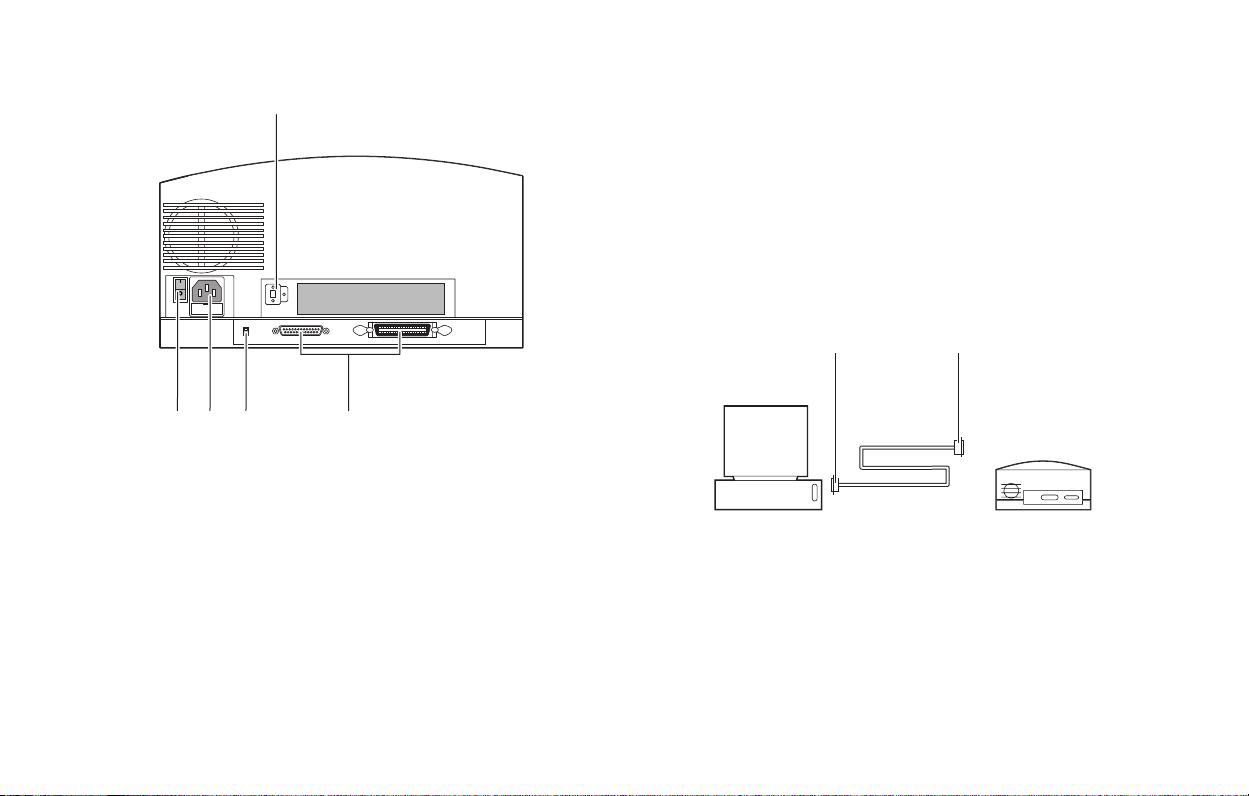
Set the Scanner SCSI Address
Each device connected to a SCSI host adapter must have a unique
address from 0-6. To assure a unique address for the scanner,
determine the addresses of any other SCSI devices.
Power Mac or PowerPC Windows 95, 98 or NT
1
Run the Apple System
Profiler program, usually
on the Apple menu. If not,
it may be available from
www.apple.com/
swupdates.
Click Devices and
2
Volumes to view the SCSI
device addresses.
Make sure the scanner is turned off and set the address switch
(b on page 7) to a value not used by any other device.
Note:
The address is preset to 4. Do not change it unless another
device is using 4. Other addresses typically available are 2,
5, and 6.
Look at the address switch
on each SCSI device
connected to your system. If
necessary, see the
instructions provided with
the devices.
English 6
Page 7
English 7
bc d e
SCSI address switch
a
b
Power switch
Power connector
c
a
Place the scanner at the end of the SCSI chain or between the
computer and other SCSI devices as shown in the following
diagrams. Use the shortest possible cables.
Connect the SCSI Cables
Note:
Turn the computer, scanner and all other SCSI devices off
before connecting or disconnecting any cables. Do not
connect the scanner to the parallel connector on your
computer. Doing so could damage the scanner or
computer.
50 pins
Scanner
(termination on)
SCSI termination switch
d
e
SCSI connectors (25, 50)
25 pins
Computer
Page 8
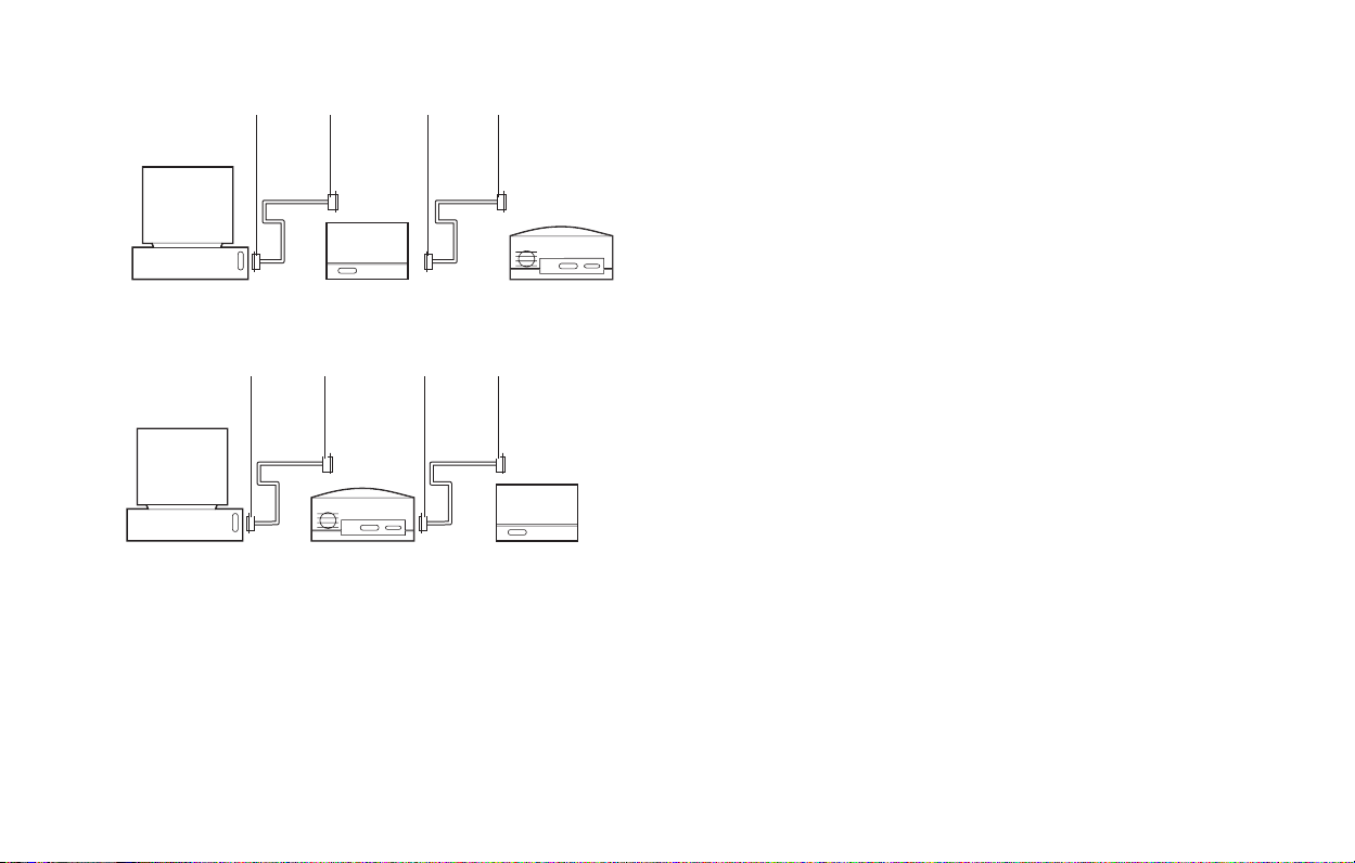
25
pins
50
pins
25
pins50pins
You may need additional cables or adapters to connect the
scanner. Your cable must have a 50-pin Centronics M or DB-25
M connector at one end for attachment to the scanner, and the
cable should be as short as possible. To determine the connector
you need for attachment to your SCSI adapter, refer to
instructions with the adapter.
Computer
pins50pins
Computer
Other SCSI device
(unterminated)
25
(termination off)
pins50pins
Scanner
(termination on)
25
Other SCSI device
(terminated)
Scanner
Set Termination
Terminate the scanner and all other SCSI devices as shown in the
appropriate cabling diagram to the left or on page 7. The last
device in the SCSI chain must be terminated (or termination on),
while all other devices must be unterminated (or termination off).
Set scanner termination with the termination switch (d on
page 7). On = terminated, Off = unterminated.
Termination instructions for your other SCSI devices are
provided with the devices.
English 8
Page 9

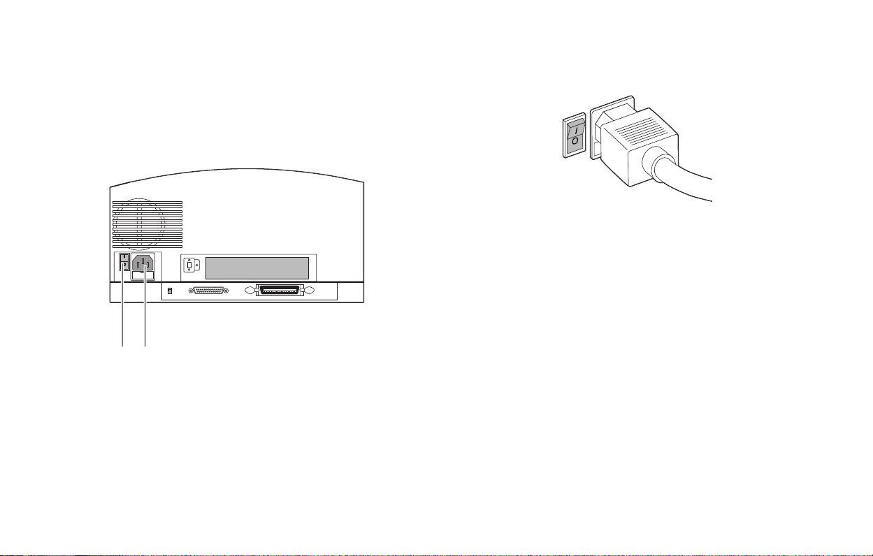
5 Connect the Scanner to
AC Power and Turn On
1
Connect the power cord to the power connector (b).
ab
English 9
Turn the scanner power switch on.
2
3
Check the lights. The green light indicates power on. The
yellow light blinks while the scanner initializes, and it
remains steady when the scanner is ready. (The yellow light
also blinks during scanning.)
4
Turn the computer on.
Wait for the system to install the scanner driver and display
5
the normal desktop.
a
Power switch
b
Power connector
Page 10
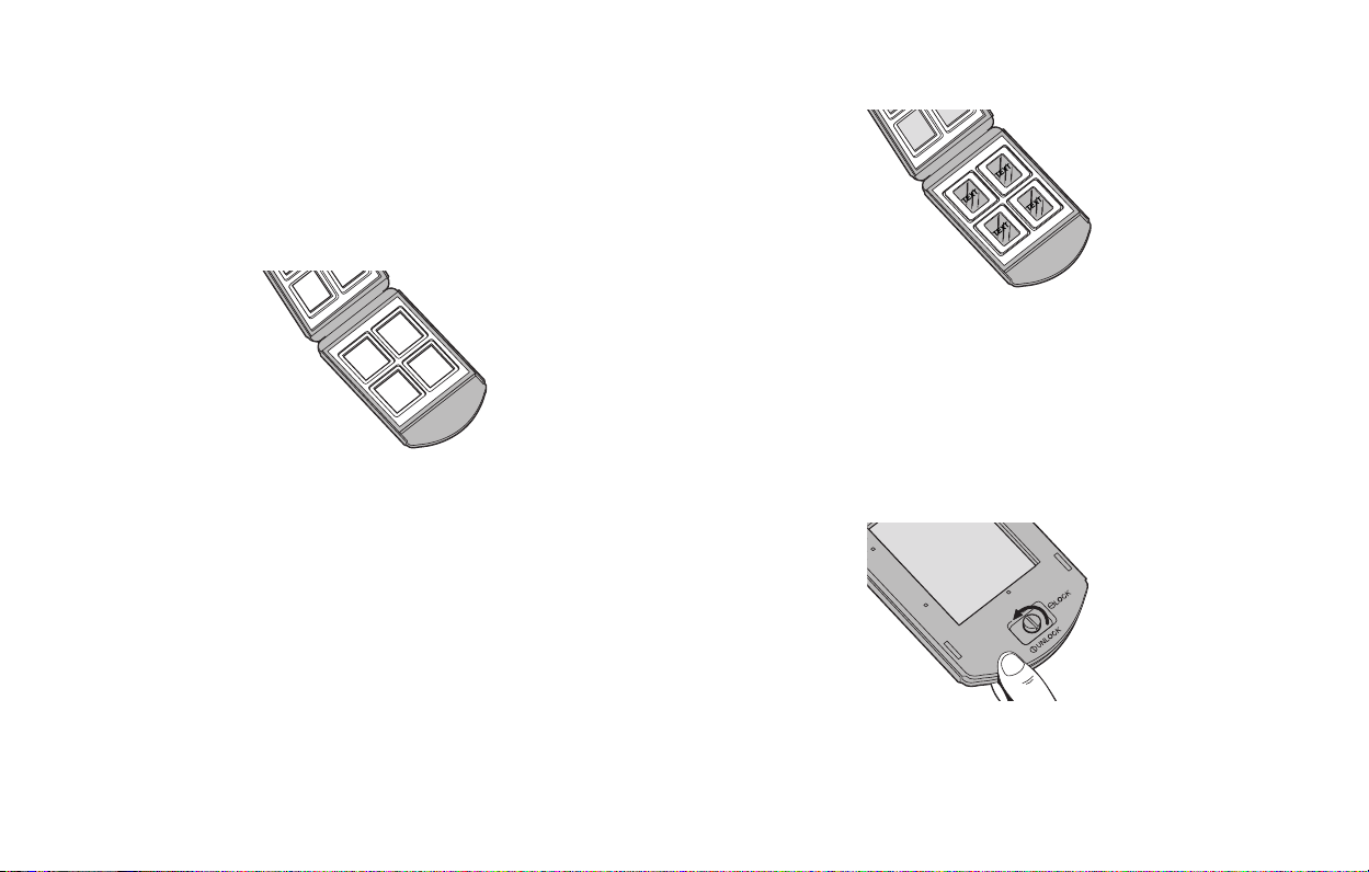
6 Loading the Film Carriers
The Four-Slide Film Carrier
With the text facing up and the hinge at the top, open the
1
carrier flat as shown.
Place up to four mounted 35mm slides in the spaces pro-
2
vided. Be sure the slide mounts fit properly in the recessed
areas. The images should be right-side up and right-reading
as you do so. The emulsion side will face down.
3
Close the carrier carefully.
The 4x5 Carrier (for 4x5 film)
To unlock the carrier, squeeze the two halves of the carrier
1
together at the bottom edge (near the locking knob) with one
hand while turning the locking knob in either direction, until
the slot in the knob points to UNLOCK.
English 10
Page 11
2
Open the carrier flat. Insert a 4x5 chrome or negative so that
the left edge is against the positioning pins. Position the film
so the image is right-reading and right-side up (emulsionside down).
The emulsion side is the dull side.
Note:
Pins
3
Close the carrier. Squeeze the carrier at the bottom edge and
turn the knob to lock it.
English 11
The 120 Film Adapters
(for 2 1/4 x 21/4 and 2 1/4 x 2 3/4 in. film)
Open the 4x5 carrier as described previously.
1
Locate the appropriate adapter for your image. One is
2
designed for 2 1/4 x 2 3/4 in. images, and one is for 2 1/4 x
2π in. square images.
Note:
The frame of film must be cut from the film strip in
order to be scanned.
3
Orient the adapter so that the words THIS SIDE UP (on the
adapter) face up, and the notches are at the left edge. Place
the unmounted film over the opening, within the raised
ridges of the adapter. Position the film so the image is rightreading and right-side up.
3
Page 12
Secure the film with the two magnets provided, on the top
4
and bottom edges. Be sure the magnets are also within the
raised ridges.
Place the adapter in the 4x5 carrier, sliding the notches into
5
the pins on the left edge. The film and magnets should be
face up, as shown.
Close the carrier. Squeeze the carrier at the bottom edge and
6
turn the knob to lock it.
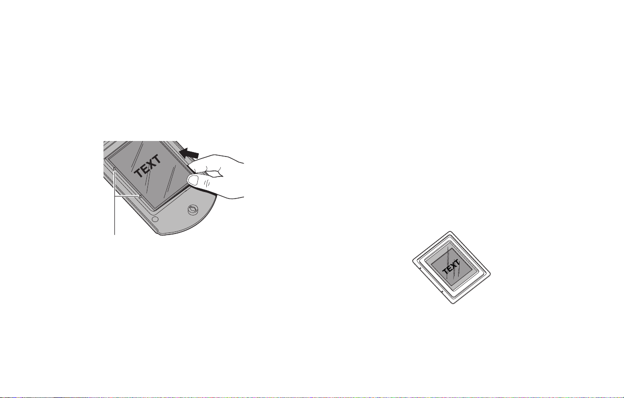
The Single-35mm Carrier
1
Open the 4x5 carrier as described previously.
Locate the single-35mm adapter.
2
Note:
You can use a negative, or a mounted or unmounted
slide.
Orient the adapter so the metal tabs face up, and the notches
3
are at the left edge. Slide the film into the channel, under the
two metal tabs. Position the film so the image is rightreading and right-side up.
English 12
Page 13
4
If the film is unmounted or the mount is thin, use the slide
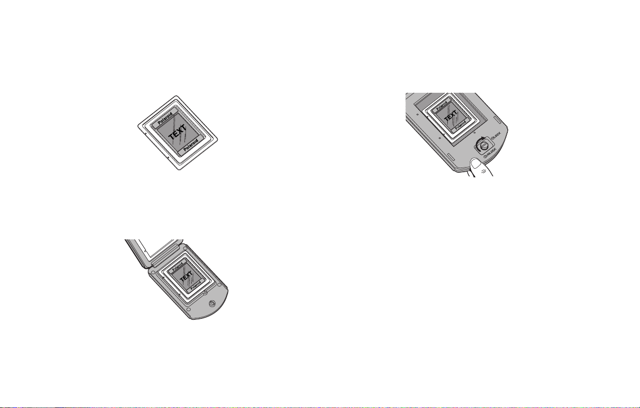
spacer provided. Position the slide spacer on top of the slide.
The film should fit snugly into the adapter. (The spacer also
ensures that the image will be at the correct distance from the
scanning mechanism.)
TEXT
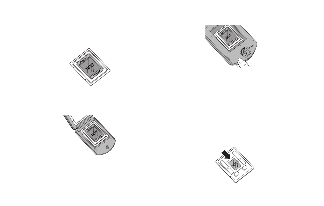
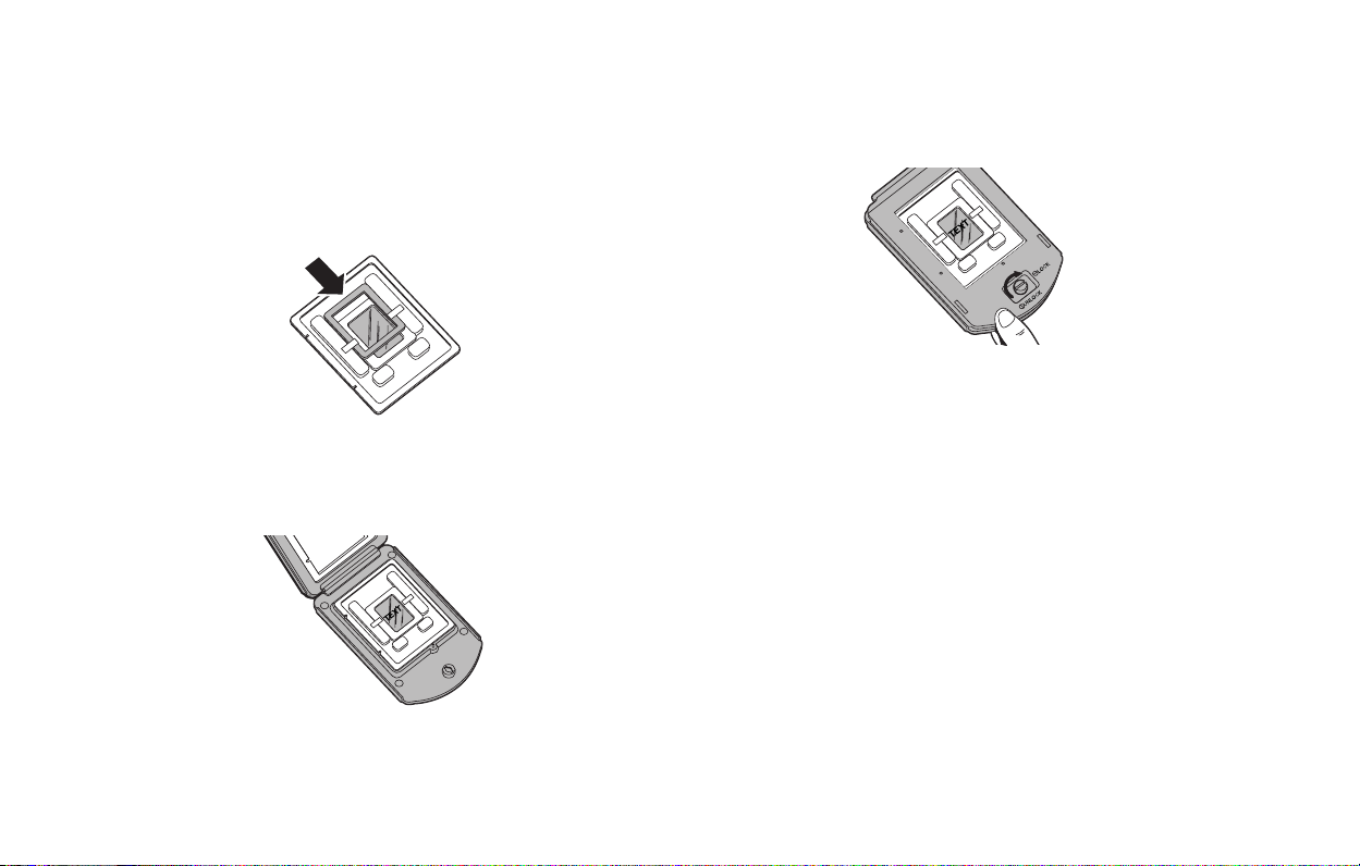
Place the adapter in the 4x5 carrier, sliding the notches into
5
the pins on the left edge. The slide and tabs should be facing
up.
English 13
Close the carrier. Squeeze the carrier at the bottom edge and
6
turn the knob to lock it.
Page 14
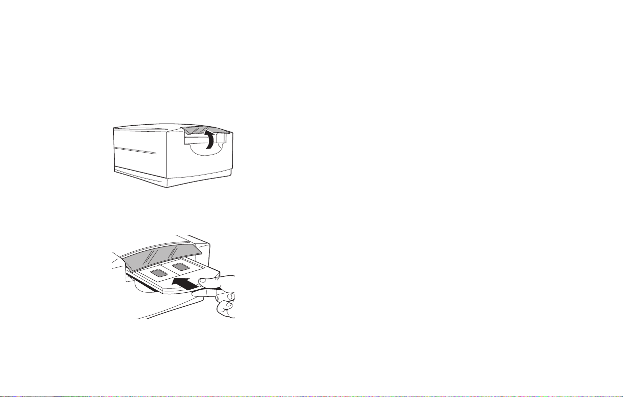
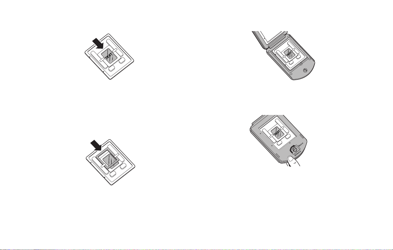
7 Insert the Carrier into the
Scanner
1
Open the carrier access door.
Insert the carrier gently and firmly into the carrier slot as
2
shown, until you feel it stop.
Close the carrier access door. The scanner will not scan if the
3
door is open.
Note:
4
Initiate the scan from your software. The software will
prompt you when the scan is finished.
Do not open the carrier access door while a scan is in
process; the scan will be interrupted. The scan will
resume when the door is closed, but the quality of the
scan may be reduced. Scan again with the door
closed for best scanning quality.
English 14
Page 15

8 Preview an Image
Load the film or slide into the film carrier (as described
1
previously).
2
Insert the carrier into the scanner (as described previously).
Start the PolaColor Insight program:
3
Power Mac or PowerPC Windows 95, 98 or NT
Double-click PolaColor
Insight.
To start the Photoshop
plug-in within another
application, select Import
from the application’s
File menu and select
PolaColor Insight.
Select Programs from
1
the Start menu.
2
Point to Polaroid PolaColor Insight, then
select PolaColor
Insight.
English 15
Select the type of slide or negative you are scanning from the
4
Input list on the Preview panel.
Select your monitor type from the Display list.
5
Type or select the number of the carrier frame you want to
6
scan in the Frame Number box.
Click Preview.
7
The image appears on the Preview panel.
Page 16

9 Enhance and Scan the
10 Remove the Carrier
Image
Follow the online user’s guide instructions to enhance the image
and perform a final scan.
To view the online
Power Mac or PowerPC Windows 95, 98 or NT
Double-click PolaColor
1
Insight, launching the
PolaColor Insight
program.
Select PolaColor Insight
2
Help from the Help
menu.
PolaColor Insight User’s Guide
Select Programs from
1
the Windows Start
menu.
2
Point to Polaroid PolaColor Insight and select
User's Guide
.
:
When the scan is complete, open the door and remove the
1
carrier. Remove the film and store it properly to protect it
from dust and fingerprints.
2
Close the carrier access door. The door should be kept closed
at all times to protect the mechanism from dust.
English 16
Page 17

English 17
Installing a SCSI Host Adapter
The SprintScan 45 Ultra connects to a SCSI host adapter in your
computer. Most Macintosh computers have a SCSI adapter built
in, but most IBM PC compatible computers do not.
If you must install a SCSI adapter, turn the computer off and
follow instructions provided by the adapter manufacturer. (The
procedure usually includes software installation. If your PC uses
the Windows NT operating system, log in as an administrator
before installation.)
Limited Warranty
Polaroid Corporation warrants the SprintScan 45 Ultra scanner
against defects in manufacture or workmanship for a period of
one year from the date of purchase. To verify the warranty period,
you should keep the invoice, sales receipt, or other proof of the
purchase date.
Should this product or any component or accessory included with
it, with the exception of software, prove to be defective at any
time during the warranty period, Polaroid Corporation will, at its
discretion, either replace or repair this item, without charge.
This warranty does not cover damage caused by accident,
incorrect installation, unauthorized modification, and misuse or
abuse. A charge will be made for repair of such damage.
This warranty excludes all consequential damages. Some
jurisdictions do not allow the exclusion or limitation of
consequential damages, so the foregoing exclusion may not
apply to you.
Page 18

Radio and Television
Interference
FCC Notice (U.S.A.)
Note:
This equipment has been tested and found to comply with
the limits for a Class B digital device, pursuant to Part 15
of the FCC Rules. These limits are designed to provide
reasonable protection against harmful interference in a
residential installation. This equipment generates, uses,
and can radiate radio frequency energy and, if not
installed and used in accordance with the instructions,
may cause harmful interference to radio communications.
However, there is no guarantee that interference will not
occur in a particular installation. If this equipment does
cause harmful interference to radio or television
reception, which can be determined by turning the
equipment off and on, the user is encouraged to try to
correct the interference by one or more of the following
measures:
• Reorient/relocate the receiving antenna.
• Increase the separation between the equipment and receiver.
• Connect the equipment into an outlet on a circuit different
from that to which the receiver is connected.
• Consult the dealer or an experienced radio/TV technician for
help.
Note:
A shielded interface cable with a ferrite core installed on
the scanner connector end must be used with this
equipment.
FCC Caution:
To assure continued compliance, any changes or
modifications not expressly approved by the party responsible
for compliance could void the user’s authority to operate the
equipment.
Product: The Polaroid SprintScan 45 Ultra Scanner
Marketed by: Polaroid Corporation, Cambridge, MA 02139
U.S.A. Telephone:
1-800-432-5355
This device complies with Part 15 of the FCC Rules. Operation is
subject to the following two considerations: (1) This device may
not cause harmful interference, and (2) this device must accept
any interference received, including interference that may cause
undesired operation.
© 2000 Polaroid Corporation, Cambridge,
“Polaroid”, “SprintScan”, and “PolaColor” are trademarks of Polaroid
Corporation.
owners.
All other product names may be trademarks of their respective
111705B (PW–91396M-1)
MA 02139, U.S.A.
All rights reserved.
English 18
Page 19

Deutsch 19
Systemanforderungen
Macintosh-Systeme
• Power Macintosh (Power Macintosh G3 oder G4) oder
kompatibler Computer mit PowerPC-Prozessor und 64 MB
RAM.
• Apple-Systemsoftware ab Version 7.6.
• 400 MB freier Festplattenspeicher.
• temporärer Plattenspeicher, der der zweifachen
Bilddateigröße plus 4 MB entspricht.
• Grafikkarte und Monitor für mindestens 16 Bit Farbtiefe. Für
eine optimale Anzeige der gescannten Bilder empfiehlt sich
eine Farbtiefe von 24 Bit (16,7 Mio. Farben).
PC-Systeme
• IBM-kompatibler PC mit Pentium-Prozessor (mindestens
300 MHz) und 128 MB RAM. (Der RAM sollte nach
Möglichkeit der normalen Bilddateigröße entsprechen.)
• Betriebssystem Microsoft Windows 95, 98 oder NT
(ab Version 4).
• 400 MB freier Festplattenspeicher.
• ASPI-kompatibler SCSI-Adapter mit den entsprechenden
Windows 95-, 98- oder NT-Treibern.
• Grafikkarte und Monitor für mindestens 16 Bit Farbtiefe. Für
eine optimale Anzeige der gescannten Bilder empfiehlt sich
eine Farbtiefe von 24 Bit (16,7 Mio. Farben).
Page 20
1 Auspacken
Überprüfen Sie zunächst den Inhalt der Verpackung. Sollte eines
der nachfolgend genannten Teile fehlen oder beschädigt sein,
wenden Sie sich an Ihren Händler.
abcd
efg
a
Scanner
b
Netzkabel (für unterschiedliche Spannungsquellen stehen
verschiedene Netzkabel zur Verfügung)
das vorliegende Handbuch
c
d
SCSI-Kabel mit 25-poligem und 50-poligem Stecker
e
Filmstreifenhalter für 4x5-Planfilm
hi
Adapter für 120er Rollfilm, 6x6 cm
f
g
Adapter für KB-Einzeldia
h
Adapter für 120er Rollfilm, 6x7 cm
i
Filmstreifenhalter für 4 Dias
KB-Abstandshalter (ohne Abbildung)
j
zwei Magneten für 120er Rollfilm (ohne Abbildung)
k
l
PolaColor Insight-Software-CD (ohne Abbildung) mit:
• PolaColor Insight-Software für Windows 95, 98 und NT
• PolaColor Insight-Software für Power MAC- und
PowerPC-Systeme und einem Adobe Photoshop-Plugin
• Online-Benutzerhandbuch
Warnung:
Der Scanner enthält keine Komponenten, die durch
den Benutzer gewartet werden können. Nehmen Sie
den Scanner nicht auseinander, da dies gefährliche
elektrische Schläge und eine Beschädigung des
Scanners sowie einen Verfall Ihrer Garantieansprüche zur Folge haben könnte. Wenden Sie sich
bei Funktionsstörungen des Scanners an die technische Unterstützung von Polaroid bzw. an Ihren
Händler. (Innerhalb der USA können Sie Polaroid
unter der Rufnummer
1-800-432-5355
erreichen.
Kunden außerhalb der USA können die Kontaktrufnummern dem Abschnitt
Unterstützung
im Online-
Benutzerhandbuch oder der Polaroid-Website unter
www.polaroid.com
entnehmen.)
Deutsch 20
Page 21

Deutsch 21
2 Aufstellen des Scanners
Stellen Sie den Scanner auf eine ebene, vibrationsfreie und
stabile Unterlage. Um eine ausreichende Be- und Entlüftung zu
gewährleisten, sollten Sie auf allen Seiten und über dem Scanner
mindestens 50 mm Abstand frei lassen. Lassen Sie außerdem
etwas Platz auf der Rückseite, damit Sie den Netzschalter
bequem erreichen können.
Vorsicht:
Wie bei allen sensiblen optischen Geräten kann es zu
Bildfehlern kommen, wenn das Gerät während des
Betriebs Vibrationen oder Stößen ausgesetzt ist.
Stellen Sie das Gerät daher an einer Stelle auf, an der
der Betrieb nicht beeinträchtigt werden kann.
3 Installieren der Software
1
Schalten Sie den Computer ein.
Schließen Sie alle Anwendungen.
2
3
Legen Sie die Polaroid PolaColor Insight-CD in das
CD-ROM-Laufwerk ein.
Power Mac oder PowerPC Windows 95, 98 oder NT
Wählen Sie den Polaroid
1
PolaColor InsightAktualisierer.
2
Folgen Sie den
Anweisungen auf dem
Bildschirm.
3
Wenn Sie das PhotoshopPlugin installieren
möchten, doppelklicken
Sie im Ordner PolaColor
Insight auf den
entsprechenden
Aktualisierer, und folgen
Sie den Anweisungen auf
dem Bildschirm.
4
Nehmen Sie die CD aus dem Laufwerk.
Warten Sie, bis das
1
Installationsprogramm
automatisch gestartet
wird.
Sollte dies nicht
eintreten, wählen Sie aus
dem Menü Start den
Befehl Ausführen.
Klicken Sie auf die
Schaltfläche
Durchsuchen, und
wählen Sie auf der CDROM die Datei
SETUP.EXE. Klicken
Sie auf OK.
2
Folgen Sie den
Anweisungen auf dem
Bildschirm.
Page 22

4 Anschließen des Scanners
an den Computer
Zum Anschließen des SprintScan 45 Ultra-Scanners benötigen
Sie in Ihrem Computer einen SCSI-Hostadapter. Dieser muss
gegebenenfalls nachinstalliert werden (siehe Seite 33). Wenn es
sich bei Ihrem Computer um ein PC-kompatibles Gerät mit
SCSI-Adapter handelt, dessen Adapter an das Festplatten- oder
CD-ROM-Laufwerk angeschlossen ist, empfiehlt sich die
Installation eines zweiten Adapters.
Festlegen der SCSI-Adresse des Scanners
Jedem an einen SCSI-Hostadapter angeschlossenen Gerät muss
eine eindeutige Adresse im Bereich von 0 bis 6 zugeordnet
werden. Um Konflikte mit anderen Geräten auszuschließen,
sollten Sie zunächst die Adressen aller anderen SCSI-Geräte
ermitteln:
Power Mac oder PowerPC Windows 95, 98 oder NT
1
Führen Sie den Apple
System Profiler aus. In der
Regel finden Sie dieses
Programm im Apple-Menü.
Andernfalls können Sie das
Programm von
www.apple.com/swupdates
herunterladen.
2
Klicken Sie auf Geräte und
Volumes, um die Adressen
der SCSI-Geräte
anzuzeigen.
Prüfen Sie, ob der Scanner ausgeschaltet ist, und stellen Sie den
Adressenschalter (b auf Seite 23) auf einen Wert, der noch von
keinem anderen Gerät belegt ist.
Hinweis:
Standardmäßig ist die Adresse 4 voreingestellt.
Ändern Sie diesen Wert nur dann, wenn er bereits von
einem anderen Gerät belegt ist.
die Adressen 2, 5 und 6 verfügbar.
Überprüfen Sie an jedem
SCSI-Gerät, das an Ihr
System angeschlossen ist,
den SCSI-Adressenschalter.
Nähere Informationen
finden Sie gegebenenfalls in
den Unterlagen, die Sie mit
den entsprechenden Geräten
erhalten haben.
In der Regel sind auch
Deutsch 22
Page 23
Deutsch 23
bc d e
SCSI-Adressenschalter
a
Netzschalter
b
c
Netzanschluss
a
Schließen Sie den Scanner am Ende der SCSI-Kette oder
zwischen dem Computer und einem anderen SCSI-Gerät an.
(Siehe nachstehende Abbildung.) Verwenden Sie nach
Möglichkeit kurze Kabel.
Anschließen der SCSI-Kabel
Hinweis:
Vor dem Anschließen und Abziehen von Kabeln
sollten Sie den Computer, den Scanner und alle
anderen SCSI-Geräte grundsätzlich abschalten.
Verbinden Sie den Scanner auf keinen Fall mit dem
Parallelanschluss Ihres Computers, da dies zu einer
Beschädigung des Scanners bzw. Computers führen
kann.
25-polig
SCSI
d
50-polig
Terminierungsschalter
SCSI-Anschlüsse (25, 50)
e
Computer
Scanner
(terminiert)
Page 24

polig
Computer
polig
Computer
25-
25-
50-
polig
anderes SCSI-Gerät
(nicht terminiert)
50-
polig
(nicht terminiert)
polig
polig
Scanner
25-
25-
50-
polig
Scanner
(terminiert)
50-
polig
anderes SCSI-
Gerät
(terminiert)
Zum Anschließen des Scanners sind unter Umständen noch
weitere Kabel oder Adapter erforderlich. Scannerseitig muß Ihr
Kabel über einen 50-poligen Centronics M- oder DB-25
M-Stecker verfügen. Außerdem sollte es so kurz wie möglich
sein. Hinweise dazu, welchen Steckertyp Sie für Ihren SCSIAdapter benötigen, finden Sie in den Unterlagen, die Sie mit dem
Adapter erhalten haben.
Festlegen der Terminierung
Legen Sie die Terminierung des Scanners und aller anderen
SCSI-Geräte gemäß der entsprechenden Abbildung auf der
linken Seite oder auf Seite 23 fest. Das jeweils letzte Gerät in der
SCSI-Kette muss terminiert sein (d. h., die Terminierung ist
aktiviert). Bei allen anderen Geräten muss die Terminierung
deaktiviert sein.
Das Festlegen der Terminierung erfolgt mit dem
auf Seite 23).
Terminierungsschalter (
d
Ein = terminiert, Aus = nicht terminiert.
Die Terminierungsanweisungen für Ihre anderen SCSI-Geräte
finden Sie in den entsprechenden Unterlagen.
Deutsch 24
Page 25
5 Netzanschluss und
Einschalten des Scanners
1
Verbinden Sie das Netzkabel mit dem Netzanschluss (b).
ab
a
Netzschalter
b
Netzanschluss
Deutsch 25
Schalten Sie den Scanner ein.
2
3
Überprüfen Sie die LEDs. Die grüne LED zeigt an, dass das
Gerät eingeschaltet ist. Die gelbe LED blinkt, während der
Scanner initialisiert wird. Sobald die LED ständig leuchtet,
ist der Scanner betriebsbereit. (Beim Scanvorgang blinkt die
gelbe LED ebenfalls.)
4
Schalten Sie den Computer ein.
5
Warten Sie, bis das System den Scannertreiber installiert hat
und wieder den normalen Desktop anzeigt.
Page 26
6 Einlegen der
Filmstreifenhalter
Filmstreifenhalter für 4 Dias
1
Öffnen Sie den Filmstreifenhalter wie in der Abbildung
gezeigt. Der Text muss dabei nach oben zeigen, und das
Gelenk muss sich oben befinden.
2
Legen Sie bis zu vier gerahmte KB-Dias in die dafür
vorgesehenen Positionen ein. Die Rahmen müssen genau in
die dafür vorgesehenen Vertiefungen hineinpassen. Achten
Sie darauf, dass die Dias aufrecht und seitenrichtig eingelegt
sind. Die Emulsionsseite des Films befindet sich demnach
unten.
3
Schließen Sie den Filmstreifenhalter vorsichtig.
Filmstreifenhalter für 4x5-Planfilm
Um den Filmstreifenhalter zu entsperren, drücken Sie die
1
beiden Halterhälften an der unteren Kante (im Bereich des
Sperrknopfes) mit einer Hand zusammen, und drehen Sie
den Sperrknopf in eine beliebige Richtung, bis der Schlitz
auf die Position UNLOCK zeigt.
Deutsch 26
Page 27
2
Öffnen Sie den Filmstreifenhalter. Legen Sie ein Diapositiv
oder Negativ im Format 4x5 so ein, dass die linke Kante an
den Positionsstiften ausgerichtet wird. Das Bild sollte
aufrecht und seitenrichtig eingelegt werden (d. h. mit der
Emulsionsseite nach unten).
Hinweis:
Die Emulsionsseite ist an der stumpferen
Oberfläche zu erkennen.
Stifte
Schließen Sie den Filmstreifenhalter. Drücken Sie die
3
Halterhälften im unteren Bereich zusammen, und drehen Sie
den Knopf, bis der Filmstreifenhalter wieder verriegelt ist.
Deutsch 27
Adapter für 120er Film (für Format 6x6 und 6x7 cm)
Öffnen Sie den 4x5-Filmstreifenhalter wie vorstehend
1
beschrieben.
Wählen Sie den geeigneten Adapter für Ihr Filmformat (6x6
2
bzw. 6x7 cm) aus.
Hinweis:
Für den Scanvorgang muss der Rahmen vom
Filmstreifen abgeschnitten werden.
Der Adapter muss so gedreht werden, dass die Aufschrift
3
THIS SIDE UP (am Adapter) nach oben zeigt und sich die
Kerben auf der linken Seite befinden. Legen Sie den
ungerahmten Film in die dafür vorgesehene Aussparung des
Adapters. Das Bild sollte aufrecht und seitenrichtig eingelegt
werden.
3
Page 28
Sichern Sie den Film an der Ober- und Unterkante mit den
4
beiden mitgelieferten Magneten. Die Magnete müssen sich
ebenfalls innerhalb der Aussparung befinden.
Legen Sie den Adapter in den 4x5-Filmstreifenhalter ein,
5
und richten Sie die Kerben an den Stiften auf der linken Seite
aus. Der Film und die Magnete müssen wie in der Abbildung
nach oben zeigen.
Schließen Sie den Filmstreifenhalter. Drücken Sie die
6
Halterhälften im unteren Bereich zusammen, und drehen Sie
den Knopf, bis der Filmstreifenhalter wieder verriegelt ist.
Adapter für KB-Einzeldia
Öffnen Sie den 4x5-Filmstreifenhalter wie vorstehend
1
beschrieben.
Suchen Sie den KB-Einzeldiaadapter.
2
Hinweis:
Es können sowohl Negative als auch gerahmte
oder ungerahmte Dias verwendet werden.
Der Adapter muss so gedreht werden, dass die Metallnasen
3
nach oben zeigen und sich die Kerben auf der linken Seite
befinden. Schieben Sie den Film in die Führung unter den
beiden Metallnasen. Das Bild sollte aufrecht und
seitenrichtig eingelegt werden.
Deutsch 28
Page 29
4
Bei ungerahmten Dias oder Dias mit sehr dünnem Rahmen
empfiehlt sich die Verwendung des Abstandshalters. Legen
Sie den Abstandshalter auf das Dia. Der Film muss ohne
nennenswertes Spiel in den Adapter passen. (Durch den
Abstandshalter wird außerdem der richtige Abstand
zwischen Bild und Scaneinrichtung gewährleistet.)
TEXT
5
Legen Sie den Adapter in den 4x5-Filmstreifenhalter ein,
und richten Sie die Kerben an den Stiften auf der linken Seite
aus. Dia und Nasen müssen nach oben zeigen.
Deutsch 29
Schließen Sie den Filmstreifenhalter. Drücken Sie die
6
Halterhälften im unteren Bereich zusammen, und drehen Sie
den Knopf, bis der Filmstreifenhalter wieder verriegelt ist.
Page 30

7 Einlegen des Halters in den
Scanner
1
Öffnen Sie die Klappe für den Filmstreifenhalter.
Schieben Sie den Halter vorsichtig bis zum Anschlag in den
2
Schlitz ein (siehe Abbildung).
Schließen Sie die Klappe für den Filmstreifenhalter. Bei
3
geöffneter Klappe ist das Scannen nicht möglich.
Hinweis:
4
Starten Sie den Scanvorgang über die Software. Nach
Abschluss des Vorgangs erscheint eine entsprechende
Meldung.
Während eines Scanvorgangs darf die Klappe
nicht geöffnet werden, da der Vorgang sonst
unterbrochen wird. Nach dem Schließen der
Klappe wird der Scanvorgang zwar wieder
aufgenommen, allerdings kann es zu
Qualitätseinbußen kommen. Es empfiehlt sich
daher in einem solchen Fall, den Scanvorgang bei
geschlossener Klappe noch einmal zu
wiederholen.
Deutsch 30
Page 31

8 Erstellen eines
Vorschauscans
1
Legen Sie den Film bzw. das Dia wie vorstehend
beschrieben in den Filmstreifenhalter ein.
2
Legen Sie den Filmstreifenhalter in den Scanner ein (siehe
oben).
Starten Sie die PolaColor Insight-Software:
3
Deutsch 31
Wählen Sie im Listenfeld Eingabe der Registerkarte
4
Vorschau den gewünschten Dia- oder Negativtyp aus.
Wählen Sie im Listenfeld Anzeige Ihren Monitortyp aus.
5
Wählen Sie im Feld Bildnummer das zu scannende Bild im
6
Halter aus, oder geben Sie die entsprechende Nummer über
die Tastatur ein.
7
Klicken Sie auf Vorschau.
Das Bild wird auf der Registerkarte Vorschau angezeigt.
Power Mac oder
PowerPC
Doppelklicken Sie auf
PolaColor Insight.
Zum Aufrufen des
Photoshop-Plugins aus
einer anderen
Anwendung wählen Sie
aus dem Menü Ablage
der Anwendung den
Befehl Importieren, und
klicken Sie auf PolaColor
Insight.
Windows 95, 98 oder NT
Klicken Sie im Menü
1
Start auf Programme.
2
Zeigen Sie auf Polaroid
PolaColor Insight, und
klicken Sie auf PolaColor
Insight.
Page 32

9 Korrigieren und
10 Entfernen des Halters
abschließendes Scannen
des Bildes
Zum Korrigieren und abschließenden Scannen des Bildes folgen
Sie den Anweisungen im Online-Benutzerhandbuch.
Anzeigen des Online-
Power Mac oder
PowerPC
1 Doppelklicken Sie auf
PolaColor Insight, um
das PolaColor InsightProgramm zu starten.
2
Wählen Sie aus dem
Menü Hilfe den Befehl
PolaColor Insight-Hilfe.
PolaColor Insight-Benutzerhandbuchs
Windows 95, 98 oder NT
1
Klicken Sie im
Windows-Menü Start
auf Programme.
Zeigen Sie auf Polaroid
2
PolaColor Insight, und
klicken Sie auf
Benutzerhandbuch.
:
Nach dem Abschluss des Scanvorgangs können Sie die
1
Klappe öffnen und den Halter herausnehmen. Entnehmen
Sie den Film, und bewahren Sie ihn vor Staub und
Fingerabdrücken geschützt auf.
Schließen Sie die Klappe für den Filmstreifenhalter. Zum
2
Schutz vor Staub sollte die Klappe jederzeit grundsätzlich
geschlossen bleiben.
Deutsch 32
Page 33

Deutsch 33
Installieren eines SCSIHostadapters
Zum Anschließen des SprintScan 45 Ultra-Scanners benötigen
Sie in Ihrem Computer einen SCSI-Hostadapter. Während die
meisten Macintosh-Computer bereits über einen integrierten
SCSI-Adapter verfügen, ist dies bei IBM-kompatiblen PCs in der
Regel nicht der Fall.
Wenn Sie einen SCSI-Adapter installieren müssen, schalten Sie
den Computer aus, und folgen Sie den Anweisungen des
Adapterherstellers. (In vielen Fällen ist auch die Installation der
entsprechenden Software erforderlich. Wenn Sie unter dem
Betriebssystem Windows NT arbeiten, melden Sie sich vor der
Installation als Administrator an.)
Beschränkte Gewährleistung
Polaroid Corporation gewährleistet, dass der SprintScan 45
Ultra-Scanner für einen Zeitraum von einem Jahr ab Kaufdatum
keine Material- oder Verarbeitungsfehler aufweist. Als Nachweis
für die Gewährleistungsfrist sollten Sie die Rechnung, die
Einkaufsquittung oder einen anderen Kaufbeleg sorgfältig
aufbewahren.
Sollte dieses Produkt oder beiliegende Zubehörteile (mit
Ausnahme der Software) innerhalb der Gewährleistungsfrist
Mängel aufweisen, wird die entsprechende Komponente durch
die Polaroid Corporation nach eigenem Ermessen ersetzt oder
repariert.
Die vorliegende Gewährleistung gilt nicht für Schäden, die durch
Unfälle, fehlerhafte Installation, nicht genehmigte
Modifikationen, Missbrauch oder missbräuchliche Verwendung
verursacht wurden. Die Reparatur solcher Schäden erfolgt daher
nur gegen Gebühr.
Weiterhin sind von der Gewährleistung sämtliche
Folgeschäden ausgeschlossen. Da einige Staaten
und Länder den Ausschluss oder die Einschränkung
von Folgeschäden nicht zulassen, ist der
vorgenannte Ausschluss für Sie möglicherweise
nicht zutreffend.
Page 34

Rundfunk- und
Fernsehstörstrahlung
FCC-Hinweis (USA)
Hinweis:
• Neuausrichtung der Antenne
• Vergrößerung des Abstands zwischen Gerät und Empfänger
• Anschluss des Geräts an eine vom Empfängerstromkreis
Dieses Gerät wurde nach Maßgabe der Klasse B,
digitale Geräte, entsprechend Paragraph 15 der FCCRichtlinien getestet. Diese Grenzwerte wurden im
Hinblick auf die Vermeidung von schädigenden
Störstrahlungen beim Betrieb von Geräten in
Wohngebieten festgelegt. Das Gerät erzeugt und
arbeitet mit Hochfrequenzenergie und kann diese
abstrahlen. Bei unsachgemäßer Installation und einer
nicht mit den Empfehlungen übereinstimmenden
Verwendung kann es zu einer Beeinträchtigung des
Rundfunkverkehrs kommen. Es wird keine Garantie
dafür gegeben, dass bei einer bestimmten Installation
keine Störstrahlungen auftreten. Sollte dieses Gerät
den Funk- und Fernsehempfang stören (Sie können
dies testen, indem Sie das Gerät aus- und wieder
einschalten), ist der Benutzer dazu angehalten, die
Störungen durch eine oder mehrere der nachfolgend
genannten Maßnahmen zu beseitigen:
unabhängige Steckdose
• Beratung durch den Händler oder einen erfahrenen
Rundfunk- oder Fernsehtechniker
Hinweis:
Dieses Gerät darf ausschließlich mit einem
geschirmten Schnittstellenkabel verwendet werden,
dessen scannerseitiger Stecker mit einem Ferritkern
versehen ist.
FCC-Warnung: Um eine dauerhafte Kompatibilität zu
gewährleisten, können jegliche Änderungen oder
Modifikationen, die nicht ausdrücklich von den zuständigen
Stellen genehmigt wurden, dazu führen, dass dem Benutzer die
Berechtigung zum Betreiben des Geräts entzogen wird.
Produkt: Polaroid SprintScan 45 Ultra-Scanner
Vertrieb durch: Polaroid Corporation, Cambridge, MA 02139
USA. Telefon:
1-800-432-5355
Dieses Gerät entspricht den Bestimmungen in Artikel 15 der
FCC-Richtlinien. Der Betrieb unterliegt den folgenden beiden
Bedingungen: (1) Das Gerät darf keine schädlichen
Störstrahlungen verursachen; (2) das Gerät darf durch
empfangene Störstrahlungen, einschließlich solcher, die einen
unerwünschten Betrieb verursachen können, nicht beeinträchtigt
werden.
© 2000 Polaroid Corporation, Cambridge,
„Polaroid“, „SprintScan“ und „PolaColor“ sind Warenzeichen der Polaroid Corporation.
Alle anderen Produktnamen sind möglicherweise Warenzeichen der jeweiligen Eigentümer.
111705B (PW–91396M-1)
MA 02139, USA.
Alle Rechte vorbehalten.
Deutsch 34
Page 35

Español 35
Requisitos del sistema
Sistemas Macintosh
• Un ordenador Power Macintosh (incluidos Power Macintosh
G3 y G4) o compatible con un procesador PowerPC y
64 megabytes (MB) de memoria RAM.
• Software de sistema Apple versión 7.6 o posterior.
• 400 MB de espacio libre en disco.
• Espacio disponible en disco equivalente al doble del tamaño
del archivo de imagen final más 4 MB.
• Adaptador de vídeo y monitor con una capacidad de
visualización de miles de colores, como mínimo. Para
obtener una óptima visualización de las imágenes
exploradas, se recomienda una resolución de color de 24 bits
(16,7 millones de colores).
Sistemas PC
• Un PC IBM o compatible con un procesador Pentium de 300
MHz como mínimo y 128 megabytes (MB) de memoria
RAM. (Se recomienda que el tamaño de RAM sea igual al
tamaño normal del archivo de imagen.)
• Sistema operativo Microsoft Windows 95, 98 o NT
(versión 4 o posterior).
• 400 MB de espacio libre en disco.
• Adaptador SCSI compatible con ASPI y controladores
apropiados de Windows 95, 98 o NT.
• Adaptador de vídeo y monitor con una capacidad de
visualización de miles de colores, como mínimo. Para
obtener una óptima visualización de las imágenes
exploradas, se recomienda una resolución de color de 24 bits
(16,7 millones de colores).
Page 36

1 Desembalaje de la caja
Asegúrese de que tiene todos los componentes siguientes.
Póngase en contacto con su distribuidor si algo está dañado o no
está incluido en la caja.
abcd
efg
Escáner
a
b
Cable de alimentación (se proporcionan varios para distintas
fuentes de alimentación)
Este manual
c
d
Cable SCSI (de 25 a 50 clavijas)
Portador de película 4 x 5
e
hi
Adaptador para película 120, 1,2 cm x 1,2 cm
f
g
Adaptador para diapositiva única de 35 mm
Adaptador para película 120, 1,2 cm x 3,6 cm
h
i
Portador de película de cuatro diapositivas
Espaciador de diapositivas de 35 mm (no mostrado)
j
k
Dos imanes para película 120 (no mostrado)
l
CD de software PolaColor Insight (no mostrado) con:
• Software PolaColor Insight para Windows 95, 98 y NT
• Software PolaColor Insight para sistemas Power MAC y
PowerPC y una extensión Adobe Photoshop
• Guía del usuario en línea
Advertencia:
Nada de lo que hay en el interior del escáner puede
ser utilizado por el usuario con otra finalidad que
no sea aquella para la que originalmente fue
fabricado. No desmonte el escáner. Hacerlo podría
producir una fuerte descarga eléctrica y daños en el
escáner. Dicha acción puede también anular la
garantía. Póngase en contacto con el servicio de
atención técnica de Polaroid o con su proveedor si
advierte un mal
funcionamiento del escáner. (Para
contactar con Polaroid dentro de los EE.UU.,
1-800-432-5355.
al
remítase a
Asistencia
línea o visite la página
Fuera de los EE.UU.,
en la guía del usuario en
www.polaroid.com
Internet.)
Español 36
llame
de
Page 37

Español 37
2 Colocación del escáner
Sitúe el escáner en una superficie lisa, estable y sin vibraciones.
Deje como mínimo 50 mm como espacio de ventilación
alrededor del escáner y en la parte superior del mismo. Deje
suficiente espacio en la parte posterior para poder alcanzar el
interruptor del panel posterior.
Precaución:
Como con todo equipo óptico de alta sensibilidad,
las vibraciones o los movimientos bruscos en el
escáner durante su utilización pueden afectar a la
calidad de la imagen. Una vez ubicada la unidad,
evite modificar la posición de la misma durante su
utilización.
3 Instalación del software
Encienda el ordenador.
1
2
Cierre cualquier aplicación que se esté ejecutando.
3
Introduzca el CD del software de Polaroid PolaColor Insight
en la unidad.
Power Mac o PowerPC Windows 95, 98 o NT
1
Seleccione el pro-
grama de instalación de
Polaroid
PolaColor Insight.
Siga las instrucciones
2
de la pantalla.
Si desea instalar la
3
extensión Photoshop,
haga doble clic en el
programa de instalación Plug In de la carpeta PolaColor Insight
y siga las instrucciones
de la pantalla.
4
Extraiga el CD de la unidad.
1
Espere a que se inicie
el programa de instalación.
Si esto no ocurre,
seleccione Ejecutar del
menú de Inicio. Haga
clic en Examinar y
seleccione
SETUP.EXE en el CDROM. Haga clic en
OK.
2
Siga las instrucciones
de la pantalla.
Page 38

4 Conexión del escáner al
ordenador
El escáner SprintScan 45 Ultra necesita un adaptador SCSI en el
ordenador. Si el ordenador no dispone de un adaptador, deberá
instalar uno (consulte la página 49). Si su ordenador es un PC
compatible con un adaptador SCSI, pero el adaptador está
conectado a una unidad de disco duro o a una de CD-ROM, es
recomendable la instalación de un segundo adaptador.
Establecimiento de la dirección SCSI del escáner
Cada uno de los dispositivos conectados a un adaptador SCSI
debe tener una única dirección entre 0-6. Con el fin de asegurar
una dirección única para el escáner, determine las direcciones del
resto de los dispositivos SCSI.
Power Mac o PowerPC Windows 95, 98 o NT
1
Ejecute Perfil de sistema
Apple que se encuentra
normalmente en el menú
Apple. Si no se encuentra
ahí, puede obtenerlo en
www.apple.com/
swupdates.
Haga clic en Dispositivos y
2
Volúmenes para ver las
direcciones del dispositivo
SCSI.
Asegúrese de que el escáner está apagado y establezca un valor
b
para la dirección (
anteriormente utilizado en otro dispositivo.
Nota:
El valor de la dirección está definido previamente como 4.
No lo cambie a menos que exista otro
también lo utilice. Otras direcciones disponibles
normalmente son 2, 5 y 6.
en la página 39) que no haya sido
Mire el interruptor de
dirección de cada
dispositivo SCSI conectado
al sistema. Si es necesario,
consulte las instrucciones
que acompañan a los
dispositivos.
dispositivo que
Español 38
Page 39

Español 39
bc d e
Interruptor de dirección
a
SCSI
Interruptor
b
c
Conector de alimentación
a
Coloque el escáner al final de la cadena SCSI o entre el
ordenador y otros dispositivos SCSI tal como se señala. Utilice
los cables más cortos que le sea posible.
Conexión de los cables SCSI
Nota:
Antes de conectar o desconectar cualquier cable, apague
el ordenador, el escáner y todos los demás dispositivos
SCSI. No conecte el escáner al conector paralelo de su
ordenador. Hacerlo podría dañar el escáner o el
ordenador.
50 clavijas
Interruptor de termina-
d
25 clavijas
ción SCSI
Conectores SCSI (25, 50)
e
Ordenador
Escáner
(terminación
activada)
Page 40

25
clavijas
50
clavijas25clavijas50clavijas
Necesitará cables o adaptadores adicionales para conectar el
escáner. El cable debe tener un conector Centronics M o DB-25
M de 50 clavijas en un extremo para conectarse con el escáner; el
cable debe ser lo más corto posible. Con el fin de determinar el
conector necesario para la conexión al adaptador SCSI, consulte
las instrucciones del adaptador.
Ordenador
25
clavijas50 clavijas
Ordenador
Otro dispositivo
SCSI
(no terminado)
25
clavijas50 clavijas
Escáner
(terminación
desactivada)
Escáner
(terminación
activada)
Otro dispositivo
SCSI
(terminado)
Establecimiento de la terminación
Establezca la terminación del escáner y de todos los demás
dispositivos SCSI como se muestra en el diagrama
correspondiente sobre cables situado a la izquierda o en la página
39. El último dispositivo en una cadena SCSI debe estar
terminado (o tener la terminación activada), mientras que los
demás no deben estar terminados (o tener la terminación
desactivada).
Establezca la terminación del escáner con el interruptor de
terminación (d en la página 39). On = terminado, Off = no
terminado.
Las instrucciones de terminación para los otros dispositivos SCSI
vienen dados con éstos.
Español 40
Page 41

5 Conexión del escáner a
corriente alterna y
encendido
Conecte el cable de alimentación al conector de alimentación
1
(b).
ab
a
Interruptor
b
Conector de alimentación
Español 41
Encienda el interruptor del escáner.
2
3
Compruebe las luces. La luz verde indica que el escáner está
encendido. La amarilla parpadea mientras el escáner se está
iniciando, quedando fija cuando éste está listo. (La luz
amarilla parpadea también cuando se explora.)
4
Encienda el ordenador.
Espere a que el sistema instale el controlador del escáner y
5
muestre el escritorio habitual.
Page 42

6 Carga de los portadores de
película
Portador de película de cuatro diapositivas
1
Con el texto hacia arriba y la cubierta levantada, abra el
portador como se indica.
2
Introduzca hasta un máximo de cuatro diapositivas de 35 mm
en los espacios suministrados. Asegúrese de que el montaje
de las diapositivas se ajusta correctamente en las áreas
destinadas al mismo. Las imágenes deberán aparecer hacia
arriba y se podrán leer correctamente. La cara de emulsión
estará hacia abajo.
3
Cierre el portador con cuidado.
Portador de película 4 x 5 (para película 4 x 5)
Para desbloquear el portador, apriete con una mano la parte
1
inferior del mismo, cerca del cierre, mientras con la otra gira
dicho cierre en cualquier dirección hasta que el pestillo
señale UNLOCK (DESBLOQUEAR).
Español 42
Page 43

2
Abra la cubierta del portador. Inserte un negativo o
diapositiva 4 x 5 de forma que el borde izquierdo quede
junto a las clavijas de posicionamiento. Coloque la película
para que se pueda leer correctamente la imagen y ésta quede
hacia arriba (la cara de emulsión hacia abajo).
La cara de emulsión es la cara mate.
Nota:
Clavijas
3
Cierre el portador. Apriete la parte inferior del portador y
gire el cierre hasta bloquearlo.
Español 43
Adaptadores para película 120
(para películas de 1,2 x 1,2 cm y 1,2 x 3,6 cm)
Abra el portador 4 x 5 según se ha descrito anteriormente.
1
Busque el adaptador adecuado para la imagen. Uno está
2
diseñado para imágenes de 1,2 x 3,6 cm y el otro para
imágenes cuadradas de 1,2 x 1,2 cm.
Nota:
Para explorar la película, debe cortar el marco de la
tira de la película.
3
Oriente el adaptador para que las palabras THIS SIDE UP
(ESTA CARA HACIA ARRIBA), que aparecen en el
adaptador, vayan hacia arriba y las ranuras queden en el
borde izquierdo. Sitúe la película sin montar en la apertura,
dentro de los salientes del adaptador. Coloque la película
para que se pueda leer correctamente la imagen y ésta quede
hacia arriba.
3
Page 44

Fije la película con los dos imanes proporcionados, en los
4
bordes superior e inferior. Asegúrese de que dichos imanes
también están dentro de los salientes.
Coloque el adaptador en el portador 4 x 5, deslizando las
5
ranuras en las clavijas del borde izquierdo. La película y los
imanes deben estar hacia arriba, como se indica.
Cierre el portador. Apriete la parte inferior del portador y
6
gire el cierre hasta bloquearlo.
Portador único de 35 mm
1
Abra el portador 4 x 5 según se ha descrito anteriormente.
Busque el adaptador único de 35 mm.
2
Nota:
Puede utilizar un negativo o una diapositiva montada
o sin montar.
Oriente el adaptador para que las pestañas metálicas queden
3
hacia arriba y las ranuras hacia el borde izquierdo.
Introduzca la película en el canal, debajo de las dos pestañas
metálicas. Coloque la película para que se pueda leer
correctamente la imagen y ésta quede hacia arriba.
Español 44
Page 45

4
Si la película no se ha montado o el montaje es fino, utilice el
espaciador de diapositivas proporcionado. Coloque el
espaciador sobre la diapositiva. La película debería quedar
perfectamente fijada al adaptador. (El espaciador también
asegura que la imagen quede a la distancia adecuada del
mecanismo de exploración.)
TEXT
Coloque el adaptador en el portador 4 x 5, deslizando las
5
ranuras en las clavijas del borde izquierdo. La diapositiva y
las pestañas deberían estar hacia arriba.
Cierre el portador. Apriete la parte inferior del portador y
6
gire el cierre hasta bloquearlo.
Español 45
Page 46

7 Introducción del portador
en el escáner
1
Abra la puerta de acceso del portador.
Introduzca suavemente el portador en la ranura del mismo,
2
como se indica, hasta que quede encajado.
Cierre la puerta de acceso del portador. El escáner no
3
funciona si la puerta está abierta.
Nota:
4
Inicie la exploración desde el software. Éste le indicará
cuándo se ha finalizado la exploración.
No abra la puerta de acceso del portador durante el
proceso de exploración, ya que se interrumpirá la
misma. La exploración se reanudará al cerrar la
puerta, pero su calidad puede que sea inferior. Vuelva
a realizar la exploración con la puerta cerrada para
obtener una mejor calidad.
Español 46
Page 47

8 Presentación preliminar de
una imagen
1
Carge la película o la diapositiva en el portador de película
(como se ha descrito anteriormente).
2
Introduzca el portador en el escáner (como se ha descrito
anteriormente).
3
Inicie el programa PolaColor Insight.
Power Mac o PowerPC Windows 95, 98 o NT
Haga doble clic en
PolaColor Insight.
Para iniciar la extensión
Photoshop dentro de otra
aplicación, seleccione
Importar del menú
Archivo de la aplicación
y elija PolaColor Insight.
1
Seleccione Programas
del menú Inicio.
Señale Polaroid
2
PolaColor Insight,
después seleccione
PolaColor Insight.
Español 47
Seleccione el tipo de diapositiva o negativo que está
4
explorando en la lista Origen del panel Presentación
preliminar.
5
Seleccione el tipo de monitor de la lista Monitor.
6
Escriba o seleccione el número del marco portador que desea
examinar en la casilla Número de marco.
7
Haga clic en Presentación preliminar.
La imagen aparece en el panel Presentación preliminar.
Page 48

9 Mejora y exploración de la
imagen
Siga las instrucciones de la guía del usuario en línea para retocar
la imagen y realizar una exploración final.
Consulta de la
Power Mac o PowerPC Windows 95, 98 o NT
Haga doble clic en Pola-
1
Color Insight para iniciar el programa
PolaColor
Insight.
Seleccione la Ayuda de
2
PolaColor Insight desde
el menú Ayuda.
Guía del usuario en línea de PolaColor Insight
Seleccione Programas
1
en el menú Inicio de
Windows.
2
Señale Polaroid
PolaColor Insight y
seleccione
usuario
Guía del
.
:
10 Extracción del portador
Una vez finalizada la exploración, abra la puerta y retire el
1
portador. Retire la película y guárdela adecuadamente para
protegerla del polvo y de las marcas de los dedos.
2
Cierre la puerta de acceso del portador. Mantenga siempre
cerrada la puerta para proteger el mecanismo del polvo.
Español 48
Page 49

Español 49
Instalación del adaptador
SCSI
El escáner SprintScan 45 Ultra se conecta a un adaptador SCSI
en el ordenador. La mayoría de los ordenadores Macintosh llevan
un adaptador SCSI, sin embargo, no ocurre lo mismo con los PC
compatibles con IBM.
Si tiene que instalar un adaptador SCSI, apague el ordenador y
siga las instrucciones proporcionadas por el fabricante de dicho
adaptador. (El proceso incluye normalmente la instalación de
software. Si su ordenador utiliza el sistema operativo 00
Windows NT, conéctese como administrador antes de la
instalación.)
Garantía limitada
Polaroid Corporation garantiza el escáner SprintScan 45 Ultra
contra defectos de manufactura o de factura por un período de un
año desde la fecha de compra. Para verificar el período de
garantía, deberá conservar la factura, el ticket de compra o
cualquier otra prueba de la fecha de compra.
Si este producto o cualquiera de sus componentes o los
accesorios suministrados con él, a excepción del software,
resultaran ser defectuosos durante el período de garantía,
Polaroid Corporation, según estime conveniente, remplazará o
reparará el artículo sin recargo alguno.
Esta garantía no incluye el daño provocado por accidente,
instalación incorrecta, modificación no autorizada y mal uso o
abuso. En dichos casos, se cobrará un recargo por la reparación.
Esta garantía excluye todos los daños consecuenciales.
Algunas jurisdicciones no permiten la exclusión o limitación
de daños consecuenciales, por lo que la exclusión siguiente no
le será aplicada.
Page 50

Interferencia de radio y
televisión
Aviso de la FCC (EE.UU.)
Nota:
Este equipo ha sido probado y se ha determinado que
cumple con los límites de dispositivos digitales clase B,
de acuerdo con la sección 15 del Reglamento de la FCC.
Estos límites están diseñados para garantizar una
protección razonable frente a interferencias perjudiciales
en entornos residenciales. Este equipo genera, utiliza y
puede emitir energía de radiofrecuencia y, si no se instala
o utiliza de acuerdo con las instrucciones, puede producir
interferencias perjudiciales en las comunicaciones de
radio. Sin embargo, no se garantiza que no se produzcan
interferencias en una instalación particular. En caso de
que este equipo produjera interferencias perjudiciales
para la recepción de radio o televisión, lo que puede
comprobarse apagando y encendiendo el equipo, se
recomienda al usuario que trate de corregirlas adoptando
una o varias de las medidas siguientes:
• Cambiar la orientación o ubicación de la antena receptora.
• Aumentar la distancia entre el equipo y el receptor.
• Conectar el equipo a una toma de corriente de un circuito
eléctrico distinto al del receptor.
• Consultar al distribuidor o a un técnico experto en radio o
TV para obtener asesoramiento.
Con este equipo debe utilizarse un cable de interfaz
Nota:
blindada con núcleos de ferrita instalado en el extremo
del conector del escáner.
Advertencia de la FCC: Con el fin de asegurar la conformidad
con el reglamento, cualquier cambio o modificación en el
dispositivo que no esté expresamente aprobado por la parte
responsable de garantizar la conformidad puede anular el derecho
del usuario a utilizarlo.
Producto: Escáner Polaroid SprintScan 45 Ultra
Comercializado por: Polaroid Corporation, Cambridge, MA
02139 EE.UU. Teléfono:
1-800-432-5355
Este dispositivo cumple con la sección 15 del Reglamento de la
FCC. Su funcionamiento está sujeto a las dos condiciones
siguientes: (1) Este dispositivo no puede producir interferencias
perjudiciales y (2) este dispositivo debe aceptar las interferencias
que reciba, incluyendo aquellas que ocasionasen un
funcionamiento no deseado.
© 2000 Polaroid Corporation, Cambridge,
derechos.
“Polaroid”, “SprintScan” y “PolaColor” son marcas comerciales de Polaroid Corporation.
El nombre del resto de los productos son marcas comerciales de sus respectivos propietarios.
111705B (PW–91396M-1)
MA 02139, EE.UU.
Reservados todos los
Español 50
Page 51

Français 51
Configuration requise
Pour systèmes Macintosh :
• Ordinateur Power Macintosh (y compris les modèles Power
Macintosh G3 et G4) ou compatible doté d'un processeur
PowerPC et de 64 mégaoctets (Mo) de mémoire RAM.
• Logiciel système Apple version 7.6 ou supérieure.
• 400 Mo d'espace disque disponible.
• Espace de travail équivalant au double de la taille du fichier
image final plus 4 Mo.
• Carte vidéo et moniteur capable d'afficher en milliers de
couleurs ; afin d'obtenir un affichage de qualité pour les
images numérisées, il est conseillé d'utiliser une résolution
couleurs 24 bits (16,7 millions de couleurs).
Pour systèmes PC :
• Ordinateur IBM PC ou compatible doté d'un processeur
Pentium d'au moins 300 Mhz et de 128 mégaoctets (Mo) de
mémoire RAM ; il est conseillé que la mémoire soit égale à
la taille d'un fichier image standard.
• Système d'exploitation Windows 95, 98 ou NT (version 4 ou
supérieure) de Microsoft.
• 400 Mo d'espace disque disponible.
• Adaptateur SCSI compatible ASPI accompagné des pilotes
Windows 95, 98 ou NT appropriés.
• Carte vidéo et moniteur capable d'afficher en milliers de
couleurs ; afin d'obtenir un affichage de qualité pour les
images numérisées, il est conseillé d'utiliser une résolution
couleurs 24 bits (16,7 millions de couleurs).
Page 52

1 Déballage du produit
Assurez-vous qu'il ne manque aucun des éléments répertoriés cidessous. A défaut, ou si un élément est endommagé, contactez
votre revendeur.
abcd
efg
a
Scanner
Câble d'alimentation (les différents câbles correspondent aux
b
diverses sources d'alimentation)
c
Le présent guide
d
Câble SCSI (25 à 50 broches)
e
Passe-vues pour film 4x5
hi
Adaptateur pour film 120, 6 x 6 cm
f
g
Adaptateur pour diapositive 35 mm unique
h
Adaptateur pour film 120, 6 x 7 cm
i
Passe-vues quatre diapositives
Cale 35 mm (non illustrée)
j
Deux aimants pour film 120 (non illustrés)
k
l
Le CD-ROM du logiciel PolaColor Insight (non illustré)
comprend :
• le logiciel PolaColor Insight pour Windows 95, 98 et
NT,
• le logiciel PolaColor Insight pour Power Macintosh et
Power PC ainsi qu'un module externe Adobe Photoshop,
• le guide de l'utilisateur en ligne.
Avertissement :
Vous ne devez manipuler aucune pièce interne
du scanner. Ne démontez pas le scanner sous
peine de l'endommager et de vous exposer à de
fortes décharges électriques. Dans l'éventualité
d'une telle intervention, votre garantie risque
d'être annulée. En cas de dysfonctionnement,
contactez votre revendeur ou le support
technique de Polaroid
aux Etats-Unis,
. (Pour contacter Polaroid
composez le
1-800-432-5355
En dehors des Etats-Unis, reportez-vous à la
section
Pour obtenir de l'aide
du guide de
l'utilisateur en ligne ou visitez notre site Web à
l'adresse suivante :
www.polaroid.com
.
.)
Français 52
Page 53

Français 53
2 Emplacement du scanner
Placez le scanner sur une surface plane et stable, non soumise aux
vibrations. Pour une ventilation adéquate, laissez un espace libre
d'au moins 5 cm (2 pouces) de chaque côté et au-dessus du
scanner. Laissez également suffisamment de place à l'arrière de
l'appareil afin de pouvoir atteindre le bouton d'alimentation situé
sur le panneau arrière.
Attention :
Comme avec tout équipement optique ultra sensible,
toute vibration ou choc reçu par le scanner lors de
son utilisation peut affecter la qualité de l'image.
Recherchez un emplacement où le scanner ne risque
pas d'être exposé à ce type de problème.
3 Installation du logiciel
Allumez l'ordinateur.
1
2
Fermez les applications en cours, le cas échéant.
Insérez le CD-ROM du logiciel PolaColor Insight de
3
Polaroid dans le lecteur.
Power Macintosh ou
Power PC
Sélectionnez le
1
programme d'installation
Polaroid PolaColor
Insight Installer.
Suivez les instructions à
2
l'écran.
Pour installer le module
3
externe Photoshop,
cliquez deux fois sur le
programme d'installation
du module (Plug In
Installer) dans le dossier
PolaColor Insight et
suivez les instructions à
l'écran.
4
Retirez le CD-ROM du lecteur.
Windows 95, 98 ou NT
1
Le programme
d'installation doit
normalement démarrer
automatiquement après
quelques secondes.
A défaut, sélectionnez
la commande Exécuter
du menu Démarrer.
Cliquez sur Parcourir,
puis sélectionnez le
fichier SETUP.EXE du
CD-ROM. Cliquez sur
OK.
2
Suivez les instructions
à l'écran.
Page 54

4 Connexion du scanner à
l'ordinateur
Le scanner SprintScan 45 Ultra doit être connecté à l'ordinateur
via un adaptateur hôte SCSI. Si votre ordinateur n'est pas doté
d'un tel adaptateur, vous devez l'installer (voir page 65). Si votre
ordinateur est compatible PC mais que son adaptateur SCSI est
connecté à un disque dur ou à un lecteur de CD-ROM, il est
recommandé d'installer un second adaptateur.
Définition de l'adresse SCSI du scanner
A chaque périphérique connecté à un adaptateur hôte SCSI
correspond une adresse unique comprise entre 0 et 7. Pour qu'une
adresse spécifique soit associée au scanner, définissez les
adresses des autres périphériques SCSI.
Power Macintosh ou Power PC Windows 95, 98 ou NT
1
Lancez le programme Apple
System Profiler, généralement
disponible dans le menu Apple.
Si nécessaire, il peut être
téléchargé à l'adresse suivante :
www.apple.com/swupdates.
Cliquez sur Périphériques et
2
Volumes pour afficher les
adresses des périphériques
SCSI.
Assurez-vous que le scanner n'est pas sous tension et réglez le
commutateur d'adressage (b page 55) sur une valeur qui n'est pas
utilisée par un autre périphérique.
Remarque :
L'adresse est prédéfinie sur la valeur 4. Ne la
changez que si un
même valeur. Les autres adresses les plus courantes
sont 2, 5 et 6.
autre périphérique utilise cette
Vérifiez le commutateur
d'adressage de chaque
périphérique SCSI
connecté au système. Si
nécessaire, consultez les
instructions fournies
avec les périphériques.
Français 54
Page 55

Français 55
bc d e
Commutateur d'adressage
a
SCSI
Bouton d'alimentation
b
c
Prise d'alimentation
a
Placez le scanner en fin de chaîne SCSI ou entre l'ordinateur et
les autres périphériques SCSI, comme illustré dans les schémas
ci-dessous. Utilisez des câbles le plus courts possible.
Connexion des câbles SCSI
Remarque :
Eteignez l'ordinateur, le scanner et les autres
périphériques SCSI avant de connecter ou de
déconnecter les câbles. Ne branchez pas le scanner
sur le connecteur parallèle de l'ordinateur au risque
d'endommager le scanner ou l'ordinateur.
50 broches
Commutateur de
d
25 broches
terminaison SCSI
Connecteurs SCSI
e
(25, 50)
Ordinateur
Scanner
(terminaison
activée)
Page 56

25
broches50broches25broches50broches
Vous devrez peut-être utiliser des câbles ou des adaptateurs
supplémentaires pour connecter le scanner. Le câble doit être
muni d'un connecteur Centronics M 50 broches ou DB-25 M à
l'une de ses extrémités et il doit être le plus court possible. Pour
savoir quel connecteur utiliser pour l'adaptateur SCSI, reportezvous aux instructions fournies avec l'adaptateur.
Ordinateur Autre périphérique
25
broches50broches25broches50broches
Ordinateur Scanner
SCSI (terminaison
désactivée)
Autre périphérique SCS
(terminaison
désactivée)
(terminaison activée)
Scanner
(terminaison
activée)
Configuration de la terminaison
Activez la terminaison du scanner et des autres périphériques
SCSI comme indiqué dans le schéma de connexion
correspondant (voir ci-contre ou page 55). La terminaison du
dernier périphérique de la chaîne SCSI doit être activée tandis
que celle des autres périphériques doit être désactivée.
Activez la terminaison du scanner à l'aide du commutateur de
terminaison (d page 55). On = terminaison activée,
Off = terminaison désactivée.
Les instructions relatives à la terminaison des autres
périphériques SCSI sont fournies avec ces derniers.
Français 56
Page 57

5 Branchement et
mise sous tension du
scanner
Branchez le câble d'alimentation sur la prise correspondante
1
(b).
ab
Français 57
Appuyez sur le bouton d'alimentation du scanner pour
2
l'allumer.
Contrôlez les voyants. Le voyant vert indique la mise sous
3
tension. Le voyant jaune clignote pendant l'initialisation du
scanner, puis reste allumé lorsque le scanner est prêt (il
clignote également pendant la numérisation).
4
Allumez l'ordinateur.
5
Attendez que le système installe le pilote du scanner et
affiche le bureau standard.
a
Bouton d'alimentation
b
Prise d'alimentation
Page 58

6 Chargement des
passe-vues
Passe-vues quatre diapositives
1
Disposez le côté texte vers vous et la charnière en haut, puis
ouvrez le
passe-vues comme indiqué.
2
Vous pouvez placer jusqu'à quatre diapositives 35 mm
montées dans le passe-vues. Assurez-vous que le cadre des
diapositives s'ajuste aux emplacements prévus à cet effet.
Vérifiez que les images soient positionnées comme indiqué
ci-dessus. Le côté émulsion doit être orienté vers le bas.
3
Fermez le passe-vues avec soin.
Passe-vues 4x5 (pour film 4x5)
Pour ouvrir le passe-vues, appuyez simultanément sur les
1
deux faces au niveau du bouton de verrouillage d'une main et
tournez le bouton de verrouillage de l'autre main afin de le
positionner sur UNLOCK (déverrouiller).
Français 58
Page 59

2
Ouvrez le panneau du passe-vues. Insérez un négatif ou un
film diapo 4x5 en alignant le bord gauche du panneau sur les
broches de positionnement. Placez le film de façon à ce que
l'image soit correctement positionnée (côté émulsion orienté
vers le bas).
Remarque :
3
Fermez le passe-vues. Pincez le bas du passe-vues et tournez
Le côté émulsion est le côté mat.
Broches
le bouton afin de le verrouiller.
Français 59
Adaptateurs pour film 120
(6 x 6 et 6 x 7 cm)
Ouvrez le passe-vues 4x5 comme décrit précédemment.
1
Identifiez l'adaptateur approprié à votre image. L'un est
2
conçu pour les images 6 x 7 cm et l'autre pour les images
carrées 6 x 6 cm.
Remarque :
Il est nécessaire de découper le cadre du film de
la bande afin de le numériser.
3
Orientez l'adaptateur de façon à ce que le texte THIS SIDE
UP (inscrit sur l'adaptateur) soit orienté vers le haut et les
encoches du côté gauche. Placez le film non monté sur
l'ouverture, à l'intérieur des bordures de l'adaptateur. Placez
le film de façon à ce que l'image soit correctement
positionnée (visible avec lecture de gauche à droite).
3
Page 60

Fixez le film à l'aide des deux aimants fournis. Placez-en un
4
en haut et l'autre en bas. Assurez-vous de les installer à
l'intérieur des bordures.
Placez l'adaptateur dans le passe-vues 4x5, en faisant glisser
5
les encoches sur les broches du côté gauche. Il est nécessaire
de placer le film et les aimants vers le haut comme indiqué.
Fermez le passe-vues. Pincez le bas du passe-vues et tournez
6
le bouton afin de le verrouiller.
Adaptateur pour diapositive 35 mm unique
1
Ouvrez le passe-vues 4x5 comme décrit précédemment.
Identifiez l'adaptateur pour diapositives 35 mm unique.
2
Remarque :
Vous pouvez y introduire un négatif, une
diapositive montée ou non montée.
Orientez l'adaptateur de façon à placer les attaches
3
métalliques vers le haut et les encoches sur le côté gauche.
Faites glisser le film sous les attaches métalliques. Placez-le
de façon à ce que l'image soit correctement positionnée
(visible et lecture de gauche à droite).
Français 60
Page 61

4
Si le film n'est pas monté ou si l'encadrement est fin, utilisez
la cale pour diapositives fournie. Placez-la sur la diapositive.
Le film devrait ainsi tenir parfaitement dans l'adaptateur (la
cale permet également de maintenir l'image à la distance
adéquate par rapport au mécanisme de numérisation).
TEXT
5
Placez l'adaptateur dans le passe-vues 4x5, en faisant glisser
les encoches dans les broches du côté gauche. La diapositive
et les attaches doivent être orientées vers le haut.
Français 61
Fermez le passe-vues. Pincez le bas du passe-vues et tournez
6
le bouton afin de le verrouiller.
Page 62

7 Insertion du passe-vues
dans le scanner
1
Ouvrez la porte d'accès du passe-vues.
Avec précaution, introduisez à fond le passe-vues dans la
2
fente.
Fermez la porte d'accès du passe-vues. Le scanner ne
3
fonctionne pas si celle-ci est mal fermée.
Remarque :
Lancez la numérisation depuis le logiciel. Vous serez averti
4
de la fin du processus.
N'ouvrez pas la porte d'accès du passe-vues en
cours de traitement au risque d'interrompre la
numérisation. Celle-ci reprend lorsque la porte
est refermée, mais la qualité de numérisation
peut en être affectée. Dans ce cas,
recommencez la numérisation en laissant la
porte fermée afin d'obtenir une meilleure
qualité de numérisation.
Français 62
Page 63

8 Prévisualisation d'une
image
1
Chargez le film ou la diapositive dans le passe-vues (comme
décrit précédemment).
2
Introduisez le passe-vues dans le scanner (comme décrit
précédemment).
Démarrez l'application PolaColor Insight :
3
Power Macintosh ou
Power PC
Cliquez deux fois sur
PolaColor Insight.
Pour lancer le module
externe Photoshop à partir
d'une autre application,
cliquez sur la commande
Importer du menu Fichier
de l'application, puis
sélectionnez PolaColor
Insight.
Windows 95, 98 ou NT
1
Cliquez sur la
commande
Programmes du menu
Démarrer.
2
Pointez le curseur sur
Polaroid PolaColor
Insight, puis
sélectionnez PolaColor
Insight.
Français 63
Sélectionnez le type de diapositive ou de négatif à numériser
4
à partir de la liste déroulante Entrée du volet
Prévisualisation.
5
Sélectionnez le type de moniteur dans la liste déroulante
Affichage.
6
Entrez ou sélectionnez le numéro de l'image à numériser
dans la zone Numéro d'image.
7
Cliquez sur Prévisualiser.
L'image apparaît dans le volet de prévisualisation.
Page 64

9 Retouche et numérisation
10 Retrait du passe-vues
de l'image
Suivez les instructions du guide de l'utilisateur en ligne pour
retoucher l'image et la numériser.
Pour consulter le
ligne :
Power Macintosh ou
Power PC
1
Cliquez deux fois sur
PolaColor Insight pour
lancer le programme
PolaColor Insight.
2
Cliquez sur Aide de
PolaColor Insight à
partir du menu Aide.
Guide de l'utilisateur PolaColor Insight
Windows 95, 98 ou NT
1
Cliquez sur la
commande Programmes
du menu Démarrer de
Windows.
2
Pointez le curseur sur
Polaroid PolaColor
Insight, puis cliquez sur
Guide de l'utilisateur
en
.
Lorsque la numérisation est terminée, ouvrez la porte et
1
sortez le passe-vues. Retirez le film et rangez-le
soigneusement afin de le protéger de la poussière et des
traces de doigt.
Fermez la porte d'accès du passe-vues. Elle doit toujours
2
rester fermée afin de protéger le mécanisme de la poussière.
Français 64
Page 65

Français 65
Installation d'un adaptateur
hôte SCSI
Le scanner SprintScan 45 Ultra doit être connecté à l'ordinateur
via un adaptateur hôte SCSI. La plupart des ordinateurs
Macintosh sont dotés d'un adaptateur SCSI contrairement aux
ordinateurs compatibles PC IBM.
Si vous devez installer un adaptateur SCSI, éteignez l'ordinateur
et suivez les instructions fournies avec l'adaptateur. (Cette
procédure inclut généralement l'installation du logiciel. Si votre
ordinateur fonctionne sous Windows NT, connectez-vous en tant
qu'administrateur avant de procéder à l'installation.)
Garantie limitée
Polaroid Corporation garantit le scanner SprintScan 45 Ultra
contre tout défaut de fabrication pour une période d'un an à
compter de la date d'achat. Pour vérifier la période de garantie,
conservez la facture, le ticket de caisse ou toute autre preuve de la
date d'achat.
Si ce produit ou l'un de ses composants ou accessoires
(à l'exception du logiciel) s'avérait défectueux au cours de la
période de garantie, Polaroid Corporation s'engage, à son gré, à le
remplacer ou le réparer à ses propres frais.
Cette garantie ne couvre pas les dommages provoqués dans les
cas suivants : accident, installation incorrecte, modification non
autorisée, utilisation non conforme ou utilisation abusive. Toute
réparation suite à de tels dommages vous sera facturée.
Cette garantie exclut tous les dommages indirects. Certaines
juridictions n'autorisant pas l'exclusion ou la limitation des
dommages indirects, il est possible que l'exclusion
susmentionnée ne s'applique pas à votre cas.
Page 66

Interférences radio et
télévisuelles
Avis de la FCC (Etats-Unis)
Remarque :
• modifier l'orientation ou l'emplacement de l'antenne de
réception,
• éloigner l'équipement du récepteur,
Cet équipement a été testé et déclaré conforme aux
normes relatives au matériel informatique de la
classe B, fixées par l'article 15 des règlements de la
FCC, destinées à assurer une protection suffisante
contre les interférences dans une installation
domestique. Cet équipement génère et utilise des
fréquences radio qui, en cas d'utilisation et
d'installation non conformes, peuvent être à l'origine
d'interférences dangereuses pour la réception radio
et télévision. Toutefois, rien ne garantit qu'il n'y aura
aucune interférence. Si elles se produisent, il est
possible de déterminer si elles sont dues au matériel
en éteignant et en rallumant l'appareil. Le cas
échéant, l'utilisateur est invité à corriger le problème
de l'une des manières suivantes :
• connecter l'équipement à une prise située sur un circuit
différent de celui du récepteur,
• consulter son revendeur ou un technicien radio/télévision
expérimenté.
Remarque :
Le scanner doit être utilisé avec un câble d'interface
blindé doté d'un noyau en ferrite.
Avertissement FCC : Tout changement ou modification de l'unité
non autorisé explicitement par la partie responsable de la
conformité risque d'annuler le droit de l'utilisateur de faire
fonctionner cet équipement.
Produit : Scanner Polaroid SprintScan 45 Ultra
Commercialisé par : Polaroid Corporation, Cambridge, MA
02139 Etats-Unis. Tél. :
1-800-432-5355
Cet équipement est conforme à l'article 15 des règlements de la
FCC et son fonctionnement répond aux deux conditions
suivantes : (1) cet équipement ne doit pas provoquer
d'interférences et (2) doit accepter toutes les interférences reçues,
y compris celles qui risquent d'affecter son fonctionnement.
© 2000 Polaroid Corporation, Cambridge,
« Polaroid », « SprintScan » et « PolaColor » sont des marques commerciales de Polaroid
Corporation.
détenteurs respectifs.
Tous les autres noms de produits sont des marques commerciales de leurs
111705B (PW–91396M-1)
MA 02139, Etats-Unis
Tous droits réservés.
Français 66
Page 67

Italiano 67
Requisiti di sistema
Sistemi Macintosh
• Un computer Power Macintosh (compresi i modelli G3 e
G4) o compatibile con processore PowerPC e 64 MB di
RAM.
• Versione 7.6 o superiore del software di sistema Apple.
• 400 MB di spazio disponibile su disco.
• Spazio disponibile sul disco di lavoro pari al doppio della
dimensione finale del file immagine e 4 MB aggiuntivi.
• Una scheda video e un monitor in grado di visualizzare
almeno un migliaio di colori. Per una visualizzazione
ottimale delle immagini scansionate, si consiglia di utilizzare
un monitor da 24 bit a colori (16,7 milioni di colori).
Sistemi PC
• Un computer PC IBM o compatibile dotato, come minimo,
di un processore Pentium da 300 MHz e 128 MB di RAM.
La dimensione consigliata della RAM equivale a quella
tipica di un file immagine.
• Sistema operativo Microsoft Windows 95, 98 o NT
(versione 4 o successiva).
• 400 MB di spazio disponibile su disco.
• Un adattatore SCSI ASPI compatibile, con relativi
driver per Windows 95, 98 o NT.
• Una scheda video e un monitor in grado di visualizzare
almeno un migliaio di colori. Per una visualizzazione
ottimale delle immagini scansionate, si consiglia di utilizzare
un monitor da 24 bit a colori (16,7 milioni di colori).
Page 68

1 Apertura della confezione
Verificare che la confezione contenga tutti i componenti illustrati.
Rivolgersi al proprio rivenditore qualora uno dei componenti
mancasse o risultasse danneggiato.
abcd
efg
a
Scanner
b
Cavo di alimentazione (diverso a seconda del tipo di
alimentazione)
Manuale
c
Cavo SCSI (da 25 a 50 pin)
d
hi
Supporto per pellicola da 4x5
e
Adattatore per pellicola da 120, 6 x 6 cm pollici
f
Adattatore per diapositiva singola da 35 mm
g
h
Adattatore per pellicola da 120, 6 x 7 cm pollici
i
Supporto pellicola per quattro diapositive
j
Distanziatore per diapositive da 35 mm (non illustrato nella
figura)
Due magneti per pellicola da 120 (non illustrati nella figura)
k
CD del software PolaColor Insight (non illustrato nella
l
figura) contenente:
• Software PolaColor Insight per Windows 95, 98 e NT
• Software PolaColor Insight per sistemi Power MAC e
PowerPC e un plug-in Adobe Photoshop
• Guida in linea dell’utente
Avvertenze:
Lo scanner non contiene componenti riparabili
dall'utente. Non smontare lo scanner per evitare di
danneggiarlo o di incorrere nel rischio di scosse
elettriche. Tale operazione può inoltre invalidare la
garanzia. In caso di malfunzionamento
, contattare
l’Assistenza tecnica Polaroid o rivolgersi al proprio
rivenditore. Per contattare la Polaroid dagli Stati
Uniti,
chiamare il numero
Altrimenti, consultare la sezione
assistenza
nella Guida in linea dell'utente o visitare
il sito web all'indirizzo
1-800-432-5355
Come ricevere
www.polaroid.com
.
.
Italiano 68
Page 69

Italiano 69
2 Posizionamento dello
scanner
Collocare lo scanner su una superficie piana, stabile e non
soggetta a vibrazioni. Per una ventilazione adeguata, lasciare
libero uno spazio di almeno 50 mm sopra e attorno allo scanner e
non ostruire l'accesso all'interruttore di alimentazione posto sul
pannello posteriore.
Attenzione:
Come qualsiasi altra apparecchiatura ottica
altamente sensibile, se lo scanner viene sottoposto a
vibrazioni o urti quando è in funzione potrebbero
riscontrarsi difetti nelle immagini. Collocare l'unità
in un punto in cui non possa essere disturbata
durante l'uso.
3 Installazione del software
1
Accendere il computer.
Chiudere tutte le applicazioni in esecuzione.
2
Inserire il CD di Polaroid PolaColor Insight nell'unità.
3
Power Mac o PowerPC Windows 95, 98 o NT
1
Selezionare il pro-
gramma di installazione di Polaroid
PolaColor Insight.
2
Seguire le istruzioni
visualizzate sullo
schermo.
3
Se si desidera installare il plug-in di Photoshop, fare doppio
clic sul relativo programma di installazione contenuto nella
cartella di PolaColor
Insight e seguire le
istruzioni visualizzate
sullo schermo.
4
Rimuovere il CD dall’unità.
1
Attendere l'avvio del
programma di installazione.
Se il programma non
viene avviato, selezionare Esegui nel menu
Start/Avvio. Fare clic
su Sfoglia e selezionare SETUP.EXE nel
CD-ROM. Fare clic su
OK.
2
Seguire le istruzioni
visualizzate sullo
schermo.
Page 70

4 Collegamento dello scanner
al Computer
Lo scanner SprintScan 45 Ultra richiede la presenza di un
adattatore host SCSI nel computer. Se il computer non è dotato di
adattatore, è necessario installarlo (vedere page 81). Se si utilizza
un PC compatibile dotato di un adattatore SCSI già collegato al
disco fisso o a un’unità CD-ROM, si consiglia di installare un
altro adattatore.
Impostazione dell’indirizzo SCSI dello scanner
Ad ogni periferica collegata all’adattatore host SCSI deve essere
assegnato un indirizzo univoco da 0 a 6. Per verificare che
l’indirizzo dello scanner non sia già in uso, individuare gli
indirizzi delle altre periferiche SCSI.
Power Mac o PowerPC Windows 95, 98 o NT
1
Eseguire l'applicazione
Apple SystemProfiler,
disponibile generalmente
nel menu Apple. In alternativa, è possibile scaricarla
dal sito www.apple.com/
swupdates.
Fare clic su Dispositivi e
2
Volumi per visualizzare
l’indirizzo delle periferiche
SCSI.
Verificare che lo scanner sia spento, quindi impostare il selettore
d'indirizzo (b a pagina 71) su un valore non utilizzato da altre
periferiche.
Nota:
L’indirizzo predefinito è 4. Non modificare tale indirizzo
a meno che
generalmente disponibili sono 2, 5 e 6.
non sia già in uso. Gli altri indirizzi
Individuare il selettore
d’indirizzo su ciascuna
periferica SCSI collegata al
sistema. Se necessario,
consultare le istruzioni
relative alle periferiche.
Italiano 70
Page 71

Italiano 71
bc d e
Selettore d'indirizzo SCSI
a
Interruttore di
b
alimentazione
c
Connettore di
alimentazione
a
Installare lo scanner alla fine della catena SCSI o in una
posizione intermedia tra il computer e le altre periferiche SCSI,
come indicato negli schemi illustrati di seguito. Utilizzare cavi di
lunghezza ridotta.
Collegamento dei cavi SCSI
Prima di collegare o scollegare i cavi, spegnere il
Nota:
computer, lo scanner e tutte le altre periferiche SCSI. Non
collegare lo scanner al connettore parallelo del computer
per evitare di danneggiare lo scanner o il computer.
50 pin
Interruttore del
d
25 pin
terminatore SCSI
Connettori SCSI (25, 50)
e
Computer
Scanner
(terminazione
attivata)
Page 72

25 pin
Computer
50 pin 25 pin 50 pin
Altra periferica SCSI
(non terminata)
25 pin 50 pin25 pin 50 pin
Scanner
(terminazione
attivata)
Per il collegamento dello scanner, è possibile che siano necessari
altri cavi o adattatori. Un'estremità del cavo deve terminare con
un connettore Centronics M o DB-25 M a 50 pin per il
collegamento allo scanner e il cavo deve essere di lunghezza
ridotta. Per individuare il connettore necessario per il
collegamento all'adattatore SCSI, vedere le istruzioni fornite con
quest'ultimo.
Impostazione della terminazione
Impostare la terminazione dello scanner e di tutte le altre
periferiche SCSI come indicato in uno degli schemi di cablaggio
illustrati qui a sinistra o a pagina 71. Solo l'ultima periferica della
catena SCSI deve essere terminata o avere la terminazione attiva.
Impostare la terminazione dello scanner con l'interruttore del
d
terminatore (
a pagina 71): On = terminato, Off = non
terminato.
Computer
Scanner
(terminazione
disattivata)
Altra periferica
SCSI (terminata)
Per le istruzioni riguardanti la terminazione delle altre periferiche
SCSI, consultare la relativa documentazione.
Italiano 72
Page 73

5 Collegamento dello scanner
alla presa di alimentazione
CA
Collegare il cavo di alimentazione al relativo connettore (b).
1
ab
Italiano 73
Accendere lo scanner premendo l'interruttore di
2
alimentazione.
Controllare le spie. La spia verde indica che lo scanner è
3
acceso. La spia gialla lampeggia durante la fase di
inizializzazione dello scanner e rimane fissa quando lo
scanner è pronto. La spia gialla lampeggia anche durante la
scansione.
Accendere il computer.
4
5
Attendere l’installazione del driver dello scanner e la
visualizzazione del desktop.
Interruttore di
a
alimentazione
Connettore di
b
alimentazione
Page 74

6 Caricamento dei supporti
per pellicola
Supporto per pellicola a quattro diapositive
1
Orientando il testo verso l'operatore e la cerniera verso l'alto,
aprire completamenteil supporto, come illustrato nella
figura.
2
Inserire fino a quattro diapositive da 35 mm con telaio negli
appositi alloggiamenti. Assicurarsi che i telai delle
diapositive siano perfettamente inseriti negli appositi
alloggiamenti. In questo modo, non si otterranno immagini
capovolte o speculari. Il lato di emulsione deve essere rivolto
verso il basso.
3
Chiudere delicatamente il supporto.
Supporto 4x5 (per pellicola da 4x5 pollici)
Premere una contro l'altra le due metà del supporto in
1
corrispondenza del pulsante di blocco, girare
contemporaneamente quest'ultimo in senso orario o
antiorario fino a posizionare la scanalatura verso la scritta
UNLOCK (sblocco).
Italiano 74
Page 75

2
Aprire completamente il supporto. Inserire la diapositiva o il
o negativo 4 x 5 con il bordo sinistro accostato ai perni di
posizionamento. Posizionando la pellicola in questo modo,
si otterrà un'immagine diritta e non speculare (con il lato di
emulsione rivolto verso il basso).
Il lato di emulsione è quello opaco.
Nota:
Pin
3
Richiudere premendo la parte inferiore del supporto e girare
il pulsante per bloccarlo.
Italiano 75
Adattatori per pellicola da 120
(pellicola da 6 x 7 cm)
Aprire il supporto 4x5, come descritto precedentemente.
1
Individuare l'adattatore idoneo per l'immagine. Un adattatore
2
è per le immagini da 6 x 7 cm, l'altro per quelle quadrate da
6 x 6 cm.
Nota:
È necessario ritagliare il fotogramma da sottoporre a
scansione dal nastro della pellicola.
3
Orientare l'adattatore con la scritta THIS SIDE UP rivolta
verso l'alto e con le tacche a sinistra. Collocare la pellicola
senza telaio sull'apertura dell'adattatore, all'interno dei
bordini rialzati. Posizionando la pellicola in questo modo, si
otterrà un'immagine diritta e non speculare.
3
Page 76

Bloccare i bordi superiore e inferiore della pellicola con i
4
due magneti in dotazione. Verificare che anche i magneti si
trovino all'interno dei bordini rialzati.
Orientare l'adattatore nel supporto 4x5, inserendo le tacche
5
sui perni posti sul lato sinistro. La pellicola e i magneti
devono essere rivolti verso l'alto, come indicato
nell'illustrazione.
6
Richiudere premendo la parte inferiore del supporto e girare
il pulsante per bloccarlo.
Supporto unico da 35 mm
1
Aprire il supporto 4x5, come descritto precedentemente.
Individuare il supporto unico da 35 mm
2
Nota:
Utilizzare un negativo o una diapositiva con o senza
telaio.
Predisporre l'adattatore con le linguette rivolte verso l'alto e
3
le tacche sul bordo sinistro. Far scorrere la pellicola nella
scanalatura, sotto le due linguette metalliche. Posizionando
la pellicola in questo modo, si otterrà un'immagine
diritta e non speculare.
Italiano 76
Page 77

4
Se la pellicola è priva di telaio o ha un telaio sottile,
utilizzare il distanziatore per diapositive in dotazione.
Montare il distanziatore sopra la diapositiva. La pellicola
deve aderire perfettamente all'adattatore. Grazie al
distanziatore, l'immagine e il meccanismo di scansione si
trovano alla giusta distanza.
TEXT
5
Inserire l'adattatore nel supporto 4x5, facendo scorrere le
tacche sui perni lungo il bordo sinistro. La diapositiva e le
linguette devono essere rivolte verso l'alto.
Italiano 77
Richiudere premendo la parte inferiore del supporto e girare
6
il pulsante per bloccarlo.
Page 78

7 Inserimento del supporto
nello scanner
1
Aprire lo sportello di accesso.
Inserire con cautela il supporto nella fessura fino al suo
2
arresto, come illustrato nella figura.
Richiudere lo sportello di accesso. Lo scanner non esegue la
3
scansione se lo sportello è aperto.
Nota:
4
Avviare la scansione dal software, che segnalerà la fine
dell'operazione.
L'apertura dello sportello di accesso durante una
scansione ne provoca l'interruzione. La scansione
riprende quando lo sportello viene chiuso, ma il
risultato potrebbe non essere soddisfacente. Per
ottenere una qualità ottimale, eseguire di nuovo la
scansione con lo sportello chiuso.
Italiano 78
Page 79

8 Anteprima di un'immagine
Caricare la pellicola o la diapositiva nel supporto,
1
come illustrato precedentemente.
2
Inserire il supporto nello scanner, seguendo la procedura
illustrata precedentemente.
3
Avviare il programma PolaColor Insight:
Power Mac o PowerPC Windows 95, 98 o NT
Fare doppio clic su
PolaColor Insight.
Per avviare il plug-in di
Photoshop da un'altra
applicazione, selezionare
il comando Importa nel
menu File del
programma, quindi
selezionare PolaColor
Insight.
1
Selezionare Programmi nel menu
Start/Avvio.
Scegliere Polaroid
2
PolaColor Insight,
quindi PolaColor
Insight.
Selezionare il tipo di diapositiva o negativo da sottoporre a
4
scansione nell'elenco Input del menu Anteprima.
Selezionare il tipo di monitor nell'elenco Schermo.
5
Digitare o selezionare il numero di fotogrammi che si
6
desidera sottoporre a scansione nella casella Numero
riquadro.
7
Fare clic su Anteprima.
L'immagine viene visualizzata nel menu Anteprima.
Italiano 79
Page 80

9 Miglioramento e scansione
10 Rimozione del supporto
finale dell'immagine
Per migliorare la qualità dell'immagine ed eseguire la scansione
finale, attenersi alle istruzioni riportate nella Guida dell'utente.
Per visualizzare la
Power Mac o PowerPC Windows 95, 98 o NT
Fare doppio clic su Pola-
1
Color Insight per avviare
il programma.
2
Nel menu ?, selezionare
la Guida in linea di PolaColor Insight.
Guida dell'utente di PolaColor Insight
Selezionare Programmi
1
nel menu Start/Avvio di
Windows.
2
Scegliere Polaroid
PolaColor Insight e
selezionare
dell'utente
Guida
.
:
A scansione ultimata, aprire lo sportello ed estrarre il
1
supporto. Rimuovere la pellicola e riporla con cura per
proteggerla da polvere e impronte.
2
Richiudere lo sportello di accesso. Si consiglia di chiudere
sempre lo sportello per proteggere il dispositivo dalla
polvere.
Italiano 80
Page 81

Italiano 81
Installazione di un adattatore
host SCSI
Lo scanner SprintScan 45 Ultra deve essere collegato a un
adattatore host SCSI del computer. Diversamente dai computer
IBM PC compatibili, la maggior parte dei computer Macintosh è
dotata di un adattatore SCSI incorporato.
Per installare un adattatore SCSI, spegnere il computer e attenersi
alle istruzioni fornite dal produttore dell’adattatore.
Generalmente, tale procedura include l’installazione del
software. Se il PC utilizza il sistema operativo Windows NT,
collegarsi come amministratore prima di procedere
all'installazione.
Limitazioni della Garanzia
La Polaroid Corporation garantisce per un periodo di un anno a
partire dalla data di acquisto, che lo scanner SprintScan 45 Ultra
è privo di difetti di materiale e fabbricazione. Per verificare il
periodo di garanzia, conservare la fattura, lo scontrino o un'altra
prova della data d'acquisto.
Nel caso in cui questo prodotto o qualsiasi componente o
accessorio dello stesso, ad eccezione del software, risultasse
difettoso, la Polaroid potrà ripararlo durante il periodo di
garanzia senza alcun costo per il cliente.
La presente garanzia non è valida per danni al prodotto dovuti a
incidenti, installazione errata, modifica non autorizzata, uso
erroneo o improprio. In tal caso, le spese di riparazione saranno a
carico del cliente.
Page 82

La presente garanzia esclude tutti i danni consequenziali. Nei
Paesi in cui l'esclusione o la limitazione di danni
consequenziali non è consentita, quanto sopra potrebbe non
essere valido. Per tutelare la Vostra professionalità, Polaroid
ha ideato dei contratti di Garanzia Estesa della durata di
3 anni. Non più fermi macchina e lunghe attese: Infatti in
caso di guasto o malfunzionamento,
Polaroid Italia si impegna ad inviare entro le 24h successive
alla chimata un’unità sostitutiva senza alcun costo
aggiuntivo.
Per conoscere tutti i vantaggi della Garanzia Estesa Contatti
subito nostri uffici al numero verde: 800 010661.
Interferenze radiotelevisive
Notifica FCC (U.S.A.)
Questa apparecchiatura è stata collaudata ed è risultata
Nota:
conforme ai limiti stabiliti per i dispositivi digitali di
Classe B, ai sensi della parte 15 delle norme FCC. Tali
limiti sono stati stabiliti per fornire ragionevole
protezione contro interferenze dannose in caso di
installazione del dispositivo in ambiente residenziale.
Questa apparecchiatura genera, utilizza e può irradiare
energia in radiofrequenza e, se non installata e utilizzata
secondo le istruzioni, può causare interferenze dannose
alle comunicazioni radio. Tuttavia, non vi è alcuna
garanzia che una particolare installazione non provochi
interferenze. Qualora il dispositivo causi interferenze
dannose alla ricezione radiofonica e televisiva, verificabili
spegnando e riaccendendo l'apparecchiatura, l'utente
potrà tentare di eliminare l'interferenza adottando le
misure seguenti.
• Riorientare l'antenna di ricezione.
• Aumentare la distanza tra l'apparecchiatura e il ricevitore.
Italiano 82
Page 83

• Collegare l'apparecchiatura a una presa di corrente
appartenente a un circuito diverso da quello a cui è collegato
il ricevitore.
• Consultare il rivenditore o un tecnico televisivo qualificato.
Nota:
È necessario utilizzare con l'apparecchiatura un cavo di
interfaccia schermato con nucleo in ferrite all'estremità
del connettore dello scanner.
Avvertenza FCC: Eventuali modifiche non espressamente
approvate dalla casa produttrice o da chi provvede alla
registrazione dell'apparecchiatura possono invalidare il diritto
all'utilizzo della suddetta ai sensi delle norme FCC.
Prodotto: Scanner Polaroid SprintScan 45 Ultra
Distribuito da: Polaroid Corporation, Cambridge, MA 02139
U.S.A. Numero telefonico:
1-800-432-5355
Questa apparecchiatura è conforme alla Parte 15 delle normative
FCC. Il funzionamento del dispositivo è soggetto alle due
considerazioni seguenti: (1) non può provocare interferenze
dannose e (2) dovrà accettare eventuali interferenze, ivi comprese
le interferenze che potrebbero determinare un funzionamento non
corretto.
© 2000 Polaroid Corporation, Cambridge,
“Polaroid”, “SprintScan” e “PolaColor” sono marchi di Polaroid
Corporation.
proprietari.
I nomi di tutti gli altri prodotti sono marchi dei rispettivi
111705B (PW–91396M-1)
MA 02139 U.S.A.
Tutti i diritti riservati.
Italiano 83
Page 84

111705B (PW-91396M-1)
Page 85

Installation Quickstart Errata
Korrekturen zur Kurzanleitung für die Installation
FedeerratasdelaGuíadeinstalaciónrápida
Installation - Démarrage rapide - Errata
Errata corrige alla Guida rapida all'installazione
Page 86

SprintScan 45 Ultra
Installation Quickstart Errata
English .........................3
Deutsch ........................6
Espanol.........................9
Francais .......................12
Italiano ........................15
Page 87

English 3
About This Document
This document provides corrections and updates for SprintScan
45 Ultra Installation Quickstart packaged with the scanner.
System Requirements (Page 3)
Macintosh Systems
• A Power Macintosh computer (includes Power Macintosh G3
and G4 computers) or compatible with a PowerPC processor,
and 64 megabytes (MB) of RAM.
• A SCSI port.
• 400 MB of free disk space.
• Scratch disk space equal to twice the final image file size plus
4MB.
• Apple system software version 7.6 or later.
• A video adapter and monitor capable of displaying thousands
of colors, minimum. 24-bit color (16. 7 million colors) is
recommended for optimal display of scanned pictures.
PolaColor Insight software runs on systems with video
Note:
adapters and monitors with less color capability, but pictures
displayed on the monitor may not be satisfactory.
PC Systems
• An IBM PC or compatible with a 300-MHz Pentium processor
and 128 megabytes (MB) of RAM (RAM equal to twice the
typical image file size recommended).
• Microsoft Windows 95, 98, 2000, Me or NT (version 4 or
later) operating system.
• 400 MB of free disk space.
• An ASPI-compliant SCSI adapter with the appropriate
Windows drivers.
• A video adapter and monitor capable of displaying 24-bit color
(16.7 million colors) is recommended for optimal display of
scanned pictures.
PolaColor Insight software runs on systems with video
Note:
adapters and monitors with less color capability, but pictures
displayed on the monitor may not be satisfactory.
Page 88

English 4
1 Unpack the Box (Page 4)
The PolaColor Insight Software CD contains the following:
• PolaColor Insight software for Windows 95, 98, Me, 2000 and
NT
• PolaColor Insight software for Power MAC and PowerPC
systems
• Online user's guide
3 Install the Software (Page 5)
Step 3 for Power Mac or PowerPC (plug in installation) is no
longer necessary. The Photoshop plug in for PolaColor Insight
installs automatically during normal installation.
4 Connect the Scanner to the
Computer (Page 6)
The SprintScan 45 Ultra scanner SCSI address is set to 6 at the
factory. Do not change it unless another device is using that
address. Do not use address switch setting 7, 8 or 9.
SCSI Termination Switch (Page 7)
The normal SCSI termination switch positions (d in the drawing
on page 7) are up = on (terminated) and down = off
(unterminated).
Scanners with serial numbers starting with the following
characters, however, have the opposite configuration (up = off,
down = on): D0, E0, F0, G0, H0. The serial number is on the
bottom of the scanner.
The Four-Slide Film Carrier
(Page 10)
The four-slide film carrier is compatible with thin plastic- and
paper-mount 35mm slides. If you must force the carrier closed,
however, do not use it. Instead, use the single 35mm adapter with
the 4x5 carrier (page 12).
Glass-mount 35mm slides cannot be scanned with the four-slide
film carrier. Use the single 35mm adapter with the 4x5 carrier.
Page 89

English 5
TEXT
a
The 120 Film Adapters (Page 11)
Steps3and4onpages11and12havechangedtothefollowing:
3 Orient the 120 film adapter with the correct side up and the
notches (a) on the left. Place the unmounted film over the
opening so the image is right-reading and the top of the
image is at the top of the adapter.
4 Secure the film by placing the two magnets provided on the
top and bottom edges. The magnets must not extend over the
depressed channel surrounding the film placement area.
TEXT
Inserting the Carrier Into
the Scanner (Page 14)
Step 2 has the following note added:
Note: When inserting the 4x5 film carrier, make sure the words
"LOCK" and "UNLOCK" face upward. For the four-slide carrier,
the words "THIS SIDE UP" face upward.
© 2000 Polaroid Corporation, Cambridge, MA 02139 USA. "Polaroid", "PolaColor"
and "SprintScan" are trademarks of Polaroid Corporation. All other product names
may be trademarks of their respective owners. All rights reserved.
PL-0171-2-3-0
Page 90

Deutsch 6
Info zu diesem Dokument
Dieses Dokument enthält Korrekturen und aktualisierte
Informationen zur Kurzanleitung für die Installation des
SprintScan 45 Ultra, die im Lieferumfang Ihres Scanners
enthalten ist.
Systemanforderungen (Seite 19)
Macintosh-Systeme
• Power Macintosh (Power Macintosh G3 oder G4) oder
kompatibler Computer mit PowerPC-Prozessor, 64 MB
RAM und SCSI-Anschluss.
• 400 MB freier Festplattenspeicher.
• Temporärer Plattenspeicher, der der zweifachen
Bilddateigröße plus 4 MB entspricht.
• Apple-Systemsoftware ab Version 7.6.
• Grafikkarte und Monitor für mindestens 16 Bit Farbtiefe. Für
eine optimale Anzeige der gescannten Bilder empfiehlt sich
eine Farbtiefe von 24 Bit (16,7 Mio. Farben). (Siehe Hinweis
rechts.)
PC-Systeme
• IBM-PC oder kompatibler Computer mit 300-MHzPentium-Prozessor und 128 MB RAM. (Der RAM sollte
nach Möglichkeit der zweifachen normalen Bilddateigröße
entsprechen.)
• Betriebssystem Microsoft Windows 95, 98, 2000, Me oder
NT (ab Version 4).
• 400 MB freier Festplattenspeicher.
• ASPI-kompatibler SCSI-Adapter mit den entsprechenden
Windows-Treibern.
• Für eine optimale Anzeige der gescannten Bilder empfiehlt
sich eine Grafikkarte oder ein Monitor für 24 Bit Farbtiefe
(16,7 Mio. Farben).
Hinweis: Die PolaColor Insight-Software kann auch auf
Systemen mit Grafikkarten und Monitoren verwendet
werden, die nur eine geringere Farbtiefe unterstützen, die
Qualität der am Bildschirm angezeigten Bilder ist dann
jedoch unter Umständen nicht zufrieden stellend.
Page 91

Deutsch 7
1 Auspacken (Seite 20)
Die PolaColor Insight-Software-CD enthält Folgendes:
• PolaColor Insight-Software für Windows 95, 98, Me, 2000
und NT
• PolaColor Insight-Software für Power MAC- und PowerPCSysteme
• Online-Benutzerhandbuch
3 Installieren der Software
(Seite 21)
Schritt 3 für Power Mac bzw. PowerPC (Plugin-Installation) ist
nicht länger erforderlich. Das Photoshop-Plugin für PolaColor
Insight wird bei der Standardinstallation automatisch installiert.
4 Anschließen des Scanners an
den Computer (Seite 22)
Die SCSI-Adresse des SprintScan 45 Ultra-Scanners ist
werkseitig auf 6 voreingestellt. Ändern Sie diesen Wert nur dann,
wenn er bereits von einem anderen Gerätbelegtist.Die
Einstellungen 0, 7, 8 oder 9 dürfen nicht als Adressenschalter
verwendet werden.
SCSI-Terminierungsschalter
(Seite 23)
Normalerweise bedeuten die Stellungen des SCSITerminierungsschalters (d in der Abbildung auf Seite 7)
Folgendes: Oben = Ein (terminiert) und Unten = Aus (nicht
terminiert).
Die Scanner, deren Seriennummer mit den folgenden Zeichen
beginnt, verwenden jedoch die umgekehrte Konfiguration (Oben
= Aus, Unten = Ein): D0, E0, F0, G0, H0. Die Seriennummer
finden Sie auf der Unterseite des Scanners.
Filmhalter für 4 Dias
(Seite 26)
Der Filmhalter für 4 Dias ist mit den meisten kunststoff- oder
papiergerahmten KB-Dias kompatibel. Wenn Sie zum Schließen
des Halters jedoch Kraft aufwenden müssen, ist er nicht geeignet
und darf nicht benutzt werden. Verwenden Sie stattdessen den
KB-Einzeldiaadapter mit dem 4x5-Filmstreifenhalter (Seite 12).
Glasgerahmte KB-Dias können nicht mit dem Filmhalter für4
Dias gescannt werden. Verwenden Sie den KB-Einzeldiaadapter
mit dem 4x5-Filmhalter .
Page 92

Deutsch 8
TEXT
a
TEXT
“Polaroid”, “PolaColor” und “SprintScan” sind Warenzeichen der Polaroid
Corporation, Cambridge, MA, USA. Alle anderen Produktnamen sind
möglicherweise Warenzeichen der jeweiligen Eigentümer.
PL-0171-2-3-0
Adapter für 120er Film
(Seite 27)
Die Schritte 3 und 4 auf den Seiten 11 und 12 wurden wie folgt
geändert:
3
Drehen Sie den Adapter so, dass die richtige Seite nach oben
zeigt und sich die Kerben (a) auf der linken Seite befinden.
Legen Sie den ungerahmten Film so über die Öffnung, dass das
Bild seitenrichtig ist und sich die Oberkante des Bildes an der
Oberkante des Adapters befindet.
4
Sichern Sie den Film, indem Sie die beiden mitgelieferten
Magneten auf die Ober- und Unterkante legen. Die Magneten
dürfen nicht über dienach unten gedrückte Führung herausragen,
die den Filmauflagebereich umgibt.
Einlegen des Halters in
den Scanner (Seite 30)
Schritt 2 wurde der folgende Hinweis hinzugefügt:
Hinweis: Achten Sie beim Einlegen des 4x5-Filmhalter darauf,
dass die Wörter “LOCK” und “UNLOCK” nach oben zeigen.
Beim Filmhalter für 4 Dias müssen die Wörter “THIS SIDE UP”
nach oben zeigen.
Page 93

Español 9
Acerca de este documento
En este documento se proporcionan correcciones y
actualizaciones de la Guía de instalaciónrápida de SprintScan
45 Ultra, incluida con el escáner.
Requisitos del sistema
(Página 35)
Sistemas Macintosh
• Un ordenador Power Macintosh (incluidos Power Macintosh
G3 y G4) o compatible con un procesador PowerPC, 64
megabytes (MB) de memoria RAM y un puerto SCSI.
• 400 MB de espacio libre en disco.
• Espacio disponible en disco equivalente al doble del tamaño
del archivo de imagen final más4MB.
• Software de sistema Apple versión 7.6 o posterior.
• Adaptador de vídeo y monitor con una capacidad de
visualización de miles de colores, como mínimo. Para
obtener una óptima visualización de las imágenes
exploradas, se recomienda una resolución de color de 24 bits
(16,7 millones de colores). (Consulte la nota de la derecha.)
Sistemas PC
• Un PC IBM o compatible con un procesador Pentium de 300
MHz y 128 megabytes (MB) de memoria RAM (se
recomienda que el tamaño de RAM sea igual al tamaño
normal del archivo de imagen).
• Sistema operativo Microsoft Windows 95, 98, 2000, Me o
NT (versión4oposterior).
• 400 MB de espacio libre en disco.
• Adaptador SCSI compatible con ASPI y controladores
apropiados de Windows.
• Para obtener una óptima visualización de las imágenes
exploradas, se recomienda un adaptador de vídeo y un
monitor con una resolución de color de 24 bits (16,7
millones de colores).
Nota: El software PolaColor Insight se puede ejecutar en
sistemas con adaptadores y monitores con menos resolución
de color, pero las imágenes visualizadas en el monitor puede
que no sean satisfactorias.
Page 94

Español 10
1 Desembalaje de la caja (Página 36)
El CD del software PolaColor Insight contiene lo siguiente:
• Software PolaColor Insight para Windows 95, 98, Me, 2000
yNT
• Software PolaColor Insight para sistemas Power MAC y
PowerPC
• Guía del usuario en línea
3Instalación del software (Página 37)
El paso 3 para Power Mac o PowerPC (instalaciónde
extensiones) ya no es necesario. La extensión Photoshop para
PolaColor Insight se instala de forma automática durante la
instalación normal.
4 Conexión del escáner al
ordenador (Página 6)
La dirección SCSI del escáner SprintScan 45 Ultra viene definida
de fábrica con el valor 6. No lo cambie a no ser que otro
dispositivo esté utilizando dicha dirección. No utilice los valores
de dirección0,7,8ó 9.
Interruptor de terminación SCSI
(Página 39)
Las posiciones normales del interruptor de terminaciónSCSI(d
en la figura de la página 7) son hacia arriba = activado
(terminado) y hacia abajo = desactivado (no terminado).
Sin embargo, los escáneres cuyos números de serie comiencen
con alguno de los siguientes caracteres están configurados al
revés (hacia arriba = desactivado, hacia abajo = activado): D0,
E0,F0,G0,H0.Elnúmero de serie está situado en la parte
inferior del escáner.
Portador de película de cuatro
diapositivas (Página 42)
El portador de película de cuatro diapositivas es compatible con
la mayoría de las diapositivas de 35 mm montadas en papel y en
plástico. Sin embargo, si para ello debe forzar el cierre del
portador, no las utilice. En su lugar, utilice el adaptador único de
35mmconelportador4x5(página 12).
Las diapositivas de 35 mm montadas en cristal no se pueden
explorar con un portador de película de cuatro diapositivas.
Utilice el adaptador único de 35 mm con el portador 4 x 5.
Page 95

Español 11
TEXTO
a
"Polaroid", "PolaColor" y "SprintScan" son marcas comerciales de Polaroid
Corporation, Cambridge, MA, EE.UU. El nombre del resto de los productos son
marcas comerciales de sus respectivos propietarios.
PL-0171-2-3-0
Adaptadores para película 120
(Página 43)
Lospasos3y4delaspáginas 11 y 12 han cambiado a lo
siguiente:
3
Oriente el adaptador con la cara que corresponda hacia arriba
y las ranuras (a) hacia la izquierda. Sitúelapelícula sin
montar en la apertura de forma que se pueda leer
correctamente la imagen y la parte superior de la imagen
quede situada en la parte superior del adaptador.
4
Fije la película con los dos imanes proporcionados, en los
bordes superior e inferior. Los imanes no se deben colocar en
el canal que rodea la zona donde se coloca la película.
TEXTO
Introducción del portador en
el escáner (Página 46)
Se ha añadido la siguiente nota al paso 2:
Nota: Al introducir el portador de película 4 x 5, asegúrese de
que las palabras "LOCK" (BLOQUEAR) y "UNLOCK"
(DESBLOQUEAR) están hacia arriba. Para el portador de cuatro
diapositivas, las palabras "THIS SIDE UP" (ESTA CARA
HACIA ARRIBA) deben estar hacia arriba.
Page 96

Français 12
Aproposdecedocument
Ce document contient des corrections et des mises à jour pour le
guide de démarrage rapide relatif à l’installation du SprintScan
45 Ultra fourni avec le scanner.
Configuration requise
(page 51)
Macintosh
• Un Power Macintosh (y compris Power Macintosh G3 et G4)
ou compatible équipé d'un processeur PowerPC, de
64 méga-octets (Mo) de RAM et d’un port SCSI.
• 400 Mo d’espace disque disponible.
• Espace de travail équivalant au double de la taille du fichier
image final plus 4 Mo.
• Logiciel système Apple version 7.6 ou ultérieure.
• Un adaptateur vidéo et un moniteur capables d’afficher en
milliers de couleurs. L'affichage optimal recommandé pour
les images numérisées est de 16,7 millions de couleurs
(24 bits). (Voir remarque à droite)
PC
• Un IBM PC ou compatible, équipé d'un processeur Pentium
300 MHz et de 128 Mo de RAM. (Une mémoire vive égale à
au double de la taille d'un fichier image classique est
recommandée.)
• Système d'exploitation Windows 95, 98, 2000, Me ou NT4
(version 4 ou supérieure) de Microsoft.
• 400 Mo d’espace disque disponible.
• Un adaptateur SCSI compatible ASPI
• Un adaptateur vidéo et un moniteur capables d'afficher
16,7 millions de couleurs (24 bits) sont recommandés pour
un affichage optimal des images numérisées.
Remarque : Le logiciel PolaColor Insight peut fonctionner
sur des systèmes dont les caractéristiques d'affichage sont
inférieures, mais les images affichées risquent de ne pas être
satisfaisantes.
Page 97

Français 13
1Déballage du coffret (page 52)
Le CD-ROM du logiciel PolaColor Insight comprend :
• le logiciel PolaColor Insight pour Windows 95, 98, Me, 2000
et NT4,
• le logiciel PolaColor Insight pour Power Macintosh et
PowerPC,
• le guide de l'utilisateur en ligne.
3 Installation du logiciel
(page 53)
L’étape 3 (installation du plug-in) n’est plus nécessaire pour les
Power Mac ou Power PC. Le plug-in Photoshop pour
PolaColor Insight s’installe automatiquement pendant la
procédure normale d’installation.
4 Connexion du scanner à
l’ordinateur (page 54)
L’adresse SCSI du scanner SprintScan 45 Ultra est predéfinie sur
la valeur 6. Ne la changez que si un autre périphérique utilise déjà
cette même valeur. N’utilisez pas les paramètres0,7,8ou9.
Commutateur de terminaison
SCSI (page 55)
Les positions normales du Commutateur de terminaison SCSI
(d sur l’illustration en page 7) sont orientées vers le haut = activé
et vers le bas = désactivé.
Cependant, les scanners dont le numéro de série commence par
les séquences qui suivent ont la configuration inverse (vers le
haut = désactivé, vers le bas = activé):D0,E0,F0,G0,H0.Le
numéro de sériesetrouvesouslescanner.
Passe-vues quatre diapositives
(Page 58)
Le passe-vues quatre diapositives est compatible avec la plupart
des diapositives 35 mm montées sur châssis plastique ou carton.
Cependant, si vous devez forcez pour fermer le passe-vues, ne
l’utilisez pas. Utilisez à la place l’adaptateur 35 mm avec le
passe-vues 4x5 (page 12).
Les diapositives 35 mm montées sur un châssis en verre ne
peuvent pas être numérisées avec le passe vues quatre
diapositives. Utilisez l’adaptateur 35 mm avec le passe-vues 4x5.
Page 98

Français 14
TEXTE
a
« Polaroid », « PolaColor » et « SprintScan » sont des marques de Polaroid
Corporation, Cambridge, MA, Etats-Unis. Tous les autres noms de produits sont
des marques de leurs propriétaires respectifs.
PL-0171-2-3-0
Adaptateurs pour film 120
(Page 59)
Les étapes 3 et 4 des pages 11 et 12 ont été modifiées comme suit :
3
Orientez l’adaptateur pour film 120 la face correcte vers le
haut et les encoches (a) vers la gauche. Placez le film non
monté sur l’ouverture de façon à ce que l’image soit
correctement orientée, le haut de l’image vers le haut de
l’adaptateur.
4
Fixezlefilmà l'aide des deux aimants fournis. Placez-en un
en haut et l'autre en bas. Les aimants ne doivent pas déborder
sur la gorge encadrant l’emplacement du film.
TEXTE
Insertion du passe-vues dans
le scanner (page 62)
La remarque suivante a été ajoutée à l’étape 2 :
Remarque : Lorsque vous insérez le passe-vues 4x5,
assurez-vous que les mots « LOCK » et « UNLOCK » sont
orientés vers le haut. Pour le passe-vues quatre diapositives, les
mots « THIS SIDE UP » doivent être orientés vers le haut.
Page 99

Italiano 15
Informazioni sul documento
Questo documento contiene correzioni e aggiornamenti alla
Guida rapida all'installazione di SprintScan 45 Ultra fornita con
lo scanner.
Requisiti di sistema (pagina 67)
Sistemi Macintosh
• Un computer Power Macintosh (compresi i modelli G3 e
G4) o compatibile con processore PowerPC, 64 MB di RAM
e una porta SCSI.
• 400 MB di spazio disponibile su disco.
• Spazio disponibile sul disco di lavoro pari al doppio della
dimensione finale del file immagine e 4 MB aggiuntivi.
• Versione 7.6 o superiore del software di sistema Apple.
• Una scheda video e un monitor in grado di visualizzare
almeno un migliaio di colori. Per una visualizzazione
ottimale delle immagini scansionate, si consiglia di utilizzare
un monitor da 24 bit a colori (16,8 milioni di colori) (vedere
la nota a destra).
Sistemi PC
• Un PC IBM o compatibile con processore Pentium a 300
MHz e 128 megabyte (MB) di RAM (si consiglia una RAM
di dimensioni doppie rispetto a un file di immagini standard).
• Sistema operativo Microsoft Windows 95, 98, 2000, Me o
NT (versione 4 o successiva).
• 400 MB di spazio disponibile su disco.
• Un adattatore SCSI ASPI compatibile, con relativi driver per
Windows.
• Per una visualizzazione ottimale delle immagini scansionate,
si consiglia di utilizzare un monitor da 24 bit a colori (16,8
milioni di colori).
Nota: Il software PolaColor Insight può essere eseguito su
sistemi con schede video e monitor con capacità di colori
inferiore, ma le immagini visualizzate potrebbero non
risultare soddisfacenti.
Page 100

Italiano 16
1 Apertura della confezione
(pagina 68)
CD del software PolaColor Insight contenente:
• Software PolaColor Insight per Windows 95, 98, Me, 2000 e NT
• Software PolaColor Insight per sistemi Power MAC e
PowerPC
• Guida in linea dell’utente
3 Installazione del software
(pagina 69)
Il passo 3 per Power Mac o PowerPC (installazione plugin) non è
più necessario. Il plugin Photoshop per PolaColor Insight viene
installato automaticamente durante la normale procedura di
installazione.
4 Collegamento dello scanner
al computer (pagina 70)
L'indirizzo SCSI per lo scanner SprintScan 45 Ultra è
preimpostato su 6. Non modificare l'impostazione a meno che un
altro dispositivo non stia usando quell'indirizzo. Non utilizzare i
selettori di indirizzo 0, 7, 8 o 9.
Interruttore terminazione SCSI
(pagina 71)
Gli interruttori di terminazione SCSI sono normalmente impostati su
(d nella figura a pagina 7) alto = on (terminato) e basso = off (non
terminato).
Gli scanner i cui numeri di serie iniziano con i seguenti caratteri
presentatno la configurazione opposta (alto = off, basso = on): D0,
E0, F0, G0, H0. Il numero di serie si trova sul fondo dello scanner.
Supporto per pellicola a quattro
diapositive (pagina 74)
Il supporto per pellicola a quattro diapositive è compatibile con la
maggior parte dei supporti in plastica e carta per diapositive da
35mm. Se è necessario forzare il suppporto per chiuderlo, evitare
di utilizzarlo. In alternativa, utilizzare l'adattatore per singola
diapositiva da 35mm con il supporto 4x5 (pagina 12).
Le diapositive da 35mm con telaio in vetro non possono essere
sottoposte a scansione con il supporto da quattro diapositive.
Utilizzare l'adattatore per singola diapositiva da 35mm con il
supporto 4x5.
 Loading...