

Page 1

SprintScan
Driver Software
Version 1.03
User’s Guide
Macintosh & Windows
Page 2

Ta b le of contents
1 Introduction
Overview 1-1
SprintScan documentation set 1-4
How to use this guide 1-5
Obtaining assistance 1-6
2 Software Installation
Overview 2-1
SprintScan for Macintosh 2-2
SprintScan for Windows 2-4
3 Quick Scanning
Overview 3-1
QuickStart 3-2
SprintScan windows and menus 3-6
Adjusting an image 3-15
Working with scan jobs 3-18
i
Page 3

4 Reference
Overview 4-1
SprintScan software 4-2
Preview window 4-5
Scanner menu 4-8
View menu 4-11
Preferences menu 4-15
The Tool buttons 4-23
Settings window 4-29
Image Adjustment Tools 4-39
Information window 4-63
Scan Job window 4-67
Appendix A: Troubleshooting A-1
Appendix B: Scanning tips B-1
Glossary G-1
License Agreements L-1
Index I-1
ii
Page 4

1 I n t ro d u c t i o n
SprintScan overv i e w
The SprintScan scanner driver is software that acts as a bridge
between your scanner and a target application such as
Photoshop that supports plug-in modules (Macintosh) or
TWAIN modules (Windows).
SprintScan software enables you to capture images with
your scanner, adjust those images, then place them in your
image-editing application. With its many editing tools and
features, SprintScan can save you considerable time from
having to do touch-ups in your image editing software.
1-1
Page 5

User interface for The SprintScan driver is available for both Macintosh and
Macintosh and Windows platforms. The hardware is compatible for both
Windows platforms but requires separate interface kits for each.
The SprintScan software user interface and procedures are
nearly identical for both the Macintosh and Windows versions. In this manual, the screen displays and instructions are
based on the Macintosh version. Any minor differences in the
user interface or procedure for Windows users are noted as
they occur.
Features The image adjustment functions are among the most powerful
features of SprintScan. In addition, SprintScan’s ability to
process various scan jobs concurrently adds tremendous flexibility to scanning.
SprintScan software enables you to:
• Scan images in color and grayscale mode, and output the
image as either 8-bit or 12-bit information.
• Prepare digital images for either high (fine) resolution printing
or high printing magnification by scanning the images at high
input resolutions.
• Perform a preview to see a preliminary view of the image
before scanning. Previewing an image allows you to do further adjustments if necessary and also lets you select the final
area to be scanned in case you wish to crop the image.
1-2
• Modify the image quality by using either the automatic or
advanced image-adjustment tools. You can change the brightness, contrast, and exposure; shadows and highlights; gamma
or midtones (mid gray levels); hue or saturation; and apply
various sharpening filters for special effects.
• View thumbnail displays of the image, make changes and see
the “before” and “after” effects instantly.
Page 6

• Create multiple scan jobs (tasks) that you direct the scanner to
process and scan. For example, one scan job might be in
grayscale and another might be in color. The two scan jobs
can then be manipulated and scanned separately, and you can
switch between the scan jobs easily while making changes.
• Scan a single image or several at a time. For example, you can
scan up to four 35mm slides concurrently.
• Verify RGB changes by viewing precise pixel-by-pixel input
and output image information. This information is helpful if
you are adjusting the image based on specific color values.
Introduction 1-3
Page 7

SprintScan documentation set
The SprintScan documentation set provides instructions for
setting up the SprintScan hardware and software and performing all operational and maintenance tasks.
Hardware manual The Hardware Manual explains how to:
• Unpack and inspect your hardware components
• Install the scanner hardware
• Perform power-on startup tests
• Operate the scanner hardware
Software User’s Guide The Software User’s Guide (this manual) provides reference
material for users who work with SprintScan to scan high
quality images. It also describes maintenance and troubleshooting procedures.
Other instructions On-line help is available in the SprintScan Windows version
application by pressing the Help item on the menu bar. The
on-line help system uses standard Windows conventions.
1-4
Page 8

How to use this guide
This guide is directed to customers who require high-quality
graphics scanning capability. It provides procedures for
installing, using, and maintaining the SprintScan software.
Chapter 2 Describes how to install the software for both
Macintosh and Windows systems.
Chapter 3 Presents a snapshot summary of the SprintScan
functions and provides a quick overview of the scanning
process.
Chapter 4 Provides a detailed description of every
SprintScan function and feature.
Appendix A Provides a troubleshooting guide for
SprintScan hardware and software problems.
Appendix B Provides scanning tips for best results.
Glossary Explains common scanning terms.
Introduction 1-5
Page 9

Obtaining assistance
For technical assistance, contact your dealer or call
Polaroid toll-free from within the U.S.A., Monday-Friday,
8 AM to 8 PM Eastern time:
1-800-432-5355
In Canada, call:
1-800-268-6970
Or write to:
Polaroid Electronic Imaging
565 Technology Square, 3rd Floor
Cambridge, MA 02139
1-6
Page 10

O v e rv i e w
2 S o f t w a re installation
This chapter covers the installation of the scanning software
and related software included in the scanner package. Refer to
the instructions for your computer environment (Macintosh
or Windows).
2-1
Page 11

SprintScan for Macintosh
SprintScan software for Macintosh operating systems is a
plug-in module that can be used with any any application that
operates with Photoshop plug-in modules.
SprintScan for Macintosh includes two distinct software drivers: one for Macintosh PowerPCs (any computer utilizing the
PowerPC chip) and one for non-PowerPCs (Macintosh II
series or later, which do not utilize the PowerPC chip.) Use
the driver appropriate for your machine.
For non-PowerPCs, the Apple Shared Library Manager must
also be installed to enable SprintScan to run.
The following procedures explain how to install the
SprintScan plug-in module into the plug-ins folder of your
image-editing software (such as Photoshop). If the image-editing application is not loaded, you must install this software
before installing SprintScan.
Installing Apple Shared Library Manager (ASLM)
The Apple Shared Library Manager (ASLM) program, version
2.0, is provided with your scanner package. If this program is
not already installed, and you do not have a Macintosh
PowerPC, you must install the ASLM or your scanning software will not work. You must have system 7.0 or higher on
your Macintosh to do this.
2-2
1 Restart your computer with the Shift key held down. Keep the
key down until you see the message “Welcome to
Macintosh.”
2 Insert the disk marked Apple Shared Library Manager into
your computer.
3 Double-click on the disk to open it, then double-click on the
Installer icon to start installation.
Installing image-editing software
The image-editing software (for example, Photoshop) must be
installed before the SprintScan software. If it is not installed,
follow these instructions.
1 Insert the first software disk (the disk labeled #1 in the series)
into your computer.
2 Run the installer program.
Page 12

3 Follow the screen instructions to install the software, and refer
to the image-editing software documentation for additional
instructions as needed.
Installing SprintScan software
The SprintScan installation procedure requires you to know
the location of the image-editing application folder.
1 Insert the SprintScan disk into your computer.
2 Double-click on the Installer icon to start the installation.
3 When the SprintScan logo appears, click on Continue. In the
next window, you will be able to see the latest information and
changes to SprintScan.
Note: Save this text and read it since it may contain valuable
information regarding installation and troubleshooting that is
not included in this manual.
4 Press Continue to move on. The program displays the installa-
tion window and asks you if you wish to do a custom or a full
install.
5 Click on Install for full installation. The system then displays the
Plug-ins Folder window.
6 Select the location of the Plug-ins folder. For example, if you use
Photoshop (3.0.4 or later versions):
• Select the hard disk by double-clicking on it
• Select the Photoshop folder by double-clicking on it.
• Select the Plug-ins folder by double-clicking on it.
• Highlight the Acquire/Export folder by clicking on it only once.
There will be a button on the bottom of this dialog box which
now says Install into Acquire/Export.
• Click on this button. The files will be copied for you automati-
cally.
7 After all the necessary files are copied, a screen will appear
informing you that the installation is successful and complete.
Click on the Quit button to exit the Install program.
SprintScan for Wi n d o w s
Software installation 2-3
Page 13

SprintScan software for Windows operating systems is a
TWAIN-compliant program. This allows you to scan images
directly into your image-editing application or any TWAINcompliant application that makes use of images.
The following procedures explain how to install the SprintScan
software program and the related application software.
Note: The instructions in the following sections assume that
A: is your floppy drive name. Depending on your floppy drive
name, use B: in the command line entries as needed.
Installing SprintScan software
1 Start up your PC and launch Windows.
2 Choose the Run command:
• For Windows 3.1, open the File menu in Program Manager,
then Run.
• For Windows 95, select Start from the task bar, then Run.
3 Insert the SprintScan software disk into your computer.
4 At the command line entry, type A:\SETUP and click OK.
The SprintScan setup program should start running.
5 Click OK on the SprintScan for Windows information and
installation verification window.
2-4
Follow the screen instructions to finish installation. When
installation is complete, SprintScan will appear in its own
group window.
Installing image-editing software
In order to use the SprintScan software, you must install
image-editing software. For example, follow the instructions
below to install Adobe Photoshop:
1 Launch Windows.
2 Choose the Run command:
• For Windows 3.1, open the File menu in Program Manager,
then Run.
• For Windows 95, select Start from the task bar, then Run.
3 Insert the scanner software disk into your computer.
4 At the command line entry, type A:\PSSETUP (for Photoshop
Page 14

2.5) or A:\SETUP (for Photoshop 3.0.) and click OK.
The scanner software setup program should start running.
5 Follow the instructions on the screen.
When the installation is complete, Photoshop will appear in
its own group window.
Software installation 2-5
Page 15

O v e rv i e w
3 Quick sca n ning
The SprintScan software is easy to use. Quick scanning introduces you to techniques to help you get the most out of
SprintScan quickly.
• A walkthrough of the basic steps for:
starting SprintScan
scanning an image
exiting SprintScan
• A pictorial overview of the SprintScan screens so you can
readily find each function and command
• A description of each icon and command button and when
to use it
• Quick reference procedures for:
adjusting an image
working with multiple scan jobs
You can use Quick scanning for shortcuts or as a summary
reference. Refer to Chapter 4 for a comprehensive description
of every SprintScan feature.
3-1
Page 16

Q u i c k S t a rt
Turn on the scanner. Load the original transparency into the
appropriate carrier. Insert the carrier firmly into the scanner
until you feel it stop. Close the door. (The scanner will not
scan if the door is open.)
Starting the software Macintosh version
Start up your image-editing software (like Adobe Photoshop).
1
2 When the application opens, choose Acquire from the File
menu.
3 Choose Polaroid SprintScan or Polaroid SprintScan PPC from
the submenu.
4 When the SprintScan windows appear, continue with the
section on the next page, Scanning an Image.
Windows version
Start up your image-editing software (like Adobe Photoshop).
1
2 When the application opens, choose Acquire from the File
menu.
3 Choose TWAIN_32 from the submenu.
4 When the SprintScan windows appear, continue with the
section on the next page, Scanning an image.
3-2
Note: If the Scanner Control Panel does not appear, do the
following:
• Choose Acquire from the File menu and Select TWAIN_32
Source from the submenu. The Source Manager dialog box
appears so you can choose the device, or source, to be used
for image acquisition.
• Select Polaroid SprintScan and press Select.
• Choose Acquire from the File menu and TWAIN_32 from the
submenu to display the Scanner Control Panel.
Page 17
1
7
5
6
2
3
4
Hue an d
Color Correction
features are
grayed out in
grayscale mode
8
Scanning an image
Go to the Settings window, and choose the image type from
1
the Type pop-up menu:
• Color - choose Millions of Colors.
• Grayscale - choose 256 Shades of Gray.
2 Click on the Preview button in the Preview window. After a
few moments, a preliminary view of the image appears in the
preview area.
Quick scanning 3-3
Page 18

3 Click on the Scan Frame tool.
With the pointer now a crossbar, move to the image and
define the scan frame by clicking and dragging the mouse to
draw a box. The scan frame is enclosed by dotted lines and
indicates the actual area that will be scanned when you use
the Scan button.
Note: To create multiple scan frames, which would make
additional scan jobs, hold down the Shift key and drag the
mouse. See Working with scan jobs on page 3-18 for details.
4 As an option, you can click on the Magnifying Lens tool to
enlarge the image.
• Click the cursor inside the image. Your view of the area sur-
rounding the cursor will be enlarged, or zoomed-in. Clicking
successively enlarges your view of the image from 100% up to
the maximum 1600%.
• To reduce your view of the magnified image, hold down the
Option key (Shift key for Windows), move the pointer to any
portion of the image, and click on the mouse simultaneously.
Clicking successively reduces the image until it is restored to
its original scale.
5 (Color images only) If a color image appears dark to you,
click on the Auto button in the Settings window. This optimizes contrast and lightens the image.
3-4
If you are using the SprintScan 35/LE, click on the Color
Correction button in the Settings window if a color image
appears unsaturated. This applies a color look-up table and
increases the color saturation of the image.
Note: Hue and Color Correction features are grayed out in
the grayscale mode.
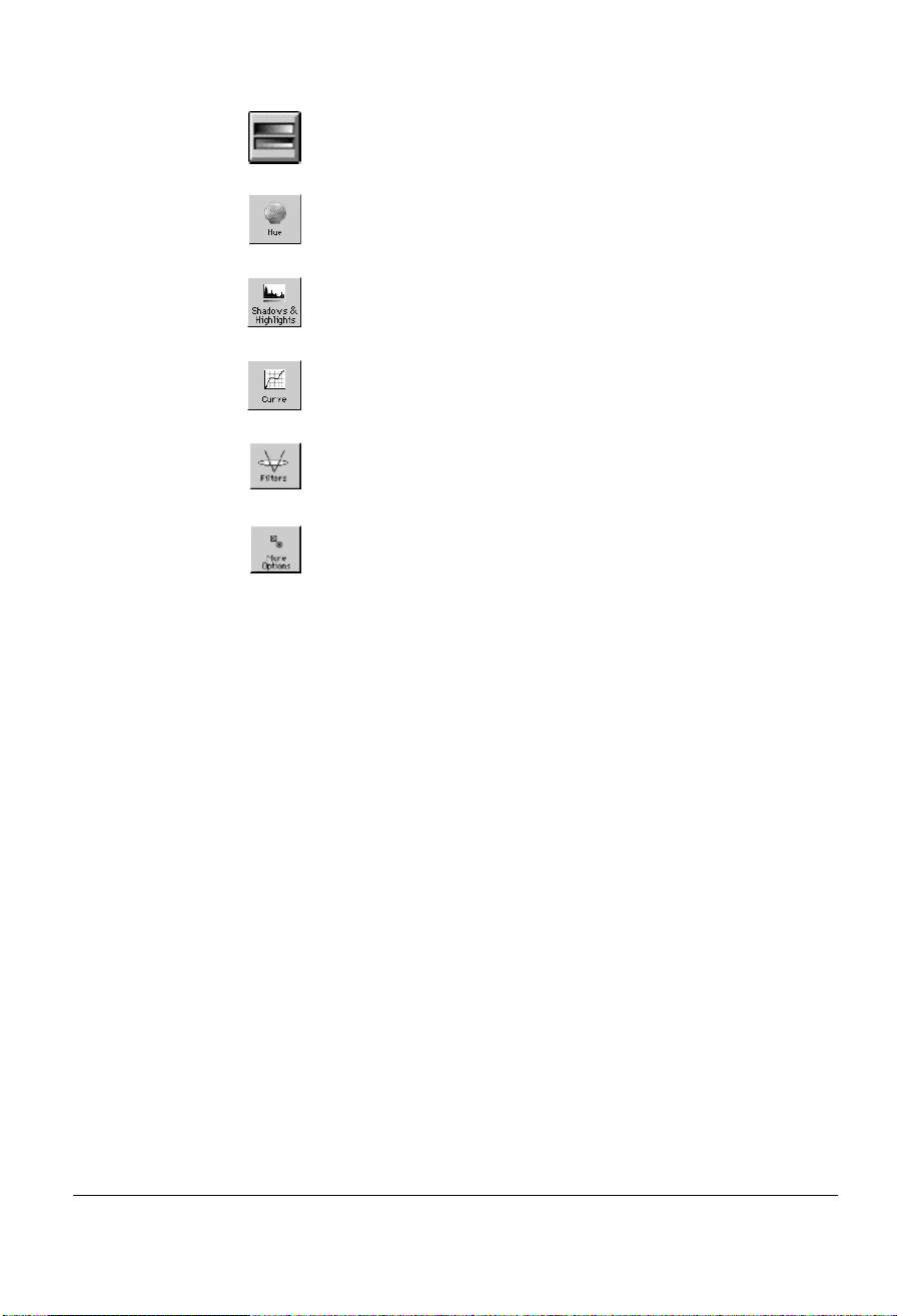
6 To adjust image quality, use the image adjustment tools in the
Settings window. These tools are (left to right) Tone; Hue;
Shadows and Highlights; Curve; Filters; and More Options.
Refer to Adjusting an image on page 3-15 for details.
7 Choose a resolution in the Settings window. A resolution that
matches the resolution of your output device produces the
best results.
Page 19

8 To scan the image, click on the Scan button in the Preview
window. The image will be scanned and delivered to your
image-editing software (e.g., Adobe Photoshop), where it can
be saved as a file.
Exiting SprintScan Macintosh
Choose Quit from the Scanner menu or press Command+Q
(the Apple command and Q keys) simultaneously.
Windows
Click on the close button on the title bar of the Preview
window.
Quick scanning 3-5
Page 20
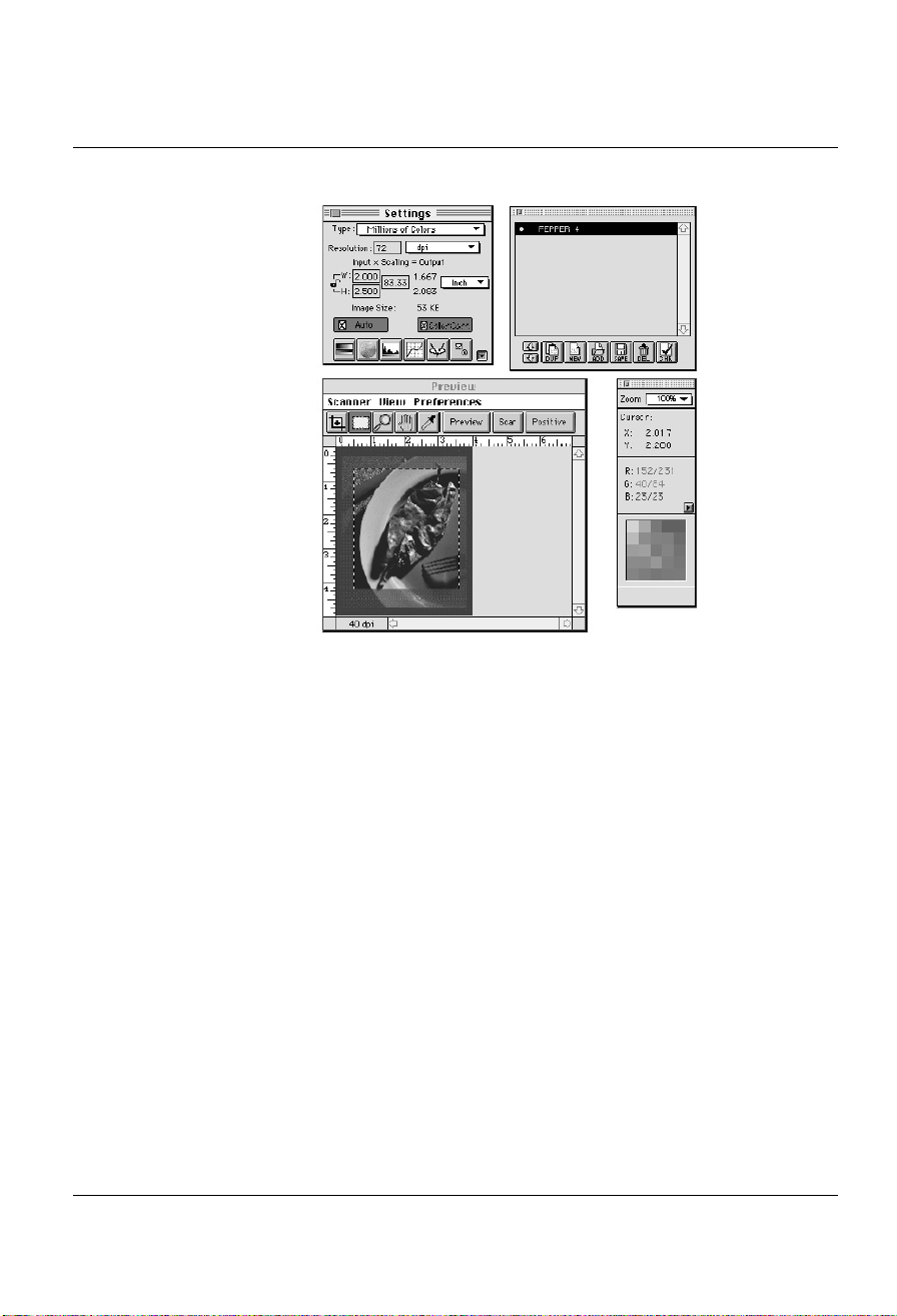
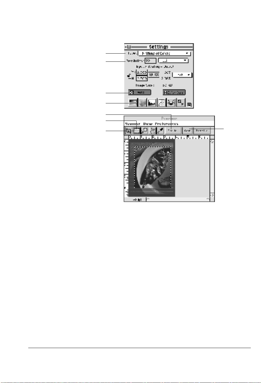
SprintScan windows and menus
ab
c
d
Windows a Settings window contains scanning parameters for
outputting the image and includes image adjustment tools.
b Scan job window provides key functions in processing sepa-
rate scans.
c Preview window has commands and tools for controlling the
scanner and provides access to the SprintScan menus from the
menu bar.
d Information window allows precise pixel-by-pixel viewing of
the input and output image information.
3-6
Page 21
f
a
b
e
c
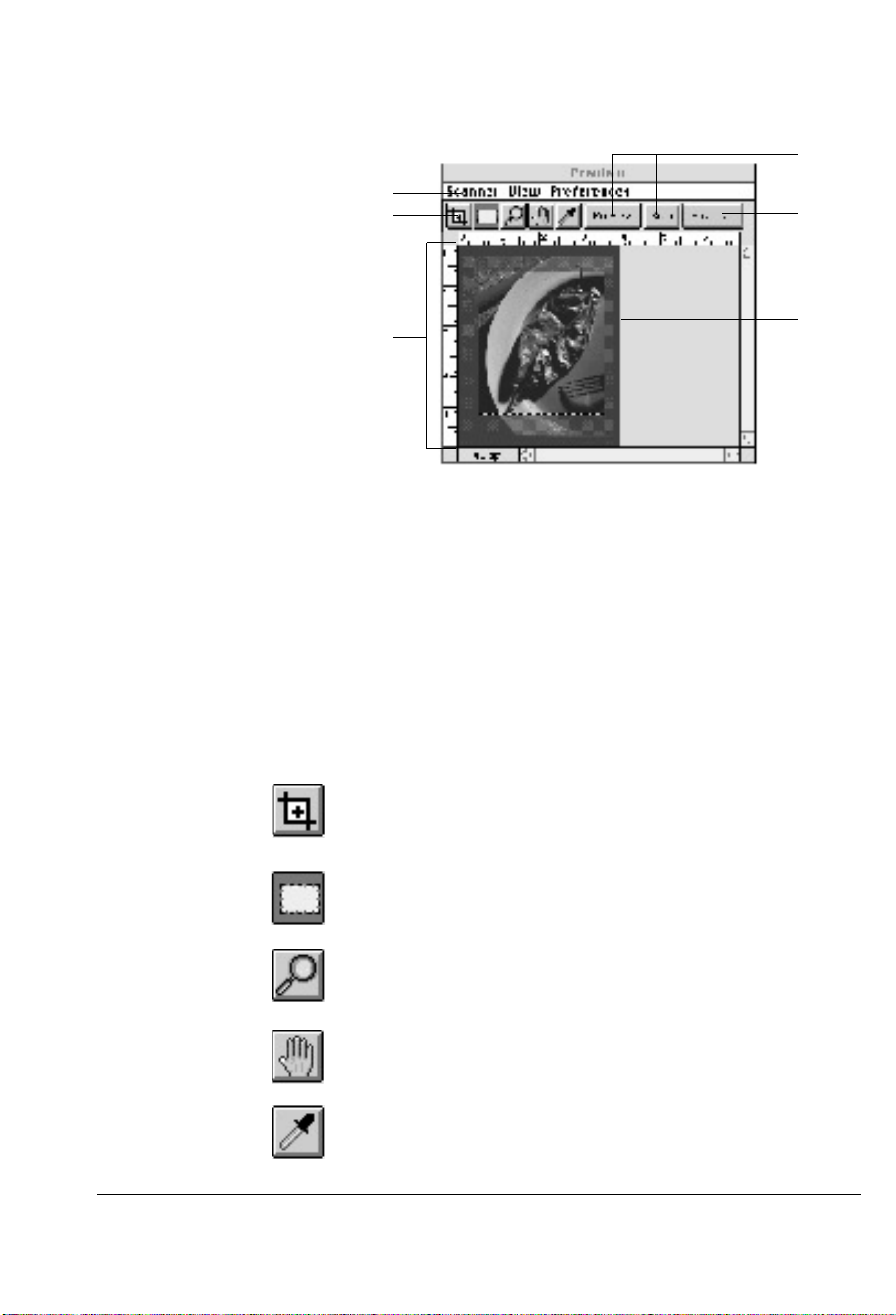
Preview window
d
The Preview window has commands and tools for controlling
the scanner, and it provides access to the SprintScan menus
from the menu bar.
a Menu Bar includes the different menus for setting up the
scanner (Scanner menu), controlling view options (View
menu), customizing the software (Preferences menu), and for
Windows, accessing on-line help (Help menu).
b Tool buttons simplify the performance of certain tasks:
Zoom Preview creates a new preview image in a higher resolution (and lets you switch between full page preview and
zoomed preview).
Scan Frame creates a scan frame or multiple scan frames in
the preview image.
Magnifying Lens zooms in or enlarges your view of the preview image.
Hand scrolls through a zoomed image and moves parts of it
into view.
Color Picker (Set Shadow and Highlight) samples color from
an area and designates new shadow or highlight points.
Quick scanning 3-7
Page 22

c Rulers are located on both sides of the window to help you
with measurement and alignment.
d Preview Area is where the preview image appears after you
click on the Preview button.
e Media Type Status button shows your scan media: positive or
negative.
Note: For Windows, the Show/Close window tool buttons
appear to the right of the Media Type Status button. These
buttons show or close the Settings, Information, and Scan Job
windows.
f Action buttons generate a specific action from the scanning
software (Preview and Scan).
3-8
Page 23
a
b
c
g
f
d
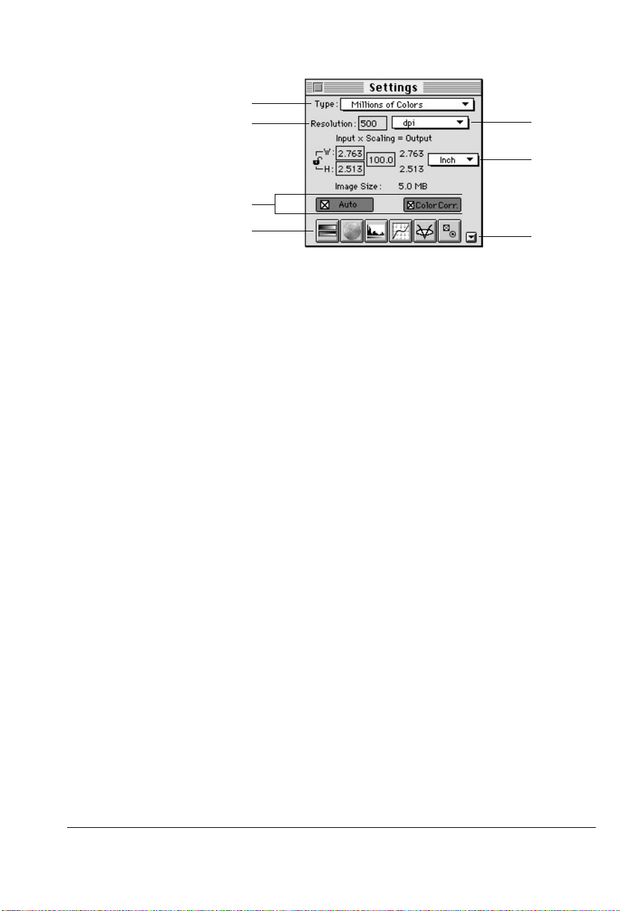
Settings window
e
The settings window contains the commands for outputting
your scanned image and includes SprintScan’s image-adjustment tools.
a Type menu lets you select the mode in which your image will
be scanned and processed.
b Resolution edit box lets you enter a resolution value in which
your image will be output (not scanned). This allows printing
with either very fine resolutions or with very high magnifications.
c Automatic adjustment controls let you automatically analyze
the image and then adjust the scanning parameters to capture
the widest density range available in the image.
• Auto optimizes contrast of the image by calculating the new
settings based on the area of the image within the scan frame,
and then applying those settings to the entire image.
• Color Correction is turned on by default for the SprintScan
35/LE to compensate for minor color shifts.
d Image adjustment tools improve image quality by enhancing
image characteristics. They allow the expert user to override
the auto controls and optimize the image for just the right
tone, color hue and sharpening. “Before and after” thumbnail
displays allow comparison of the original image and the
adjusted image.
Quick scanning 3-9
Page 24
Tone adjusts the brightness, contrast and exposure setting of
the entire image.
Hue changes the hue or saturation of an image and provides
access to negative film tables and exposure controls when
scanning negative images.
Shadows and Highlights adjusts the shadow and highlight
points of an image.
Curve adjusts the midtones, or mid-level grays, of an image.
Filters creates special effects for images.
More Options provides additional controls for adjusting your
scanner and image.
e Window Expansion button reveals the bottom half of the
Settings window, which includes shortcuts to the various
image adjustment controls.
f Image Dimension controls include parameters for specifying
input width and height, scaling, output width and height, and
unit of measure.
3-10
g Unit Selection lets you choose the unit of measurement for
resolution in either dpi (dots per inch) or lpi (lines per inch).
Page 25
a
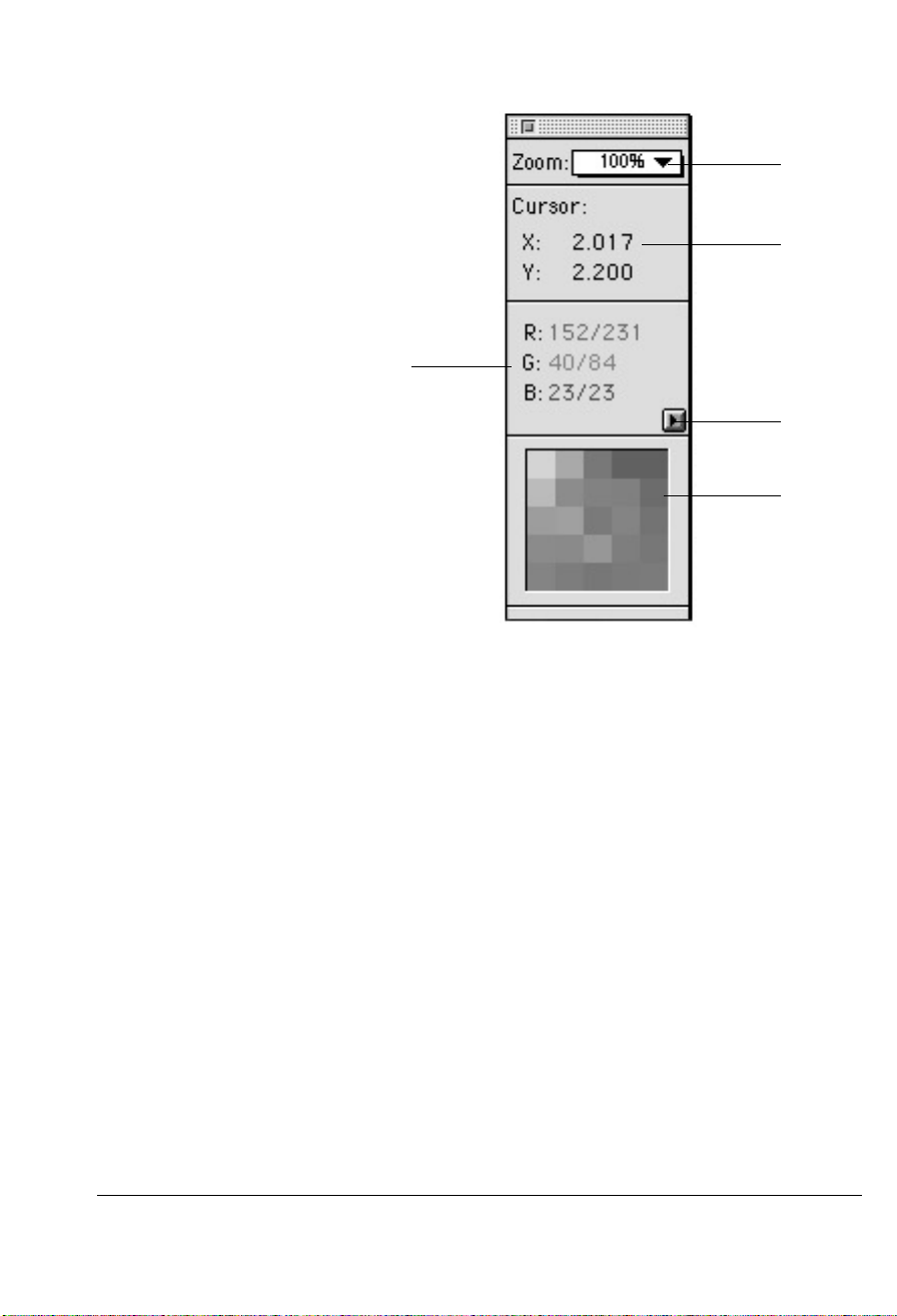
Information window
Color meter display indicates the values of the red, green
a
and blue (RGB) color channels of that image area where the
cursor is pointing. The first number is raw color data; the
second number is color data following enhancement or
modification.
e
d
c
b
b Pixel display shows the pixel and color information of the
image area where the cursor is resting.
c Sample size button lets you choose how extensively the color
information will be read, either to a single pixel or an averaged area.
d Cursor location shows where the cursor is on the coordinates
along the x (horizontal) and y (vertical) axis, based on the
unit of measurement selected for the rulers.
e Zoom Level display shows the magnification levels possible –
from 100% to a maximum of 1600% view.
Quick scanning 3-11
Page 26
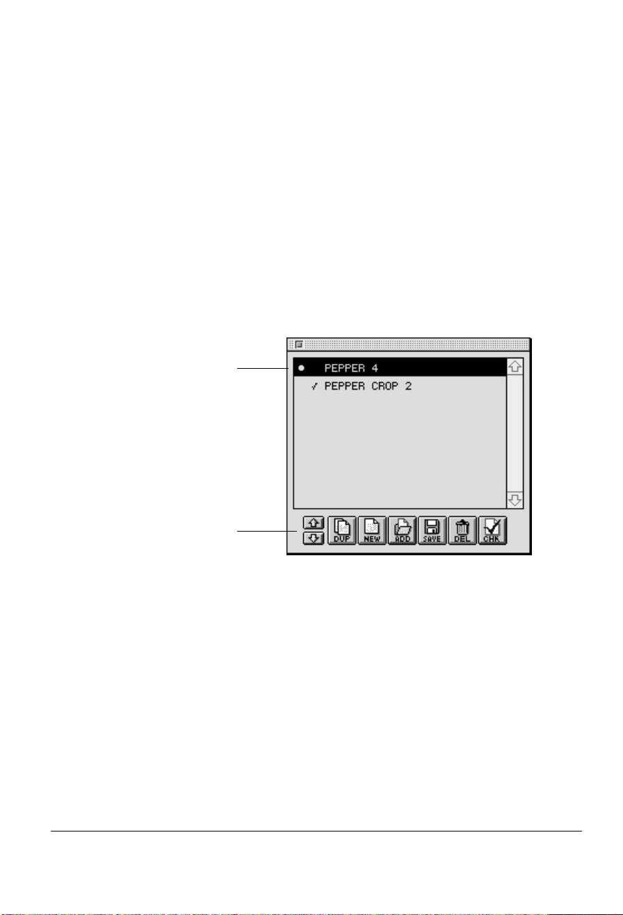
Scan Job window
The Scan Job window lets you create multiple scan jobs
(tasks) that you direct the scanner to process and scan. Each
scan job is delivered into its own file in the image-editing
application. Working with scan jobs on page 3-18 summarizes
the procedure for using this time-saving feature. You can:
• Create two or more scan jobs from a single image. The scan
jobs can be the same or different image types (e.g., color and
grayscale), and can have different brightness and contrast settings, resolution, etc.
• Create different scan jobs from multiple images. Instead of a
single image, you can have two or more images and designate
each image as a separate scan job.
a
3-12
b
a Title area shows the number of jobs that have been created.
Check marks indicate which job or jobs are to be scanned; the
highlighted title indicates the current scan job. To rename a
scan job, double-click on a scan job, type a new name, and
press OK.
b Function buttons allow you to create or manipulate the set-
tings for a scan job. Use the Up/Down position arrows to
change the order of the scan jobs.
Page 27
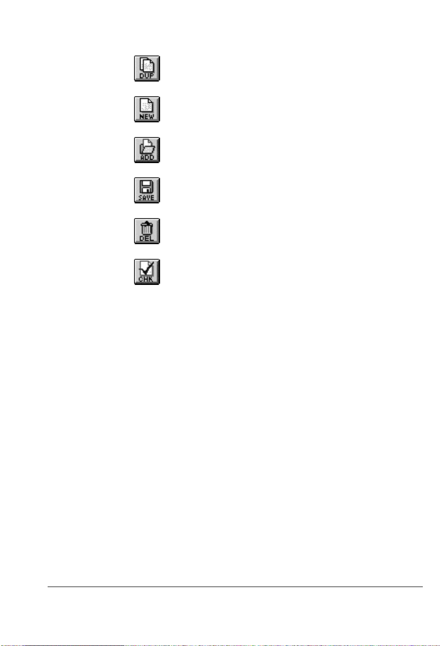
Duplicate lets you duplicate the settings of a scan job that
you can use as template for other scan jobs.
New lets you create a new scan job with the default settings.
You can create as many scan jobs as you wish and change the
settings as needed.
Add lets you add a scan job from a scan job template saved
previously.
Save lets you save the settings in a scan job to a scan job template that can be used for future scan jobs.
Delete lets you delete a scan job from the list.
Check allows you to select the scan jobs to be scanned.
Quick scanning 3-13
Page 28
a
b
c
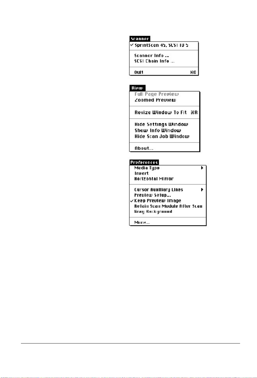
Menus a Scanner menu shows your scanner model and related infor-
mation and lets you exit from SprintScan.
3-14
b View menu provides options for controlling the way images
and windows appear in SprintScan.
c Preferences menu lets you customize the various controls and
effects that can be applied to the scan.
Page 29

Adjusting an image
To use an image adjustment tool, do one of the following:
• Click on an image adjustment tool to display the Image
Adjustment dialog box. You can apply changes there and also
switch to other tools.
Use this option for more precise control over adjustments and
to see “before” and “after” versions of the image.
• Click on the Window Expansion button to use the image
adjustment shortcut controls.
Use this option for quick results once you have become more
familiar with the tools available in the Image Adjustment
dialog box.
Quick scanning 3-15
Page 30
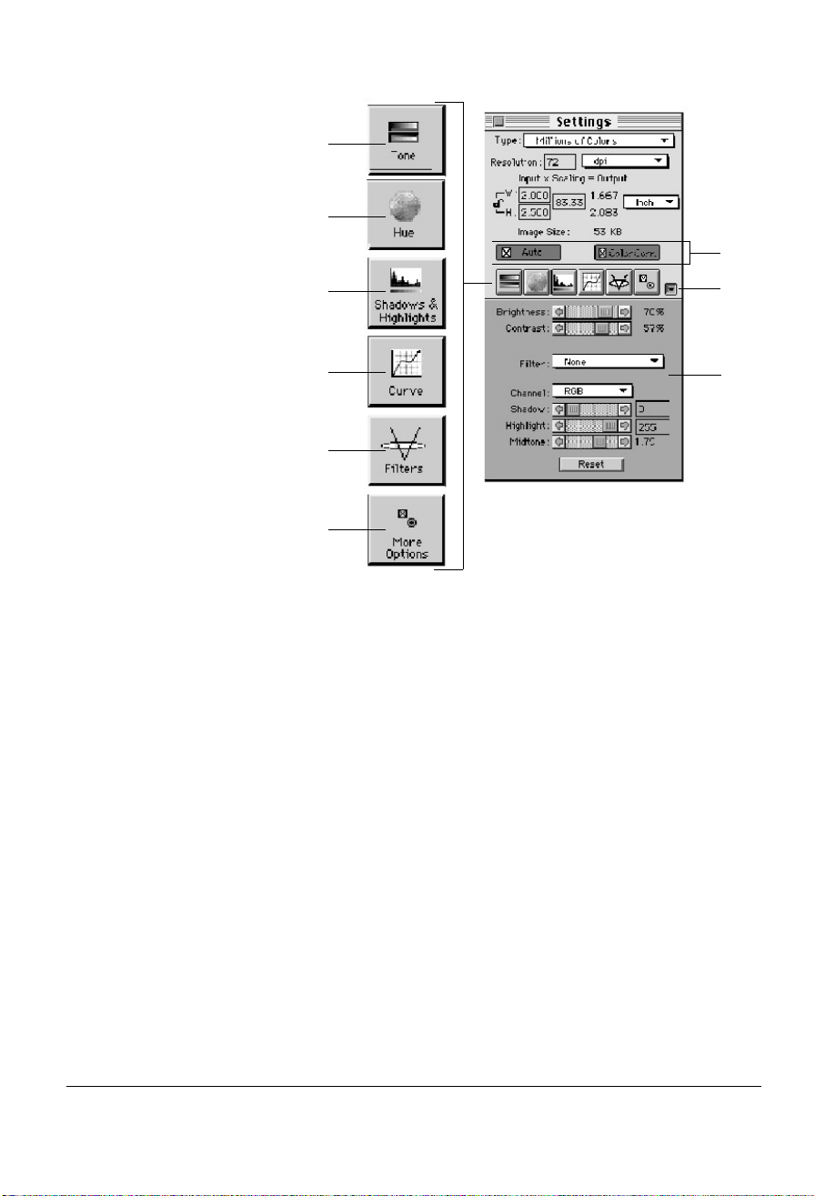
a
b
i
c
d
e
Click on any of the Image
f
a Tone adjusts the brightness, contrast and exposure setting of
Adjustment tools to display the
Image Adjustment dialog box.
h
g
the entire image.
b Hue changes the hue or saturation of an image; provides
access to negative film tables and exposure controls when
scanning negative images.
c Shadows and Highlights adjusts the shadow and highlight
points of an image.
d Curve adjusts the midtones, or mid-level grays, of an image.
3-16
e Filters creates special effects for images.
f More Options provides additional controls for adjusting your
scanner and image.
g Bottom half of the window has controls corresponding to the
image adjustment buttons.
h Click on this button to see the bottom half of the window.
i Use the Auto or Color Correction buttons to automatically
optimize image quality.
Page 31

1
4
2
Image Adjustment dialog box
3b
3a
In this box, you can do the following:
1 Select the scan job and image to which image adjustment con-
trols will be applied. (A scan job in this dialog box corresponds to the scan job in the Scan Job window). If you have
multiple scan jobs open, you can switch among these jobs and
see the image to be processed.
2 Select another image adjustment tool by clicking on any of the
buttons displayed in the vertical toolbar on the left side of the
dialog box.
3 See a thumbnail of the image captured by your scanner, and
see how the image changes when adjustments are applied to it.
The “before” and “after” images are the left and right thumbnails (3a and 3b) in the dialog box.
4 Click on an action button to achieve a particular effect.
• Click Apply to accept your changes and close the dialog box.
• Click Cancel to abandon all changes and close the dialog box.
• Click Reset to display the Reset dialog box, allowing you to
restore your default settings.
• Click Revert to cancel out the effects of the currently used tool.
If you have used three tools, for instance, Revert will preserve
the changes of the first two tools and ignore the changes made
by the third.
Quick scanning 3-17
Page 32

Working with scan jobs
The procedure in this section shows how to create different
scan jobs with the New button. While the example demonstrates how to define two scan jobs of different image types
from a single image, you can use the same principle in different applications.
Multiple scan jobs save you time because you can activate
scanning for all the checked (selected) scan jobs in a singlestep. Each job is processed in order and delivered in to its own
file in your image-editing software. For example:
• Do FPO (for position only) scans and final scans at the same
time. Assume that you need two scans with the same color
quality, but want one with low resolution for FPO and one
with high resolution for final separations. To do this, simply
set up a scan for high resolution with the color just the way
you want it, use Duplicate to create a second scan job, then
set up the second scan job with low resolution.
• Create different scan jobs from multiple images. Instead of
one image, you can begin with two or more images. You
could scan four 35mm slides and designate each image frame
as a separate scan job, make independent adjustments to each
frame, and scan them all at the same time.
3-18
Creating a new scan job
The New button lets you create a new scan job with default
settings. This feature allows you to create as many scan jobs
as you wish, with different settings as needed.
1 Click on the Preview button to see a preliminary view of the
image.
2 When the preview image appears, draw a scan frame as
shown on the upper left area of the image with the Scan
Frame tool. (If a scan frame is present, you can grab one of
the corners of the scan frame and drag towards the left).
Page 33

3 The scan job area shows the title of the current scan job
(Untitled Job). Make sure the image type selected from the
Settings window for this scan job is Millions of Colors.
Quick scanning 3-19
Page 34

4 Click on the New button in the Scan Job window. After enter-
ing a new job name, click OK.
The Scan Job window now has two titles.
At the same time, a new scan frame appears in the preview
window.
5 Draw the second scan frame around the upper right area of
the image.
6 Highlight the second scan job in the title bar in the Scan Job
window, go to the Settings window, then choose 256 Shades
of Gray in the Type box.
3-20
7 Go to the Preferences menu in the Preview window and enable
the Gray Background command.
Tip: The Gray Background command is not essential for
doing a scan job, but it helps you distinguish scan frames
more easily.
You will now see the following:
• The second scan job (the upper right area of your image) is in
grayscale.
• The first scan job (the upper left area of the image) remains in
color.
• The lower half of the image (the part not included in any scan
Page 35

frame) is hidden behind the gray background.
8 To see how the scan jobs relate to the titles in the Scan Job
window, highlight the current scan job title.
• Click on the first scan job title in the Scan Job window. The
scan job that becomes active is the upper left area of the
image (in color).
• Click on the second title, and the second scan job is activated
(upper right area of the image, in grayscale).
9 To designate the scan job to be processed and scanned, select
the scan job and click on the Check button.
The checked scan job(s) will be scanned in the order that they
appear in the Scan Job window, and they will be delivered
separately to your image-editing software.
Tip: To check or uncheck a scan job, select the scan job, then
click on the Check button.
Quick scanning 3-21
Page 36

O v e rview
4 R e f e re n c e
This chapter provides a comprehensive listing of all the
SprintScan scanning software features.
Because SprintScan provides plug-in module compliance for
Macintosh and TWAIN compliance for Windows, you can
use SprintScan to capture images placed in your scanner,
adjust those images, then place them directly into your target
application. The captured image does not have to be saved as
a separate file before being used by the application.
With its many editing tools and features, SprintScan software
can save you considerable time from having to do touch-ups
in your image-editing software.
4-1
Page 37

SprintScan software
• The Preview and Settings windows appear automatically
• The Scan Job and Information windows are accessed with the
SprintScan software consists of four major windows: Preview,
Settings, Information, and Scan Job. The reference information in this chapter is organized in four parts, and follows the
structure of the software.
whenever SprintScan is started up. The main screen also
shows any windows that were open when you last exited the
software. That is, if all four windows were open the last time
you quit SprintScan, the same four windows will appear the
next time you start it up
Preview window View menu options Show Scan Job Window
and Show Info Window.
4-2
Page 38

ab
d
c
a Settings window contains scanning parameters for outputting
the image and includes image adjustment tools.
b Scan job window provides key functions in processing sepa-
rate scans.
c Preview window has commands and tools for controlling the
scanner and provide access to the SprintScan menus from the
menu bar.
d Information window allows precise pixel-by-pixel viewing of
the input and output image information.
Reference 4-3
Page 39

Starting up SprintScan Macintosh version
Start up your image-editing software (like Adobe Photoshop).
1
2 When the application opens, choose Acquire from the File
menu.
3 Choose Polaroid SprintScan or Polaroid SprintScan PPC from
the submenu.
Windows version
Start up your image-editing software (like Adobe Photoshop).
1
2 When the application opens, choose Acquire from the File
menu.
3 Choose TWAIN_32 from the submenu.
Note: If the Scanner Control Panel does not appear, do the
following:
• Choose Acquire from the File menu and Select TWAIN_32
Source from the submenu. The Source Manager dialog box
appears so you can choose the device, or source, to be used
for image acquisition.
• Select Polaroid SprintScan and press Select.
• Choose Acquire from the File menu and TWAIN_32 from the
submenu to display the Scanner Control Panel.
4-4
Page 40

P review window
The Preview window is the most prominent of the four major
SprintScan windows. It includes the various commands and
tools for controlling the scanner.
f
a
b
e
c
a The Menu Bar includes the different menus for setting up the
d
scanner (Scanner menu), controlling view options (View
menu), customizing the software (Preferences menu), and for
Windows, accessing on-line help (Help menu).
b The Tool buttons simplify the performance of certain tasks.
The Tool buttons are (left to right):
• Zoom Preview
• Scan Frame
• Magnifying Lens
• Hand
• Color Picker
c The Rulers are located on both sides of the window to help
you with measurement and alignment.
d The Preview Area is where the preview image appears after
you click on the Preview button.
Reference 4-5
Page 41

e The Media TypeStatus button shows your scan media:
positive or negative.
Note: For Windows, the Show/Close window tool buttons
appear to the right of the Media Type Status button. These
buttons show or close the Settings, Information, and Scan Job
windows.
f The Action buttons generate a specific action from the scan-
ning software (Preview and Scan).
4-6
Page 42

a
b
c
The Menu Bar a Scanner menu shows your scanner model and related informa-
tion and lets you exit from SprintScan.
b View menu provides options for controlling the way images
and windows appear in SprintScan.
c Preferences menu lets you customize the various controls and
effects that can be applied to scan.
Reference 4-7
Page 43

Scanner menu
The Scanner menu lets you:
• Show your scanner model or select a scanner if you have mul-
tiple scanners
• Get information about your scanner
• Get information about the SCSI chain
• Exit SprintScan (Macintosh version)
Scanner model The top of the scanner menu displays the scanner model you
are using and its SCSI ID. If you have multiple scanners on
your system, all the scanners are shown with their respective
SCSI IDs, and the current scanner is indicated by a check.
Only one scanner can be accessed at a time. To switch among
various scanners, select the scanner to be used.
Scanner info The Scanner Info command provides information about the
currently selected scanner. When you choose this command, a
dialog box appears showing the scanner model, SCSI ID num-
firmware version, and driver version.
4-8
ber,
Page 44

Reference 4-9
Page 45

SCSI Chain Info The SCSI Chain Info command allows you to see the SCSI
devices on your SCSI chain and the SCSI ID number of the
devices.
By default, all SCSI ID’s are checked at startup. To allow
SprintScan to start up more quickly, select only the boxes that
match the SCSI ID of your scanner (or scanners, if you have
multiple scanners on your system). This will make SprintScan
4-10
Page 46

bypass the numbers for your other devices and focus effort on
simply detecting scanners.
To use the SCSI Chain command:
1 Choose SCSI Chain Info on the Scanner menu to display the
SCSI Chain dialog box. All the SCSI devices are shown with
their corresponding SCSI ID numbers.
2 If your scanner does not appear or if you want to update the
scanner information, click on the Probe button. Make sure
your scanner is connected and turned on.
Note: For Windows, make sure the correct interface card is
shown in the card selection box. If not, choose the correct
interface card.
3 Check the numbered box corresponding to the SCSI ID of
your scanner or scanners. Click OK to close the dialog box. If
you’re not sure about which numbers to specify, check all the
boxes.
Exiting SprintScan You can exit SprintScan at any time without scanning.
Macintosh – choose Quit from the Scanner menu or
press Command+Q (the Apple command and Q keys) simultaneously.
Windows – click on the close button on the title bar of the
Preview window.
View menu
The View menu lets you:
• Get a full page preview or zoomed-in (enlarged) view of
Reference 4-11
Page 47

an image
• Resize the preview window.
• Show or hide the Settings, Information, and Scan Job win-
dows.
• Display information on the SprintScan scanning software
(Macintosh version).
Full Page Preview The Full Page Preview command displays the image as defined
by the parameters set with the Preview Setup command (on
the Preferences menu). For instance, if your image is 4" x 5"
(the maximum size) but the dimensions in the Preview Setup
are 3" x 2", your full page preview will be 3" x 2".
You can change the size of the full page preview by setting
new dimensions with the Preview Setup command. The new
dimensions do not take effect until the next preview, which
means that you must click on the Preview button to view the
changes.
Tip: Changing the size of your full page preview may improve
performance and save memory. A smaller preview area will
occupy less memory, speed up processing, and yield a higher-
4-12
Page 48

resolution preview. This is because SprintScan takes your preview image and dynamically calculates how best to display
that image in the smaller preview area – resulting in a higherresolution view.
Full page preview is the default view. It will be dimmed if the
current view is already the full page preview. It is available for
use only if you are in zoomed preview mode.
To use the Full Page Preview command:
1 To change the size of the full page preview, click on Preview
Setup on the Preferences menu. When the Preview Setup dia-
log box appears, specify the new dimensions for the full page
preview.
2 To make the new preview dimensions take effect, do a new
preview by clicking on the Preview button. In a few moments,
the new preview area will appear.
Zoomed Preview The Zoomed Preview command displays the magnified view
that results from selecting a portion of the image with the
Zoom Preview tool and clicking inside the selected portion.
The zoomed preview displays the selected portion of the
image shown in higher resolution with more visible detail. If
you have zoomed preview enabled, the view is stored in memory, and you can easily switch between full page preview and
zoomed preview.
Reference 4-13
Page 49

Full Page preview Zoomed preview
The zoomed preview is different from the zoomed-in view
obtained with the Magnifying Lens tool, which is simply an
enlarged view, but is not in high resolution.
To use the Zoomed Preview command:
1 Choose Zoomed Preview on the View menu. This command is
available for use if the current view is full page preview, and if
a zoomed preview exits. It is disabled if the zoomed page preview is not available, or if the current view is already in
zoomed preview mode.
2 To switch to full page preview again, click on the Full Page
Preview command.
Note: For information on creating a high-resolution zoom pre-
view, refer to the section on the Zoom Preview tool button in
The Tool buttons on page 4-24.
Resize Window to Fit The Resize Window to Fit command adjusts the preview win-
dow to fit the preview area. Often, the preview window is larger than the preview area. In other instances, the preview window may exceed the preview area if you manually enlarged the
preview window (by dragging on the resize box).
To use window space more efficiently, resize the preview window by choosing Resize window to fit on the View menu.
4-14
Page 50

Tip: This command is available only if the current zoom level
is l00%, and is disabled if zoom is set to other levels. To verify the zoom level, open the Information window and look up
the zoom level.
Show/Hide commands The Show / Hide commands allow you to switch between
showing or hiding the Settings, Scan Job, and Information
windows on your screen.
To use the Show / Hide commands, do any of the following:
• Choose the correct command from the View menu for view-
ing a window. When the window appears, you can hide it by
choosing the particular Hide command for it.
P r e f e rences menu
• Click on the close button of the active window.
Tip: For Windows, do not click the close button on the title
bar of the Preview window because this will cause you to exit
SprintScan. Instead, SprintScan for Windows provides
Show/Hide tool-button counterparts in the form of three
arrowheads on the right edge of the toolbar.
1 Click on the first arrow to show or hide the Settings window.
2 Click on the second arrow to show or hide the Information
window.
3 Click on the third arrow to show or hide the Scan Job win-
dow.
Reference 4-15
Page 51

The Preferences menu lets you:
• Choose the correct media type
• Create effects like invert and mirror
• Create cursor lines to help you with alignment
• Control the size of your preview window
• Keep the preview image even after exiting SprintScan
• Keep your scan module after you finish scanning (Macintosh
version only)
• Create a gray background to help distinguish the current scan
frame from other multiple scan frames
• Set other options, such as specifying a working directory
for files
Media Type The Media Type command allows you to select the correct
media. Media can be classified into two types:
• Positives, such as slides
• Negatives, such those used to make prints
Make sure you specify the correct media type (negative or
positive) or you will get inaccurate scanning results.
4-16
Note: The Media Type function is also related to the Hue
tool, an image adjustment control that lets you adjust film
type and exposure in the Settings window.
To use the Media Type command:
Page 52

1 Choose Media Type on the Preferences menu.
2 From the pop-up menu that appears, select your media; a
check will appear next to the selected option.
Invert The Invert command creates a negative of an image. The
Invert effect is applied to the whole preview image; it cannot
be used for only a specific portion of the image.
When an image is inverted, the brightness value of each pixel
is converted to the inverse value on the 256-step color values
scale. For example, a pixel in a positive image with a value of
255 is changed to 0, and a pixel with a value of 5 is changed
to 250
To use this command, choose Invert on the Preferences menu.
A check appears next to the command when it is enabled.
Horizontal Mirror The Horizontal Mirror command allows you to flip the image
so that a mirror effect is created. The mirror effect is applied
to the whole preview image; it cannot be used for only a specific portion of the image.
To use the Horizontal Mirror command:
1 Choose Horizontal Mirror on the Preferences menu. A check
Reference 4-17
Page 53

appears next to the command when it is enabled.
2 When the mirror image appears, the scan frame will still be in
the old location. You will need to move the frame if you want
to define another area of the image.
Cursor Auxiliary Lines The Cursor Auxiliary Lines command allows you to create
horizontal and vertical grid lines with your cursor to help
4-18
define a scan frame precisely. Using the grid lines, you can
also read the measurements off your ruler more easily.
To use the Cursor Auxiliary Lines command:
1 Choose Cursor Auxiliary Lines on the Preferences menu.
From the submenu that appears, select how the cursor lines
will appear.
• On both x (horizontal) axis and y (vertical) axis
• On x axis only
• On y axis only
• None (no cursor lines)
2 Click on the Scan Frame tool.
To see how the cursor lines work, click on the top left corner
of the image as your starting point, then drag down to form a
Page 54

scan frame.
As you draw the scan frame, cursor lines will appear to help
you draw the scan frame precisely.
Release the mouse. Your scan frame will be aligned with the
cursor lines.
Preview Setup The Preview Setup command allows you to set the dimensions
of your preview area.
Note: Live Preview, Color Preview and Fast Preview are the
default settings for all Polaroid film scanners. Therefore, these
options should always be turned on in the software.
When the Preview Setup dialog box comes up, specify your
parameters.
Preview Area
The Preview Area option in the Preview Setup dialog box lets
you select the size of your preview area. Choose from the following options: maximum size or custom size.
• Maximum refers to the maximum scan area that can be sup-
ported by your particular scanner model.
• Custom will appear if you enter your own specifications in
any of the edit boxes (Width, Height).
• The Width and Height edit boxes allow you to specify the
dimensions of the preview area. Top and Left refer to the
starting points of the preview area on the x and y coordinates.
Width is the expanse of the preview area, and Height is the
depth of the preview area.
• The unit of measurement indicated on the right side of the
Top box, reflects the unit selected in the Settings window.
To set the preview area:
Reference 4-19
Page 55

1 Choose the Preview Area size. If you enter a number in any of
the edit boxes marked Width or Height, the Preview Area size
automatically changes to Custom.
2 Click OK to accept the settings; click Cancel to abandon.
3 To make the new preview dimensions take effect, do a new
preview by clicking on the Preview button. In a few moments,
the new preview area will appear.
Keep Preview Image The Keep Preview Image command allows you to retain the
last preview image you used; the preview image is kept in the
preview window after you exit SprintScan. The next time you
start up SprintScan, this last preview image is again displayed
in the preview window.
To use this command, choose Keep Preview Image on the
Preferences menu. A check appears next to the command
when it is enabled.
4-20
Page 56

Retain
Scan Module For Macintosh systems, the Retain Scan
Module after
after Scan Scan command allows you to keep the scan module (the
SprintScan plug-in) after scanning has been completed and
delivered to your image-editing software. This saves you time
because you do not need to go back to the File-Acquire
process to return to SprintScan.
b
a
To use this command, choose Retain Scan Module after Scan
on the Preferences menu. A check appears next to the command when it is enabled.
Note: This command can be used only in applications (such
as Photoshop) that allow you to retain the scan module after
the scan is completed. Some applications will not return to the
scan module even if this option is enabled.
Gray Background The Gray Background command helps you distinguish the
current scan frame from the rest of the preview area for
greater visibility of the current scan frame. It is helpful to
enable Gray Background when you are editing multiple scan
frames or applying image adjustment controls.
Reference 4-21
Page 57

With the Gray Background feature turned on, the part of the
image within the current scan frame stands out clearly to help
you work more easily.
If you have multiple scan frames, only the current scan frame
stands out, and the inactive scan frames are hidden behind the
gray background screen. The current scan frame is denoted by
the marquee (marching ants).
The Gray Background feature helps you focus on just the part
of the image to which you wish to apply controls or scan. If
you have multiple scan frames and each one has a different
setting (one in grayscale, another in color, etc.), this is also
shown clearly if Gray Background is turned on.
a Part of image not in any scan frame and thus hidden by gray
background.
b Current scan frame (with pulsing lines).
To use the Gray Background command, choose Gray
Background on the Preferences menu. A check appears next
to the command when it is enabled.
How Gray Background works with image adjustment
When the Gray Background feature is enabled, it becomes
linked with the functions of a scan frame and the way image
adjustments are applied.
4-22
If you turned on Gray Background, defined a scan frame, and
then applied image adjustments, the enhancements will
appear to be applied not only to the current scan frame but
to the rest of the material as well (even though it’s hidden
behind a gray background screen).
This, however, is only an appearance. In reality, only the
current scan frame is affected by the image adjustment, and
Page 58

the rest of the material is not changed at all.
Usage: To magnify
the view of a
preview image in
high resolution,
and to let you
switch between
full page preview
and zoomed
preview.
This becomes obvious when you have multiple scan frames in
different scan modes (for example, one scan frame is in color
mode and another in grayscale). When you click on the scan
frame with the color setting, everything seems to turn to
color. Then, when you click on the scan frame with the
grayscale setting, everything turns to gray scale.
More The More
Area to be
zoomed in with
the Zoom
Preview tool
Reference 4-23
Page 59

Usage: To create
a scan frame or
multiple scan
frames in the
preview image.
Selected image
area zoomed in
(enlarged) in
high resolution
command allows you to specify a working directory where
you can save all temporary and data files, including files for
job templates.
To use the More command:
1 Choose More on the Preferences menu to display the More
Preference dialog box.
2 Press and hold down the Working Directory box. From the
pop-up menu that appears, choose your working directory.
3 If you click on the folder icon, the Directory Browser dialog
box appears for you to choose your working directory. Click
OK to close this dialog box.
Whatever directory you specify is automatically added to the
pop-up menu (in the More Preference dialog box) for you to
choose from in the future. If the directory you specify is not
found or does not exist, a warning message appears, and the
current directory of SprintScan is used instead.
4-24
4 When you have completed your choices, click OK to close the
Page 60

More Preference dialog box.
Macintosh – for the changes to take effect, exit SprintScan
then relaunch the program.
Windows – the changes take effect immediately.
The Tool buttons
Zoom Preview tool The Zoom Preview tool creates a new, higher resolution pre-
view of the area selected with the tool. You can switch easily
between zoomed preview and full page preview.
The zoomed preview is different from the zoomed-in view,
which is obtained by using the magnifying lens tool and is not
a high-resolution view.
To use the Zoom Preview tool:
1 Click on the Zoom Preview tool.
2 Move the pointer to the preview image and draw a scan frame
around the area to be zoomed in.
Usage: To zoom
in or enlarge your
view of the preview
image.
3 Click inside the scan frame. The scanner creates a new
zoomed preview based on the selected area.
Note: To zoom in on a larger area, you may need to go to full
page preview and change the size of the scan frame.
Scan Frame tool The Scan Frame tool lets you create or modify a scan frame,
which is the active area on which controls and commands can
be applied.
The Scan Frame tool can also be used to create multiple scan
frames, but only one can be current at a time; the current scan
frame is indicated by a marquee (marching ants). The current
scan frame can be more easily distinguished if you turn on the
Gray Background command (on the Preferences menu).
To use the Scan Frame tool:
1 Click on the Scan Frame tool.
2 Move the pointer (now a crossbar) to the preview image, and
Reference 4-25
Page 61

draw a frame enclosing the area to be selected. When you
release the mouse, the scan frame will be in a marquee.
Note: To make multiple scan frames, which would add scan
jobs, hold down the Shift key, click outside any existing scan
Usage: To scroll
through an image
and move parts of
it into view.
areas in the Preview window, and drag the mouse. For more
information on scan jobs, refer to the Scan Job section on
page 4-67 of the Reference chapter.
3 To resize the scan frame, do either of the following:
• Move the cursor to any corner of the frame; the pointer will
change to a double-headed arrow. Hold down the mouse, and
drag to form a new area, then release the mouse; or
• Click on the Scan Frame tool again and restart the area selec-
tion process.
Magnifying Lens tool The Magnifying Lens tool enlarges your view of the preview
image, allowing you to set the scan frame with greater precision if you need to. Only your view of the preview image is
changed; the actual size of the image remains unaffected.
Each click of the Lens tool magnifies or reduces by a factor of
Usage: To sample
color from an area
and to designate
new shadow or
highlight points.
2 up to the maximum 1600% (see Note below).
If the portion that you want to magnify includes most of the
preview area, the lens tool will magnify the view only slightly.
To solve this, enlarge the size of the preview area (through the
Preview Setup command), or a smaller selection area.
4-26
Note: If the Information window is open, the zoom level will
be indicated. This means you can also zoom in by selecting
the appropriate zoom level in the Information window.
To use the Magnifying Lens tool:
1 Click on the Magnifying Lens tool.
2 Place the pointer – now a lens with a plus sign inside it – on
the image and click.
3 To reduce the view, hold down the Option key (Shift key for
Windows) and click again. The plus sign changes to a minus
sign.
Page 62

Hand tool The Hand tool lets you scroll through a preview image, allow-
ing you to move parts of the image into view.
The Hand tool can used for zoomed-in images (enlarged
through the Magnifying Lens tool), or images not included
completely within the frame of the preview window (for
instance, if your preview image is 6 inches wide and you
resized the width of your preview window to only 3 inches).
To use the Hand tool:
1 Click on the Hand tool.
2 Move the pointer (now a hand) to the image. Hold down the
mouse and move the hand left, right, up, or down, and see
portions of the image come into view. You can also use the
scroll bars to scroll through the image.
Color Picker tool The Color Picker tool allows you to sample color from an
area of an image and to designate a new shadow or highlight
point.
With the Color Picker tool, you can determine the color values for any pixel in an image. When you click on the Color
Picker tool and pass over a pixel, the value of that pixel will
be displayed in the Information window, based on the sample
size also selected in the Information window. Pixel value
information is useful especially when you’re making color
adjustments based on color values. (For additional details, see
the section Information Window on page 4-63.)
Shadow or highlight
To select a new shadow or highlight point:
1 Click on the Color Picker tool. Then click on the Window
Expansion button in the Settings window to see the bottom
half of the window.
2 Select a color channel in the Channel box.
3 To select a new shadow point, click on a pixel in the preview
image that will serve as the new shadow point.
Reference 4-27
Page 63

4 To select a new highlight point, hold down the Option key
(Shift key for Windows) as you click; the Color Picker tool
Unit of
measurement
box
will change and become a white-colored eyedropper.
4-28
Color information
To display color information for a pixel or an averaged area,
click on the Color Picker tool.
As you pass over a point in the image, the RGB values will be
displayed in the Color Meter Display of the Information window. These values are in turn based on the sample size selected in the Preview window. For additional details, see the section Information Window on page 4-63.
Action buttons
Page 64

The Preview button gives you a preliminary view of the image
on your scanner.
Previewing an image gives you greater flexibility, as it allows
you to apply various controls to the preview image before actually scanning it. With the preview image displayed, you can
a
b
c
g
f
d
e
apply image adjustments or crop the image before performing
the final scan.
The Scan button scans the image in your scanner and delivers it
to your image-editing software. The scanned image is based on
the specifications you have chosen in the Settings window and
on controls you may have applied to the preview image.
Rulers The rulers on both sides of the Preview window help you with
operations that need precise measurement and alignment of your
image.
You select the unit of measurement with the Image Dimension
controls, located in the Settings window.
Unit of measurement can be inch, centimeter, millimeter, point,
or pixel. The pixel option is dimmed if the selected resolution
unit is lpi.
To select the unit of measurement for the rulers:
1 Click on the unit of measurement box in the Settings window.
2 When the pop-up menu appears, select the unit of measurement.
Reference 4-29
Page 65

Preview Area The preview area is where the preview image appears.
The size of the preview can be changed through the Preview
Setup command on the Preferences menu. You can increase the
size of the preview area to see more detail in your image, or you
can reduce the preview area to save on memory.
For details on how to change the size of the preview area, refer
to the Preview Setup command on page 4-18.
Settings window
The Settings window contains the commands for outputting
your scanned image and includes the SprintScan image adjustment tools.
a The Type menu lets you select the mode in which your image
will be scanned and processed.
b The Resolution edit box lets you enter a resolution value in
which your image will be output (not scanned).
c The Automatic Adjustment controls let you adjust images
quickly with the click of a button.
• Auto optimizes contrast of the image by calculating the new
settings based on the area of the image within the scan frame,
and then applying those settings to the entire image.
4-30
• Color Correction is turned on by default for the SprintScan
35/LE to compensate for the minor color shifts that occur in all
scanning.
d The Image Adjustment tools allow you to improve image quali-
ty by enhancing image characteristics such as brightness and
contrast, shadows and highlights, and others.
e The Window Expansion button reveals the bottom half of the
Settings window, which includes the various image adjustment
controls corresponding to
d.
Page 66

f The Image Dimension controls include various parameters
for specifying input width and height, scaling, output width
and height, and unit of measure.
g The Unit Selection lets you choose the unit of measurement
for resolution in either dpi (dots per inch) or lpi (lines per
inch).
Output The output image parameters include the various controls that
Image parameters determine how your image is scanned and processed.
Type (Image Type or Scan Mode)
The Type menu determines the color information that will
result from a scan. It does not refer to the original image
mode. For instance, if you have a color image but choose 256
grayscale for the scan mode, the image is scanned and
processed as grayscale.
Because SprintScan samples color values in 12-bits per channel, it provides the capability to:
• capture very fine detail in the deepest shadow areas.
• automatically choose the best 8-bits of information per chan-
nel when set to Millions of Colors.
• output all 12-bits of information to the application when set
to Billions of Colors, allowing you to work on the entire tonal
range within applications which can work with the 12-bit
information.
Reference 4-31
Page 67

Note: To use the options Billions of Colors or 4096 Shades of
Gray, your image-editing software must provide this capabili-
ty or you will create completely distorted images. (Photoshop
2.5.1 or later provides such support; other image-editing
applications may not).
To use the Type menu, select your scan mode.
Be sure to choose the correct image type. For instance, if you
have a grayscale original, do not set image type to Millions of
Colors.
Resolution
The Resolution option in the Settings window refers to the
desired resolution for outputting the image to a device, such
as a monitor or printer. It does not refer to the resolution in
which the image is scanned. The maximum output resolution
possible is dynamically calculated by the system as determined
by the maximum scanner resolution and the scaling setting.
4-32
SprintScan allows printing with either very fine resolutions or
a
b
e
d
c
with very high magnifications. For example, scanning a
4" x 5" frame at 2000 dpi allows a 333% magnification,
enough for an 11" x 17" print at 300 linescreen halftone (or
Page 68

27" x 33" at 150 linescreen halftone). Scanning a 35mm
frame at 4000 dpi allows a 1300% magnification, enough for
an
11" x 17" full bleed at 150 linescreen halftone.
Resolution is also related to scaling, or how large or small the
image will be relative to the original. When you change the
resolution, the scaling may be affected slightly if the resolution selected has no exact equivalent in scaling.
To set your resolution:
• Enter a resolution. There is no need to press the Enter key;
typing in a value automatically inputs it into the system. If the
value you enter is too low or too high, the minimum or maximum resolution value is entered for you instead.
Note: In setting resolution, choose the setting that best
matches your output device. Remember that the higher the
resolution, the larger the resulting file will be.
Unit Selection
The unit of measurement for resolution is in dpi (dots per
inch) or lpi (lines per inch). Lpi settings are dimmed if the
ruler unit is in pixels.
To select your option:
• Choose dpi if you know precisely the resolution you need for
your image.
• Choose lpi Draft to produce resolution that is one times the
screen frequency. Draft quality may result in output images
that look a little blurred or indistinct at edges.
• Choose lpi Medium to produce resolution that is one and
one-half times the screen frequency.
• Choose lpi Final to produce resolution that is two times the
screen frequency.
Image Dimension These controls allow you to adjust the various factors that
controls affect the size of the image: the width and height of the image
selected in the scan frame (input), the scaling factor, and the
resulting dimensions of the output image.
Reference 4-33
Page 69

a This is a mathematical formula expressing the relation of the
input dimensions to scaling and how these factors affect
image dimensions when the image is scanned.
• Input width and input height refer to the dimensions of the
scan frame that you draw. For example, if the image on your
scanner is 4" x 5" and you draw a scan frame that is 3" x 4",
then your input width will show 3.000 and your input height
will show 4.000.
• Output width and output height refer to the dimensions of
the image when output to an output device (such as a monitor
or printer).
The input width, input height, output width, and output
height are affected by your scaling and whether or not the
Aspect Lock is on.
b The Aspect Lock allows you to keep the ratio of the image
width and height constant.
c The Image Size indicates how big the file will be when you
accept the dimensions shown in the edit boxes, together with
the resolution setting that you selected. Size is calculated automatically.
d The Unit of Measurement allows you to select your unit of
measure. The options include inch, centimeter (cm), millimeter (mm), point, and pixel.
4-34
e The Scaling control lets you scale the size of the input image
to the paper output size. For more details, see the Scaling section on page 4-35.
How to use the Input-Output dimensions
The Input-Output dimensions consist of four edit boxes: input
width, input height, output width, and output height. These
edit boxes are linked to the use of the Aspect Lock.
The input dimensions can be changed only when Aspect Lock
is turned off. The input boxes will be active and the output
boxes will be grayed out. The output dimensions, however,
will respond to any changes in the input boxes.
Page 70

Conversely, the output dimensions can be changed when the
Aspect Lock is on. The input boxes will be grayed out and the
input dimensions will respond to any changes in the output
boxes.
• Use the input dimensions to specify your scan frame; or if you
wish, you can simply drag on the scan frame to whatever size
you want, and the dimensions will be reflected in the input
width and height boxes.
• The output dimensions determine the width and height of
your image when output to a device such as a monitor or
printer. The output dimensions can be changed only if the
Aspect Lock is on.
The output dimensions are calculated based on scaling, output
resolution, and the scanner’s maximum scanning resolution
capability. The selected scaling and output resolution are used
to calculate the maximum possible output dimensions. If the
desired output is larger than the maximum possible output,
then the maximum output values are displayed.
How to use the Aspect Lock
The Aspect Lock preserves the ratio of the image width and
height from input to output. For instance, if your image is 2
inches wide by 4 inches high, changing it to 1 inch by 2 inches
will maintain its aspect ratio. Changing it to 1 inch by 4
inches, however, will alter its aspect ratio and distort the
image.
The Aspect Lock is a toggle. Click on it to lock or unlock.
• If the Aspect Lock is on: Changing one output edit box
(width or height) will automatically change the other dimension, as well as scaling, to preserve the aspect ratio. With
Aspect Lock on, you cannot edit the input dimensions.
Important: If you change either of the output dimensions,
you must highlight either the other output dimension or the
scaling edit box for the system to change the other output
dimension. The system will then make the calculations automatically to preserve the aspect ratio.
• If the Aspect Lock is off: Changing one input edit box (width
or height) will NOT automatically change scaling or the other
input dimension, and aspect ratio can be changed. With
Reference 4-35
Page 71

Aspect Lock off, you cannot change the output dimensions.
Important: If you change any of the input fields, press the
Enter key so that the output fields respond to the changes
(even though they remain grayed out).
Scaling Scaling is the process of creating larger or smaller images in
your scanning software so that you need not resize the images
later when they are delivered to your image-editing program.
To illustrate the use of scaling: Assume that your input dimensions are 4" x 5," and that your resolution is held constant
throughout the changes, then:
• if scaling is at 100%, output dimensions will also be
4" x 5"
• if scaling is at 50%, output dimensions will be halved to
2" x 2.5"
• if scaling is at 200%, output dimensions will be doubled to
8" x 10"
When you change resolution and specify a value that has no
exact equivalent for scaling, the scaling may be affected and
adjusts itself to the nearest allowed value. For instance, if your
resolution is 100, your scaling becomes 99 (instead of a full
100), because that is the closest scaling equivalent, given the
resolution value.
Automatic Adjustment The Automatic Adjustment controls include the Auto button
controls and the Color Correction button, located below the Image
4-36
Page 72

Dimension controls. (Color Correction is available for the
SprintScan 35/LE only.)
Both features automatically analyze the image and then adjust
the scanning parameters to capture the widest density range
available in the image. Auto and Color Correction work independently of each other and offer different advantages. Select
one function or both depending on your requirements.
Auto (Automatic Contrast Control)
The Auto button optimizes the contrast of scanned images by
making adjustments to the Shadow/Midtone/Highlight values.
Reference 4-37
Page 73

The Auto setting works by calculating the image settings of
the current scan frame and applying those settings to the
entire image.
• If you draw a scan frame around part of an image that is light
and then apply Auto, the part of the image enclosed in the
scan frame becomes darker. Auto remaps the pixels in the
entire image in relation to the scan frame and makes the entire
image darker.
4-38
Page 74

• If you draw a scan frame around part of an image that is dark
and then apply Auto, the part of the image enclosed in the scan
frame becomes lighter. Auto remaps the pixels in the entire
image in relation to the scan frame and makes the entire image
lighter.
Changing the location of the scan frame will yield different
results because a different area of the image is being analyzed.
When you use Auto, it is helpful to turn on the Gray
Background feature (in the Preferences menu in the Preview
window). This will allow you to see clearly the part of the
image within the current scan frame.
To use the Auto control:
1 Click on the Preview button to preview the image.
2 Click on the Scan Frame tool and draw a frame around the area
where Auto will be applied.
Reference 4-39
Page 75

3 Click on the Auto button in the Settings window. The option
will be checked when it is enabled.
4 If you do not like the results obtained by Auto, or if you choose
not to use it for certain images that have Auto enabled, click on
the Auto button again to deselect the feature. A message will
appear asking if you wish to reset the Shadow/
Highlight/Midtone values. Select Yes to return your image to
the original.
Color Correction
(For SprintScan 35/LE only) Color correction corrects minor
color shifts and creates an industry-standard color profile
matched to your scanner. The colors in your scanned image are
adjusted to their optimal levels.
The Color Correction button is turned on by default for the
SprintScan 35/LE, but you can turn it off by clicking on the
a
d
b
4-40
c
button again. Color Correction is dimmed in the following
instances:
• If image type in the Settings window is set to Billions of
Colors, or any grayscale setting.
Page 76

• If the media type chosen (in the Media Type command,
Preferences menu) is Negative.
Image Adjustment tools
The image-adjustment tools let you adjust the characteristics
of your image such as brightness and contrast, or shadows
and highlights, directly from SprintScan software instead of
using your image-editing software.
When you click on an image adjustment tool, the Image
Adjustment dialog box appears, with a screen corresponding
to the image adjustment tool you selected. The advantages of
using the dialog box include the following:
• View image adjustment changes in real time. The dialog box
has two thumbnails providing you with “before” and “after”
versions of an image.
• Switch among image adjustment tools without leaving the
dialog box.
• Switch among scan jobs to apply image adjustments separate-
ly.
• Reset or revert settings, providing you the flexibility to cancel
out changes or restore to default settings if needed.
Tip: It isn’t necessary to use all the image adjustment tools to
achieve a great image. For example, changing the shadows or
gamma curve may provide the results you need. Try experimenting with the tools to see which one provides optimal
results. Also, the effects of using the image adjustment tools
are cumulative – you create additional changes to the adjusted
image with each additional tool you select.
Example: If you increase brightness in an image (through
the Tone tool) and then modify the gamma curve of the
image (through the Curve tool), the curve will be based
Reference 4-41
Page 77

on the already altered brightness settings.
Using the When you click on any of the image adjustment tools in the
Image Adjustment Settings window, the Image Adjustment dialog box appears.
dialog box
This is where you select the scan job to which image adjust-
a
ment will be applied. If you have multiple scan jobs, you can
switch among the various jobs, and the thumbnails will
change accordingly to show the selected scan job.
Important: Switching to a new scan job while using the
Image Adjustment dialog box will make any changes to the
4-42
currently selected scan job permanent. This cannot be undone
even by selecting the Cancel button.
Example: Assume you have two scan jobs, Scan Job 1
and Scan Job 2. If you applied a filter (through the Filters
tool) to Scan Job 1, and then switch to Scan Job 2, the filter will be applied to Scan Job 1 even though you did not
click Apply. To undo the filter, you will need to use the
Reset button.
b To select another image adjustment tool, click on any of the
buttons displayed in the vertical toolbar on the left side of the
dialog box.
c These are the thumbnails of the image selected. The left
thumbnail is the “before” version – which shows the effects of
the last saved settings values. The right thumbnail is the
“after” version – which shows the effects of the new settings
to be added in the Image Adjustment dialog box.
Page 78

d Click on an action button to achieve a particular effect.
Action Buttons in The Action buttons in the Image Adjustment dialog box carry
the Image Adjustment out a specific action:
dialog box
Usage: To adjust
the brightness,
contrast and
exposure setting
of the entire image.
Apply button
Clicking on this button will apply whatever image adjustments you have performed on the current scan job, and close
the dialog box. Clicking Apply is not the same as switching to
another scan job (if you have multiple scan jobs). If you
switch scan jobs, the effects are applied to your current scan
job, and then the new scan job appears; you do not exit the
dialog box.
Example: If you increased brightness, changed the satu-
ration, and then clicked Apply, all the changes are
applied, and you exit the dialog box.
a
b
d
c
Cancel button
Clicking on this button will cancel out all image adjustment
changes you have made to the current scan job, and then close
the dialog box.
Example: If you applied filters, changed the curve, and
then clicked Cancel, none of the changes will take effect,
and you exit the dialog box.
Reset button
Reference 4-43
Page 79

Clicking on this button brings up the Reset dialog box, where
you can specify which settings are to be reset, then click Reset
or Cancel. If Reset is selected, the settings are restored to their
default values; if Cancel is selected, the settings remain.
Example: If you changed shadows/highlights, changed
brightness, then clicked on Reset and chose to reset
brightness, the setting of the scan job is restored to its
default; but the altered shadows and highlights remains
in effect. If you reset both shadows/ highlights and
brightness, then those values are both restored to default.
Revert button
Clicking on this button cancels out the changes you made
with the current image adjustment tool. This means that if
you used several tools (and achieved a look that is the cumulative effect of all the tools), using Revert will cancel the effect
of only the current tool and preserve the effects of the preceding tools.
Example: If you change shadows, apply filters, change
brightness, and then click Revert, the brightness changes
will be canceled out, but the altered shadows and filters
settings remain in effect.
Tone tool The Tone tool changes the brightness, contrast, and exposure
setting of the entire image.
• Brightness is the balance of light and dark shades in an image,
• Contrast is the range between the darkest and lightest shades
in the image.
4-44
Page 80

Usage: To change
the hue or
saturation of an
image.
• Exposure is similar to photographic exposure, allowing you to
increase or decrease light available to the image. The Exposure
control can allow more detail to emerge in an image, especially if it was underexposed.
The goal in using the Tone tool is to get the fullest dynamic
range possible for your image. Because the Tone tool affects
the image as a whole, you can try using the Shadows and
Highlights tool instead to get the effects you want if you find
that the Tone tool alters your image too much.
a The Brightness slider lets you change the brightness setting.
• Too much brightness can make an image look washed out.
• Very low brightness levels can make an image look very dark.
b The Contrast slider lets you change the contrast setting.
• High contrast can make an image look like a photocopy of a
picture with little or no gray shades.
• Low contrast can make an image look dull and flat.
c Exposure lets you lighten or darken the image overall. This
can be used to show more detail in an image that was over-or
a
b
d
c
underexposed.
• More exposure will provide lighter images. The higher the
exposure, the longer it takes to scan the image.
• Less exposure will produce a darker image.
Reference 4-45
Page 81

d Channel lets you select a particular color channel (red, green
or blue) for exposure adjustment.
Tone tool procedure
To change brightness or contrast, choose the Brightness or
1
Contrast control. To change values, drag on the slide bar or
click on the arrows on either side of the bar.
2 To change exposure:
• Click on the Channel box, and select the color channel to be
modified.
• Drag on the Exposure slide bar or click on the arrows on
either side of the bar.
3 Click on a button for the appropriate action.
• Click Apply to accept changes and exit the dialog box.
• Click Cancel to abandon all changes and exit the dialog box.
• Click Reset to restore settings to original default values.
• Click Revert to cancel the effect of the current image adjust-
ment tool.
Hue tool The Hue tool adjusts the hue or saturation of colors. Hue
applies only to color images and is not available for use with
grayscale or black-and-white images.
4-46
The Hue tool is useful when your image has a particular color
cast and you wish to remove the cast to make the image look
more natural.
• Hue is the aspect of color that distinguishes one color from
another (whether it is red, green, or blue). In the RGB color
model, hue can be distinguished by its position in the color
wheel.
• Saturation refers to the intensity of a color (more red in an
apple, more green in the grass). Increasing saturation can have
a dramatic effect on the colors of an image, but beware of
increasing saturation too much, as it creates artificial-looking,
overly bright colors.
Page 82

Usage: To adjust
the shadow and
highlight points of
an image.
The Hue tool is also related to the Media Type command in
the Preferences menu. For positives, the Hue tool lets you
adjust hue and saturation. For negatives, the Hue tool provides additional controls for selecting film type and adjusting
exposure.
a The Color Wheel shows you the position of colors. Blue is
across from yellow, green is across from magenta, and red is
across from cyan. By moving the pointer (a small dot in the
center of the wheel) to another place in the color wheel, the
hue of the image is altered. For instance, if you move the
pointer towards the magenta area of the wheel, the wheel will
add more magenta to the image and remove a greenish cast.
b The Saturation bar lets you change the intensity of the hues
(colors) in your image. Use Saturation selectively, because
increasing saturation will intensify all hues in the image.
c The Exposure Correction bar lets you adjust the exposure of
a negative. An overexposed image in the dialog box appears
bright (the negative looks dark), while an underexposed image
in the dialog box appears dark (the negative looks light).
• If your film is overexposed (image is too bright), drag the bar
to the left; this will make the image darker.
• If your film is underexposed (image is too dark), drag to the
bar to the right; this will make the image lighter.
Note: Film Type selection and Exposure selection are avail-
able only when media type chosen is negative.
d The Film Type Selection bar allows you to select the type of
film you used for your negative. Choosing the correct film
type is important in maintaining image quality, and you
should choose the film type that’s indicated on the packaging
that came with your film.
The Film Type Selection box provides several choices for you
to choose from. If your type of film is not in the list but simi-
Reference 4-47
Page 83

h
g
a
b
c
f
e
d
lar film types from the same company are available, you may
choose from one of them.
If your film type is not in the selection list and you cannot
find its family group, choose Generic Negative Film.
Hue tool procedure
Select the correct media type for your image in the Media
1
Type command in the Preferences menu.
2 Click on the Hue tool to display the Hue screen.
3 To change the hue of an image, move the pointer in the color
wheel to its new color position in the wheel. Click on an
action button.
4 To change the saturation of an image, drag on the saturation
bar. Dragging the slide bar to the left decreases saturation;
dragging it to the right increases saturation.
4-48
5 For negatives only:
• To choose the correct film type for your negative, click on the
Film Type Selection box and make your selection. If your film
type is not in the list, select Generic Film Type.
• To correct the exposure of a film, use the Exposure
Correction bar. To correct overexposure and make the film
darker, drag the triangle to the left. To correct underexposure
and make the film lighter, drag the triangle to the right.
6 Click on an action button.
• Click Apply to accept changes and exit the dialog box.
Page 84

• Click Cancel to abandon all changes and exit the Image
Adjustment dialog box.
• Click Reset to restore settings to original default values.
• Click Revert to cancel the effect of the current image adjust-
ment tool.
Shadow and The Shadows and Highlights tool lets you select the darkest
Highlights tool point (shadow) and the lightest point (highlight) of an image.
By using this tool, you can manipulate shades so that the
Shadow point becomes the new darkest value and the Highlight
point becomes the new lightest value. Shades that are darker
than the shadow then become black, and shades lighter than the
highlight become white. For example, if you set the highlight
point to 200, all points in the image with a value greater than
200 will be mapped to a value of 255, since 255 represents the
“whitest” white.
The Shadows and Highlights tool can be used for both
grayscale and color images. If you have a limited range of grays
between your lightest and darkest point, using shadows and
highlights will have the effect of extending the range of grays
and make more detail in the image visible.
a The Histogram is a graphic representation of how all the pixels
in an image are distributed across brightness and darkness levels. The darkest pixels are at the left; the lightest pixels are at
the right.
• A histogram skewed heavily to the left indicates that the image
has many more dark pixels than light.
• Conversely, a histogram skewed heavily to the right will indi-
cate a light image as it has more light pixels than dark.
• The height of the histogram indicates the number of pixels at
Reference 4-49
Page 85

that point in the histogram .
b The Triangles (indicators) below the histogram adjust the
Shadow, Midtone, and Highlight settings.
• The black (left) triangle controls the shadows. Moving this
triangle to the right will emphasize shadows and create a
darker image.
• The gray (middle) triangle controls the midtones and indicates
how the brightness and darkness pixels are divided. Moving it
to a value less than 1.0 (left) will have the effect of darkening
the image. Moving it to a value greater than 1.0 (right) will
have the effect of lightening the image.
• The white (right) triangle controls the highlights. Moving this
triangle to the left will emphasize highlights and create a
lighter image.
Note: The gray and white triangles will change in color if a
color channel (not RGB) is selected in the Channel box.
c The Histogram bar shows the distribution of shades from
dark to light (left to right). The distribution of shades changes
as you move any of the triangles.
d The Output edit boxes show the 0 to 255 pixel range to
where the Input levels are mapped. For example, if you modified input values to 30 and 255 and then change output values
to 0 to 250, the input values of 30 to 255 will be “stretched”
to fit the output range of 0 to 250. This means you have a
total of 250 shades (250-0=250).
4-50
• Unless you have very specific effects in mind, it is better to
leave this feature alone, so that everything is always mapped
to 255 shades (255-0). You can experiment with this feature
to
see what it does, however, and how it interacts with the input
levels.
e The Input edit boxes show how pixels are distributed over the
0 to 255 pixel scale.
• The input values are related to the position of the indicators
along the histogram. For example, if you move the left triangle in from 0 to 30, the input range becomes 30 to 255, and
Page 86

pixels in the range of 0 to 30 are then set to 0. In a process
called mapping, the new range (30 to 255) is stretched back to
become 0 to 255. The image then becomes darker, since all
pixels from 0 to 30 are now mapped to black (whereas 0 to
30 before had subtle gradations from black that lightened
gradually).
• The same principle applies when you move in the right trian-
gle, and the highlights in the image become more pronounced.
• Moving in any of the triangles above the input boxes will
change the values in the boxes. You can observe how the values in the boxes are affected by moving the triangles, or you
can enter values into the boxes directly. In both cases, the histogram will change accordingly.
f The Input/Count/Percent figures provide information about
the histogram. The figures will appear only when the cursor is
inside the histogram or if a triangle is being moved.
• Input value indicates the color value of the data displayed in
the histogram.
• Count value indicates the number of pixels at the Input value.
If Input value is 2 and Count value is 1300, then there are
1300 pixels in the image at the input value of 2.
• Percent value is the percentage of all pixels in the image
where color value is less than or equal to the input value. If
Percent is 15% and Input value is 2, it means that 15% of all
pixels in the image have a value of 2 or less.
g The Channel button lets you control the Shadow and
Highlight settings for a particular color channel (red, green or
blue) or for the RGB channel (red, green, and blue simultaneously) .
h The Original/Enhanced box lets you choose which histogram
to see: the original, before the image was modified; or
enhanced, after the image had been modified (with shadows
and highlights or any other tool).
Shadow and Highlights tool procedure
Choose the channel in which the histogram will be modified.
1
Reference 4-51
Page 87

• Select RGB to modify the histogram in the red, green, and
blue color channels simultaneously.
• Select color channels individually (red, green, blue) to modify
the histogram in that particular channel.
• For grayscale scanners, only the gray channel is available.
2 Move the black, gray, and white triangles to change shadows,
Usage: To adjust
the midtones or
mid-level grays, of
an image.
4-52
midtones, and highlights, respectively. The values in the input
edit boxes will change accordingly.
• To make the image darker, move the black triangle to
the right.
• To make the image lighter, move the white triangle to
the left.
• To change the midtones, move the gray triangle. If the mid-
Page 88

b
c
a
d
e
tone value is less than 1, the image becomes darker. If the midtone value is greater than 1, the image becomes lighter.
3 Click on the Display box to view histograms of the original
image and the resulting (Enhanced) image.
• Select Original to see the histogram before changes were made
Reference 4-53
Page 89

to the image.
• Select Enhanced to see the histogram after changes were made
to the image.
4 Click on an action button.
• Click Apply to accept changes and exit the dialog box.
• Click Cancel to abandon all changes and exit the dialog box.
• Click Reset to restore settings to original default values.
• Click Revert to cancel the effect of the current image adjust-
ment tool.
How to read and correct a histogram
A histogram shows how the brightness and darkness levels are
distributed in an image. The darkest pixels are at the left, and
the lightest pixels are at the right.
An image with good contrast will have a histogram with vertical lines spread across the scale from left to right. Here, the
histogram is heavily skewed to the left (where the darkest pixels are) indicating a dark image.
To change the histogram, and thus the image, use the three triangles below the histogram.
4-54
The pixels displayed in the original histogram are mostly on
the left (where the black triangle is) indicating a dark image.
The range of spread is also broad and flat, with almost no pixels for the midtones and highlights where the gray and white
triangles are.
In the corrected image, the triangles have been moved to new
locations. The net effect is to narrow the distribution range of
the pixels and lighten the image.
Generally, the best thing to do is to move the black and white
triangles to the start and end of the curve, and move the gray
Page 90

triangle to somewhere in between.
For example, if your graph starts at about value 20 and ends at
240, move the black triangle to 20 and the white triangle to
240. Then move the gray triangle to somewhere in the middle
between the black and white triangle for good overall balance.
Curve tool The Curve tool lets you control the intensity affecting the mid-
level grays (midtones) of an image. Adjusting the tone curve
lets you change the values of the middle range of gray tones
without dramatically altering the shadows and highlights.
In many ways, the Curve tool gives you the most control for
adjusting an image’s values, but novice users may need some
time to master the tool fully.
a The Curve is a graphic representation of the tone curve, show-
ing scanner input from dark on the left to light on the right.
b The Method sets the kind of curve you wish to have. Select
from Curve, Line or Gamma.
c The Channel allows you to choose the color or gray channel in
which the gamma will be affected.
d Input/Output/Zoom:
• Input shows the input value of wherever the cursor is pointing
on the horizontal axis of the curve.
• Output shows the output value of wherever the cursor is
pointing on the vertical axis of the curve.
• Zoom indicates the magnification level of the curve box. At
100% zoom, the curve is seen in its entirety. Using the
Magnifying Lens tool (discussed below) to magnify the curve
will zoom in or enlarge your view of the curve, resulting in a
higher zoom percentage (for example, 200%).
e The Curve tools let you modify the curve. The tools are (left to
right) the pointer, magnifying lens, and hand.
Using the Curve tools
The Curve tools allow you to modify the curve in the Curve
screen. The tools are the Pointer, Magnifying Lens, and Hand.
Use the Pointer tool to define points in the curve that will be
modified. When you click on any point in the curve, a control
point appears to mark your position. To remove a control
Reference 4-55
Page 91

point, drag it off the graph.
Use the Magnifying Lens tool to zoom in on a particular point
in the curve. Once the area is zoomed in, you can then use the
pointer tool to define new points for more precision. This is
particularly useful for working with 12-bit images, as more
detail can be seen in such images. The zoom level can be seen in
the Zoom indicator (item
d above). To zoom out, hold down
the Option key (Shift key for Windows) and click on the mouse
simultaneously.
Use the Hand tool to scroll through the curve if the curve has
been zoomed in. The Hand tool can be used only if the curve
has been zoomed in with the Magnifying Lens tool. Otherwise,
the Hand tool will be dimmed.
4-56
Curve tool procedure
Choose the channel in which the curve will be modified.
1
Page 92

Usage: To create
special effects for
images.
• Select RGB to modify gamma in the red, green and blue color
channels of the image simultaneously.
• Select color channels individually (red, green, blue) to modify
the tone curve in that particular color channel, if desired.
• For grayscale scanners, only the gray channel is available.
2 Choose the Method in which the curve will be modified; select
from Line, Curve, or Gamma.
There is no difference in the method you select, and the choic-
es are provided to give you more flexibility in adjusting the
curve.
3 Choose a curve tool; select from Pointer, Magnifying Lens, or
Hand.
4 Click on the curve to define the points where the curve will be
modified. You can then either raise or lower the curve at that
point and see changes to the image accordingly.
5 Click on an action button.
• Click Apply to accept changes and exit the dialog box.
• Click Cancel to abandon all changes and exit the dialog box.
• Click Reset to restore settings to original default values.
• Click Revert to cancel the effect of the current image adjust-
ment tool.
6 To save a curve, click on the Save button. A dialog box will
appear.
• Save the curve in either SprintScan or Photoshop format. The
SprintScan format allows you to have as many as 64 control
points in the curve for more precision; Photoshop allows a
maximum of 19.
• Choose the Channel. Select All if your channel (in #1) is RGB;
select Current if you selected one of the three color channels
(red, green or blue).
Reference 4-57
Page 93

To use a previously saved gamma curve for another image,
click on the Load button, then specify the curve to be loaded.
Photoshop-saved curves can also be loaded.
4
1
How to read the curve
Original curve Modified curve
3
2
The curve shows the relationship of the brightness changes
across the middle pixels between the resulting image and the
original.
When you open the Curves dialog box, the line on the graph
is diagonal because the Input and Output values are the same.
4-58
Page 94

The x axis of the graph represents the original brightness values of the pixels, from 0 to 255; the y axis represents the new
brightness values. Clicking on the diagonal line then plots a
point that can be adjusted.
When the curve is moved up or down, the relationship
between input value and output value changes accordingly.
Original image Modified image
• In areas where the curve is moved down, pixels in that por-
tion of the image are darkened.
• In areas where the curve is moved up, pixels in that portion of
the image are lightened.
Contrast in an image can be seen by the angle of the line. The
steeper the slope, the higher the contrast. The closer the line is
to horizontal, the lower the contrast.
Filters tool The Filters tool lets you apply or create special effects to your
images. This tool is disabled when your image type is set to
Billions of Colors, or 4096 Shades of Gray (grayscale).
The filters include:
• Blur
• Blur More
• Sharpen
• Sharpen More
• Unsharp Mask
Blur Filters
The Blur filters eliminate noise in the parts of the image where
significant color transitions occur. The Blur filters decrease
the contrast between adjacent pixels, making the image
appear hazy and out of focus.
Reference 4-59
Page 95

Usage: For
additional controls
in adjusting your
scanner and image.
• Blur smoothes out the transitions by lightening pixels next to
the hard edges of defined lines and shaded areas.
• Blur More produces an effect three or four times stronger
than Blur.
Sharpen Filters
The Sharpen filters do the opposite of the Blur filters and
increase the contrast of adjacent pixels, making images appear
sharper and more focused.
Both Sharpen and Sharpen More filters improve clarity. The
Sharpen More filter has a stronger sharpening effect than the
Sharpen filter.
Filters tool procedure
1
Click on the Filters tool in the Settings window. When the
Image Adjustment dialog box appears, click on the Filter box.
2 To preview filters and see their effects immediately, click on
the Simulate on Preview box.
3 Select the filter to be used from the pop-up window:
Note: The image you obtain in the preview when you use the
Filters tool may differ from the way the image will appear
when you scan it in. This depends on your resolution, and the
higher the setting, the less obvious certain filters (like Blur)
will have.
4-60
4 Click on an action button.
• Click Apply to accept changes and exit the dialog box.
• Click Cancel to abandon all changes and exit the dialog box.
• Click Reset to restore settings to original default values.
• Click Revert to cancel the effect of the current image-adjust-
ment tool.
Unsharp Masking
The Unsharp Masking filter adjusts the contrast of edge detail
Page 96

and creates the illusion of more image sharpness. This filter
can be useful for refocusing an image that has become blurry
from interpolation or scanning.
To use Unsharp Masking:
1 Choose Unsharp Masking from the Filters menu. The Unsharp
Reference 4-61
Page 97

Mask dialog box appears.
2 Enter a value in the Amount box to specify the percentage of
Click here
to expand
the filter’s effect. The higher the percentage, the stronger the
effect of the filter.
3 Enter the Radius value in pixels. The radius determines the
depth of pixels that will be affected at the edge.
4-62
• With a high value, more of the pixels surrounding the edge
pixels are sharpened.
• With a low value, only the edges are sharpened.
4 Enter a value in the Threshold box.
This option allows you to specify a tolerance range to prevent
overall sharpening that might generate noise or cause other
Page 98

unexpected results.
The Threshold defines the required range of contrast between
adjacent pixels before sharpening is applied to an edge. A
lower value produces a more pronounced effect.
More Options tool The More Options tool provides you with additional scanner
and image controls. These controls include:
• Scan Quality
• Gray Scan CCD Filter
a
b
c
e
d
• Use Linear Gamma Curve
Scan Quality
This option allows you to select the quality of your scans.
• Choose Draft if you’re outputting images as drafts. This
option speeds up the scanning process, but the image may be a
little coarse (compared to the Final option).
• Choose Medium if you wish to have a scanned image of better
quality. This option is slower than Draft.
Reference 4-63
Page 99

• Choose Final if you wish to have a scanned image of the best
quality. This option, however, is the slowest.
Gray Scan CCD Filter
This option allows you to select a particular color channel
when scanning grayscale images and is useful for obtaining certain effects.
When scanning grayscale images, one of the color channels of
the CCD can be used for scanning; this could be the red, green,
or blue color channel. For some scanner hardware types, this
setting may default to gray.
Use Linear Gamma Curve
This option allows the scanning software to read only raw
image data, so that no color adjustment (not even the generic
color correction profile) is applied to your image when it is
scanned.
This control is helpful for professional graphic designers who
wish to create very specific effects and are thoroughly familiar
with the scanning process. If you are not familiar with this feature, leave this option turned off.
More Options tool procedure
1
Click on the More Options tool in the Settings window.
2 When the More Options screen appears, select the particular
control to be modified and its option, then click Apply (OK for
Windows).
Window Expansion button The Window Expansion button lets you expand the Settings
window to its full size, with the bottom half of the window
revealing shortcuts to the image-adjustment controls.
When the bottom half of the Settings window is open, you can
use the image-adjustment functions directly by dragging on the
slide bars for each control. This is like clicking on an imageadjustment tool, which takes you to the Image Adjustment dialog box where you can change the controls.
4-64
Page 100

I n f o rmation window
a The Zoom Level Display shows the magnification levels possi-
Using the slide bars to adjust images may be faster, but using
the image-adjustment tools gives you greater control over
adjusting images and shows you “before-and-after” images in
the dialog box.
To close the bottom half of the window, click on the Window
Expansion button again.
The Information window provides information on the cursor
and the preview image. It also allows you to change zoom levels directly, in much the same way as using the Magnifying
Lens tool in the Preview window.
The Information window is a “floating window” and does not
appear when you start up the scanning software unless you last
exited the scanning software with the window open. To display the information window, click on the Show Info window
command in the View menu (in the Preview window).
ble – from 100% to a maximum 1600% view.
b The Cursor Locator shows where the cursor is on the coordi-
nates along the x (horizontal) and y (vertical) axis, based on
the unit of measurement selected for the rulers.
c The Color Meter Display indicates the values of the red, green,
and blue (RGB) color channels of that part of the image to
where the cursor is pointing. The numbers represent the values
in the 0-to-255 pixel range.
d The Pixel Display shows the pixel and color information of
the image area where the cursor is resting.
Reference 4-65
 Loading...