

Page 1
User Guide
SP 350
Page 2

1. Introduction..................................................................................
2. Unpacking....................................................................................
3. System Diagrams........................................................................
4. Connecting Up.............................................................................
5. Loading Film................................................................................
6. Lighting Techniques.....................................................................
7. Printer Settings............................................................................
8. Capturing The Customers Image................................................
9. Printing The Captured Image......................................................
10. Improving The Focus Setting......................................................
11. Approximate Depth Of Field.......................................................
12. Display Screen Adjustment.........................................................
13. Colour Adjustment......................................................................
14. Film.............................................................................................
15. Troubleshooting...........................................................................
16. Specifications..............................................................................
17. EMC Statement (Europe)..........................................................
18. SP350 Warranty / Ser vice..........................................................
3
3
4
6
8
10
12
14
14
16
16
17
17
23
26
27
27
28
CCoonntteennttss
page 2 of 28
Page 3
The Studio Polaroid 350 is a video based imaging system which allows
you to quickly and easily take instant photographs to meet a variety of
photo-identification needs. This guide describes all the features of the
Polaroid SP350. It takes you from unpac king the bo xes to setting up the
system through any trouble-shooting problems you may have. All
bracketed numbers refer to the diagrams of the camera and printer
shown in section 3.
System will arrive in two boxes as follows
a. Printer, film holder,
power supply, mains
cable and Polaroid
film.
b. Camera, strobe,
batteries, camera
cable, user guides,
calibration overlay,
grey card and colour
adjuster.
Carefully unpack the
contents of both
boxes.
11.. IInnttrroodduuccttiioonn
22.. UUnnppaacckkiinngg
page 3 of 28
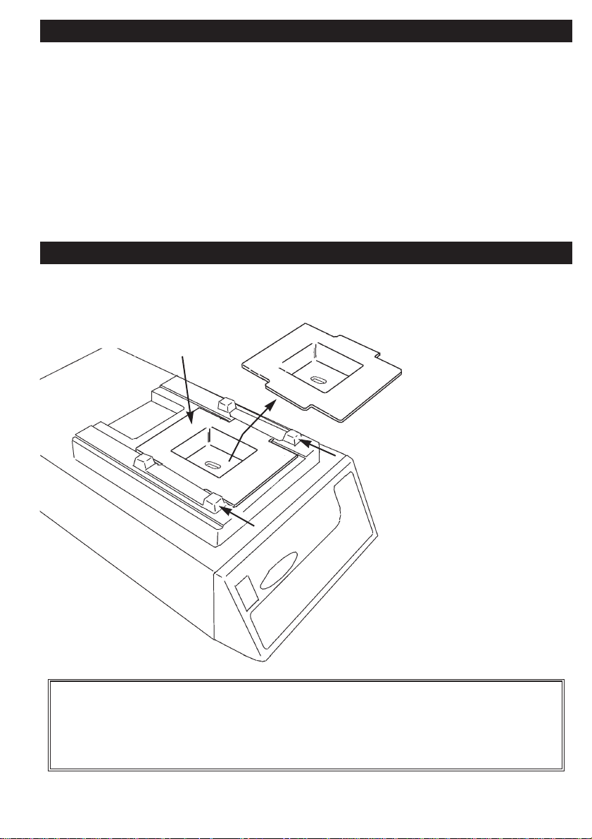
travel bracket
Important: Remove the travel bracket from the printer as shown
above by unscrewing the locking scre w and washer. After removing,
replace the screw and washer. Keep the travel bracket in a safe
place for future shipping of the printer.
Page 4
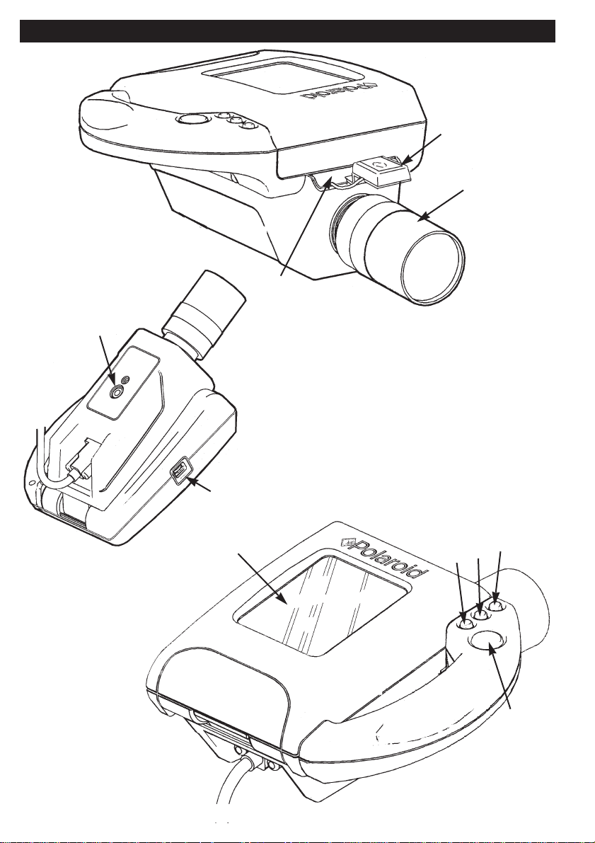
1. Preview screen
2. Hot shoe
3. CS mount access cover
4. Lens
5. Live / freeze button
6. Print format button
7. Print button
8. Film button
9. Tripod mount point
10. Brightness dial
2
4
3
9
10
1
8
7
6
5
page 4 of 28
33.. SSyysstteemm DDiiaaggrraammss
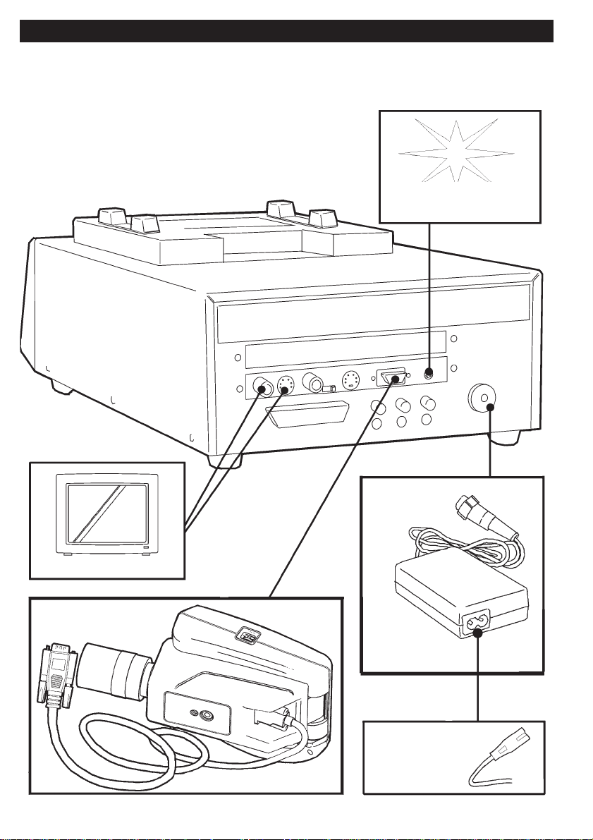
Page 5
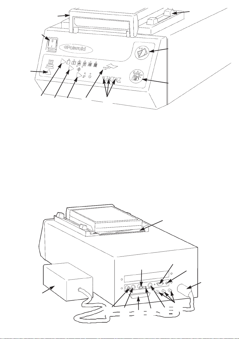
11. Power switch
12. Film holder
13. Locking mechanism
14. PC switch
15. Print format switch
16. Film switch
17. Lighting switch
18. Pull tab / out of film indicators
19. Film peel time indicators
20. Live / freeze switch
21. Print switch
22. Dark slide
23. Power supply
24. Video out (CVBS)
25. S-Video out (Y/C)
26. PC parallel connector
27. Video in (CVBS)
28. Video /S- Video input switch
29. S-Video in (Y/C)
30. Colour compensation controls
31. Power inlet
32. Strobe X-sync connector
33. SP camera connector
12
13
14
15
16 17
18
19
20
21
22
23
24
25
26
27
28
29
30
32
33
31
11
page 5 of 28
Page 6
page 6 of 28
Use the diagram below to connect up the SP 350 system
optional external
strobe
power supply
mains power
SP302 camera
optional monitor
44.. CCoonnnneeccttiinngg UUpp
Page 7
page 7 of 28
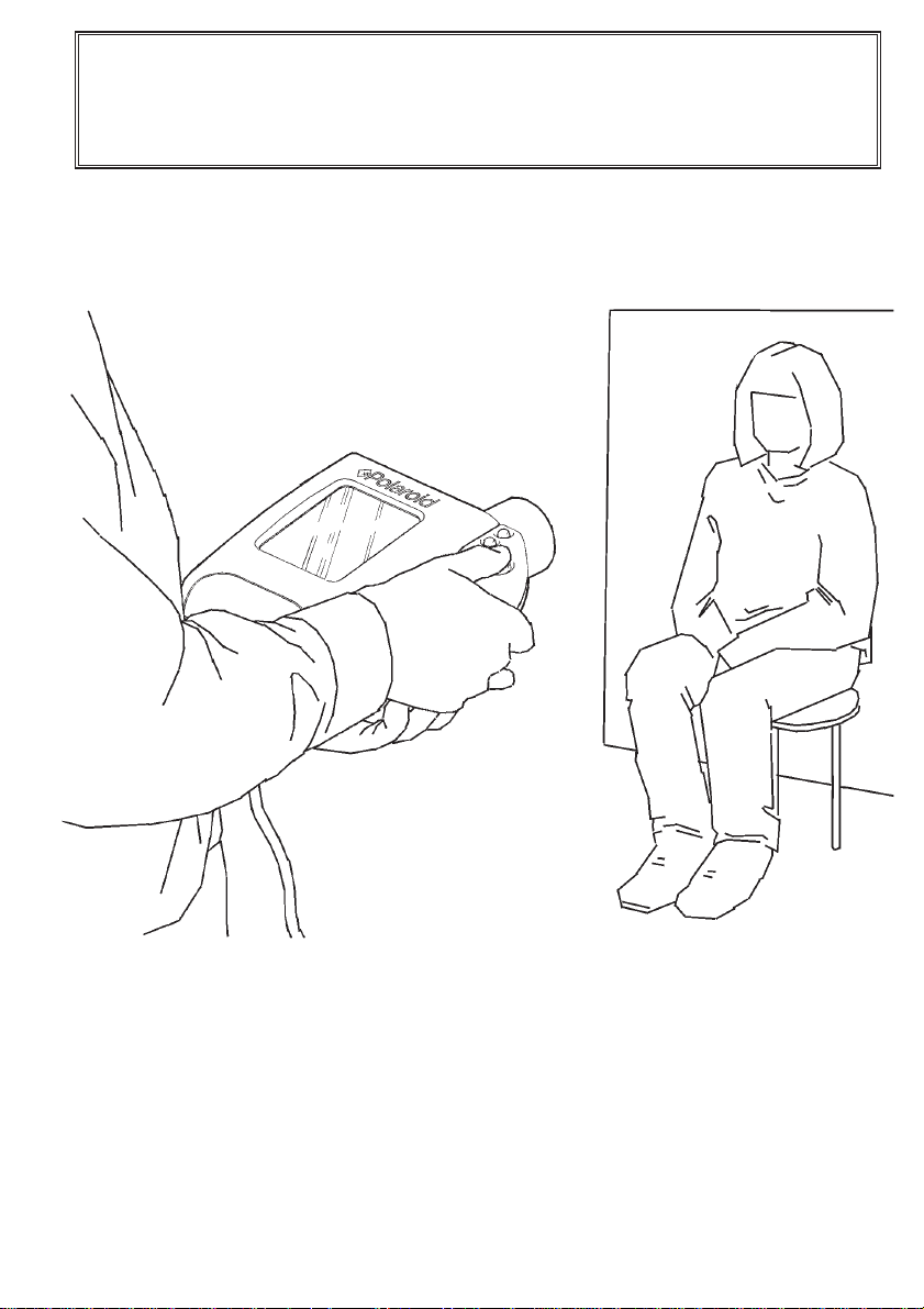
The camera can either be tripod mounted or hand held, as shown
below. Sit the pr inter on a nearby work surface.
Power up the system by switching the power switch (11) on the front
panel of the printer.
Important: Switching on the printer with the travel bracket in place
may damage the printing mechanism. Ensure the travel bracket has
been removed from the printer as described on page 3 before
powering up the system
Page 8
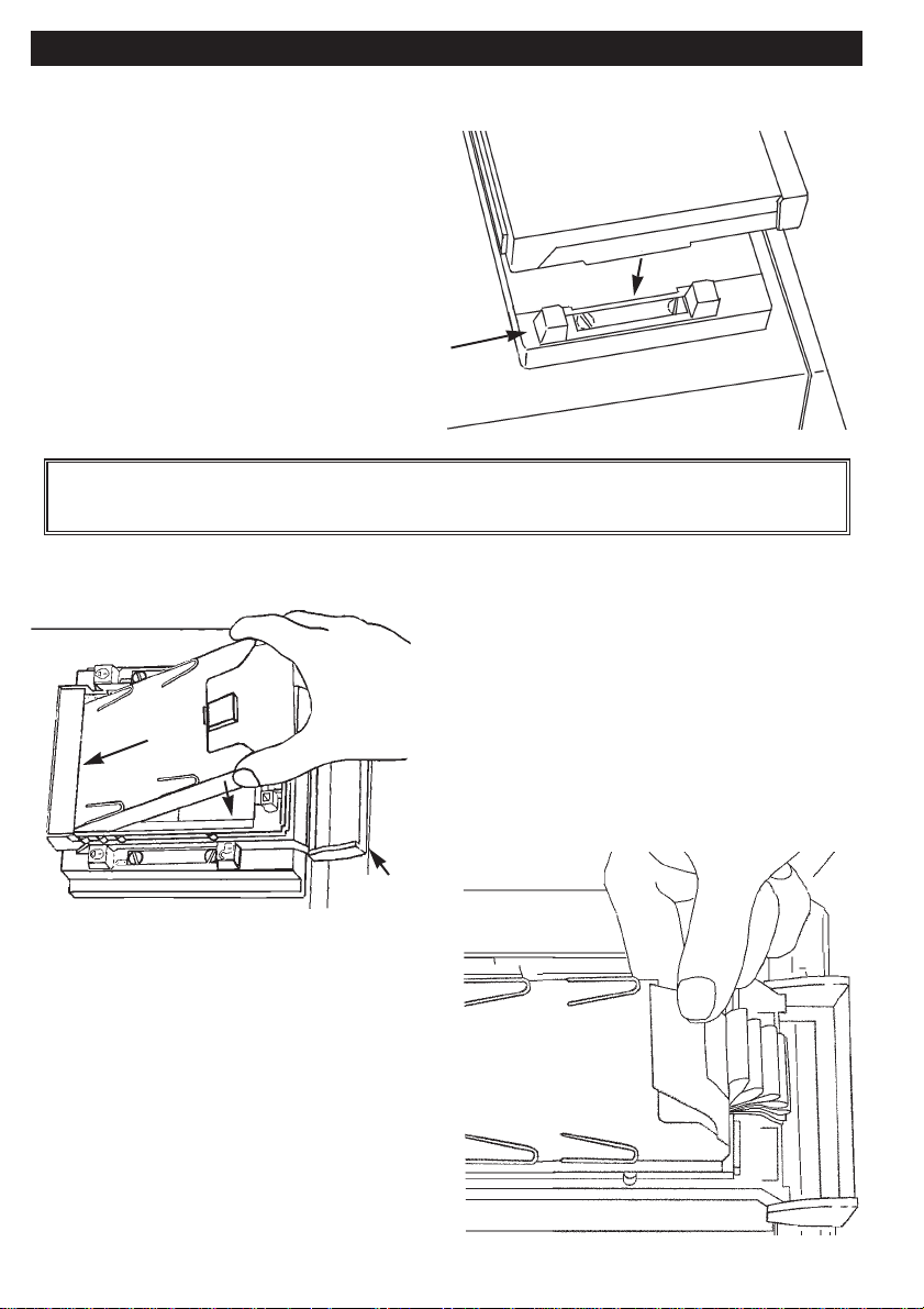
Attaching The Film Holder
a. Place the film holder on the
opening on the top of the printer
so that it’s retaining flanges align
with the locking mechanism (13)
on the printer.
b. Lock the film holder in place
by sliding both retaining bars in
the direction shown.
Loading A Fresh Film Pack
c. Use only Studio Polaroid colour
and / or Polapan Pro 100 black &
white film.
d. Open the film holder by pulling
down the ends of the latch and lifting
the cover.
e. Insert a fresh film pack into the
film holder as shown above with the
black paper tab facing you.
f. Check below the blac k tab to make
sure you see a number of white tabs
(one white tab is used for each film
exposure.)
55.. LLooaaddiinngg FFiillmm
latch
page 8 of 28
Important: The SP350 system is not designed for use with the
Thermoback or Thermobox product.
Page 9
g. Close the film holder making sure the black paper tab is outside the
film holder.
h. Pull the black
paper tab out of
the film holder,
keeping the tab
horizontal at all
times.
page 9 of 28
Important:
Be sure to remove the dark slide (22) before trying to take pictures.
Page 10

Lighting Set-Up
To obtain the best possible results from the SP350 system, it is
essential to set up studio lighting correctly. Using the lighting switch
(17) select the setting applicable to your studio set up. In set up, the
recommended minimum distance from subject to lens is 1.3m.
Strobe Lighting
When using strobe lighting, the ideal set up is with two lights positioned
as shown below. If you are using only one strobe light, it should be
positioned as close to the lens as possible (preferably directly above).
page 10 of 28
66.. LLiigghhttiinngg TTeecchhnniiqquueess
ensure strobe
lighting mode is
selected on the
printer front panel
Important: It is particularly important when using strobe lighting, to
ensure balanced lighting of the subject and the backdrop.If backdrop
lighting is used, it should be set to low power to a void over-exposing.
Saturating the backdrop may cause an imbalance in the video
image. For optimum results with either flood or strobe lighting, a grey
backdrop is recommended.
Page 11

If using the on board strobe
unit provided, insert the
batteries provided by
pressing the locking
knob and opening the
compartment cover as
shown opposite.
Place the batteries as illustrated in the
compartment and replace the compar tment
cover.
Tilt up the preview screen (1)
before sliding the on board
strobe unit on to the hot shoe
(2) as shown opposite.
Switch off the on
board strobe unit
when the camera is
not in use and remove
the batteries if you are not likely
to use for an extended period of time.
See on board strobe unit instructions for
further information.
Flood Lighting
When using flood lighting, the ideal set up is also with two lights
positioned as shown on the previous page . Ensure
flood lighting mode is selected on the printer front
panel as shown. If backdrop lighting is used,
ensure balanced lighting of the backdrop and the
subject.
page 11 of 28
Page 12

Exposure
Freeze an image by toggling the live / freeze button (5). If exposure
correction is needed see below
After correcting the exposure it is advisable to take a test picture as
there are differences between the preview screen image and the photo
image.
The printer allows you to make a number of choices. Set these before
capturing an image. The choices are as follows;
Strobe or flood light (17) - this allows you to match the SP350 system
to your studio lighting set up. This must be set before capturing an
image.
77.. PPrriinntteerr SSeettttiinnggss
If image is too dark
Use a larger lens aperture
or
Move lights closer to subject
or
Increase light output
If image is too light
Use a smaller lens aperture
or
Move lights away from subject
or
Decrease light output
page 12 of 28
strobe lighting mode for use
with on-board strobe unit or
external strobe lighting
flood lighting mode for use
with flood lighting
Page 13

1up, 2up, 4up, 5up, 6up or 9up print format (15) - this allows you to
specify whether your print will be a 1up, 2up, 4up, 5up, 6up or 9up
arrangement. The pr int format button (6) on the camera
performs the same function.
Film switch (17) - this switch has the same function as the film button
(8) on the camera and allows you to choose whether your image is
printed out on to colour or black & white film.
PC switch (14) - there is no support for this switch at present but in the
future it will allow you to link the printer to your PC and send images in
either direction i.e. download images from your PC to print or send
images to your PC from the camera for storage and /or manipulation.
page 13 of 28
1up
2up
4up
5up
6up
9up
Page 14

a. Check your customer’s image is correctly framed on the preview
screen (1). If using the on board strobe unit provided, ensure the ready
indicator shows red before capturing an image. This is easiest to view
with the preview screen in the lowered
position.
b. Press the blue live / freeze button (5) as
illustrated to capture the image.
c. If you or your customer are dissatisfied
with the image on screen, press the live /
freeze button (5) again and you will be returned to "live" mode.
d. Pressing the live / freeze button once more will capture another
image on the preview screen.
a. You must have a captured image on the preview screen in order to
print.
b. Be sure the dark slide (22) is removed
from the film holder before sending an
image to print.
c. With an image captured on screen, check the printer is in the desired
film mode and that the corresponding film is loaded.
d. Select a print arrangement using the print format switch (15) on the
printer or (6) on the camera.
e. To print, simply press either the print button (7) on the camera or the
print switch (21) on the printer. Printing takes 30-60 seconds during
which time the print indicator above the print switch (21) shows green.
page 14 of 28
88.. CCaappttuurriinngg TThhee CCuussttoommeerr’’ss IImmaaggee
99.. PPrriinnttiinngg TThhee CCaappttuurreedd IImmaaggee
dark slide
Page 15

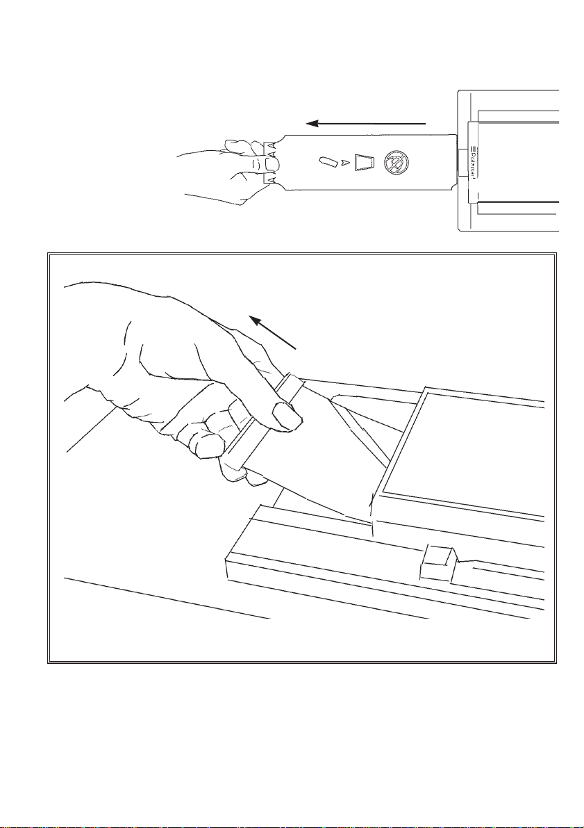
f. The printer beeps and the pull tab indicator (18)
flashes green indicating that the print cycle is
complete. Pull the white film tab keeping
it horizontal to ensure
that the film in the film
holder remains aligned.
g. Pull the tab marked with arrows straight out in one uninterrupted
motion as shown above. Lay the film down flat either on the printer or
the surrounding work surface.
h. The printer now starts counting the
development time of the film. As this
is the only picture currently
developing, it is film peel time
indicator 1 (19) that flashes for the
duration of the development period.
i. When the camera beeps and the film peel
time indicator (19) displays solid colour for 1
second, peel the back from the print as shown.
page 15 of 28
Important: The film uses a caustic paste. Avoid contact with skin,
eyes and mouth and keep away from children and animals.
If you get some paste on your skin, wipe it off immediately and
wash with water to avoid an alkali burn.
If eye or mouth contact occurs, quickly wash the area with plenty of
water and see a doctor. Keep discarded materials away from children, animals, clothing and furniture.
Page 16

The lens range markings can be used to focus the image if the subject
distance is known. For a more accurate setting:
a. Adjust lens aper ture to the maximum setting (f/1).
b. Adjust lighting to stop image saturation (e.g. switch off studio lights).
c. Move camera to correctly frame the subject on the preview screen.
d. Adjust the zoom lens to it’s most telephoto (highest magnification).
e. Focus lens on the subject.
f. Re-zoom to correctly frame the subject on the preview screen.
g. Return aperture setting and lighting to original configuration.
See below for the range within which the subject will remain in focus for
different aperture settings. This has been calculated for a nominal
camera to subject distance of 2m and a zoom setting which gives a
typical portrait shot. Different subject distances and zoom settings will
affect depth of field and so these values are intended as a guide only.
page 16 of 28
1111.. AApppprrooxxiimmaattee DDeepptthh OOff FFiieelldd
1100.. IImmpprroovviinngg TThhee FFooccuuss SSeettttiinngg
Important: It is recommended that the camera is operated in the
range of f/4 to f/8 to optimise the depth of field and maintain image
sharpness. Adjust studio lighting to achieve an f-number within this
range
F number
1
4
8
16
Min. Subject distance
1.95
1.80
1.65
1.40
Max. subject distance
2.05
2.25
2.60
3.85
Page 17

It is recommended that the brightness of the camera preview screen (1)
matches the brightness of the printed photograph. Use dial (10) to
adjust the brightness of the preview screen if necessary.
If you are not satisfied with the colour balance seen in your prints, you
need to check that the camera is calibrated to suit y our particular studio
set up. The camera colour balance has been factory preset to 3200K
for tungsten flood light and 5500K for strobe light. However lighting
used and personal preference will vary from one user to another
meaning fine adjustment may be necessary.
Camera Colour Calibration is split into two stages and must be carried
out in the following order:
1. Aperture Adjustment sets
the correct light level in the
video signal (prior to performing
the colour check) by adjusting
the lens aperture.
2. Colour Check allows
adjustment of the camera white
balance through fine adjustment of
the camera white balance controls.
1122.. DDiissppllaayy SSccrreeeenn AAddjjuussttmmeenntt
1133.. CCoolloouurr AAddjjuussttmmeenntt
page 17 of 28
lens aperture
white balance
controls
Page 18

To set up for calibration, make the following checks:
a. Ensure your lighting is set up as for normal operation (see section 5
for further details)
b. Calibration is best carried out with the camera mounted on a tripod
as shown below.
c. You will need the calibration overlay, grey card and colour adjuster
which are all packaged with the camera.
d. Position the grey card in the intended focal plane. This is easiest
achieved by seating the grey card as shown above. Note that the
recommended minimum distance from subject to lens is 1.3m.
e. Switch off the printer.
page 18 of 28
grey card
minimum 1.3m
Page 19

f. Peel back the securing tabs on
the calibration overlay and
position over the front panel of
the printer.
g. Ensure the the overlay is aligned
with the printer switches and press
the tabs to hold in place.
h. Reset the colour compensation
controls (30) on the rear panel of
the printer if they have been
adjusted at all. Align the slot on
each control with the horizontal
mark on the label as illustrated.
You are now ready to start camera colour calibration. To exit this
calibration mode, at any stage, simply switch off the printer.
Camera Colour Calibration Mode
a. To enter the calibration mode, hold
button 1
and
button 2
on the calibration overlay
down during power-up as shown.
The printer will sound a double
beep indicating that the
system is in Camera
Calibration Mode.
Also note that all
print option
indicators are
off.
page 19 of 28
colour compensation controls
Page 20

b. Press
button 3
on the calibration
overlay to select the lighting mode which
corresponds to your lighting set up.
Aperture Adjustment
c. Press
button 4
on the calibration overlay until
indicator A is lit as shown.
d. Zoom the camera in on the grey card by
turning the middle lens ring fully anti clockwise as shown. Ensure the grey card
fills the preview screen completely and
press
button 2
on the calibration overlay.
e.E, Fand Gindicate which direction to turn the lens aperture to
achieve the correct setting.Eindicates that there is insufficient light and
G
indicates too much light. Make a small adjustment of the lens
aperture (ring closest to camera body) in the direction shown according
to which indicator is lit.
f. Press
button 2
on the calibration overlay twice and look again at
indicators E, Fand G.
g. Repeat steps e and f until Flights
indicating that the light level is acceptable.
h. Fix the aperture at this point by tightening the locking screw. Check
that the aperture ring has not moved in tightening locking screw by
repeating steps f and g.
page 20 of 28
strobe
ambient
Important: Do not adjust the lens aperture and / or move the
position of the tripod during the following Colour Check procedure.
Page 21

Colour Check
i. Press
button 4
on the calibration overlay until
indicator Bis lit as shown.
j. Tilt the camera preview
screen up to gain access to
the four white balance
controls. Note that if you
are using strobe lighting
you will be adjusting C1
and D1 and if you are
using flood lighting you
will be adjusting C2
and D2.
k. Press
button 5
on the calibration overlay until indicator Clights on
the printer as shown.
l. With the camera still zoomed in on the grey card, freeze the image
by pressing
button 2
on the
calibration overlay twice.
m. If indicator Eis lit, make a
small clockwise adjustment
of C1 (for strobe) or C2
(flood) on the camera
using the colour adjuster as
shown. If indicator Gis lit,
turn C1 / C2 a fraction in the
anti-clockwise direction.
strobe ambient
(user
shown
turning C1 for
strobe lighting)
colour
adjuster
page 21 of 28
Page 22

n. Press
button 2
on the calibration overlay twice and look again at
indicators E, F, and G.
o. Repeat steps m and n until Flights.
p. Press
button 5
on the calibration overlay until indicator Dlights on
the printer as shown.
q. Press
button 2
on the calibration overlay twice.
r. If indicator Eis lit, make a small clockwise adjustment of D1 (strobe)
or D2 (flood) using the colour adjuster. If indicator Gis lit, make a small
anti-clockwise adjustment of D1 / D2.
s. Press
button 2
on the
calibration overlay twice and look
again at indicatorsE, F, and G.
t.. Repeat steps r and s until
F
lights.
u. Switch off the printer
and remove the calibration
overlay.
page 22 of 28
(user
shown turning
D1 for strobe lighting)
Important: If you have calibrated for strobe lighting mode you may
have to repeat the Colour Check process for flood lighting mode
since the preview liv e image seen on screen is in flood lighting mode.
Page 23

v. Switch on the printer, setup and print a test picture as you would in
normal use. The camera is calibrated to match your particular studio
lighting set up however you may wish to adjust the camera white
balance controls further to suit your own personal preference.
Alternatively adjustment of the Colour Compensation Controls (30)
can optimise printer performance to match film output. Note that these
controls do not alter the white balance of the camera in any way.
If you are still not satisfied with the colour balance of the prints, contact
your nearest Polaroid office for fur ther assistance.
Removing A Spent Film Pack:
a. Open the film holder.
b. Remove the empty film pack by
grasping it at the tab end, pulling it up and
lifting it out as shown opposite.
Removing the film holder
You do not have to remove the film holder to load film. However if you
are using two different film holders , for example, one for colour and one
for blac k & white film, y ou ma y need to
switch holders from time to time.
a. If there is film in the printer, a black
or white film tab shows. Insert the
dark slide (22) into the slot on the end
of the film holder, and slide it in until
the blue line is no longer visible. This
prevents the film from being exposed
when you remove the film holder.
1144.. FFiillmm
Important: Use only Studio Polaroid colour and Polapan Pro 100
black & white film.
page 23 of 28
Page 24

b. Unlock the film holder by
sliding the retaining bars (13), as
shown in the illustration opposite
and on the labels on the locks
themselves.
c. Remove the film holder by lifting it off the printer.
Cleaning the rollers
a. Open the door of the film
holder (12).
b. Remove the rollers by placing
your thumbs at the ends of the
roller assembly and rotating it
upwards.
c. While the rollers are out of the film holder wipe them gently with a
clean, lint free cloth moistened with water.
d. Replace the rollers by placing the
assembly against the film exit door
and rotating it downwards.
e. Check the film exit door and
remove any pieces of paper or dried
film developer.
f. Close the film holder and load film
as normal.
page 24 of 28
Important: Clean the rollers at the end of every pack of film.
Page 25

This troubleshoot should help you correct the most common problems
that you may encounter with the system. If the problem persists unplug
your unit and contact your nearest Polaroid office.
Symptoms
System will not power on
No image on camera
preview screen
System is powered up but
not responding
No image captured in
strobe mode
Nearly black or solid black
image
Green / yellow print
Checklist
Check all connections are made.
Check LED on power supply is on.
Check their is power to the system and
ensure connection to the printer is
correct. Check lens cap has been
removed and aperture opened. Adjust
brightness dial (10.)
Check the PC switch (14) is off.
Check on-board strobe unit is switched
on and seated correctly in hot shoe
(2). Check batteries have been
inserted in the correct or ientation.
Replace batteries if charging takes
longer than 60 seconds.
Check the dark slide has been
removed from the film holder before
printing. Check correct lighting mode
(17) has been selected.
Could be caused by trying to print a
black and white print on to colour film -
check film mode selected matches
loaded film.
page 25 of 28
1155.. TTrroouubblleesshhoooottiinngg
Page 26

Lens specification
Focal length 5.7 mm to 34.2 mm
Zoom 6:1. ratio
Aperture f/1 to f/16
Focus. 1.3m to infinity
Sensor specification
Image sensor resolution 752 by 582 pixels
Preview screen specification
PAL format composite video
3.8” display, 240 x 3 (RGB) x 130 pixels
Single tube, back lit, cold cathode fluorescent tube with diffuser
Adjustable viewing angle
Adjustable brightness
page 26 of 28
1166.. SSppeecciiffiiccaattiioonnss
Symptoms
Repeated white spots on
film
Curtain shaped mark or
streak on film
Undeveloped edges or
corners of film
Muddy looking print
Ver y light image or none at
all
Checklist
Caused by dirt on the film holder
rollers - clean rollers, see section 14.
Caused by hesitation during pulling of
film tab - always pull the tab out in one
uninterrupted motion.
Usually caused by pulling the film
tab out at an angle which prevents the
developer from spreading evenly over
the film.
Picture not developed long enough -
develop images for full time
recommended in the instructions.
Film has been greatly overexposed to
light.
Page 27

Polaroid warranties that this product complies with the following
directives :
89/336/EEC, 73/23/EEC, 93/68/EEC
Safety:
EN60950
EMC:
EN50081-1(1992)
EN55022(1994) Class B
EN500082-1(1998)
EN61000-4-2(1995)
EN61000-4-3(1996)
ENV50204(1995)
EN61000-4-4(1995)
EN61000-4-6(1996)
Since 1947, Polaroid has been the world's leading manufacturer of
instant imaging products for consumers and business alike. Over the
years, customer needs have changed, and so has the technology - but
the importance of high quality service has endured. As more and more
products are built with digital technology, and product downtime
becomes more and more critical, Polaroid has built a service
infrastructure to ensure a rapid response to any issues that you
encounter.
Polaroid always aims to produce products of the highest quality and to
support them with the ser vice you need to keep your business running
smoothly. Please contact your nearest Polaroid office for more
information.
1177.. EEMMCC SSttaatteemmeenntt ((EEuurrooppee))
page 27 of 28
1188.. SSPP335500 WWaarrrraannttyy // SSeerrvviiccee
Page 28

“Polaroid” and “Studio Polaroid” are registered trademarks of the Polaroid Corporation.
Printed in Great Britain. (V)PE3-350E-M-PB 05
English
As with any electrically operated equipment, basic safety
precautions should be observed. Remember:
1. Follow all instructions.
2. Do not leave unit unattended.
3. If unit will not be used for extended period of time
unplug from the electrical outlet.
4. Do not operate unit which has been dropped or
damaged, until it has been examined b y authorised service
centre.
5. Before storing, allow unit to cool completely.
6. To avoid electric shock hazards, do not immerse unit in
water or other fluids. Do not operate unit near water or
with wet hands. If service or repair work is required,
contact authorised service centre. Incorrect re-assembly
can cause shock when unit is used subsequently.
7. Close super vision is necessar y when unit is used by or
near children.
8. The use of accessories other than those recommended
may cause risk of fire, electric shock or injury.
PLEASE KEEP THESE INSTRUCTIONS.
 Loading...