

Page 1

User Manual
P75
© 2000 POLAROID
Page 2

FFOORREEWWOORRDD
This manual contains installation and operation information for the Polaroid 75 Series card printers
manufactured by Polaroid Corporation.
RREETTUURRNN MMAATTEERRIIAALLSS AAUUTTHHOORRIIZZAATTIIOONN
Before returning any equipment (camera or printer) to Polaroid Corporation for in-warranty or outof-warranty repair, contact Repair Administration for a Return Materials Authorization (RMA) number. Repack the equipment in the original packing material and mark the RMA number clearly on
the outside. Ship the equipment, freight prepaid, to the address given to you by Repair
Administration.
CCOOPPYYRRIIGGHHTT NNOOTTIICCEE
This document contains information proprietary to
the information contained within is copyrighted by
cated in full or in part by any person without written approval from
has been made to keep the information contained within current and accurate as of the date
of publication, no guarantee is given or implied that the document is error-free or that it is accurate with regard to any specification.
pose of product improvement, at any time.
Polaroid
Polaroid Corporation
Polaroid Corporation
reserves the right to make changes, for the pur-
. This document and
and may not be dupli-
Polaroid
. While every effort
TTRRAADDEEMMAARRKKSS
Polaroid 75 is a pending service mark. Polaroid is a registred trademark of Polaroid
Corporation, Cambridge, MA. All other trademarks or registered trademarks are marks of their
respective holders.
iii
Page 3
WWAARRRRAANNTTYY IINNFFOORRMMAATTIIOONN
WE NEED TO HEAR FROM YOU!
To establish Your Warranty Period And Provide Access To Technical Support, Send Us your
Warranty Registration Card Today!
Polaroid warrants the mechanism, control electronics and power supply, under normal use and service, to be free from defects in material and workmanship for a period of twelve (12) months from
the date of purchase by the end user. Polaroid warrants the print head, under normal use and service, to be free from defects in material and workmanship for a period of twelve (12) months from
the date of purchase by the end user. Proof of purchase is required. If proof of purchase cannot be
established, shipment date to the original buyer (dealer or distributor) will be used to establish the
warranty period.
Failure to exercise caution to protect the equipment from electrostatic discharge damage, adverse
temperature and humidity conditions or physical abuse, including, but not limited to, improper packaging, shipping, service or repairs performed by personnel not authorized by Polaroid may void the
warranty. Failure to use only Polaroid approved media may void the warranty.
Polaroid will, at its option, repair or replace the equipment or any parts which are determined to be
defective within this warranty period, and which are returned to Polaroid.
The warranty set forth above is exclusive and no other warranty, whether written or oral, is
expressed or implied. Polaroid specifically disclaims the implied warranties of merchantability and
fitness for a particular purpose.
DDEECCLLAARRAATTIIOONNSS OOFF CCOONNFFOORRMMIITTYY
EEuurrooppeeaann CCoouunncciill DDiirreeccttiivvee
89/336/EEC
modified by
92/31/EEC and
93/63/EEC
73/23/EEC modified
by 93/68/EEC
Model: P75
conforms to the following specification:
EMC Directive
EMC Directive
Low voltage
Directive
CCoommpplliiaannccee ttoo SSttaannddaarrddss
EN 55022-B
EN 500082-1,
1992
EN 60950 Product Safety
RF Emissions
control
Immunity to
Electromagnetic
Disturbances
FCC Part 15, Subpart A, Section 15.107(a) and Section 15.109(a) Class
A digital device
Supplemental Information:
This device complies with Part 15 of the FCC Rules. Operation is subject to the following Two
Conditions: (1) This device may not cause harmful interference , and (2) this device must
accept any interference received, including interference that may cause undesired operation.
Note:
This equipment has been tested and found to comply with the limits for a class A digital device,
pursuant to Part 15 of the FCC Rules. These limits are designed to provide reasonable protection against harmfull interference when the equipment is operated in a commercial environment. This equipment generates, uses, and can radiate radio frequency energy and, if not
installed and used in accordance with the instruction manual, may cause harmfull interference
to radio communications. Operation of this equipment in a residential area is likely to cause
harmfull interference in which case the user will be required to correct the interference at his
own expense.
IINNDDUUSSTTRRYY CCAANNAADDAA NNOOTTIICCEE
This device complies with Industry Canada ICS-003 class A requirements.
Cet équipement est conforme à l'ICS-003 classe A de la Norme Industrielle Canadienne.
iv
Page 4
IINNTTRROODDUUCCTTIIOONN
P75
Thank you for choosing the P75 Plastic Card Printer.
These printers produce cards ideal for personalised identification, access
control, visitor, membership, promotion and luggage card, badges and
tags.
This manual guides you to an efficient start up and operation of your new
Card Printer.
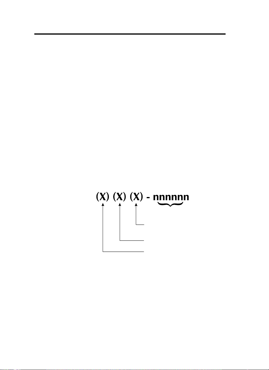
PP7755 PPRRIINNTTEERR MMOODDEELLSS
Polaroid
The
Here is a quick review of the Polaroid Card Printer Series numbering and
lettering system to help you.
The P75 Plastic Card Printer employs Dye Sublimation and Resin Thermal
Transfer technologies. Model numbers include identifiers that specify options
are shown using the following lettering conventions:
This information can be found on the printer serial number panel and is also
shown on the test card.
Product Number tells a story:
Serial Number
M
: Magnetic
Encoding
E
: Smart Card
C
: Color
}
Optional
v
Page 5
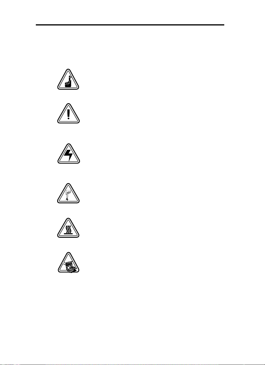
IICCOONNSS
Throughout this manual, different icons highlight important information, as follows:
Important general information
Mechanical hazard, such as one associated with moving
parts, capable of resulting in equipment damage or per-
sonal injury.
Electrical hazard, such as an exposed voltage point,
capable of causing electrical shock and personal injury.
An area where electrostatic discharge (ESD) can cause
component damage. Use a grounding wrist band.
Elevated temperature hazard, capable of producing a
burn.
Keep Card Printer clean by minimizing cover open
time.
vi
Page 6

TTaabbllee ooff CCoonntteennttss
1. GETTING STARTED
UNPACKING YOUR CARD PRINTER
INDICATORS AND CONTROLS
PRINTER INSTALLATION
2. OPERATION .............................................................................. 2.1
P75 PRINTER FEATURES
LOADING RIBBONS
LOADING CARDS
INSTALL CARD CLEANING CARTRIDGE
FEEDING ONE CARD AT A TIME
REMOVING CARD CARTRIDGE
PRINTING A TEST CARD
PRINTER MENU INFORMATION
3. STARTING TO PRINT CARDS.................................................... 3.1
4. CLEANING ................................................................................ 4.1
CLEANING SYSTEM .................................................................. 4.2
CLEANING THE PRINT HEAD
CARD CLEANING CARTRIDGE
5. TROUBLESHOOTING ................................................................ 5.1
6. TECHNICAL SPECIFICATIONS .................................................. 6.1
APPENDIX A - MAGNETIC CARD STRIPE ENCODER .................... A.1
........................................................................
...................................... 1.1
................................................ 1.3
.......................................................... 1.4
.......................................................... 2.1
.................................................................. 2.2
...................................................................... 2.4
................................ 2.5
............................................ 2.7
.............................................. 2.7
.......................................................... 2.8
.............................................. 2.9
.................................................. 4.3
................................................ 4.4
1.1
APPENDIX B - SMART CARD CONTACT STATION ...................... B.1
INTRODUCTION ........................................................................ B.1
APPENDIX C - ACCESSORIES & SUPPLIES .................................. C.1
RIBBONS
CARDS
ACCESSORIES
.................................................................................... C.1
........................................................................................ C.2
............................................................................ C.3
vii
Page 7

1
GETTING STARTED
UUNNPPAACCKKIINNGG
YYOOUURR CCAARRDD
PPRRIINNTTEERR
Your P75 printer ships in a carton and protective
anti-static bag. Keep all packing material in case
you need to move or re-ship the printer.
While unpacking, inspect the carton to ensure
that no damage occured during shipping.
Please ensure that you have a clean and nearly
dust free environment for proper operation and
storage of the printer.
1.1
Page 8
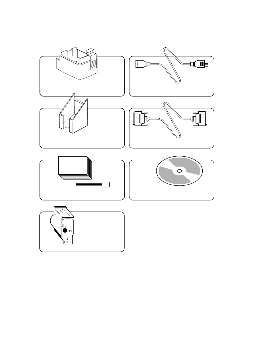
In addition to user documentation, make sure the
following items are included with your P75 printer:
CARD CARTRIDGE POWER CABLE
CARD OUTPUT HOPPER INTERFACE CABLE
SWABS & SATURATED CLEANING CARDS
CLEANING CARTRIDGE
If any items are missing, please contact your dealer.
To reorder, please refer to Appendix C of this
manual.
1.2
PRINTER DRIVER DISK
Page 9
IINNDDIICCAATTOORRSS
AANNDD CCOONNTTRROOLLSS
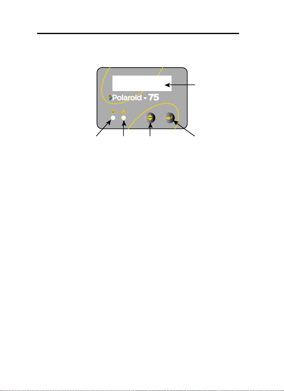
Your P75 printer has an LCD Display, two LED's
and two panel buttons.
LCD Display
LLCCDD DDiissppllaayy ::
LLEEDD''ss ::
PPAANNEELL
BBUUTTTTOONNSS::
Power
LED
Alert
LED
Menu
Button
Clear Button
[Select]
[Next]
TThhee 1166 cchhaarraacctteerr LLCCDD DDiissppllaayy iiss uusseedd ffoorr ::
- Showing the printer's current status
- Providing operator and service messages (Chapter 5)
TThhee ttwwoo LLEEDD''ss aarree uusseedd ffoorr ::
- Green: Power LED
- Amber: Alert LED (with beeper)
This Alert LED is on when an error condition exists.
The Beeper will sound three alert "Beeps" and the
LCD Display will show the associated error message.
TThhee MMeennuu BBuuttttoonn ((lleefftt)) iiss aa ppuusshh bbuuttttoonn uusseedd ffoorr::
- bringing printer into Menu Mode when pressed with
the printer showing READY on the LCD Display.
- using in Menu Mode to scroll through Menu Options.
TThhee CClleeaarr BBuuttttoonn ((rriigghhtt)) iiss aa ppuusshh bbuuttttoonn uusseedd ffoorr::
- clearing an error status (when LCD Display shows
an error report and Alert LED is on).
- invoking automatic retry of the operation which gave
the error.
NOTE: the buttons beep when pressed
1.3
Page 10
PPRRIINNTTEERR
IINNSSTTAALLLLAATTIIOONN
The following will guide you through the
installation of your
P75 printer.
CCAAUUTTIIOONN ::
Limit AC power supplied to the P75
Printer to 110 - 230 V AC, 60 - 50 Hz for an
associated 800 mA - 400 mA. Limit excess current
draw to 16 amps or less, using an associated
circuit breaker or other such device. Never operate
the printer in a location where operator, computer,
or printer can get wet. Personal injury could result.
The printer must be connected to an earthed
electrical power supply and properly protected
against electrical surges and grounding faults.
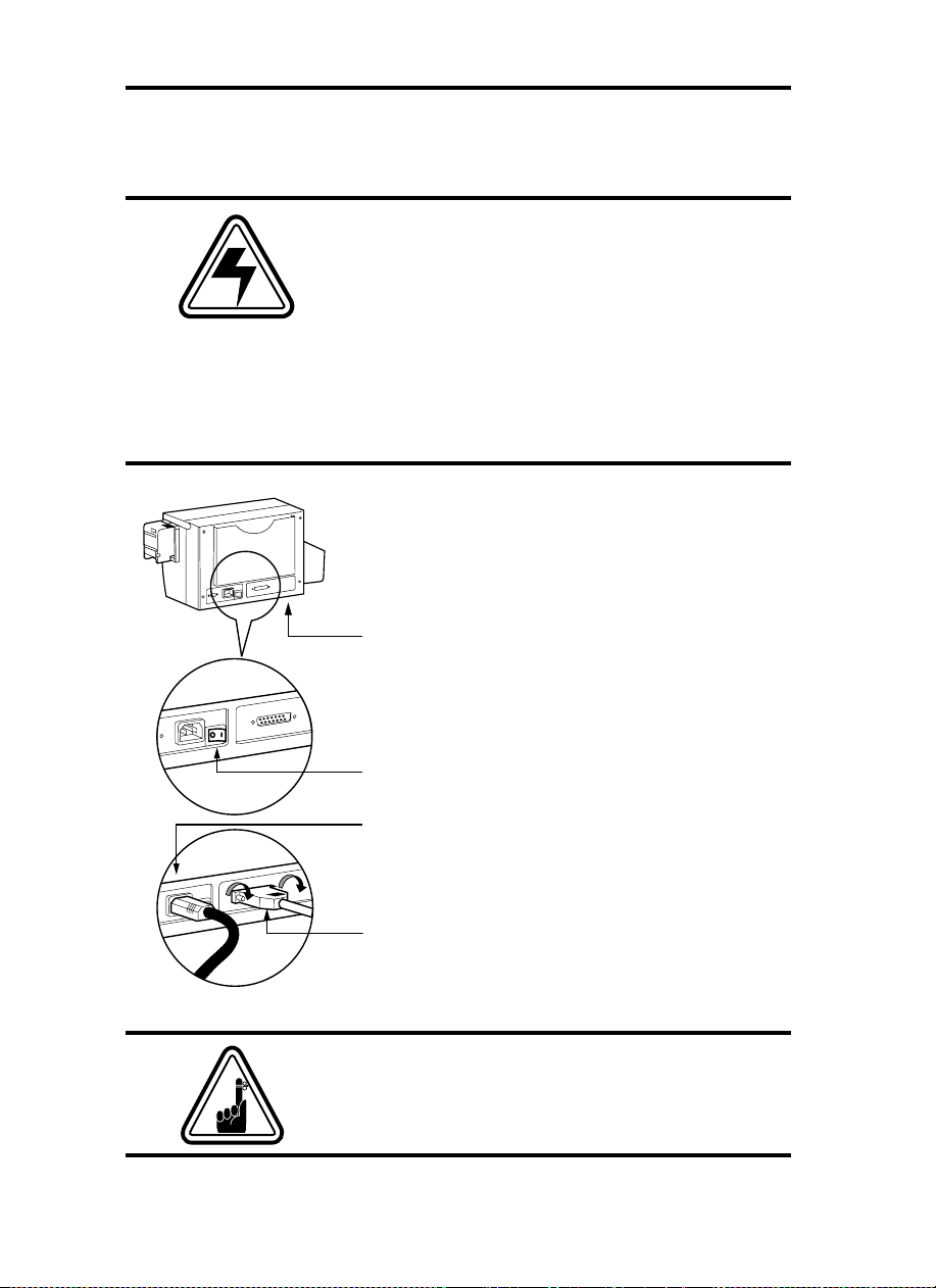
1.
Place the printer in a location that allows easy
access to all sides. The printer should never be
operated while resting on its side or upside
down.
2.
Place the printer’s power switch in the OFF (0)
position.
3.
Insert the power cable to the printer power socket
and attach to grounded electrical socket of the
proper voltage and type.
1.4
4.
Attach interface cable to printer and computer
and then secure.
5.
Switch power on.
CCAAUUTTIIOONN::
Intermittent or unpredictable
operation may occur from unsecured connectors.
If damaged, the power cable must be replaced by
an exact equivalent.
Page 11
2
8
5
7
B
2
A
4
1
3
6
9
OPERATION
PP7755 PPRRIINNTTEERR
FFEEAATTUURREESS
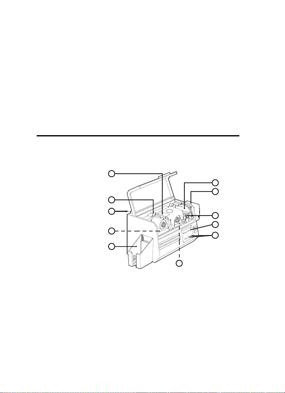
PLEASE NOTE : Any blue items inside the printer can be operated by the user.
STANDARD FEATURES
1. Print Head
2. Print Head Unlock lever
3. Card Output Hopper
OPTIONAL FEATURES
A. Magnetic Encoder Station
B. Smart Card Contact Station
The following shows the features found on
your P75 Printer:
4. LCD Display
5. Panel Button LED's
6. Card Cleaning Cartridge
7. Card Cartridge
2.1
Page 12
LLOOAADDIINNGG
RRIIBBBBOONNSS
The P75 Printer requires approved ribbons
(See Appendix C). The Resin Thermal
Transfer and Dye Sublimation ribbons are
specifically designed for your P75 Printer.
For optimum performance and printer life
(Print Head), always use approved ribbons.
DO NOT TOUCH the print head or the
electronic components on the print head
carriage. Discharges of electrostatic energy
that accumulates on the surface of the human
body or other surfaces can damage the print
head and other electronic components used
in this device.
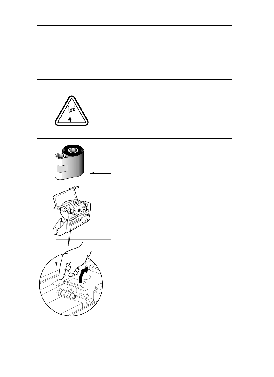
11..
Remove ribbon from packaging.
2.2
22..
With printer power on and READY
status, open cover and press down on
the Print Head Unlock Lever to open the
print head carriage. The print head
carriage will pop open.
Continued on next page ......
Page 13
SUPPLY SPINDLE
TAKE UP SPINDLE
`CLICK'
33..
Load ribbon onto the supply spindle
(under print head carriage) and empty
core (with tape attached) onto the takeup spindle. Make sure the ribbon comes
off the top of the supply spindle and
feeds to the top of the take-up spindle.
44..
Push down on the Print Head Lock
Lever until an audible 'click' signals the
locked-down position.
55..
Close Cover.
Please note that the ribbon automatically synchronises whenever the print head lock down occurs.
2.3
Page 14
LLOOAADDIINNGG CCAARRDDSS
'CLICK'
To help you load, print, and collect cards, the
P75 has the following items:
AA -- CCAARRDD CCAARRTTRRIIDDGGEE
For loading cards
11..
Install Card Cartridge by hooking onto
printer as shown and clicking down.
22..
Install cards into Cartridge.
*
DO NOT bend cards or touch print surfaces
as this can reduce print quality. The surface
of the cards must remain clean and dust free.
Always store cards in an enclosed container.
Ideally, use cards as soon as possible. If cards
stick together, carefully shuffle
them.
33..
Close Cartridge.
* See Chapter 6, Technical Specifications, for card requirements and capacities.
2.4
Page 15

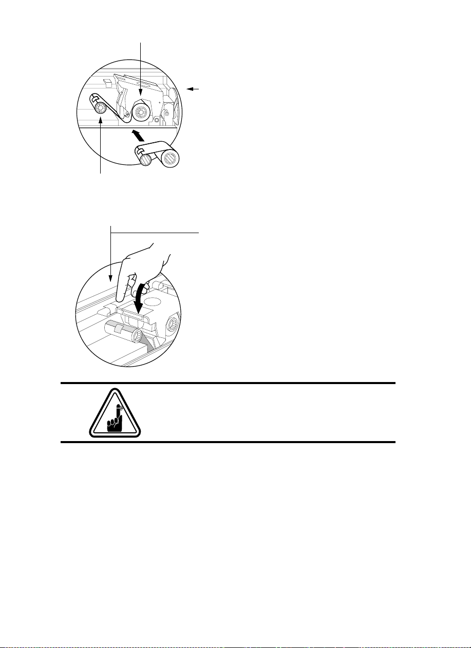
BB -- IINNSSTTAALLLL CCLLEEAANNIINNGG CCAARRTTRRIIDDGGEE
This item is used to clean the cards entering
the printer.
11..
Remove Card Cleaning Cartridge from
packaging.
22..
Open Printer cover and locate Cleaning
Cartridge place.
Remove the yellow adhesive.
3.
Make sure the arrow on top of the assembly
is facing toward the rear of the printer.
Hook assembly into slot on printer and rotate
down.
Ensure the assembly locks in place.
2.5
Page 16

This item is operated by the user to prevent
more than one card feeding into the printer
at the same time and causing a jam.
Open Cover, and adjust lever to correct
position. Repeat for different card thickness.
(Factory setting is for 30mil (0.762 mm) card
thickness. See diagram below :
CCaarrdd tthhiicckknneessss::
A - 60mil (1.524mm) to 50mil (1.27mm)
B - 40mil (1.016mm)
C - 30mil (0.762mm)
D - 20mil (0.508mm)
E* - Less than 20mil (0.508mm)
* Start at lowest position and move lever up to
match card thickness.
For other card thickness, start lever at lowest
position and move up until cards feed.
CC -- CCAARRDD TTHHIICCKKNNEESSSS CCOONNTTRROOLL LLEEVVEERR
2.6
DD -- CCAARRDD OOUUTTPPUUTT HHOOPPPPEERR
For collecting printed cards.
Install Card Output Hopper onto printer by
hooking over bottom edge of card exit
aperture.
Page 17

FFEEEEDDIINNGG OONNEE
CCAARRDD AATT AA TTIIMMEE
A Manual Feed Slot is available on the side of the
Card Input Hopper for feeding single cards.
Cleaning Cards are fed manually through this
slot. The Card Cartridge must be empty
manual card feeding to work properly.
For one-at-a-time printing, feed cards
through slot on side of Hopper.
Do not feed more than one card at a time.
for
RREEMMOOVVIINNGG CCAARRDD
CCAARRTTRRIIDDGGEE
HOOK
Remove the Card Cartridge prior to
packaging the printer for shipment.
To remove, pull hook back, and lift hopper
out.
2.7
Page 18

PPRRIINNTTIINNGG AA TTEESSTT
CCAARRDD
With ribbon and cards loaded, your P75 printer
is ready to print. To check the operation of the
printer you should print a test card.
11..
Place the printer's power switch in the
OFF (0) position.
22..
While pressing the right panel button,
switch printer on. LCD screen will show
'SELF TEST'
33..
Release button once 'SELF TEST' is
displayed on LCD screen.
44..
A test card will print after a few seconds.
LCD display will show printing status.
2.8
This is an example of the test card.
Page 19

PRINTER MENU
INFORMATION
The printer is equipped with a LCD Display which gives
access to different menus.
Menu key moves from
pressing the
Menu
READY
Button :
Status into the Main Menu by
Menu Button
[NEXT]
The top line display shows menu information. The second line of display clarifies the function
of the two [NEXT] and [SELECT] press buttons relative to the current menu item.
Clear Button
[SELECT]
2.9
Page 20

PRINTER INFO
CLEANING
PPrriinntteerr MMooddeell NNuummbbeerr
PPrriinntteerr FFiirrmmwwaarree VVeerrssiioonn
NNuummbbeerr ooff iimmpprreessssiioonnss
GGOO TTOO MMAAIINN MMEENNUU
CCLLEEAANN PPRRIINNTT HHEEAADD
To clean the Thermal Print
Head and card transport system
CCLLEEAANN MMAAGG..HHEEAADD
To clean the magnetic
Encoder Head
GGOO TTOO MMAAIINN MMEENNUU
READY
SELF TEST
PRINTER DEFAULTS
TTEESSTT PPAATTEERRNN
To print a printer test card
PPRRIINNTT PPAARRAAMMEETTEERRSS
To print a test card showing
the operating parameter settings of the printers
MMAAGG -- PPAARRAAMMEETTEERRSS
To print a test card showing the operating
parameter settings of magnetic encoder.
GGOO TTOO MMAAIINN MMEENNUU
RRiibbbboonn ttyyppee
To show the type of ribbon installed.
It may not match the ribbon physically installed
until the installed ribbon has been selected
through the driver
OOffffsseett XX:: aaaa--YY::bbbb
To show the X print location offset
value in pixels (aa)
To show the Y print location offset
value in pixels (bb)
MMaagg.. OOppttiioonn:: cccccccc
To show the setting of the magnetic
encoder as (cccc), which can be:
- HICO (high coercivity)
- LOCO (low coercivity)
- NONE (no encoder present)
CCoolloorr PPaarraammeetteerrss
To show the intensity values of Yellow (Y),
Magenta (M) and Cyan (C) panels and contrast
value of Black Resin (K) Panel.
2.10
GGOO TTOO MMAAIINN MMEENNUU
Page 21

3
STARTING TO PRINT CARDS
Printing with the P75 Printer requires the
Windows printer driver, the Windows ID
Card Maker application software package or
printer command level programming
through the printer interface.
The P75 Card Printer can be used with any
Windows 95/98 and Windows NT 4.0
software application program, using the
drivers provided with the printer.
This section contains information on the
printing of a sample card in color
(using the 5-Panel color ribbon YMCKO)
and the Windows printer driver.
BBEEFFOORREE
versions, always delete the existing printer driver
version from your computer.
installing updated printer driver
3.1
Page 22

TO INSTALL THE P75 PRINTER DRIVER IN WINDOWS 95/98, USE THE
FOLLOWING STEPS:
IMPORTANT NOTE
STANDARD MODE AND ALSO ENSURE THAT YOU HAVE DELETED ANY
PREVIOUS VERSIONS OF THIS PRINTER DRIVER. IF YOU HAVE ANY DOUBTS
PLEASE CONTACT YOUR IT DEPARTMENT
This installation uses floppy drive 'A' as the installation drive with the printer used as
stand alone.
1.
Start your computer and then Windows.
2.
Insert your 'POLAROID Software' diskette into the drive 'A'.
3.
Under Windows click the
4.
Double click on the
5.
6.
7.
8.
The Printer Wizard will copy the necessary files to the PC for you and the P75 printer
driver installation will be completed.
Local Printer
Ensure
Click on
P75 CARD PRINTER should be displayed after which click on Next.
Choose
Printer
Have Disk
LPT1 : ECP Printer Port
and click on
- ENSURE THAT YOUR PC PRINTER PORT IS SET TO
.
Start
button, select
Add Printer icon
is selected and click on Next.
and then type in '
Finish
to install.
and also Next.
, click on
Settings
A:\win95
Next
Printers
, then
' and click OK.
, select
Yes
.
to set as
Default
TTOO IINNSSTTAALLLL TTHHEE PP7755 PPRRIINNTTEERR DDRRIIVVEERR IINN WWIINNDDOOWWSS NNTT44..00::
Ensure that you have administrative privileges to perform this installation or contact
your IT department.
Set printer as
Use the steps provided for Windows 95/98 installation with the exception of
where you must type in '
NNoott SShhaarreedd
for stand alone use.
AA::\\nntt4400
' instead and click OK.
sstteepp 66
3.2
.
Page 23

Once the printer driver has been successfully installed, you will need to configure it
for your printer. This driver provides control of several printer features when printing
from Windows applications. These features are accessed through the P75 Plastic
Card Printer
Printers
in
The P75 Printer screen appears. Change the options as follows:
Properties
. Then click
. To access these properties select the
File
Menu and select
Properties
P75 Card Printer
.
icon
1.
On the
equipped with a Magnetic Encoder option, select
option.
2.
On the
Landscape or Portrait - Select '
3.
On the
5-panel ribbon.
4.
In the same tab, go to
the text printing using the Black Resin Panel from the Color Ribbon.
5.
Close the POLAROID 75 Printer Properties screen.
Now that you have loaded media and set up the printer driver, the P75 Printer is
ready to print.
EXAMPLE: FOLLOW THESE STEPS TO PRINT YOUR FIRST CARD:
1.
Go to the microsoft Word Software.
2.
If the printer was not selected as the default printer, go to the
select
Close
Printer Tab
Card Tab
Ribbon Tab
Print
and choose
the print dialog box.
configure the magnetic encoder feature. If your printer is
select card orientation:
, select the Ribbon Type. Select
Black Panel
Polaroid 75 Card Printer
Landscape
area and select
With Magnetic Encoder
'.
YMCKO
Text Only
in the printer names list. Then
. This option allows
for the standard
file
menu and
3.
Come back to
4.
Select
orientation: "landscape".
5.
Go to Margins Tab, put the top, Bottom, left- and right margins with O values.
6.
Press OK to close Page Setup Window.
7.
The card appears on the screen.
file
menu and choose
paper Size tab
and in
Page Setup
Paper Size
.
choose
Card
. Then select the
3.3
Page 24

8.
Design a card with both black and colored text and colored pictures,i.e.:
Symbols in color
Logo in Black
and White
Text in Red
Text in Black
9.
Once you are ready to print, go to
10.
The printer will feed in a card and start printing ( the data download time will
vary depending on the complexity of the card design and the processing speed
of your computer).
11.
Once the printing job is achieved the card is ejected from the printer.
File
and point
Print
3.4
Page 25

4
CLEANING
PROTECT YOUR FACTORY WARRANTY !
The recommended maintenance procedures must
be performed to maintain your factory warranty.
Other than the recommended cleaning procedures
described in this manual, allow only
authorised technicians to service the P75 Printer.
NNEEVVEERR
or cable inside the printer.
NNEEVVEERR
remove particles in the printer.
loosen, tighten, adjust, or bend, etc. a part
use a high pressure air compressor to
Polaroid
4.1
Page 26

CCLLEEAANNIINNGG SSYYSSTTEEMM
Your P75 Printer includes a simple cleaning
system using the Pre-saturated Cleaning Cards
provided. The regular use of these cards will
clean and maintain important parts of your
printer: including the Print Head, and
Transport Rollers.
CLEAN PRINTER
WWHHEENN TTOO CCLLEEAANN
When LCD screen reports message.
HHOOWW TTOO CCLLEEAANN
11..
Leave power on.
Open Cover and release Print Head Bracket
to remove ribbon.
Close Print Head.
Close Cover. Remove cards from Card
Cartridge.
22..
Insert one Pre-saturated Cleaning Card
(provided) through slot on the side of the Card
Cartridge.
33..
Press the Clear Panel Button (right) for a
few seconds. The card will feed into printer
and carry out the cleaning process. Repeat
the process with a new Cleaning Card if
necessary.
Notte:
For cleaning prior to the WHEN TO CLEAN signal, press the Right Panel
Button for 3 seconds to start the cleaning process (Repeat first steps 1 and 2 above).
4.2
Although the CLEAN PRINTER message is
displayed until the cleaning process has been
performed, the printer will continue to operate.
Page 27

CCLLEEAANNIINNGG TTHHEE
PPRRIINNTT HHEEAADD
A cleaning using the Cleaning Cards usually
suffices. However, a separate Print Head
cleaning using swabs can remove more stubborn
deposits when print anomalies persist. To avoid
deposits, only use foam-tipped swabs.
11..
Raise Print Head and remove the
Ribbon.
22..
Clean Print Head by moving alcoholmoistened swab tip side-to-side across
Print Head elements. Only use
moderate force.
(To reorder swabs see Appendix C).
Never use a sharp object to scrape deposits
from the print head. Permanent damage
will result.
4.3
Page 28

CCAARRDD CCLLEEAANNIINNGG
CCAARRTTRRIIDDGGEE
Your P75 Printer also has a Card Cleaning
Cartridge. This item cleans the cards entering the
printer. To ensure print quality, the cleaning
roller requires periodic replacements.
CLEAN PRINTER
WWHHEENN TTOO MMAAIINNTTAAIINN
When LCD screen reports message.
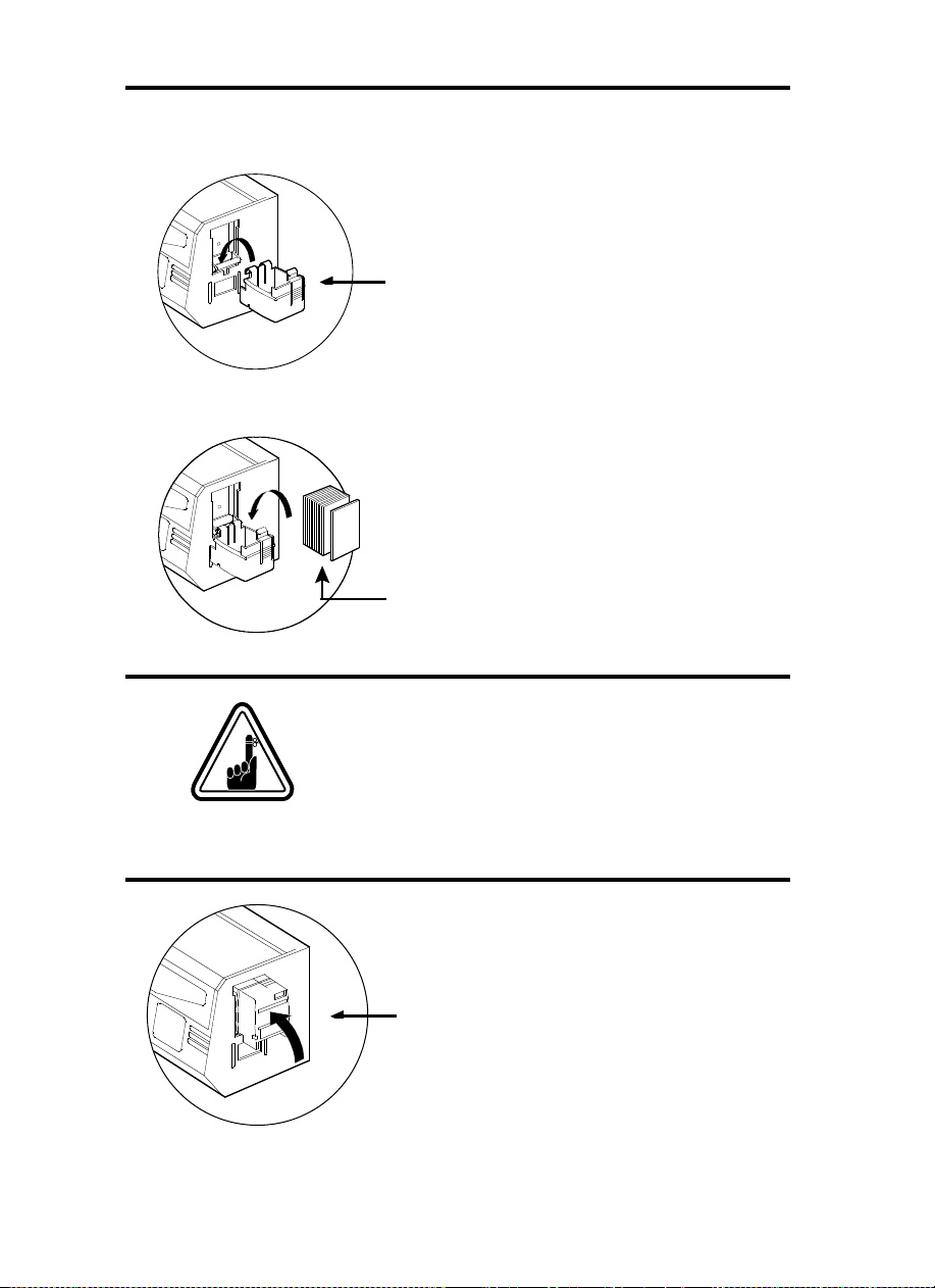
HHOOWW TTOO MMAAIINNTTAAIINN
11..
Open Cover and locate Cleaning
Cartridge.
22..
Gently remove Cleaning Cartridge by
rotating up and away from printer.
4.4
Continued on next page ....
Page 29

SLOT
33..
Remove Cleaning Roller from Cartridge
and discard.
44..
Install new Cleaning Roller into
Cartridge*. To avoid contamination, always
hold the Cleaning Roller assembly by the
ends.
55..
Carefully peel off wrapper from new
Cleaning Roller while in Cartridge.
66..
To replace Cartridge into printer: Make
sure the arrow on top of the assembly is
facing toward the rear of the printer. Hook
assembly into slot on printer and rotate
down. Ensure the assembly locks in place.
DO NOT touch the roller surface that
contacts the cards.
77..
Close Cover
* See Appendix C for replacement Cleaning
Rollers.
Although the CLEAN PRINTER message is
displayed until maintenance has been
performed, the printer will continue to operate.
4.5
Page 30

TROUBLESHOOTING
This section offers solutions to potential problems
you may experience with your P75 printer. The
table below lists the screen messages that will be
displayed on the printer's LCD, both during
normal operation and to alert operator of any
error conditions. There is also some additional
information dealing with quality issues concerning
printing onto cards.
SSCCRREEEENN MMEESSSSAAGGEE MMEEAANNIINNGG AACCTTIIOONN
INITIALISING
The printer is performing an
internal test before use
Wait for the ready message
5
READY
PRINTING
WAIT
TEMPERATURE
ON LINE
SELF TEST
DOWNLOADING
DATA
PRINTING YELLOW
5.1
Ready for use
Card printing in progress
The printer is warming up
Waiting for host data
Self test card printing
The card data is being
transmitted
The yellow panel is printing
Please wait
Wait for READY message
Send card data
Wait for test card
Wait for card printing to start
Page 31

SSCCRREEEENN MMEESSSSAAGGEE AACCTTIIOONN
PRINTING MAGENTA
PRINTING CYAN
MMEEAANNIINNGG
The magenta panel is
printing
The cyan panel is printing
PRINTING BLACK
PRINTING VARNISH
PRINT
HOLOGRAM
MOVING CARD
CLEAN PRINTER
CLEANING
REMOVE RIBBON
OUT OF RIBBON
MECHANICAL
ERROR
OUT OF CARD
HEAD OPEN
COMMAND ERROR
The black panel is printing
The overlay is printing
A hologram overlay is
printing
The card is being transported
The printer is prompting
operator maintenance
The printer is performing an
internal cleaning routine
The ribbon has not been
removed whilst the cleaning
operation is in progress
The printer ribbon has run
out
The printer has an error
moving the card internally
The card feeder is empty
The print head is not locked
into position
The data being sent from the
host is not recognised
Carry out the cleaning
procedure as detailed in
section 4 of this manual
Remove ribbon
Replace printer ribbon
Remove the jammed card.
Ensure that the card is not
out of specification
Add more cards or adjust the
card feeder to accept the
cards
Lock the print head in its
lower position
Check that the data is
suitable for printing. Try reprinting a card from known
'good' data
PARAMETERS
ERROR
The features of the card are
not recognised
Check the Windows driver
options and printer type
5.2
Page 32

SSCCRREEEENN MMEESSSSAAGGEE MMEEAANNIINNGG AACCTTIIOONN
ENCODING ERROR
Data cannot be written or
read from the card's magnetic
stripe
Check that the cards are
loaded with the magnetic
stripe in the correct
orientation. Check whether
high or low coercivity cards
have been specified. Check
that the data conforms to ISO
specifications. See Appendix
A of this manual for further
information.
MAGNETIC ERROR
The printer cannot detect a
magnetic stripe on the card.
Check the card orientation
BLANK TRACK
FLASH ERROR
NO ACCESS
RRiibbbboonn EErrrroorrss::
Check that the print ribbon has not 'run out'. Lock and then
Contact your dealer for
technical support.
unlock the print head assembly; this resynchronises the ribbon
automatically. When using a color ribbon, it should advance automatically so
that the leading edge of the Yellow panel is beneath the print head. Ensure
that the correct ribbon type has been specified in the Windows driver.
CCaarrdd FFeeeedd && MMeecchhaanniiccaall EErrrroorrss::
Ensure that the card thickness adjustment
has been set-up correctly to allow one card to feed.
MMaaggnneettiicc EEnnccooddiinngg EErrrroorrss::
Check that the cards are inserted correctly in the
printer. Ensure that the cards are low or high coercivity as required, and are
set-up correctly in the printer driver.
CClleeaanniinngg AAlleerrtt::
The printer has counted the number of cards printed and has
automatically flagged that a cleaning routine needs to be carried out. (See
Chapter 4).
5.2
Page 33

QQUUAALLIITTYY IISSSSUUEESS
MMiissssiinngg pprriinntt oorr wwhhiittee lliinneess::
ribbon is neatly winding onto the take-up core
and that no creases are visible on the used ribbon.
If there is a fine white line in the same place on
the card, this indicates possible print head
damage.
Ensure that the
PPoooorr PPrriinntt QQuuaalliittyy::
check that the printer is clean and dust free.
Check that the correct type of ribbon is being
used and is specified correctly in the Windows
driver. Ensure that the cards are clean and are not
covered by loose plastic particles. Do not try
reprinting previously printed cards as the ink will
not bond correctly to the card
MMiissssiinngg aarreeaass ooff pprriinntt::
flat and free from any surface depressions. The
cards and printer must be clean and not
contaminated by grease, dust or other particles.
Print a Self-Test card, and
Ensure that the cards are
5.3
Page 34

6
TECHNICAL SPECIFICATIONS
GGeenneerraall
CCoolloouurr PPrriinnttiinngg
• High speed printing, over 140 cards/hour edge to
edge in full color (YMCKO) throughput
• Small footprint
• Windows Drivers for 95/98 and NT 4.0 (option)
• One year printer warranty
• One year print head warranty
• Color dye sublimation or monochrome thermal
transfer printing
• 25 seconds per card edge to edge in full color
(YMCKO)
• 300 dpi (11.8 dots/mm) print resolution
• Edge to edge printing standard
6.1
Page 35

FFoonnttss
• Resident: Arial Normal 100, Arial Bold 100
• True Type fonts available via Windows Driver
CCaarrddss**
• Types PVC, Composite
• Card width/length: ISO CR-80 - ISO 7810, 2.125”
(54mm) by 3.375” (86mm)
• Option: Magnetic Stripe - ISO 7811
• Option: Smart Card - ISO 7816-2
• Card thickness: 0.25mm to 1.524mm
• Card Cartridge capacity: Up to 210 cards 0.25mm),
up to 75 cards (0.15mm)
CARD DIMENSIONS
ISO STANDARD DIMENSIONS FOR PLAIN CARD
ISO STANDARD DIMENSIONS FOR MAGNETIC STRIPE CARD
CHIP POSITION FOR SMART CARD
ISO STANDARD AFNOR STANDARD
* Use Polaroid approved media only.
6.2
Page 36

RRiibbbboonnss**
• Monochrome: 1500 cards/roll
• Monochrome colors: black, red, blue, green, silver,
gold, white, Scratch-off gray
• K-resin + O: 800 cards/roll
• K-dye + O: 800 cards/roll
• YMCKO: 200 cards/roll
• YMCKO: 350 cards/roll
OOvveerrllaayy VVaarrnniisshh
IInntteerrffaacceess
MMeecchhaanniiccaall
EElleeccttrriiccaall
EEnnvviirroonnmmeennttaall
• Thermal transfer
• 4 microns thick
• Clear and holographic options:
- Clear
- Genuine/Secure Hologram
- Custom Hologram
• Parallel Standard (cable included)
• RS-232C Serial (option)
• Width: 329 mm†
• Depth: 219 mm†
• Height: 232 mm†
• Weight: 6.3 kg
• 110 ~ 230 Volts AC, 60 ~ 50 Hz
• FCC Class A, CE, UL, and CUL approved
• Operating Temperature: 60 to 86°F (15 to 30°C)
• Operating Humidity: 20 to 65% non condensing
• Storage Temperature: -23 to 158°F (-5 to 70°C)
• Storage Humidity: 20 to 70% non condensing
• Ventilation: Free air
* Thermal transfer (Resin) ribbons offer more durability
than dye sublimation, with greater resistance to
scratches and UV-induced fading.
6.3
Dye Sublimation printing requires dye sublimation ribbons, with either black or cyan, magenta, and yellow
(plus black resin) panels.
† Measured without card feeder and card hopper.
Page 37

OOppttiioonnss
• RS-232C serial port
• Smart Card Contact Station (0.76mm cards only)
• Magnetic Encoder (0.76mm cards only)
• Extended Warranty program
• Hot Swap Warranty program
• Cleaning supplies
• Service Manual
Use only Polaroid-approved card and ribbon
media. Using non-approved card or ribbon media
can void your warranty.
Refer to the Accessories section for more information about Card and Ribbon Media available
from Polaroid.
6.4
Page 38

APPENDIX A - MAGNETIC CARD STRIPE
ENCODER
Operation and maintenance requirements for the P75 Printer with the optional
magnetic card stripe encoder. (See Chapter 2 for location). The magnetic encoder
can be set for either high or low coercivity.
The magnetic encoder is a factory installed item with the
read/write head positioned below the card path, available
with HICO encoding or LOCO encoding.
When loading cards into the Card Cartridge, please ensure
that the magnetic stripe is facing towards the printer and
STRIPE
DOWN
STRIPE
UP
closest to the rear.
Also available are Printer models with the Magnetic
Read/Write head positioned above the card path, with
HICO encoding or LOCO encoding.
When loading cards, please ensure that the magnetic
stripe is facing away from the printer and closest to the
rear.
Approved HICO & LOCO PVC cards are available. (See Appendix C).
ONLY USE cards that comply with ISO 7810
& 7811 standards for magnetic stripe cards.
The magnetic stripe must be flush to the surface
of the card to work properly. Never use tapedon magnetic stripes.
A.1
Page 39

The read/write head requires periodic cleaning to maintain error-free encoding.
CLEAN PRINTER
Notte:
For cleaning prior to the WHEN TO CLEAN signal, press the
Right Panel Button for 3 seconds to start the cleaning process.
(repeat first steps 1 and 2 above)
WHEN TO CLEAN
When LCD screen reports message.
HOW TO CLEAN
1.
Leave power on.
Open Cover and release Print Head Bracket to
remove ribbon.
Close Print Head.
Close Cover. Remove cards from Card Cartridge.
2.
Insert one Pre-saturated Cleaning Card (provided) through slot on the side of the Card Cartridge.
3.
Press the Clear Panel Button (right ) for a few
seconds. The card will feed into printer and carry
out the cleaning process. Repeat the process with
a new Cleaning Card if necessary.
Although the CLEAN PRINTER message is
displayed until maintenance has been
performed, the printer will continue to
operate.
ISO STANDARD ENCODING
Track #
1^
2=
3=
*
Bit per inch
Field Separator
Track density Valid Characters
Alphanumeric
75BPI
*
*
*
(ASCII 20
Numeric
(ASCII 48
Numeric
(ASCII 48
∼95†)
∼62)
∼62)
210BPI
210BPI
# of characters
79‡
‡
40
‡
107
† Except the '?' character
‡ Including Start, Stop and LRC characters. Also note that these 3 characters are automatical-
ly managed by the magnetic encoder according to the ISO Standard Norms.
NOTE: Refer to the Card Printer Programmer's Manual for complete programming information.
A.2
Page 40

APPENDIX B - SMART CARD CONTACT
STATION
This section contains information on the additional
operations of the P75 Printers with Smart Card
Contact Stations. (See Chapter 2 for location.)
IINNTTRROODDUUCCTTIIOONN
Smart Cards can have a built-in microcomputer and
a battery. Card Memory can store fingerprints, voice
recognition patterns, medical records and other
such data. The P75 may be equipped with an
optional contact station for programming Smart
Cards (ISO 7816). This printer model responds to
commands that position the cards at the contact station, where the printer connects to the contacts on
the Smart Cards. All other printer operations
remain the same as the standard P75 model.
B.1
Page 41

MEDIA LOADING ORIENTATION
Position the cards with the Smart Card Chip at the
top of the card and facing away from the printer.
SMART CARD CONTACT STATION
INTERFACE
When a command to the parallel printer interface
sends a card to the Smart Card Contact Station,
the printer connects the Smart Card Contact
Station to the female DB-9 connector on the rear
of the printer.
An attached external Smart Card Programmer can
be used to program Smart Card chips.
DO NOT position printing over the Smart Card
Chip.
DB - 9
PINS
1
2
3
4
5
SMART CARD
CONTACT POINTS
CI (Vcc)
C2 (Reset)
C3 (Clock)
C4 (RFU)
C5 (GND)
DB - 9
PINS
6
7
8
9
SMART CARD
CONTACT POINTS
C6 (Vpp)
C7 (I/O)
C8 (RFU)
(GND when chip is at
station)
Refer to the Card Printer Programmer's Manual for complete programming information.
B.2
Page 42

APPENDIX C - ACCESSORIES
& SUPPLIES
Please contact your Polaroid authorised dealer to
place an order for accessories and supplies
RRIIBBBBOONNSS
The following ribbons may be used in the P75
Printer:
MMoonnoocchhrroommee RReessiinn RRiibbbboonn DDeessccrriippttiioonn
((ssoolldd bbyy tthhee rroollll))
Black (1500 images)
Red (1000 images)
Green (1000 images)
Blue (1000 images)
White (1500 images)
Gold (1500 images)
Silver (1500 images)
Scratch-off Grey (1000 images)
Color Ribbon Description
(sold by the roll)
5-panel (YMCKO) - (350 images)
5-panel (YMCKO) - (200 images)
2-panel (K dye + O) - (500 images)
2-panel (K resin + O) - (600 images)
2-panel (K dye + O) - (800 images)
2-panel (K resin + O) - (800 images)
2-panel (K resin + O) - (800 cards)
Note :
M = Magenta, C = Cyan
B = Black , O = Overlay
Monochrome resin ribbons are suitable for printing text, graphics and bar codes, but not images.
C.1
K dye + O ribbons are recommended for printing monochrome images.
Page 43

CCAARRDDSS
The following plain white plastic cards are available for use in the P75 printers:
CCaarrdd DDeessccrriippttiioonn
Cards with no magnetic stripe
Cards with low coercivity magnetic stripe
Cards with high coercivity magnetic stripe
Self-adhesive cards to fix onto proximity cards
Many other card types are also available; ask
your dealer for more information.
C.2
Page 44

AACCCCEESSSSOORRIIEESS
Accessories available for P75 Printers are listed
below:
AAcccceessssoorriieess DDeessccrriippttiioonn
Printer cable, parallel, DB25 male to female
Additional Card Cartridge
P75 User's Manual
Premier Cleaning Kit: cards (50) and swabs (25)
Replacement Print Head Kit
Adhesive Cleaning Roller Kit (5)
Complete Cleaning Cartridge
C.3
 Loading...