

Page 1

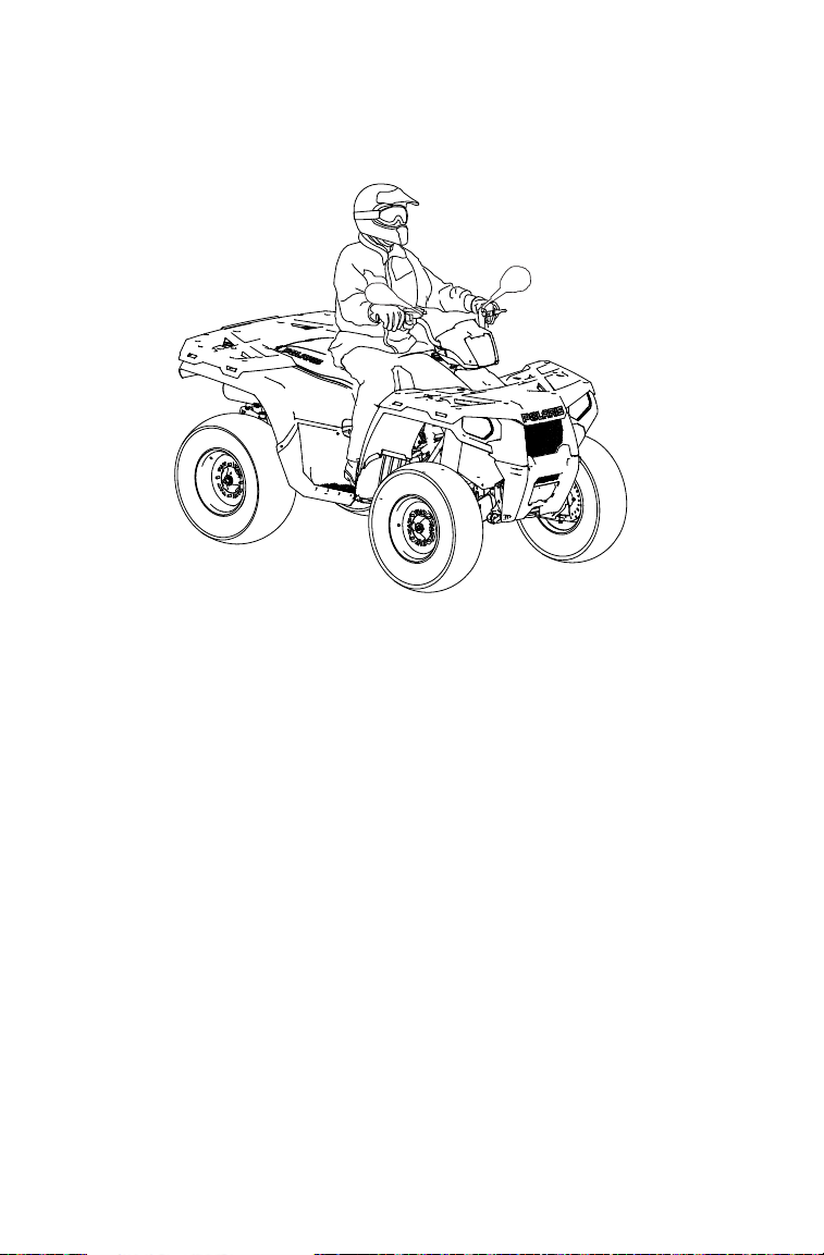
Sportsman Forest 500
Owner's Manual
for Maintenance and Safety
Read this manual carefully. It contains important safety information.
Operation is prohibited for those under 16 years of age.
This is an adult vehicle only.
Page 2
Before you operate this vehicle,
read the owner’s manual
For your nearest Polaris dealer,
call 1-800-POLARIS
or visit www.polarisindustries.com
Polaris Sales Inc., 2100 Hwy 55
Medina, MN 55340
Phone 1-888-704-5290
Part No. 9923174 Rev 01
Printed in USA
*9923174 *
Page 3

WELCOME
Thank you for purchasing a POLARIS vehicle, and welcome to our
world-wide family of POLARIS owners. We proudly produce an exciting line of utility and recreational products.
• Snowmobiles
• All-terrain vehicles (ATVs)
• RANGER utility vehicles
• Victory motorcycles
Always follow the instructions and recommendations in this manual.
The manual contains instructions for minor maintenance, but information about major repairs is outlined in the POLARIS Service Manual
and should be performed only by a factory certified Master Service
Dealer (MSD) technician. Please see your dealer for all of your service
needs during (and after) the warranty period.
For more information about POLARIS, visit us online at
www.polarisindustries.com.
1
Page 4

POLARIS, THE WAY OUT and SPOR TSMAN are registered trademarks of POLARIS
Industries Inc.
Copyright 2010 POLARIS Sales Inc. All information contained within this publication
is based on the latest product information at the time of publication. Due to constant
improvements in the design and quality of production components, some minor discrepancies may result between the actual vehicle and the information presented in this publication. Depictions and/or procedures in this publication are intended for reference use
only. No liability can be accepted for omissions or in acc uracies. Any reprinting or reuse
of the depictions and/or procedures contained within, whether whole or in part, is
expressly prohibited.
The original instructions for this vehicle are in English. Other languages are provided as
translations of the original instructions.
Printed in U.S.A.
SPORTSMAN Forest 500 Owner’ s Manual
P/N 9923174
2
Page 5

TABLE OF CONTENTS
Introduction . . . . . . . . . . . . . . . . . . . . . . . . . . . . 4
Safety . . . . . . . . . . . . . . . . . . . . . . . . . . . . . . . . . 7
Features and Controls. . . . . . . . . . . . . . . . . . . 34
Operation . . . . . . . . . . . . . . . . . . . . . . . . . . . . . 51
Winch Guide . . . . . . . . . . . . . . . . . . . . . . . . . . . 56
Emission Control Systems . . . . . . . . . . . . . . . 62
Maintenance . . . . . . . . . . . . . . . . . . . . . . . . . . . 63
Specifications. . . . . . . . . . . . . . . . . . . . . . . . . 120
POLARIS Products. . . . . . . . . . . . . . . . . . . . . 122
Troubleshooting. . . . . . . . . . . . . . . . . . . . . . . 123
Declaration of Conformity. . . . . . . . . . . . . . . 127
Warranty . . . . . . . . . . . . . . . . . . . . . . . . . . . . . 128
Maintenance Log . . . . . . . . . . . . . . . . . . . . . . 131
Index . . . . . . . . . . . . . . . . . . . . . . . . . . . . . . . . 134
3
Page 6

INTRODUCTION
The following signal words and symbols appear throughout this manual
and on your vehicle. Your safety is involved when these words and symbols are used. Become familiar with their meanings before reading the
manual.
The safety alert symbol indicates a potential personal injury hazard.
DANGER
A DANGER indicates an imminently hazardous situation which, if not avoided,
will result in death or serious injury.
WARNING
A WARNING indicates a hazardous situation which, if not avoided, may result in
death or serious injury.
CAUTION
A CAUTION indicates a hazardous situation which, if not avoided, may result in
minor or moderate injury.
NOTICE
A NOTICE indicates a situation that may result in property damage.
The Prohibition Safety Sign indicates an action NOT to take in order
to avoid a hazard.
The Mandatory Action Sign indicates an action that NEEDS to be
taken to avoid a hazard.
4
Page 7

INTRODUCTION
WARNING
Failure to follow the warnings in this manual can result in serious injury or death.
This POLARIS vehicle is not a toy and can be hazardous to operate. A collision
or rollover can occur quickly, even during routine maneuvers, if you fail to take
proper precautions.
Read and understand your owner's manual and all warnings before operating
this POLARIS vehicle.
Safety Training
When you purchased your new POLARIS vehicle, your dealer offered a
hands-on safety training course. You were also provided with printed
materials that explain safe operating procedures. Review this information on a regular basis.
If you purchased a used POLARIS vehicle from a party other than a
POLARIS dealer, please request free safety training from any authorized POLARIS dealer.
Age Restrictions
This vehicle is an ADULT VEHICLE ONLY. Operation is prohibited
for anyone under 16 years of age.
Restrictions
This vehicle is approved for OFF-ROAD TOWING ONLY. Towing a
trailer with this vehicle on public roads is prohibited.
Equipment Modifications
The warranty on your POLARIS vehicle may be terminated if any
equipment has been added, or if any modifications have been made, that
increase speed or power. The addition of certain accessories, including
(but not limited to) mowers, blades, tires, sprayers and large racks may
change vehicle handling. Use only POLARIS-approved accessories.
Know their function and effect on the vehicle.
5
Page 8
INTRODUCTION
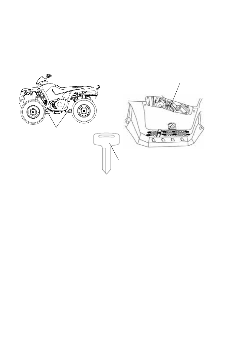
VIN
(front or rear frame)
####
Engine Serial Number
Key Number
Vehicle Identification Numbers
Record your vehicle's identification numbers and key number in the
spaces provided. Remove the spare key and store it in a safe place. An
ignition key can be duplicated only by ordering a POLARIS key blank
(using your key number) and mating it with one of your existing keys.
The ignition switch must be replaced if all keys are lost.
Vehicle Model Number: ___________________________________________________
Frame VIN: ____________________________________________________________
Engine Serial Number: ___________________________________________________
Key Number: ___________________________________________________________
6
Page 9
SAFETY
WARNING
Operator Safety
Serious injury or death can result if you do not follow the instructions and
procedures listed here and throughout this manual.
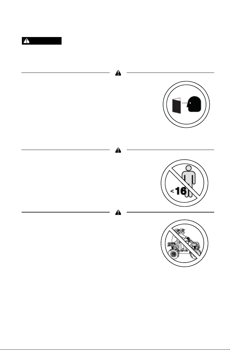
Read and understand all warnings, cautions and
operating procedures in this manual and on the
safety labels before operating the vehicle.
Never operate this vehicle without proper instruction.
Take a training course. Beginners should receive
training from a certified instructor. Contact an
authorized POLARIS dealer or visit the POLARIS
web site at www.polarisindustries.com.
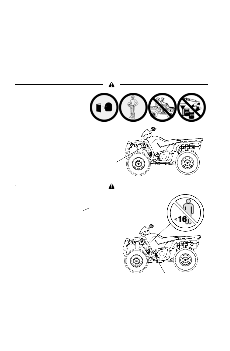
Never permit others to operate the vehicle unless
they have read and understand this manual and all
product labels, and have completed a certified safety training course.
Never allow anyone under 16 years of age to
operate this vehicle.
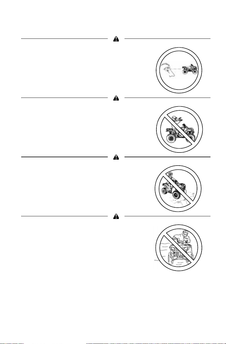
Never carry a passenger. The purpose of the long
seat is to allow the operator to shift position.
7
Page 10
SAFETY
Operator Safety
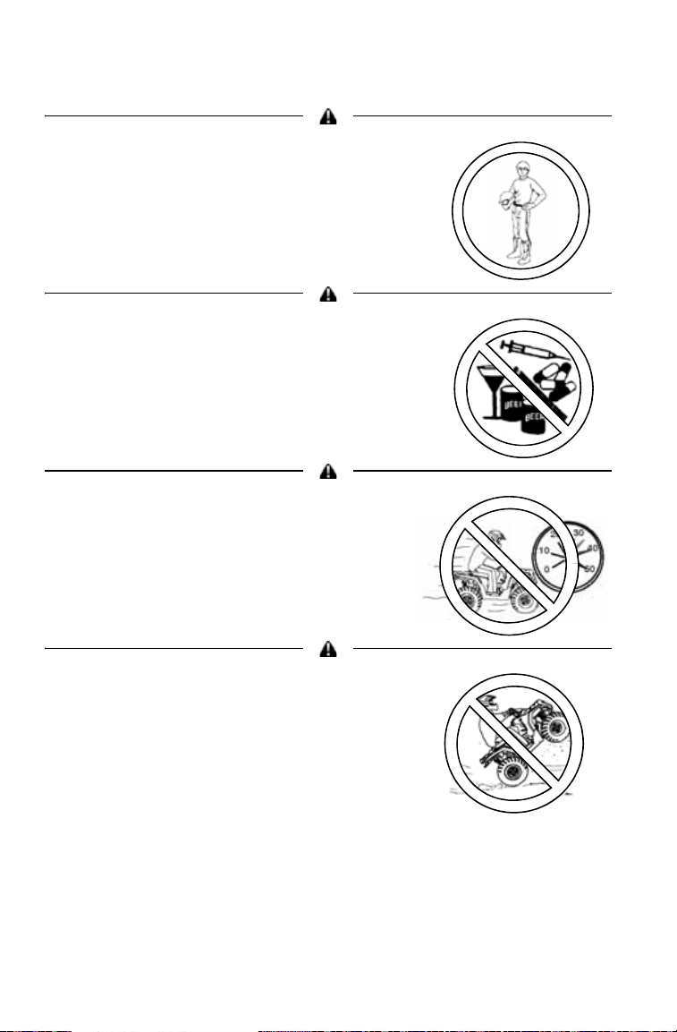
Always wear an approved helmet that fits
properly. Wear eye protection (goggles or
face shield), gloves, boots, long sleeves and
long pants.
Never consume alcohol or drugs before or
while operating this vehicle.
Never operate at excessive speeds. Travel
and turn at speeds appropriate for the terrain,
visibility, operating conditions and your
experience.
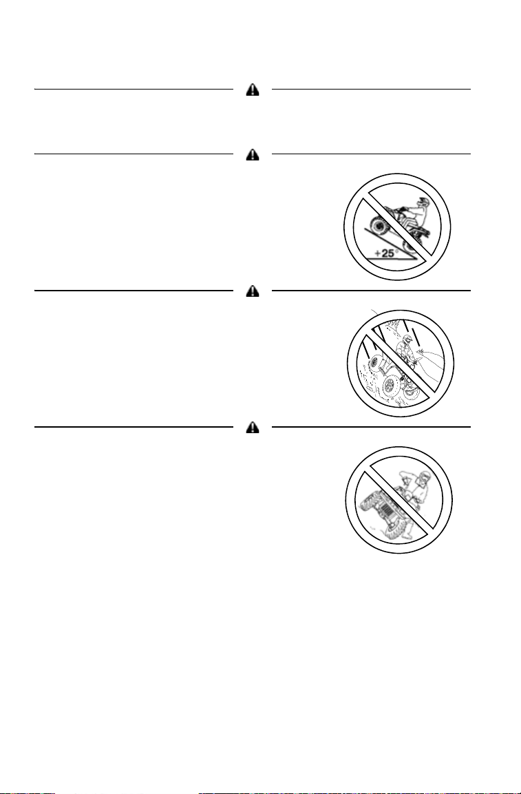
Never attempt jumps or other stunts.
8
Page 11
Operator Safety
Always inspect your POLARIS vehicle before
each use to verify that it's in safe operating
condition. Follow the inspection and
maintenance procedures outlined in this
manual. See page 53.
Keep both hands on the handlebars. Keep
your feet on the footrests.
Always travel slowly when operating on
unfamiliar terrain. Use extra caution.
SAFETY
Always follow the procedures outlined in this
manual for turning. See page 19.
Never turn sharply at excessive speeds,
which can lead to vehicle overturn.
9
Page 12
SAFETY
Operator Safety
If the vehicle has been involved in an accident, always have an authorized
POLARIS dealer inspect the entire vehicle for possible damage, including (but
not limited to) brake, throttle and steering systems.
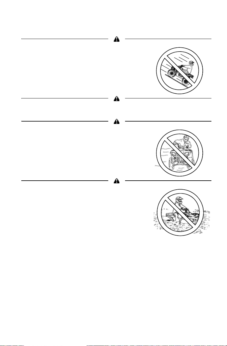
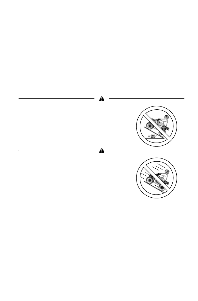
Never operate on hills too steep for the
vehicle or for your abilities. Practice on
smaller hills before attempting larger hills.
Avoid climbing hills steeper than 25.
Always follow the procedures outlined in this
manual for driving on hills. See page 22.
Always follow the procedures outlined in this
manual for driving downhill and for braking on
hills. See page 25.
Always follow the procedures outlined in this
manual for crossing the side of a hill. See
page 24.
Never attempt to turn the vehicle around on
any hill until you've mastered (on level
ground) the turning technique outlined in this
manual.
10
Page 13
SAFETY
Operator Safety
Always follow the procedures outlined in this
manual for braking if you stall or roll
backwards while climbing a hill. Never back
down a hill. See page 26.
Always follow the procedures outlined in this manual for operating over
obstacles. See page 21.
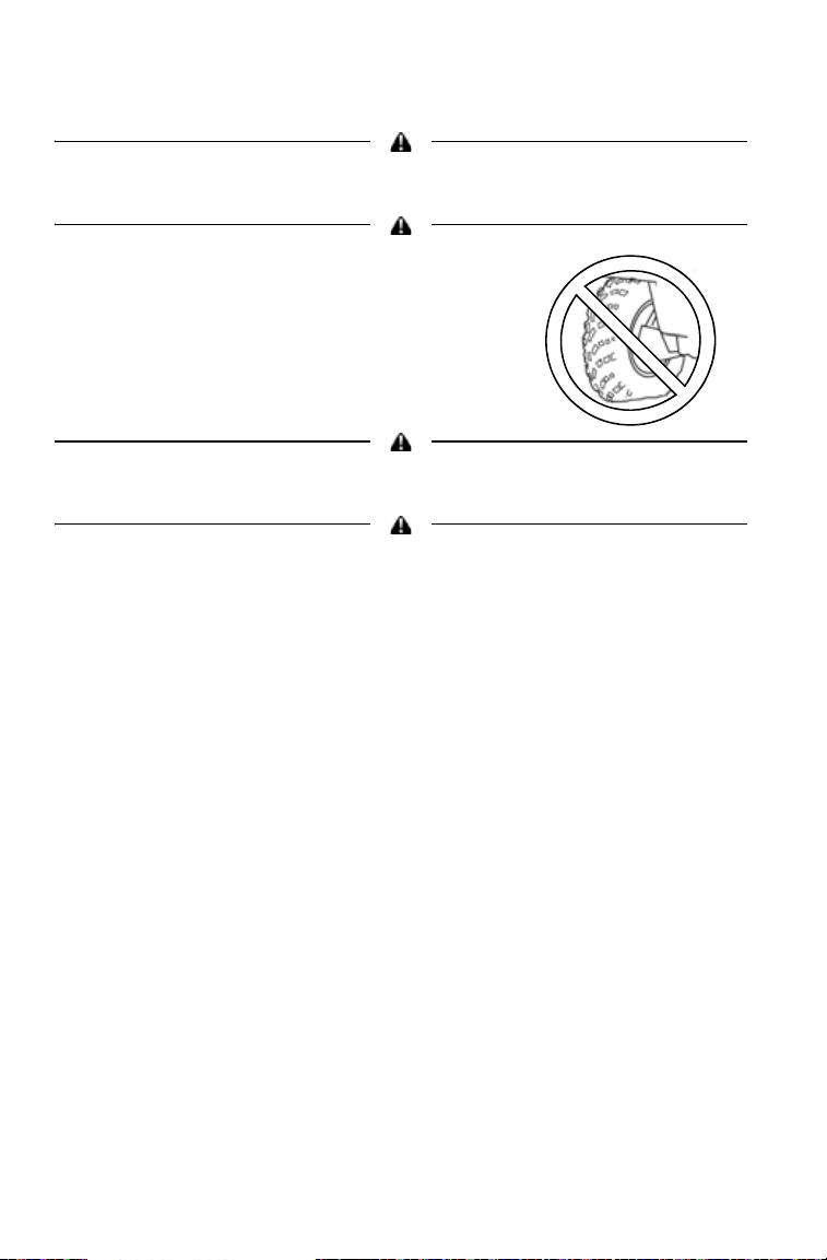
Always follow the procedures outlined in this
manual for operating on slippery or loose
surfaces. Use extra caution. Always avoid
skidding or sliding. See page 20.
Always follow the procedures outlined in this
manual for driving through water. Never drive
through deep or fast-flowing water. See page
28.
11
Page 14
SAFETY
Operator Safety
Always follow the procedures outlined in this manual for driving in reverse. See
page 31.
Always use the size and type of tires
specified for your vehicle. Maintain the proper
tire pressure.
Never modify this POLARIS vehicle through improper installation or use of
accessories.
Never exceed the stated load capacity for your vehicle. Cargo must be properly
distributed and securely attached. Reduce speed and follow the instructions in
this manual for carrying cargo or towing. Allow a greater distance for braking.
12
Page 15
SAFETY
Operator Safety
Never operate the vehicle on a frozen body of water unless you have
independently verified that the ice is sufficiently thick to support the weight and
moving force of the vehicle, you and your cargo, together with any other
vehicles in your party.
Operating on paved surfaces may affect the handling and control of the vehicle
and could result in loss of control. Avoid sudden turns or swift movement of the
handlebars.
Always remove the ignition key when the
vehicle is not in use to prevent unauthorized
use or accidental starting.
Always unlock the steering before starting the engine. See page 40.
Hot components can cause serious burns and fire. Do not touch hot exhaust
system components. Always keep combustible materials away from the exhaust
system.
For more information about safety, contact an
authorized POLARIS dealer or visit the POLARIS web site at
www.polarisindustries.com.
13
Page 16
SAFETY
General
Alert
Hill
Operation
Alert
Age 16
Alert
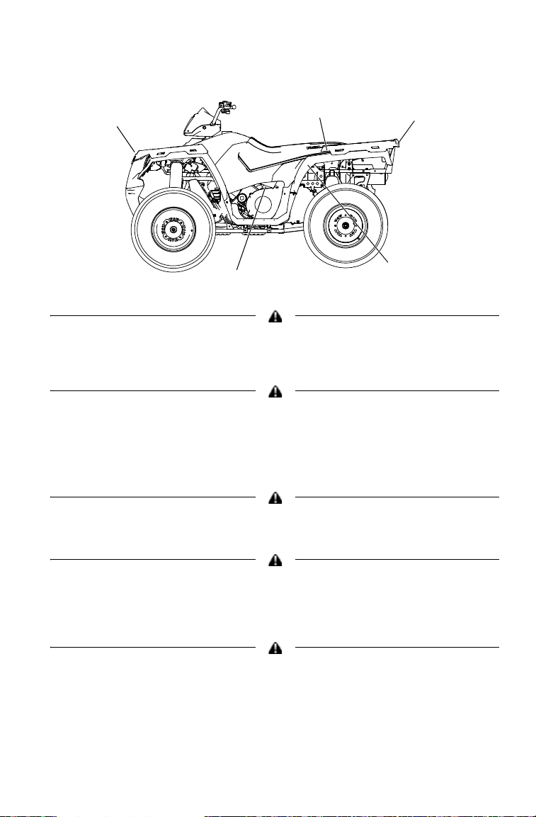
Safety Labels and Locations
Warning labels have been placed on the vehicle for your protection.
Read and follow the instructions on each label carefully. If a label
becomes illegible or comes off, contact your POLARIS dealer to purchase a replacement. Replacement safety labels are provided by
POLARIS at no charge. The part number is printed on the label.
The following pages repeat the information found on each label.
General Alert
(Multi-Lingual)
Before you operate this
vehicle, read the owner’s
manual.
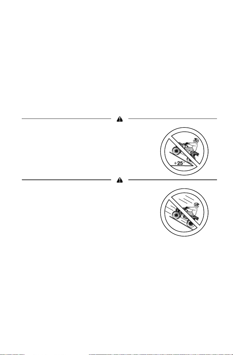
Hill Operation Alert
• Never operate this vehicle on HILLS
steeper than 25 degrees 25.
• To prevent flip-over on hilly terrain,
when going up or down, use throttle
and brakes gradually.
14
Page 17
SAFETY
“No Passenger”
Warning
Rack
Warning
Rack
Warning
Tire Pressure/
Load Alert
Clutch Cover Alert
Safety Labels and Locations
“No Passenger” Warning
WARNING - NEVER ride as a passenger. Passengers can cause a loss of
control, resulting in SEVERE INJURY or DEATH.
Tire Pressure/Load Alert
TIRE PRESSURE IN PSI (KPa): FRONT 5 (34.5) REAR 5 (34.5)
MAXIMUM WEIGHT CAPACITY (Gross Vehicle Weight) INCLUDING
MACHINE, DRIVER AND CARGO IS 1200 LBS. (546 kg). Read Owner's
Manual for more detailed loading information.
Clutch Cover Alert
NO STEP
Rack Warning, Front and Rear
WARNING - DO NOT TOW FROM RACK OR BUMPER. Vehicle damage or
tipover may result causing severe injury or death. Tow only from tow hooks or
hitch. Maximum Rack Loads: Front 90 lbs. (41 kg) Rear 180 lbs. (82 kg)
Reverse Override Alert
Pushing reverse override button may cause sudden increases in power and
traction if too much throttle is applied. Loss of control or forward flipover may
result, especially in AWD. See Owner's Manual.
15
Page 18
SAFETY
Helmet
Eye Protection
Gloves
Boots
Long Pants
Long
Sleeves
E
4
051039
0006.31
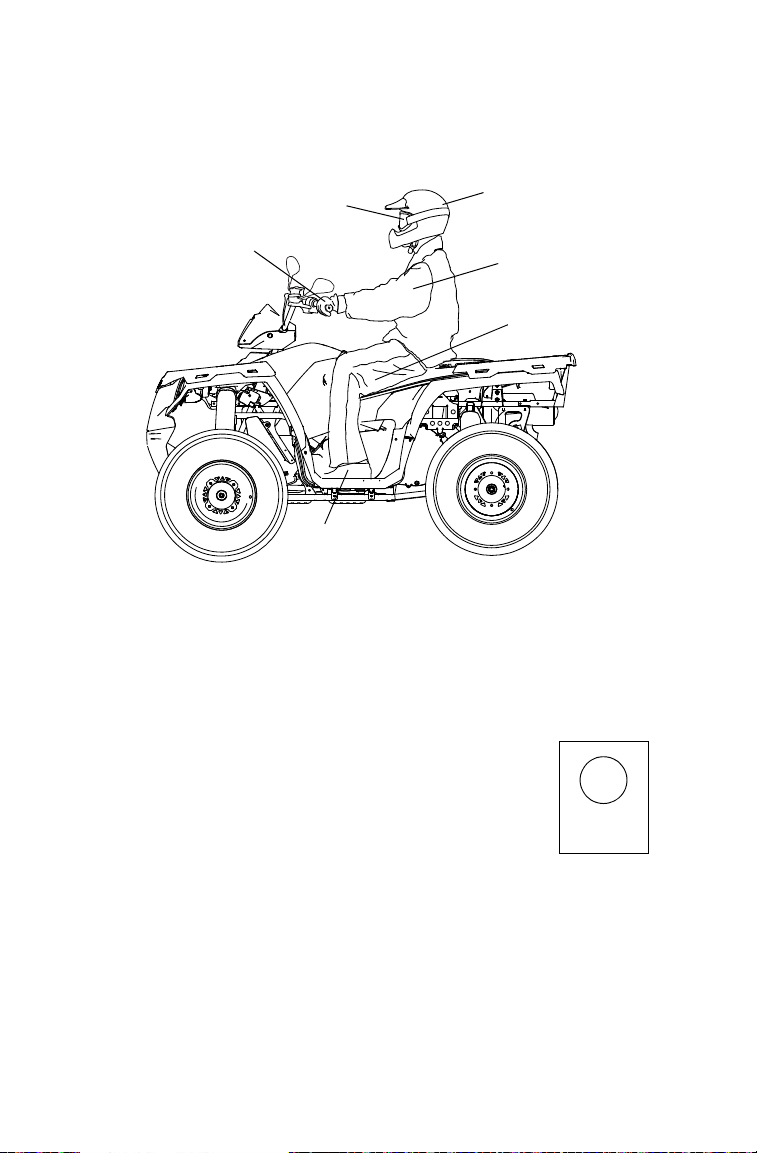
Safe Riding Gear
Always wear protective clothing to reduce the chance of injury.
Helmet
Always wear a helmet that meets or exceeds established safety standards.
Approved helmets in the USA and Canada bear a U.S. Department of
Transportation (DOT) label.
Approved helmets in Europe, Asia and Oceania
bear the ECE 22.05 label. The ECE mark consists
of a circle surrounding the letter E, followed by the
distinguishing number of the country which has
granted approval. The approval number and serial
number will also be displayed on the label.
16
Page 19

SAFETY
Safe Riding Gear
Eye Protection
Do not depend on eyeglasses or sunglasses for eye protection. Whenever riding a POLARIS vehicle, always wear shatterproof goggles or
use a shatterproof helmet face shield. POLARIS recommends wearing
approved Personal Protective Equipment (PPE) bearing markings such
as VESC 8, V-8, Z87.1, or CE. Make sure protective eye wear is kept
clean.
Gloves
Off-road style gloves with knuckle pads are the best for comfort and
protection.
Boots
The best footwear is a pair of sturdy over-the-calf boots with low heels.
Clothing
Always wear long sleeves and long pants to protect arms and legs.
Riding pants with kneepads and a jersey with shoulder pads provide the
best protection.
17
Page 20
SAFETY
Driving Safely
Driving Procedures
1. Sit upright. Keep your feet on the footrests. Keep both hands on the
handlebars.
2. Apply the brakes.
3. Start the engine and allow it to warm up.
4. Shift the transmission into gear.
5. Check your surroundings and determine your path of travel.
6. Release the brakes.
7. Slowly squeeze the throttle lever toward the handlebar to begin
driving.
8. Drive slowly. Practice maneuvering and using the throttle and
brakes on level surfaces.
18
Page 21
SAFETY
Driving Safely
Turning the Vehicle
1. Before turning, activate
a turn signal to alert
others of your intentions. Activate the left
signal before a left
turn. Activate the right
signal before a right
turn.
2. Steer in the direction of
the turn, leaning your
upper body to the
inside of the turn while
supporting your weight
on the outer footrest.
Use the same leaning
technique for turning
in reverse.
3. Practice turning at slow speeds before attempting to turn at faster
speeds.
Always follow the procedures outlined in this
manual for turning. Never turn sharply at
excessive speeds, which can lead to vehicle
overturn.
19
Page 22
SAFETY
Sideways
skid
Turn in direction
of skid
Driving Safely
Driving on Slippery Surfaces
Whenever driving on
slippery or loose surfaces
such as wet trails, gravel,
snow or ice, follow these
precautions:
1. Slow down before
driving onto slippery
surfaces.
2. Engage AWD before
wheels begin to lose
traction.
3. Be alert. Watch the
trail. Avoid quick,
sharp turns.
Tip: To correct a rear wheel
skid, turn the handlebars in the same direction as the skid and shift
body weight forward.
NOTICE: Severe damage
to the drive train
may occur if AWD
is engaged while
the wheels are
spinning. Engage
AWD when the wheels have traction.
Always follow the procedures outlined in this
manual for operating on slippery or loose
surfaces. Use extra caution. Always avoid
skidding or sliding.
20
Page 23
SAFETY
Driving Safely
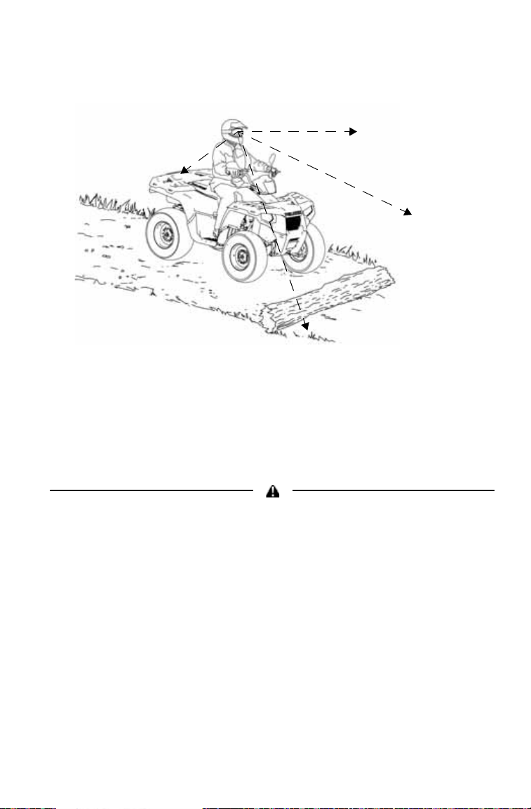
Driving Over Obstacles
1. Always check for obstacles before operating in a new area. Serious
injury or death can result if your vehicle comes in contact with a
hidden obstacle.
2. Be alert. Watch the terrain. Use extra caution.
3. Never operate over large obstacles.
4. Avoid hazards such as logs, rocks and low branches.
Always follow the procedures outlined in this manual for operating over
obstacles.
21
Page 24
SAFETY
25 Maximum
Driving Safely
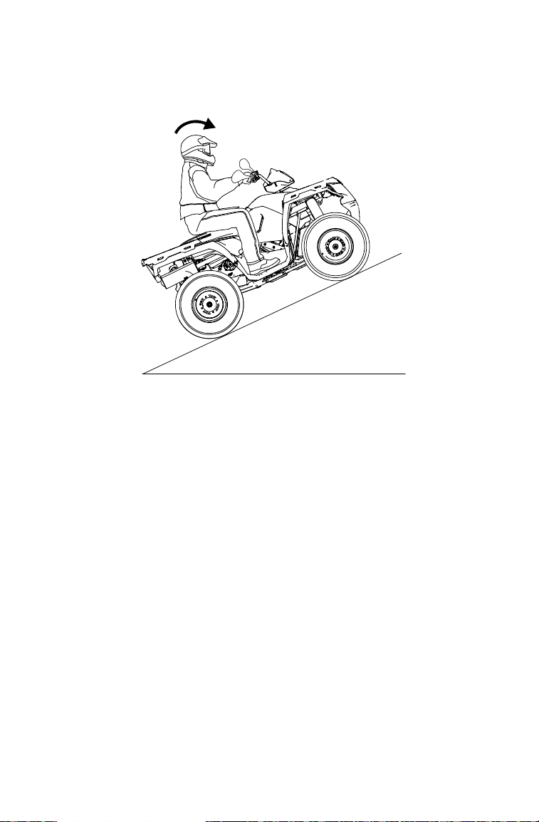
Driving Uphill
Whenever traveling uphill, follow these precautions:
1. Avoid steep hills (25 maximum).
2. Check the terrain carefully.
3. Avoid hills with excessively slippery or loose surfaces.
4. Shift your weight uphill.
5. Drive straight uphill.
6. Keep your feet on the footrests.
7. Drive at a steady rate of speed to avoid stalling.
8. Be alert. Be prepared to take emergency action. This may
include dismounting quickly.
9. Never open the throttle suddenly or make sudden gear changes.
10. Never go over the top of a hill at high speed.
22
Page 25
SAFETY
Driving Safely
Driving Uphill
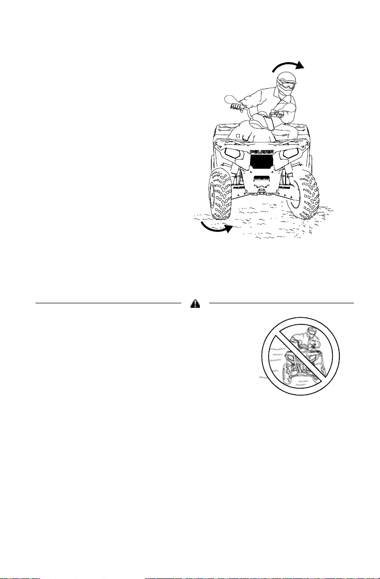
If all forward speed is lost:
Keep your weight uphill.
If the vehicle begins rolling downhill, never apply engine power. Never
apply the brakes aggressively while rolling backwards.
Apply the brakes gradually. When fully stopped, lock the hydraulic
parking brake. See page 39.
Dismount on the uphill side, or to either side if the vehicle is pointed
straight uphill. Turn the vehicle around using the K-Turn. See page 26.
Always follow the procedures outlined in this
manual for climbing hills. Avoid climbing hills
steeper than 25.
Always follow the procedures outlined in this
manual for braking if you stall or roll
backwards while climbing a hill. Never back
down a hill.
23
Page 26
SAFETY
Driving Safely
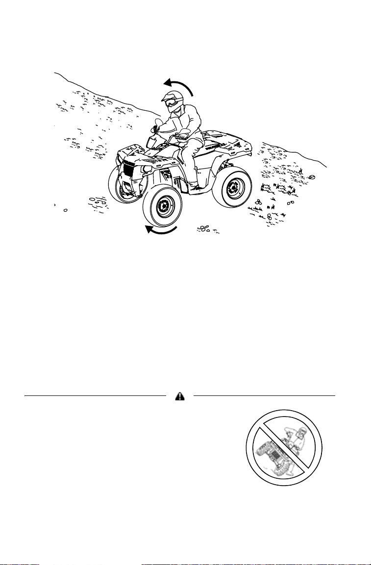
Driving on a Sidehill (Sidehilling)
Avoid crossing the side of a hill (sidehilling) if possible. If sidehilling is
necessary, follow these precautions:
1. Slow down.
2. Avoid hills with excessively slippery or loose surfaces.
3. Shift your weight uphill.
4. Avoid crossing the sides of steep hills.
5. Keep your feet on the footrests.
6. Steer slightly into the hill.
7. If the vehicle begins to tip, quickly turn the front wheels downhill
(if possible) or dismount on the uphill side immediately!
Always follow the procedures outlined in this
manual for crossing the side of a hill.
Never attempt to turn the vehicle around on
any hill until you've mastered (on level
ground) the turning technique outlined in this
manual.
24
Page 27
Driving Safely
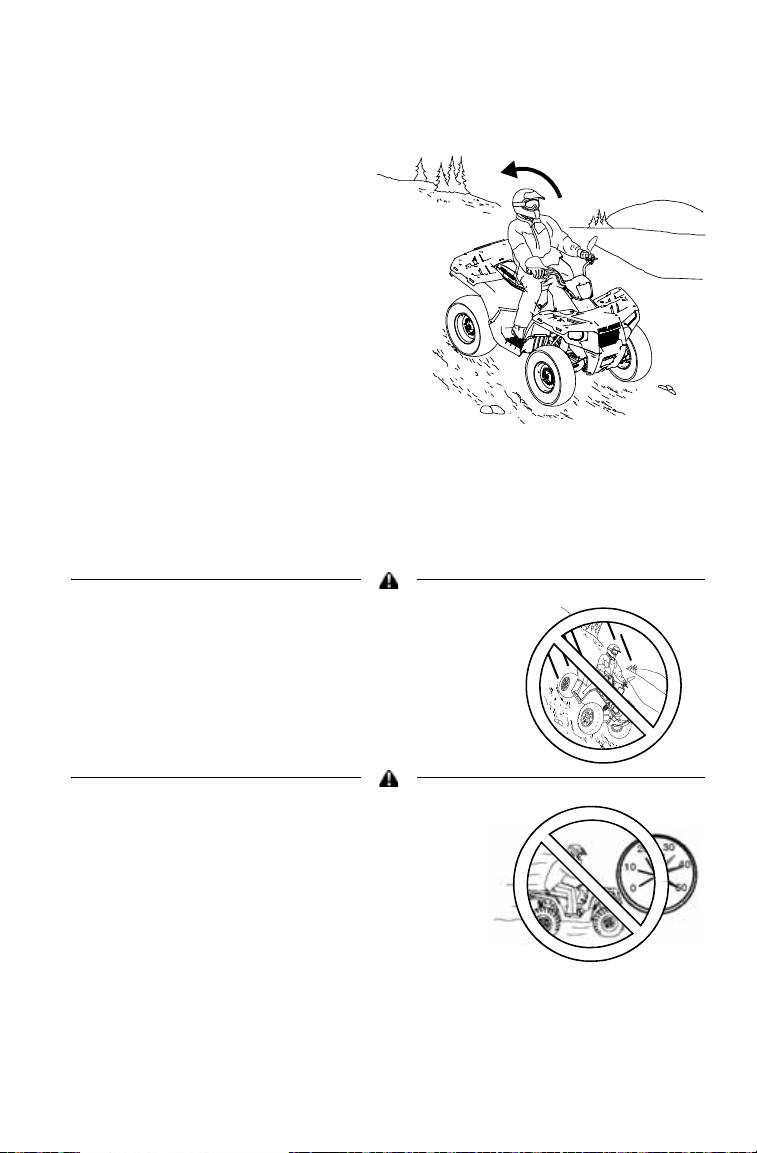
Driving Downhill
When driving downhill, follow
these precautions:
1. Check the terrain carefully.
2. Avoid hills with
excessively slippery or
loose surfaces.
3. Never drive downhill at
high speed.
4. Slow down.
5. Avoid driving downhill at
an angle, which can cause
the vehicle to pitch sharply
to one side. Drive straight
downhill.
6. Shift your weight rearward.
7. Apply the brakes slightly to aid in slowing.
Always follow the procedures outlined in this
manual for driving downhill and for braking on
hills.
SAFETY
Never operate at excessive speeds. Travel
and turn at speeds appropriate for the terrain,
visibility, operating conditions and your
experience.
25
Page 28
SAFETY
2.4 m
Driving Safely
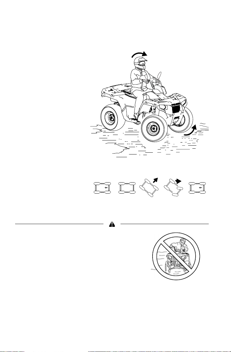
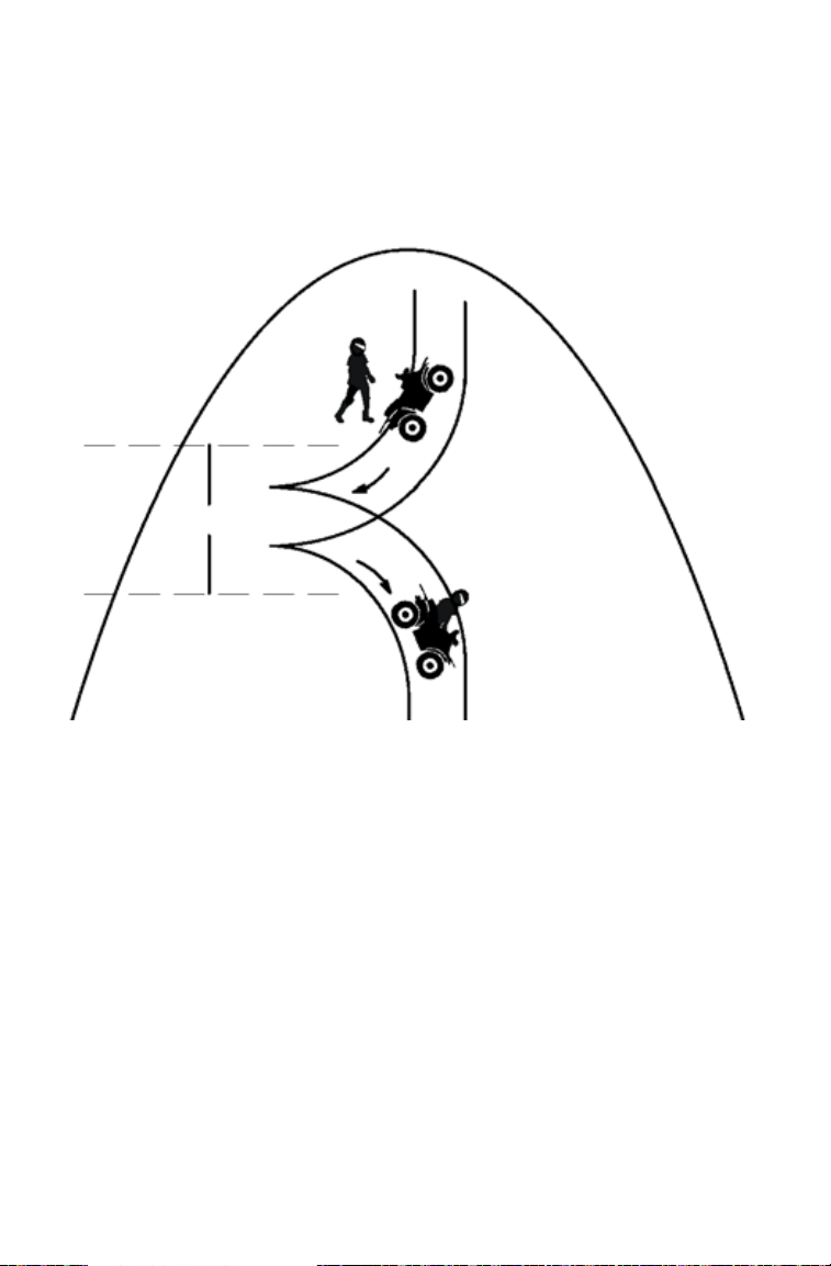
Turning Around on a Hill (K-Turn)
If the vehicle stalls while climbing a hill, never back it down the hill!
Use the K-turn to turn around.
1. Stop the vehicle. Keep your weight uphill.
2. Lock the hydraulic parking brake.
3. Leave the transmission in forward gear. Turn the engine off.
4. Dismount on the uphill side of the vehicle, or on the left if the vehi-
cle is pointing straight uphill.
5. Stay uphill of the vehicle and turn the handlebars full left.
6. Squeeze the brake lever to release the parking brake.
7. Slowly release the brake lever and allow the vehicle to roll around
26
to your right until it's pointing across the hill or slightly downward.
Page 29
SAFETY
Driving Safely
Turning Around on a Hill (K-Turn)
8. Lock the hydraulic parking brake.
9. Remount from the uphill side. Keep your weight uphill.
10. Apply the foot brake.
11. With the transmission still in forward, start the engine.
12. Squeeze and release the brake lever to release the parking brake.
13. Release the foot brake and drive slowly downhill. Control speed
with either the hand or foot brake until the vehicle is on level
ground.
Always follow the procedures outlined in this
manual for climbing hills. See page 22.
Always follow the procedures outlined in this
manual for braking if you stall or roll
backwards while climbing a hill. Never back
down a hill.
27
Page 30
SAFETY
Maximum Depth
Driving Safely
Driving Through Water
Follow these procedures when driving through water:
1. Check water depth and current before crossing.
2. Avoid operating in water deeper than the bottom of the footrests. If
it's unavoidable, travel slowly, balance your weight carefully and
avoid sudden movements. Maintain a slow and steady forward
motion. Do not make sudden turns, stops or throttle changes.
3. Choose a crossing where both banks have gradual inclines.
4. Drive slowly. Avoid rocks and obstacles.
5. Wet brakes may have reduced stopping ability. Always test your
brakes after leaving water. If necessary, apply them lightly several
times to allow friction to dry out the pads.
28
Page 31

SAFETY
Driving Safely
Driving Through Water
If your vehicle becomes fully immersed, and it's impossible to take it to
a dealer before starting it, follow the steps described on page 100. Have
the vehicle serviced by your dealer promptly.
If water has been ingested into the transmission (PVT), follow the procedure on page 105.
Always follow the procedures outlined in this
manual for driving through water. Never drive
through deep or fast-flowing water.
If the vehicle stops while fully submerged, major engine damage can result if the
machine is not thoroughly inspected. Take the vehicle to your dealer before
starting the engine.
29
Page 32

SAFETY
Driving Safely
Parking on an Incline
Avoid parking on an incline. If it's unavoidable, follow these precautions:
1. Stop the engine.
2. Place the transmission in PARK.
3. Always block the rear wheels on the downhill side.
4. Turn the fuel valve off.
30
Page 33

SAFETY
Driving Safely
Driving in Reverse
Follow these precautions when operating in reverse:
1. Avoid backing downhill.
2. Always check for obstacles or people behind the vehicle before
backing.
3. Drive slowly.
4. Apply the foot brake lightly for stopping.
5. Avoid turning at sharp angles.
6. Do not use the override switch unless additional power is required
for vehicle movement. Use with caution.
Tip: Reverse speed is greatly increa sed when the override switch is used. Do
not operate at full throttle. Apply just enough throttle to maintain the desired
speed.
Excessive throttle operation while in the speed limit mode may cause fuel to
build in the exhaust, resulting in engine popping and/or engine damage.
Always follow the procedures outlined in this manual for driving in reverse.
31
Page 34

SAFETY
Driving Safely
Hauling Cargo
Overloading the vehicle or carrying or towing cargo improperly can alter vehicle
handling and may cause loss of control or brake instability. Always follow these
precautions when hauling cargo.
• Read and understand the load distributio n warnings listed on the vehicle
warning labels.
• Never exceed the stated load capacity for this vehicle.
• REDUCE SPEED AND ALLOW GREATER DISTANCES FOR BRAKING
WHEN HAULING CARGO OR TOWING. Use extreme caution when applying
brakes. Avoid situations that require backing downhill.
• When operating over roug h or hilly terrain, reduce speed, cargo and towed
load to maintain stable driving conditions.
• DO NOT BLOCK THE FRONT HEADLIGHT BEAM when carrying loads on
the front rack.
• CARRY LOADS AS LOW ON THE RACK AS POSSIBLE. Carrying a load
high on the rack raises the center of gravity of the vehicle and creates a less
stable operating condition. Reduce load weight when cargo is high. Secure
off-centered loads that cannot be centered and operate with extra caution.
• CARRYING A LOAD on only one rack may cause the vehicle to overturn.
Split the load between the front rack and rear rack, with 1/3 in the front and 2/
3 in the back. Do not exceed load capacities. See specifications beginning on
page 120.
• SECURE ALL LOADS BEFORE OPERATING. Unsecured loads can create
unstable operating conditions, which could result in loss of control of the vehicle.
• OPERATE ONLY WITH STABLE AND SAFELY ARRANGED LOADS. When
handling off-centered loads that cannot be centered, securely fasten the load
and operate with extra caution. Always attach the tow load to the hitch point
designated for your vehicle.
• USE EXTREME CAUTION when operating with loads that extend over the
rack sides. Stability and maneuverability may be adversely affected, causing
the vehicle to overturn.
• TOWING is approved OFF-ROAD ONL Y. Operating this vehicle with a trailer
on public roads is prohibited.
• TOWING SPEED should never exceed 16 km/h. Never exceed 8 km/h when
towing loads in rough terrain, while cornering, or while ascending or descending hills.
32
Page 35

SAFETY
1/3
2/3
Maximum
17 cm
Driving Safely
Hauling Cargo
Towing Loads
Towing is approved OFF-ROAD ONLY. Operating this vehicle with a
trailer on public roads is prohibited. Do not exceed the maximum capacities when towing. Do not tow any trailer on a grade steeper than 15.
Using an improper hitch or exceeding the
maximum tongue weight capacity can
result in serious damage to the vehicle
and will void your warranty. Never install
a hitch longer than 17 cm. Never install
automotive accessories on your
POLARIS vehicle. Always install
POLARIS-approved (or equivalent)
accessories designed for use on the
vehicle.
33
Page 36

FEATURES AND CONTROLS
Mode/Reverse
Override Switch
Main Key
Switch
All Wheel Drive
Switch
Choke
Winch Switch
Momentary High-Beam
Switch
Switches
Mode/Reverse Override Switch
Press the switch to toggle through the speedometer display modes
(except in reverse). See page 45.
To gain additional power while operating in reverse, press the override
switch before opening the throttle. This will cancel the reverse speed
limit function.
The override switch also allows activation of All Wheel Drive in
reverse, if the AWD switch is on.
Activating the override switch with the throttle open and while operating in
reverse can cause loss of control. Do not activate the override switch while the
throttle is open.
Momentary High Beam Switch
Press this switch with your left forefinger to activate the headlight high
beam. The lights will return to low beam when the switch is released.
All Wheel Drive Switch
See page 44 for all wheel drive information.
Winch Switch
See page 56 for winch information.
34
Page 37

FEATURES AND CONTROLS
Override
Switch
Engine
Stop
Switch
Headlight
Switch
Horn
Switch
Hazard
Switch
Turn
Signal
Switch
Switches
Main Key Switch
End all electrical power to the vehicle.
LIGHTS ON position turns the headlights on.
Start the engine. The headlights are not on in this position.
After starting the engine, release the key switch to the POSITION
LIGHTS ON position.
See page 54 for starting procedures.
Engine Stop Switch
The engine will not start or run when the
switch is in the OFF position.
OFF
RUN
Headlight Switch
The lights do not operate unless the main
key switch is on and the engine stop switch
is in the RUN position.
High Beam
Low Beam
35
Page 38

FEATURES AND CONTROLS
Horn
Switch
Hazard
Switch
Turn
Signal
Switch
Switches
Turn Signal Switch
Push the toggle switch either left or
right to activate the corresponding turn signal light. The indicator on the pod will also
flash. Return the toggle to the center position to end the signal.
Horn Switch
Press the horn switch to sound the
horn.
Hazard Warning Switch
Push the hazard warning switch to
cause all turn signal lights to flash simultaneously. Use this feature to alert others of
an emergency or other situation requiring
caution.
36
Page 39

FEATURES AND CONTROLS
Electronic Throttle Control
Mirrors
Use the mirrors to assist in traffic maneuvers. Always check and adjust
the mirrors before driving the vehicle.
Throttle Lever
Failure to check or maintain proper operation of the throttle system can result in
an accident if the throttle lever sticks during operation. Check the lever for
proper operation before starting the engine. Check occasionally during
operation.
Do not start or operate a vehicle with sticking or improperly operating throttle
controls. Contact your dealer for repair if throttle problems arise.
Press the throttle lever to
increase engine speed and
vehicle movement.
Release the lever to reduce
engine speed and vehicle
movement.
Electronic Throttle Control (ETC)
ETC causes the engine to stop if the throttle cable sticks in an open position when the operator releases the throttle lever.
The Electronic Throttle Control (ETC) stops the engine in the event of a throttle
system malfunction. Do not modify the ETC system or replace it with other
throttle mechanisms.
37
Page 40

FEATURES AND CONTROLS
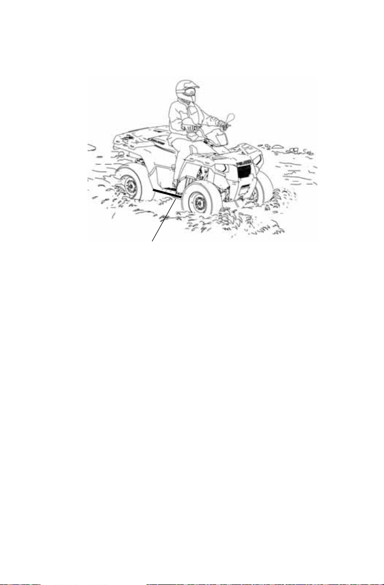
Foot Brake
Foot Brake
The all-wheel foot brake is
located on the right footrest.
The foot brake operates both
front and rear brakes. Press the
brake pedal down with your
foot to apply the all-wheel
brakes.
If the rear wheels begin to skid
or slide while using the foot
brake, reduce brake pressure.
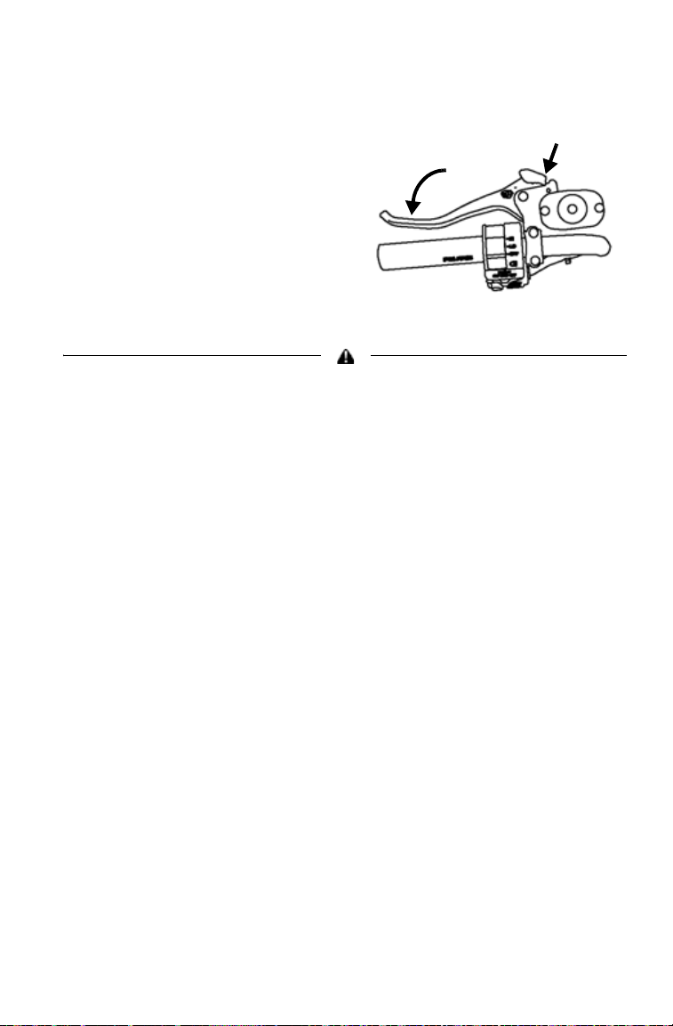
Hand Brake Lever
The hand brake operates both front
and rear brakes. Squeeze the brake
lever toward the handlebar to apply
the all-wheel brakes.
If the rear wheels begin to skid or
slide while using the brake, reduce
lever pressure.
Aggressively applying the brakes when backing down a hill may cause rear
tipover. Aggressively applying the brakes while moving forward may cause the
rear wheels to skid and result in loss of control.
Read this owner's manual and understand the operation of all brake systems on
this vehicle. Always use caution whenever applying the brakes.
38
Page 41
FEATURES AND CONTROLS
Parking Brake
Locking the Parking Brake
1. Place the transmission in
PARK.
2. Squeeze the brake lever
toward the handlebar.
3. Push the parking brake lock
forward to engage the lock.
4. Release the brake lever.
5. To rele ase the parking brake
lock, squeeze and release the brake lever.
Operating the vehicle while the parking brake is engaged could result in an
accident and serious injury or death. Always release the parking brake lock
before operating.
39
Page 42

FEATURES AND CONTROLS
Steering Lock
Lock the steering to prevent unauthorized use or theft of the vehicle.
Tip: Place the steering lock keys in a
safe place. The lock must be
replaced if the keys are lost.
1. Turn the handlebars to the full
left position.
2. Insert the steering lock key
and turn it clockwise.
3. Remove the key.
4. Reverse the procedure to
unlock the steering.
The handlebars are locked in the full left position when the steering is locked.
Always unlock the steering before starting the engine.
40
Page 43

Fuel Valve
OFF
ON
Fuel
Valve
Fuel
Tank
Cap
The fuel valve is located under
the front storage box cover.
OFF: For vehicle storage and
when transporting.
ON: For normal operation.
Choke
The choke assists in starting a
cold engine. Refer to the engine
starting procedure on page 54 for
correct choke and throttle settings
during starting.
Fuel Filter
The in-line fuel filter should be
replaced by your dealer after
every 100 hours of operation or
annually. Do not attempt to clean
the fuel filter.
Fuel Tank Cap
This vehicle is equipped with a digital fuel gauge that will indicate a
low fuel condition. Refuel when the
gauge indicates a low fuel condition.
Always refuel with the engine
stopped, and outdoors or in a well
ventilated area. Refuel on a level
surface.
Remove the fuel tank cap to add fuel
to the fuel tank. Use either leaded or
unleaded gasoline with a minimum
pump octane number of 87=(R+ M/
2) octane. Do not use fuel with etha-
nol content greater than 10 percent,
such as E-85 fuel.
FEATURES AND CONTROLS
41
Page 44
FEATURES AND CONTROLS
Gear
Selector
Transmission Gear Selector
The transmission gear selector is
located on the right side of the
vehicle.
H: High Gear
L: Low Gear
N: Neutral
R: Reverse
P: Park
To shift gears, brake to a complete stop. When the engine is
idling, move the lever to the
desired gear .
Shifting gears with the engine speed above idle or while the vehicle is moving
can cause transmission damage.
Whenever the vehicle is left unattended, always place the transmission
in PARK. The transmission is locked when it’s in PARK.
Belt Life
To extend belt life, use low forward gear when pulling a heavy load at
less than 11 km/h for extended periods and when operating uphill at a
slow speed.
42
Page 45

FEATURES AND CONTROLS
Recoil Starter
Handle
Recoil Starter (if equipped)
If the battery is too weak to start the
engine, use the recoil starter. Follow
the starting procedures on page 54,
cranking the engine with the recoil
starter instead of the main key
switch.
1. Grasp the recoil starter rope
handle tightly.
2. Pull slightly until the starter
mechanism engages.
3. Pull the rope abruptly to start the engine.
Extending the recoil starter rope until it stops can cause damage to the recoil
assembly. Do not extend the starter rope so far that it stops.
If the starter rope handle is not seated properly, water may enter the recoil
housing and damage components. Make sure the handle is fully seated on the
recoil housing, especially when traveling in wet areas.
43
Page 46

FEATURES AND CONTROLS
All Wheel Drive (AWD) System
The AWD switch may be turned on or off while the vehicle is moving.
AWD will not engage until engine speed is below 3100 RPM. AWD
remains engaged until the switch is turned off. There is no limit to the
length of time the vehicle may remain in AWD.
If the switch is turned off while the demand drive unit is engaged, it will
not disengage until the rear wheels regain traction. Engage A WD before
getting into situations where maximum traction is needed. If the rear
wheels are spinning, release the throttle before switching to AWD.
Tip: The override switch al lows activation of AWD in reverse if the AWD switch
is on. See page 34.
Switching to AWD while the rear wheels are spinning may cause severe drive
shaft and gearcase damage. Always switch to AWD while the rear wheels have
traction or are at rest.
AWD
When the AWD switch is on,
the vehicle is in four-wheel
drive and the differential is
locked, providing maximum
traction. The demand drive
unit automatically engages
when the rear wheels lose traction. When the rear wheels
regain traction, the demand drive unit automatically disengages.
2X4
When the 2X4 switch is on,
the vehicle is in two-wheel
drive at all times and the differential is locked.
44
Page 47
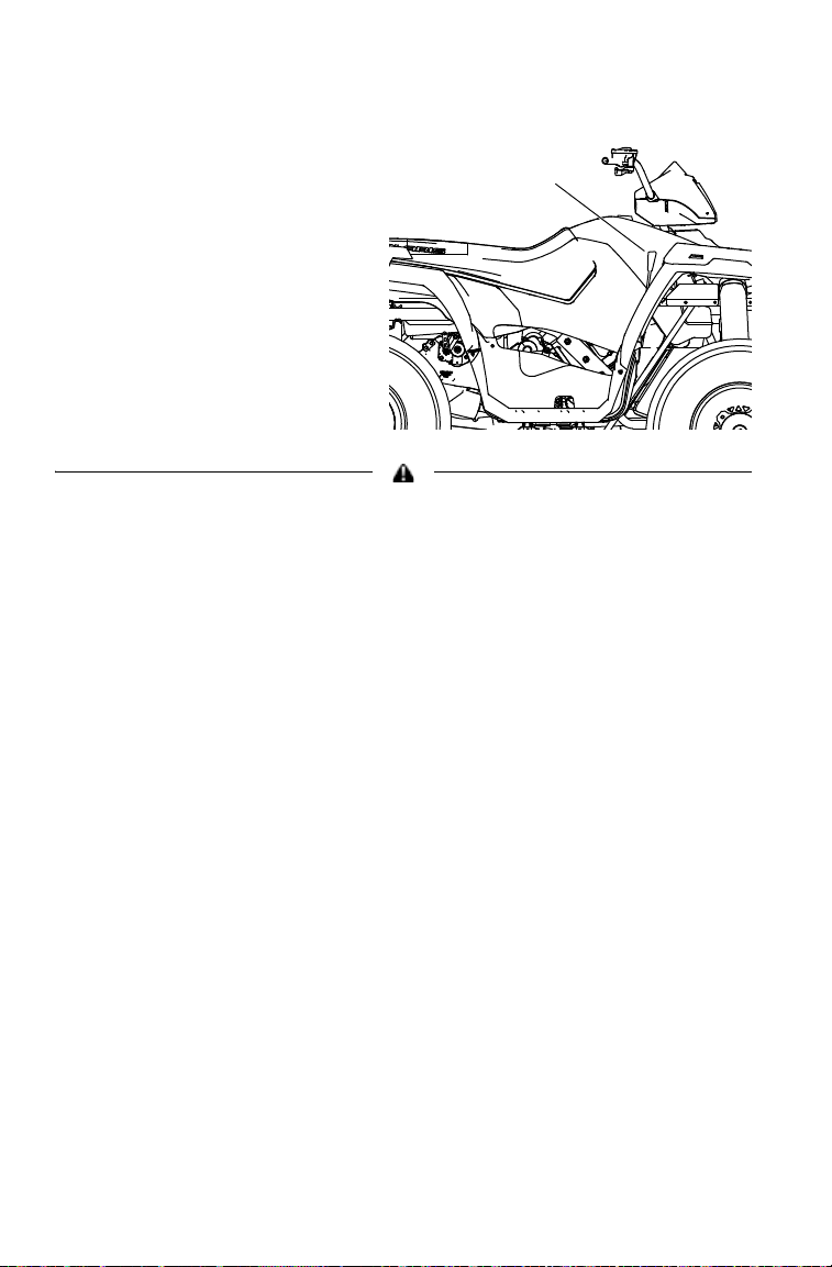
FEATURES AND CONTROLS
Rider
Information
Center
Speedometer
Needle
Speedometer
Instrument Cluster
Your vehicle is equipped with an instrument cluster that senses vehicle
speed from the right front wheel. In addition to showing vehicle speed,
the speedometer needle flashes when a warning condition exists.
The instrument cluster measures distance in miles as well as hours of
operation. It also includes a reverse speed limiter function that limits the
vehicle's speed to approximately 11-14 km/h. Refer to page 34 for additional information.
High water pressure may damage vehicle components. Wash the vehicle by
hand or with a garden hose using mild soap.
Certain products, including insect repellents and chemicals, will damage the
speedometer lens and other plastic surfaces. Do not use alcohol to clean the
instrument cluster. Do not allow insect sprays to contact the lens. Immediately
clean off any gasoline that splashes on the instrument cluster.
45
Page 48

FEATURES AND CONTROLS
1
2
34
5
6
8
7
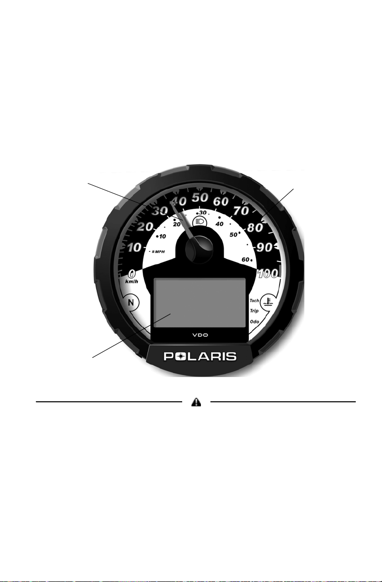
Instrument Cluster
Rider Information Center
The rider information center is located in the instrument cluster . All segments will light up for 2.5 seconds at start-up. If the instrument cluster
fails to illuminate, a battery over-voltage may have occurred and the
instrument cluster may have shut off to protect the electronic speedometer. If this occurs, take the vehicle to your POLARIS dealer for proper
diagnosis.
1. Gear Indicator - This
indicator displays gear
shifter position:
H = High Gear
L = Low Gear
N = Neutral
R = Reverse Gear
P = Park
2. AWD Indicator - This
indicator illuminates
when the AWD switch
is in the AWD position.
3. Engine Hour Display Indicator
4. Service Interval/Diagnostic Mode Indicator
5. Odometer/Tachometer/Tripmeter/ Hour Meter
6. Fuel Gauge - The segments of the fuel gauge show the level of fuel
in the fuel tank. When the last segment clears, a low fuel warning is
activated. All segments will flash, FUEL will display in the LCD,
and the speedometer needle will blink. Refuel immediately.
7. Check Engine Warning Indicator - The word HOT displays if the
engine overheats. Do not operate the vehicle if this warning
appears. Serious engine damage could result.
8. Mode Indicator
46
Page 49

FEATURES AND CONTROLS
Instrument Cluster
Rider Information Center
Standard Modes
Use the MODE button to toggle through the mode options. The reverse
override button is also the MODE button. See page 34.
NOTE: The transmission cannot be in reverse when using this feature.
Odometer Mode
The odometer records the miles traveled by the vehicle.
Trip Meter Mode
The trip meter records the miles traveled by the vehicle on each trip if
it's reset before each trip. To reset the trip meter, select the trip meter
mode. Press and hold the mode button (override button) until the total
changes to 0.
NOTE: In the Rider Information Center, the trip meter display contains a deci-
Hour Meter Mode
This mode logs the total hours the engine has been in operation.
Tachometer Mode
The engine RPM is displayed digitally.
NOTE: Small fluctuations in the RPM from day to day may be normal because
mal point, but the odometer displays without a decimal point.
of changes in humidity, temperature and elevation.
47
Page 50

FEATURES AND CONTROLS
Instrument Cluster
Rider Information Center
Diagnostic Mode
The wrench icon will display when the gauge is in the diagnostic mode.
To exit the diagnostic mode, turn the key switch off and on. Any movement of the tires will also cause the gauge to exit the diagnostic mode.
To enter the diagnostics mode:
1. Turn the key switch off and wait 10 seconds.
2. Lock the parking brake.
3. Place the transmission in neutral.
4. Hold the mode/reverse override button and turn the key switch on.
Release the switch as soon as the display is activated.
5. Use the mode button to toggle through the diagnostic screens.
48
Page 51

FEATURES AND CONTROLS
Instrument Cluster
Rider Information Center
Diagnostic Mode
Battery Voltage Screen
View this screen to check battery voltage level.
Tachometer Screen
View the tachometer to check engine speed.
AWD Diagnostic Screen
The gauge indicates whether or not current is flowing through the AWD
coil (only on models with switchable AWD). This screen is for informational purposes only. Please see your dealer for all major repairs.
Gear Circuit Diagnostic Screen
This screen displays the resistance value (in ohms) being read at the
gear switch input of the gauge. This screen is for informational purposes
only. Please see your dealer for all major repairs.
Programmable service interval
When the hours of engine operation equal the programmed service
interval setting, the wrench icon will flash for 5 seconds each time the
engine is started. When this feature is enabled, it provides a convenient
reminder to perform routine maintenance. See page 50.
The service interval is programmed at 50 hours at the factory.
49
Page 52

FEATURES AND CONTROLS
Instrument Cluster
Rider Information Center
Diagnostic Mode
Programmable service interval
To enable or disable the service interval:
1. Enter the diagnostic mode.
2. Toggle to the service interval screen.
3. Press and hold the mode button for about 7 seconds, until either ON
or OFF appears in the Rider Information Center, depending on your
preference.
To reset the service interval:
1. Enter the diagnostic mode.
2. Toggle to the service interval screen.
3. Press and hold the mode button for 2-3 seconds, until the wrench
icon flashes. Release the button.
4. Press and release the mode button once to advance the setting by
one hour. Press and hold the mode button to advance the hours
quickly.
5. If you scroll past the intended number, press and hold the button
until the hours cycle back to zero.
6. When the desired setting is displayed, wait until the wrench icon
stops flashing. The new service interval is now programmed.
Miles/Kilometers toggle
The display in the tripmeter and odometer can be changed to display
either standard or metric units of measurement.
1. Enter the diagnostic mode.
2. Toggle to the screen that displays either kilometers (KM) or miles
(MP).
3. Press and hold the mode button until the letters flash, then press and
release the button once. When the display stops flashing, the mode
has been set.
50
Page 53

OPERATION
WARNING
Fuel Safety
Gasoline is highly flammable and explosive under certain conditions.
• Use extreme caution whenever handling gasoline.
• Refuel with the engine stopped. Refuel outdoors or in a well-ventilated area.
• Never fill a fuel container while it's on the vehicle. Static electricity between
the rack and container could cause a spark.
• Do not smoke or allow open flames or sparks in or near the area where refu-
eling is performed or where gasoline is stored.
• Do not overfill the tank. Do not fill the tank neck.
• If gasoline spills on your skin or clothing, immediately wash it off with soap
and water and change clothing.
• Turn the fuel valve off whenever the vehicle is stored or parked.
51
Page 54

OPERATION
Break-In Period
The break-in period for your new POLARIS vehicle is the first ten hours
of operation, or the time it takes to use the first two full tanks of gasoline. No single action on your part will increase the life and performance
of your vehicle more than following the procedures for a proper breakin. Careful treatment of a new engine and drive components will result
in more efficient performance and longer life for these components.
Do not operate at full throttle or high speeds for extended periods during
the first three hours of use.
Engine and Drivetrain Break-in
1. Fill the fuel tank with the recommended fuel. See page 41.
2. Check the oil level. Add oil if necessary.
3. Select an open area that allows room to familiarize yourself with
vehicle operation and handling.
4. Drive slowly . Vary the throttle positions. Do not operate at sustained
idle.
5. Perform regular checks on fluid levels, controls and areas outlined
on the daily pre-ride inspection checklist. See page 53.
6. Pull only light loads.
7. Change the oil and filter at 20 hours or one month.
PVT Break-in (Clutches/Belt)
Break in the clutches and belt by operating at slower speeds during the
break-in period as recommended. Pull only light loads. Avoid aggressive acceleration and high speed operation during the break-in period.
52
Page 55

OPERATION
Pre-Ride Checklist
Item Remarks Page
Foot brake Ensure proper operation 38
Hand brake/lever travel Ensure proper operation 85
Brake fluid Ensure proper level 82
Front suspension Inspect, lubricate if necessary 68
Rear suspension Inspect, lubricate if necessary 68
Steering/steering lock Unlock the steering; ensure free oper-
Tires Inspect condition and pressure 90
Wheels/fasteners Inspect, ensure fastener tightness 90
Frame nuts, bolts, fasteners Inspect, ensure tightness Fuel and oil Ensure proper levels 41
Throttle Ensure proper operation 37
Indicator lights/switches Ensure proper operation 34
Engine stop switch Ensure proper operation 35
Mirrors Adjust for best side/rear vision 37
Air filter, pre-filter Inspect, clean 92
Air box sediment tube Drain deposits whenever visible Headlamp Check operation, apply POLARIS
Brake light/tail lamp Check operation, apply POLARIS
Riding gear Wear approved helmet, goggles, and
Winch Inspect cable and switch. 57-58
ation
dielectric grease when lamp is
replaced
dielectric grease when lamp is
replaced
protective clothing
40
70
89
95
96
16
53
Page 56

OPERATION
Tension
Adjusting Nut
Starting the Engine
Engine exhaust contains poisonous carbon monoxide and can cause loss of
consciousness resulting in severe injury or death. Never run an engine in an
enclosed area.
1. Position the vehicle on a level
surface.
2. Place the transmission in PARK.
3. Turn the fuel valve on.
4. Sit on the vehicle.
Tip: The starter interlock will prevent the engine from starting if the transmission
is in gear and the brake is not engaged.
Tip: Do not use the choke if starting a warm engine. Excessive use of the choke
can cause the spark plug to become wet fouled.
5. If the engine is cold, pull the choke
knob out until it stops. If the knob
doesn't stay where positioned,
increase the tension by rotating the
tension adjusting nut clockwise.
Tip: The va riable choke is fully on when the
knob is pulled completely out. The choke
is off when the knob is pushed completely
in. The choke can be adjusted gradually,
depending on how much choke is needed
for starting. Be sure the choke is off during
operation, as excess fuel washing into the
engine oil will increase wear on engine components.
6. Move the engine stop switch to RUN.
54
Page 57

OPERATION
Starting the Engine
7. Do not press the throttle while starting the
engine. Turn the ignition key past the
POSITION LIGHTS ON position to
engage the starter . Activate the starter for
a maximum of five seconds, releasing the
key when the engine starts.
8. If the engine does not start, release the
starter and wait five seconds.
9. Repeat steps 7 and 8 until the engine starts.
Operating the vehicle immediately after starting could cause engine damage.
Allow the engine to warm up for several minutes before operating.
10. If a warm engine has cooled to a point where it does not readily
start, intermittent use of the choke (pulled half way out) may be
necessary. If the engine is over-choked when warm, depress the
throttle lever fully while cranking to aid in starting. Release the
throttle lever immediately after the engine starts. If the engine does
not start and all conditions are favorable, change the spark plug and
try again.
11. If the engine slows or stops, position the choke knob half way in to
allow proper engine warm up. Vary the engine RPM slightly with
the throttle to aid in warm-up. When the engine idles smoothly,
push the choke completely in.
Cold Weather Operation
Internal engine condensation increases as outside temperatures
decrease. If the vehicle is used year-round, check the oil level frequently. A rising oil level could indicate the accumulation of contaminates such as water or excess fuel in the bottom of the crankcase. Water
in the bottom of the crankcase can lead to engine damage and must be
drained. W ater accumulation increases as outside temperature decreases.
See your POLARIS dealer for engine heater kits, which provide quicker
warm-ups and easier starting in colder weather.
55
Page 58

WINCH GUIDE
WARNING
DANGER
Danger Zone
The responsibility for safe operation of the winch ultimately rests with
you, the operator. Read and understand all safety precautions and operating instructions before operating the winch. Careless operation can
result in serious injury. DO NOT use the winch to lift or move people.
Winch Safety Precautions
1. Be alert. Do not operate the winch under the influence of drugs,
alcohol or medication.
2. Practice using the winch so you are prepared to use it in an emer-
gency situation.
Never connect DC powered winches to AC current. Motor damage or fatal
shock may occur.
Stand clear of the cable and load during winching. Keep helpers and spectators
at a safe distance. If a cable pulls loose or breaks under the load, it can lash
back with dangerous force.
3. Beware of the danger zone.
The danger zone is the area
of the rotating wire cable
drum, the fairlead (if fitted),
the cable, the hook and the
motor. Before placing hands
in or near the danger zone,
first relieve tension on load,
then disconnect the control
switch.
4. If you are within four feet of the winch, do not hold the cable and
the remote (if equipped) at the same time.
56
Page 59

WINCH GUIDE
A
B
C
Winch Cable Care
1. The life of a cable is directly related to the care it receives. The wire
cable on a new winch (and any replacement cables) must be respooled under a minimum of a 100-lb. (45.4-kg) load before use.
Failure to do this will result in cable damage.
2. Inspect all cable before use. Mashed, pinched, frayed or kinked
areas severely reduce the load-carrying capability. Replace damaged cable promptly.
3. Prevent kinks before they occur.
A. This is a start of a kink. Straighten
the cable before using it.
B. The cable was pulled and the loop
has tightened to a kink. The cable
is now permanently damaged and
should not be used.
C. The result of kinking is that each
strand pulls a different amount of
load, causing the strands under the
greatest tension to break. This
reduces the load capacity of the
entire cable.
4. Before re-spooling, remove all load from the cable. Hold the han-
dlebar switch lead in one hand and the cable in the other. Move
away from the vehicle as far as the switch will allow. Activate the
switch, walk in several feet of cable, then release the switch. Repeat
this process until the re-spooling is complete.
CAUTION! To avoid injury, always release the switch before your hand comes
within four feet of the fairlead (the physical opening through which the cable
passes).
5. Be sure the cable is distributed evenly and tightly on the drum. A
loosely wound drum may allow the cable to work its way down into
the layers of cable on the drum and become wedged.
6. Do not grease or oil the cable. Doing so causes dirt contamination
that will reduce the life of the cable.
57
Page 60

WINCH GUIDE
DANGER
WARNING
DANGER
Winch Preparation and Inspection
Wear heavy leather gloves whenever
handling cable. Do not allow the cable
to slip through your hands, even with
gloves on. When handling the hook,
always use a handsaver. Never place
fingers into the hook. Placing fingers in
the hook could result in injury.
Inspect the switch and wiring for cracks, pinched spots, frayed wire or loose
connections. A damaged, shortened lead could cause the winch to operate as
soon as it is plugged in.
Never touch the cable or hook while they are in tension
or under load. Even at rest, the winch may have the
cable in tension. Never guide a cable under tension onto
the drum with your hand.
1. Winch with at least five wraps of cable around
the winch drum. With fewer wraps, the cable
could pull loose from the drum under load.
58
Page 61

WINCH GUIDE
WARNING
WARNING
Winch Rigging
Take your time when rigging and use extra caution. Improper rigging can result
in injury in addition to damage to the vehicle and equipment. Never handle the
cable or rigging while another person is at the control switch.
1. Use a nylon sling to
attach the cable to
an anchor point.
CAUTION! Do not attach
the hook back onto the
cable. Doing so can cause
the cable to break.
Always use a handsaver. Do not hold the hook
with your hand. This is important not only
when reeling cable in but also when removing
cable from the winch under power.
2. Run the winch intermittently to take
up cable slack. When using a pulley
block, be sure the cable is running
properly in all pulleys before applying a load.
CAUTION! Never engage or disengage the clutch if the winch is under load,
the cable is in tension or the drum is rotating.
59
Page 62

WINCH GUIDE
Winch Operation
NOTICE: This winch is designed for intermittent use. Prolonged use may result
1. Use common sense.
2. Take your time.
3. Think through the situation.
4. Pay attention to what is going on when you are winching.
5. DO NOT overheat the winch motor. During extended winching,
6. Extended winching will discharge your battery. If the low battery
7. DO NOT overload or stall the winch. If the load is greater than the
8. Avoid continuous side pulls.
9. Never tow the vehicle by the winch cable.
10. Never use the winch cable as a tie-down.
11. Use an anchor point that is stronger than what you are pulling.
12. DO NOT hook the cable back onto itself. This will damage the
in damage due to overheating.
stop and feel the winch motor. The motor should be cool enough to
touch. If not, allow the motor to cool before continuing.
warning light comes on, stop winching. Make sure the transmission
is in neutral or park, then rev the motor for a few minutes until the
warning light goes out. Recharge the battery as soon as possible.
winch is capable of pulling, use a snatch block.
cable.
60
Page 63

WINCH GUIDE
Winch Operation
13. Use as much cable as possible when pulling. Additional wraps of
cable on the spool will significantly reduce the pulling power of
your winch. If the winch is still not capable of pulling the load, use
a snatch block.
14. Never pull with less than five wraps of cable on the spool.
15. Inspect the condition of the cable prior to pulling. If the cable is
frayed or damaged, replace it as soon as possible.
16. DO NOT submerge the winch in water.
61
Page 64

EMISSION CONTROL SYSTEMS
Noise Emission Control System
Do not modify the engine, intake or exhaust components, as doing so
may affect compliance with governmental noise level requirements.
Spark Arrestor
Your POLARIS vehicle has a spark arrestor that was designed for onroad and off-road operation. It is required that this spark arrestor remain
installed and functional when the vehicle is operated.
Exhaust Emission Control System
The emissions from the exhaust of this vehicle are controlled by engine
design, including factory-set fuel delivery and ignition. The engine and
related components must be maintained at POLARIS specifications to
achieve optimal performance.
Engine idle speed is the only adjustment POLARIS recommends that
the operator perform. Any other adjustments should be performed by an
authorized POLARIS dealer.
Electromagnetic Interference
This spark ignition system complies with Canadian ICES-002.
This vehicle complies with the EMC requirements of European direc-
tives 97/24/EC and 2004/108/EC.
Non-ionizing Radiation: This vehicle emits some electromagnetic
energy. People with active or non-active implantable medical devices
(such as heart monitoring or controlling devices) should review the limitations of their device and the applicable electromagnetic standards and
directives that apply to this vehicle.
62
Page 65

MAINTENANCE
Periodic Maintenance Chart
Maintenance intervals in the following chart are based upon average
riding conditions. Vehicles subjected to severe use must be inspected
and serviced more frequently.
The programmable service interval mode on the instrument cluster will
help determine when maintenance service is due. See page 45.
Record maintenance and service in the Maintenance Log beginning on
page 131.
Service and adjustments are important for proper vehicle operation. If
you're not familiar with safe service and adjustment procedures, have a
qualified dealer perform these operations.
Severe Use Definition
• Frequent immersion in mud, water or sand
• Racing or race-style high RPM use
• Prolonged low speed, heavy load operation
• Extended idle
• Short trip cold weather operation
Pay special attention to the oil level. A rise in oil level during cold
weather can indicate contaminants collecting in the oil sump or crankcase. Change oil immediately if the oil level begins to rise. Monitor the
oil level, and if it continues to rise, discontinue use and determine the
cause or see your dealer.
63
Page 66

MAINTENANCE
WARNING
Periodic Maintenance Chart
Improperly performing the procedures marked with a could result in
component failure and cause an accident, which may result in serious injury or
death. Always have an authorized POLARIS dealer perform these services.
Maintenance Chart Key
Perform these operations more often for vehicles subjected to
severe use.
E Emission-related service (Failure to conduct this maintenance will
not void the emissions warranty but may affect emissions.)
Have an authorized POLARIS dealer perform these services.
64
Page 67

MAINTENANCE
Periodic Maintenance Chart
Perform all services at whichever maintenance interval is reached first.
Item Maintenance Interval
Steering - Pre-Ride - Make adjustments as need
Front suspension - Pre- Ride Rear suspension - Pre-Ride Tires - Pre- Ride Brake fluid level - Pre-Ride Brake lever - Pre-Ride Foot brake - Pre-Ride
Brake system - Pre-Ride Wheels/fasteners - Pre-Ride Frame fasteners - Pre- Ride -
Engine oil level - Pre-Ride -
Winch - Pre-Ride - See pages 57-58.
Air filter, pre-filter - Daily - Inspect; clean often; replace
E
Air box sediment
tube
Coolant - Daily - Check level daily, change
Headlight/taillight - Daily - Check operation; apply
Air filter,
E
main element
Recoil housing
(if equipped)
Brake pad wear 10 Monthly 160 Inspect periodically
Battery 20 Monthly 300 Check terminals; clean; test
Demand drive fluid
(front gearcase)
Rear gearcase oil
(if equipped)
Transmission oil 25 Monthly 400 Inspect level; change yearly
Engine breather
E
filter (if equipped)
Perform these procedures more often for vehicles subjected to severe use.
E Emission-Related Service
Have an authorized POLARIS dealer perform these services.
(whichever comes first)
Hours Calendar Kilometers
ed. See Pre-Ride Checklist
on page 53.
as needed
- Daily - Drain deposits when visible
coolant every 2 years
dielectric grease if replacing
- Weekly - Inspect; replace as needed
- Weekly - Drain water as needed,
25 Monthly 400 Inspect level; change yearly
25 Monthly 400 Inspect level; change yearly
25 Monthly 400 Inspect; clean if needed
check often if operating in wet
conditions
Remarks
65
Page 68

MAINTENANCE
Periodic Maintenance Chart
Item Maintenance Interval
Engine oil change
(break-in)
General
lubrication
Shift linkage 50 6 M 800 Inspect, lubricate, adjust
Steering 50 6 M 800 Lubricate
Front suspension 50 6 M 800 Lubricate
Rear suspension 50 6 M 800 Lubricate
Carburetor float
bowl
Throttle Cable/
E
ETC Switch
Choke cable 50 6 M 800 Inspect; adjust; lubricate;
E
E Carburetor air
intake ducts/flange
Drive belt 50 6 M 800 Inspect; adjust; replace as
Cooling system 50 6 M 800 Inspect coolant strength
Engine oil change 100 6 M 1600 Perform a break-in oil change
Oil filter change 100 6 M 1600 Replace with oil change
Oil tank vent hose
(if equipped)
Valve clearance 100 12 M 1600 Inspect; adjust
E
Fuel system 100 12 M 1600 Check for leaks at tank cap,
E
Fuel filter 100 12 M 1600 Replace annually
E
Radiator 100 12 M 1600 Inspect; clean external
Cooling hoses 100 12 M 1600 Inspect for leaks
Engine mounts 100 12 M 1600 Inspect
Exhaust muffler/
pipe
(whichever comes first)
Hours Calendar Kilometers
- 1 M - Perform a break-in oil change
50 3 M 800 Lubricate all fittings, pivots,
50 6 M 800 Drain bowl periodically and
50 6 M 800 Inspect; adjust; lubricate;
50 6 M 800 Inspect duct for proper seal-
100 6 M 1600 Inspect routing, condition
100 12 M 1600 Inspect
at one month
cables, etc.
prior to storage
replace if necessary
replace if necessary
ing/air leaks
needed
seasonally; pressure test
system yearly
at one month
lines, fuel valve, filter, pump,
carburetor; replace lines
every two years
surfaces
Remarks
66
Page 69

Periodic Maintenance Chart
MAINTENANCE
Item Maintenance Interval
Spark plug 100 12 M 1600 Inspect; replace as needed
E
Wiring 100 12 M 1600 Inspect for wear, routing,
Clutches (drive
and driven)
Front wheel
bearings
Brake fluid 200 24 M 3200 Change every two years
Spark arrestor 300 36 M 4800 Clean out
Toe adjustment - Inspect periodically; adjust
Brakes - Inspect daily; adjust as
Headlight aim - Adjust as needed
Perform these procedures more often for vehicles subjected to severe use.
E Emission-Related Service
Have an authorized POLARIS dealer perform these services.
(whichever comes first)
Hours Calendar Kilometers
security; apply dielectric
grease to connectors
subjected to water, mud, etc.
100 12 M 1600 Inspect; clean; replace worn
100 12 M 1600 Inspect; replace as needed
parts
when parts are replaced
needed
Remarks
67
Page 70

MAINTENANCE
Front Prop Shaft Yoke
Lubrication Guide
Always check and change fluids and lubricate greaseable components at the intervals outlined in the Periodic Maintenance Chart
beginning on page 63. Items not listed in the chart should be lubricated at the General Lubrication interval.
Item Lube Method
Engine Oil PS-4 PLUS Performance
Brake Fluid DOT 4 Only See page 82.
Transmission Oil AGL PLUS Transmission
Front Demand Drive
Unit (Front Gearcase)
Front Prop Shaft Yoke POLARIS Premium U-Joint
Synthetic 2W-50
Fluid
Demand Drive Plus Fluid See page 77.
Lube
See page 69.
See page 75.
Grease fittings (3 pumps maximum) every 800 km, before long
periods of storage, or after pressure washing or submerging.
68
Page 71

MAINTENANCE
Engine Oil
Oil Recommendations
Always change the oil filter whenever changing oil.
POLARIS recommends the use of POLARIS PS-4 PLUS Performance
Synthetic 2W-50 4-cycle oil or a similar oil for this engine. Oil may
need to be changed more frequently if POLARIS oil is not used. Always
use 2W-50 oil. Follow the manufacturer's recommendations for ambient
temperature operation. See page 122 for the part numbers of POLARIS
products.
Mixing brands or using a non-recommended oil may cause serious engine
damage. Always use a recommended oil. Never substitute or mix oil brands.
Oil Specifications
Model Lubricant Capacity Drain Plug Torque
SPORTSMAN
Forest 500
PS-4 PLUS Performance
Synthetic 2W-50 4-Cycle
Oil
1.9 liters 19-23 N-m
69
Page 72

MAINTENANCE
Dipstick
Safe
Add Oil
Safe Range
{
Engine Oil
Oil Level
1. Position the vehicle on a level
surface.
2. Place the transmission in PARK.
3. Start the engine. Allow it to idle
for 30 seconds.
4. Stop the engine.
5. Remove the dipstick.
Wipe it dry with a clean
cloth.
6. Reinstall the dipstick
completely.
7. Remove the dipstick and check the oil level. Add oil as needed.
Maintain the oil level in the safe range. Do not overfill.
8. Reinstall the dipstick.
70
Page 73

MAINTENANCE
Drain
Plug
New Sealing Washer
Screen
Fitting
Engine Oil
Oil Change
Hot oil may result in serious burns. Do not allow hot oil to contact skin.
1. Position the vehicle on a level
surface.
2. Place the transmission in PARK.
3. Start the engine. Allow it to idle
for two minutes.
4. Stop the engine.
5. Clean the area
around the drain
plug.
6. Place a drain pan
under the oil tank.
7. Remove the drain
plug.
8. Drain the oil.
9. Clean the drain plug. Reinstall the drain
plug with a new sealing washer.
10. Torque to specification. See page 69.
71
Page 74

MAINTENANCE
Alignment Mark
Engine Oil
Oil Change
11. Disconnect the lower oil deliv-
ery hose and remove the screen
fitting from the oil tank. Clean
the fitting. The fitting threads
must be sealed with LOCTITE
PST 505 or PTFE seal tape.
12. Reinstall the screen fitting and
rotate the fitting clockwise a
minimum of 2 1/2 turns into the
tank threads. Continue to rotate
the fitting until the nipple of the
fitting aligns with the mark on the tank.
Tip: Do not over-tighten. Maximum to rque for the screen fitting is 34 N-m.
13. Reattach the oil line.
14. Place towels under the oil filter.
Using an oil filter wrench, turn the
filter counter-clockwise to remove it.
15. Clean the filter sealing area on the
crankcase.
16. Lubricate the filte r o-ring. Check to make
sure the o-ring is in good condition.
17. Install the new oil filter. After the filter
contacts the crankcase surface, turn it 1/2
turn by hand.
18. Approximately 240 ml of engine oil will remain in the crankcase.
To drain, remove the drain plug on the lower right side of the crankcase.
Tip: The sealing surfaces on the drain plug and crankcase should be clean and
free of burrs, nicks or scratches.
19. Reinstall the drain plug. Torque to specification.
72
Page 75

MAINTENANCE
Safe
Add Oil
Safe Range
{
Engine Oil
Oil Change
20. Remove the dipstick.
21. Add 1.9 liters of recommended oil. If the sump is not drained, add
about 1.6 liters initially.
22. Reinstall the dipstick.
23. Place the transmiss ion in PARK.
24. Prime the oil pump using the procedure
on page 74.
25. Stop the engine. Check for oil leaks.
26. Check the oil level.
Add oil as needed.
Maintain the oil level
in the safe range. Do
not overfill.
27. Reinstall the dipstick.
28. Discard used oil and
filter properly.
73
Page 76

MAINTENANCE
Clamp
Pressure
Relief Slit
Tank
5 cm
Engine Oil
Oil Change
Oil Pump Priming
This priming procedure must be
performed whenever the oil hose
connection between the oil tank and
pump inlet has been disconnected.
1. Clamp the vent line 5 cm from
the oil tank, between the end of
the oil tank vent fitting and the
vent line's pressure relief slit.
2. Start the engine. Allow it to idle
for 10-20 seconds.
3. Remove the vent line clamp. If
the line is bled properly, you should hear a rush of air. If you do not
hear a rush of air, repeat the priming procedure.
74
Page 77

MAINTENANCE
Fill Plug
Fill Level
Transmission Oil
Maintain the oil level at the bottom of the fill plug hole threads. Use the
recommended oil. See page 122 for the part numbers of POLARIS
products.
Oil Recommendations
Lubricant O il Change
Capacity
AGL PLUS Transmission Fluid 948 ml 27-34 N-m 27-34 N-m
Fill Plug
Tor que
Drain Plug
Tor que
Oil Level
1. Position the vehicle on a level
surface.
2. Place the transmission in PARK.
3. Remove the fill plug.
4. Check the oil level. Maintain the
level at the bottom of the fill hole
threads.
5. Add the recommended oil as needed.
Do not overfill.
6. Reinstall the fill plug. Torque to
specification.
75
Page 78

MAINTENANCE
Drain Plug
Transmission Oil
Oil Change
1. Position the vehicle on a level
surface.
2. Place the transmission in PARK.
3. Remove the fill plug.
4. Remove the drain plug.
5. Drain the oil into a drain pan.
6. Clean the drain plug.
7. Reinstall the drain plug. Torque
to specification. See page 75.
8. Add the recommended oil.
9. Reinstall the fill plug. Torque to
specification.
10. Check for leaks.
11. Disca rd used oil properly.
76
Page 79

MAINTENANCE
Drain Plug
Fill Plug
Fill Level
Front Gearcase (Demand Drive) Fluid
Fluid Recommendations
Gearcase Lubricant Capacity Fill Plug
Demand Drive
Unit
Demand Drive Plus Fluid 265 ml 11-14 N-m 15 N-m
Tor que
Use the recommended fluid.
Use of other fluids may
result in improper operation
of components. See page
122 for the part numbers of
POLARIS products.
Maintain the fluid level at
the bottom of the fill hole
threads.
Fluid Level
1. Position the vehicle on a level
surface.
2. Place the transmission in PARK.
3. Remove the fill plug.
4. Add the recommended demand drive fluid as needed.
5. Reinstall the fill plug. Torque to specification.
Drain Plug
Tor que
77
Page 80

MAINTENANCE
Front Gearcase (Demand Drive) Fluid
Fluid Change
1. Position the vehicle on a level
surface.
2. Place the transmission in PARK.
3. Remove the fill plug.
4. Remove the drain plug.
Drain the fluid into a drain
pan.
5. Clean the drain plug.
6. Reinstall the drain plug. Torque
to specification. See page 77.
7. Add the recommended fluid.
8. Reinstall the fill plug. Torque to
specification.
9. Check for leaks.
10. Discard used oil properly.
78
Page 81

MAINTENANCE
Idle Screw
Carburetor
This vehicle is calibrated at the factory for optimal performance at altitudes ranging from zero to 6,000 feet (1800 m) and temperatures of +40
degrees F. (4 degrees C.) or higher. Above 6000 feet (1800 m) the
engine air/fuel mixture becomes overly rich and the engine loses
approximately 3% of its power for each 1000-foot (304.8 m) increase in
elevation. Although this power cannot be regained, adjustments to the
carburetor and drive system can be made to allow more efficient operation. Optional jets, available from your POLARIS dealer, are required
for operation above 6,000 feet and temperatures below +40 degrees F. (4
degrees C.)
Continuous operation of the engine without proper jetting when
required can cause poor performance, overheating or PVT or engine
damage. See your POLARIS dealer for more information about jetting
the ATV for conditions in your area.
Pilot screws are sealed with metal plugs and are serviceable only by
POLARIS dealers.
Carburetor/Engine Idle RPM Adjustment
Recommended engine idle RPM is 1200 +/- 200. If the engine idle
speed is unsatisfactory and all other conditions are favorable, the carburetor can be adjusted.
1. Start the engine and allow it to
warm up for approximately five
minutes.
2. Place the transmission in gear.
3. Lock the parking brake.
4. Turn the screw in (clockwise) to
raise RPM. Turn the screw out
(counter-clockwise) to lower RPM.
79
Page 82

MAINTENANCE
Recovery
Bottle
Cooling System
Any time the cooling system has been drained for maintenance or repair,
replace the coolant with a fresh mixture of antifreeze and water. Drain
the cooling system every two years. Add fresh coolant.
POLARIS recommends the use of POLARIS Premium 60/40 antifreeze/coolant or a 50/50 mixture of high quality aluminum compatible
anti-freeze/coolant and distilled water . POLARIS Premium 60/40 is premixed and ready to use. Do not dilute with water. See page 122 for the
part numbers of POLARIS products.
Always follow the manufacturer's mixing recommendations for the
freeze protection required in your area.
Recovery Bottle Coolant
Some coolant level drop on new
machines is normal, as the system is
purging itself of trapped air. Add
coolant as needed.
Tip: Check the coolant level in the radi-
ator any time the recovery bottle
has run dry.
1. Check the coolant level when
the fluid is cool. Maintain the
coolant level between the minimum and maximum marks on
the bottle (when the fluid is
cool).
2. Remove the left side panel. See
page 88.
3. View the coolant level.
4. Add coolant as needed.
5. Reinstall the side panel.
80
Page 83

MAINTENANCE
Radiator
Cap
Cooling System
Radiator Coolant
Escaping steam can cause severe burns. Never remove the pressure cap while
the engine is warm or hot.
1. Remove the front box/rack.
2. Remove the radiator pressure
cap.
3. If coolant is not visible,
slowly add coolant through
the radiator filler neck.
4. Reinstall the pressure cap.
Tip: Use of a non-standard pressure
cap will not allow the recovery
system to function properly. Contact your dealer for the correct
replacement part.
5. Reinstall the front box/rack.
81
Page 84

MAINTENANCE
Brake Fluid
Check brake fluid levels for both brake systems before each ride.
Always maintain brake fluid at the recommended level. Do not overfill.
The brakes should feel firm when they're applied. Spongy or weak
brakes may indicate a fluid leak or low fluid level. A low fluid level
may also mean that brake pads are worn and need to be replaced. Do not
operate the vehicle with spongy or weak brakes. See your dealer for service.
Operating the vehicle with a spongy brake can result in loss of braking, which
could cause an accident. Never operate the vehicle with spongy-feeling brakes.
If the fluid level is low add DOT 4 brake fluid only . See page 122 for the
part numbers of POLARIS products.
An over-full master cylinder may cause brake drag or brake lock-up, which could
result in serious injury or death. Maintain brake fluid at the recommended level.
Do not overfill.
Under normal operation, the diaphragm extends into the reservoir as
fluid level drops. If the fluid level is low and the diaphragm is not
extended, a leak is likely and the diaphragm should be replaced. To
ensure proper diaphragm operation, always fill the reservoir as needed
whenever the cover is loosened or removed. Do not overfill.
Never store or use a partial bottle of brake fluid. Brake fluid is hygroscopic,
meaning it rapidly absorbs moisture from the air. The moisture causes the
boiling temperature of the brake fluid to drop, which can lead to early brake fade
and the possibility of accident or severe injury. After opening a bottle of brake
fluid, always discard any unused portion.
82
Page 85

Brake Fluid
Master Cylinder
Indicator
Window
Full
Low
Hand Brake
The master cylinder is located on
the left handlebar. Maintain the
fluid level 6 mm below the top
edge of the master cylinder. Do
not overfill.
1. Position the vehicle on a
level surface. Make sure
the handlebars are straight.
2. View the fluid level
through the indicator window (eye) on the top of the
master cylinder.
Tip: The eye will appear dark when
the fluid level is full. When fluid
is low, the eye will be clear.
3. Add the recommended
fluid as needed. Do not overfill.
MAINTENANCE
83
Page 86

MAINTENANCE
Foot Brake Fluid
Reservoir
Brake Fluid
Foot Brake
1. Position the vehicle on a
level surface.
2. Remove the seat.
3. View the fluid level in the
master cylinder.
4. Maintain the fluid level
between the minimum and
maximum marks. Do not
overfill.
84
Page 87
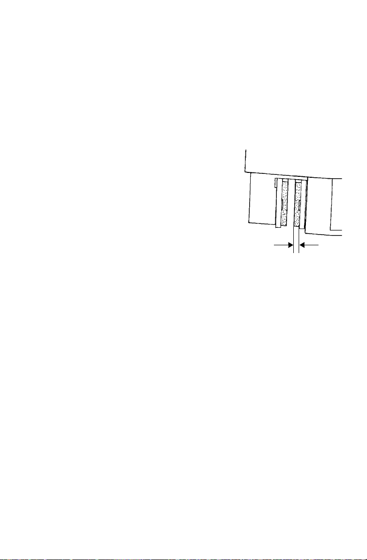
MAINTENANCE
1 mm
Brakes
The front and rear brakes are hydraulic disc brakes, activated by applying the foot brake. The handlebar brake is also hydraulic. Both brake
systems are self-adjusting.
Brake Inspections
Perform the following checks to keep the brake systems in good operating condition. Check more often if brakes are used heavily under normal
operation.
1. Always keep brake fluid at an adequate
level. See page 82.
2. Check the brake systems regularly for
fluid leaks.
3. Check the brakes for excessive travel or
spongy feel.
4. Check the friction pads for wear, damage
and looseness. Replace the pads when
the friction material is worn to 1 mm.
5. Check the security and surface condition
of the disc.
85
Page 88

MAINTENANCE
String
Stand
2
1
FRONT
Toe Alignment
Do not attempt to adjust tie rod alignment. All tie rod adjustments should be
performed by an authorized POLARIS dealer.
Use the following procedure to check the toe alignment of the vehicle.
The recommended toe alignment is 3-6 mm toe out.
1. Position the vehicle on a
level surface.
2. Place the handlebars in a
straight-ahead position.
3. Tie a length of string
between two stands as
shown in the illustration.
Position the stands so
that the string is flush
with the side of the rear
tire. If available, you may
use a long straight-edge
instead of string.
4. Measure the distance
from the string to the rim
at the front (1) and rear
(2) of the front rim. The
rear measurement should
be 2-3 mm more than the front measurement on each side of the
vehicle to obtain the recommended 3-6 mm toe out alignment.
5. Repeat the measurement procedure on the other side of the vehicle.
6. If you discover improper alignment, see your POLARIS dealer for
service.
86
Page 89
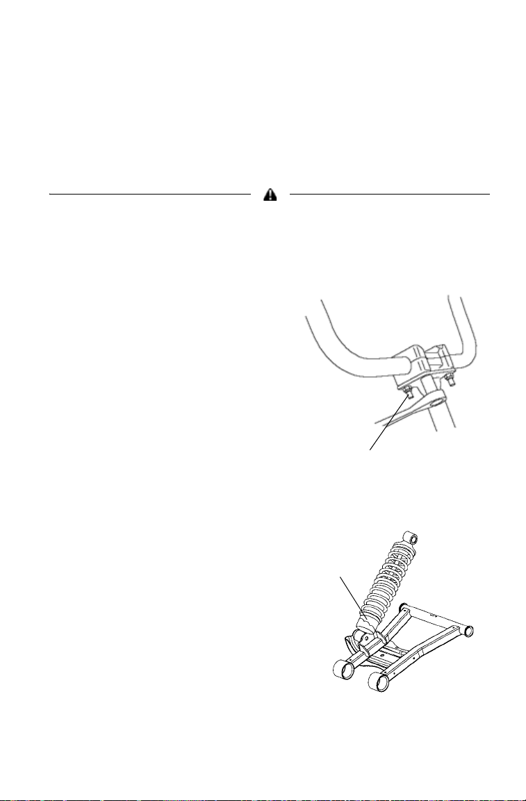
MAINTENANCE
14-17 N-m
Adjuster
Steering Assembly
Check the steering assembly of the vehicle periodically for loose nuts
and bolts. If loose nuts and bolts are found, see your POLARIS dealer
for service before operating the vehicle.
Handlebar Adjustment
The handlebars can be adjusted for rider preference.
Improper adjustment of the handlebars or incorrect torquing of the adjuster
block tightening bolts can cause limited steering or loosening of the handlebars,
resulting in loss of control. Follow the adjustment procedures exactly, or see
your POLARIS dealer for service.
1. Remove the upper headlight
pod.
2. Loosen the four handlebar bolts.
3. Adjust the handlebar to the
desired height.
Tip: Be sure the handlebars do not con-
tact the gas tank or any other p a rt
of the machine when turned fully to
the left or right.
4. Torque the front two bolts to
14-17 N-m, then torque the rear
two bolts. A gap of up to 3 mm
will remain at the rear bolts.
Rear Spring Adjustment
The rear shock absorber spring
is adjusted by rotating the
adjuster either clockwise or
counter-clockwise to increase
or decrease spring tension.
87
Page 90

MAINTENANCE
Screws
Rivets
Side Panel Removal
1. Remove the seat.
2. Grasp the rear of the side panel
near the rear cab.
3. With a firm motion, pull the
panel outward to disengage the
side panel from the grommet.
4. Pull the panel downward and
rearward to remove it.
Footwell Removal
1. Remove the four screws on
the bottom of the footwell.
2. Use a flat screwdriver or
sidecutters to remove the
plastic rivets securing the
footwell to the fenders.
3. Remove the footwell.
88
Page 91

Throttle Cable Freeplay
Boot
Lock Nut
Adjuster
1.6-3.2 mm
Adjust throttle cable freeplay at the handlebar.
1. Locate the throttle cable adjuster
at the handlebar.
2. Squeeze the end of the rub-
ber boot and slide it far
enough to expose the end of
the inline cable adjuster.
3. Loosen the adjuster lock nut.
4. Rotate the boot to turn the
adjuster until 1.6-3.2 mm of
freeplay is achieved at the
thumb lever. Move the throttle lever back and forth while
adjusting.
MAINTENANCE
5. Tighten the lock nut.
6. Squeeze the end of the
rubber boot and slide it
over the cable adjuster to
its original position.
WARNING! Engine RPM should not increase when steering is turned full left or
right. Readjust cable freeplay if this occurs.
89
Page 92

MAINTENANCE
WARNING
3 mm
Tires
Operating your vehicle with worn tires, improperly inflated tires, non-standard
tires or improperly installed tires will affect vehicle handling and could cause an
accident.
• Maintain proper tire pressure as described on the label on your vehicle and in
the specifications section of the owner's manual.
• Use only original equipment size and type whe n replacing tires.
• Make sure the wheels are installed properly.
• Replace tires when the tread depth measures 3 mm or less.
Refer to the specifications section beginning on page 120 for recommended tire type, size and pressure.
Tire Tread Depth
Always replace tires
when tread depth is
worn to 3 mm or less.
Front Wheel Hub Tightening
Front wheel bearing tightness and spindle nut retention are critical component operations. All service must be performed by your authorized
POLARIS dealer.
Wheel Nut Torque Specifications
Check the wheel nut torques occasionally and when they've been loosened for maintenance service.
Nut Type Nut Torque
Lug Nut (Aluminum Wheels) 41 N-m
2-Piece Flange Nut
(Steel Wheels)
90
PLUS 1/4 TURN
37 N-m
Page 93

MAINTENANCE
Tires
Wheel Removal/Installation
Always use original equipment size and type when replacing tires. Install wheels
properly.
1. Position the vehicle on a level
surface.
2. Place the transmission in PARK.
3. Loosen the wheel nuts
slightly.
4. Place a suitable stand under
the footrest frame to raise the
wheel slightly off the ground.
5. Remove the wheel nuts.
6. Remove the wheel.
7. Place the wheel on the hub.
8. Install the wheel nuts finger
tight.
9. Lower the vehicle to the
ground.
10. Torque the wheel nuts to
specification. See torque
chart on page 90.
91
Page 94

MAINTENANCE
Main Filter
Pre-Filter
Air Filter
Always clean and replace the air and breather filters at the intervals outlined in the Periodic Maintenance Chart beginning on page 63.
1. Position the vehicle on a level
surface.
2. Place the transmission in PARK.
3. Remove the seat.
4. Release the air box
cover clips.
5. Remove the air
box cover.
6. Loosen the hose
clamp.
7. Remove the filter.
8. Remove the pre-filter
from the filter.
9. Wash the pre-filter in soapy water. Rinse and air dry.
10. Replace the filter if needed.
11. Reverse the steps to reinstall all components.
92
Page 95

MAINTENANCE
Breather
Filter
Breather Filter/Hose
The breather filter is on the hose between the engine and air box.
1. Remove the left side panel.
See page 88.
2. Remove the hose clamps from
the filter and pull the filter out
of the hoses.
3. Inspect the filter for debris.
Blow gently through the filter
in the direction of the arrow to
check for clogging. Replace a
damaged or clogged filter.
4. Check the hoses for cracks, deterioration, abrasion, or leaks.
Replace as needed.
5. Reinstall the filter and hose clamps.
Tip: The filter is effective with the arrow pointing in either direction.
Operation of your vehicle without a breather filter can cause engine damage.
93
Page 96

MAINTENANCE
7.6 m
5 cm
X
X
Lights
Headlight Beam Adjustment
The headlight beam can be adjusted slightly upward or downward.
1. Position the vehicle on a level
surface. The headlight should be
approximately 7.6 m from a wall.
2. Place the transmission in PARK.
3. Measure the distance from the floor to the center of the headlight
and make a mark on the wall at the same height. Include rider
weight on the seat when measuring.
4. Start the engine.Turn the headlight switch to high beam.
5. Observe the headlight aim on the wall. The most intense part of the
headlight beam should be 5 cm below the mark on the wall.
6. Tighten or loosen the lower headlight screws to adjust the beam
upward or downward or to the left or right.
94
Page 97

MAINTENANCE
Position Light
Collar
Socket
Headlamp
Lights
Poor lighting can result in loss of control or an accident. Lights become dirty
during normal operation. Wash the headlights and taillights frequently.
Hot components can cause serious burns to skin. Do not service the headlamps
until they've cooled.
Headlight/Position Light Lamp Replacement
When servicing a halogen lamp, do
not touch the lamp with bare fingers.
Oil from your skin leaves a residue,
causing a hot spot that will shorten
the life of the lamp. Hold the plastic
part of the lamp.
1. Place the transmission in PARK.
2. Remove the front box/rack.
3. Remove the plug at the back of the
headlight.
4. Pull the harness plug to disconnect
it from the back of the headlight.
5. Position light: Rotate the socket to
remove it. Go to step 6.
Headlamp: Reach under the
bumper and remove the rubber
cover from the back of the
headlight. Turn the collar counterclockwise and carefully remove
the collar and socket.
6. Remove the lamp. Apply dielectric
grease to the socket and install a
new lamp.
7. Reverse all steps to reassemble the
headlight.
95
Page 98

MAINTENANCE
Lights
Taillight Lamp Replacement
1. Place the transmission in
PARK.
2. Rotate the taillight socket
counter-clockwise to remove it.
3. Remove the lamp.
4. Apply dielectric grease to the
socket.
5. Install the new lamp. Test the lamp for proper operation.
6. Reinstall all components in reverse order.
Front Turn Signal Replacement
If a front turn signal light becomes
inoperable, the lamps cannot be
replaced. Replace the entire signal lamp
assembly.
Rear Turn Signal Lamp Replacement
1. Place the transmission in PARK.
2. Rotate the turn signal socket
counter-clockwise to remove it.
3. Remove the lamp.
4. Apply dielectric grease to the
socket.
5. Install the new lamp. Test the lamp for proper operation.
6. Reinstall all components in reverse order.
96
Page 99

Fuse Replacement
Fuse Panel
Fuses
5or61520 20
If the engine stops or will not
start, or if you experience other
electrical failures, a fuse may need
replacement. Locate and correct
any short circuits that may have
caused the blown fuse, then
replace the fuse. Spare fuses are
provided in a compartment.
1. Remove the front box/rack.
2. Remove the suspect fuse from
the fuse panel. If the fuse is
blown, install a new fuse with
the same amperage.
3. Reinstall the front box/rack.
MAINTENANCE
97
Page 100

MAINTENANCE
Spark Plugs
Spark Plug Recommendations
Refer to the specifications section beginning on page 120 for the recommended spark plug type and gap for your vehicle. Torque spark plugs to
specification.
Plug Condition Torque Specification
New Spark Plug 12-15 N-m
Previously Installed Spark Plug 23-27 N-m
Spark Plug Inspection
Spark plug condition is indicative of engine operation. Check the spark
plug firing end condition after the engine has been warmed up and the
vehicle has been driven at higher speeds. Immediately check the spark
plug for correct color . See page 99.
Normal Spark Plug
The normal insulator tip is tan or brown. There will be few combustion
deposits. The electrodes are not burned or eroded. This indicates the
proper type and heat range for the engine and the service.
The tip should not be white. A white insulator tip indicates overheating,
caused by use of an improper spark plug or incorrect carburetor adjustments.
Wet Fouled Spark Plug
The wet fouled insulator tip is black. A damp oil film covers the firing
end. There may be a carbon layer over the entire nose. Generally, the
electrodes are not worn. General causes of fouling are excessive oil, use
of non-recommended oil, improper use of the choke, or incorrect carburetor adjustments.
98
 Loading...