

Page 1

PMS 419
Sportsman 550 EPS
Sportsman XP 850 H.O.
Sportsman XP 850 H.O. EPS
Owner's Manual
for Maintenance and Safety
Read this manual carefully. It contains important safety information.
Operation is prohibited for those under 16 years of age.
This is an adult vehicle only.
Page 2

WARNING
The engine exhaust from this product contains chemicals
known to the State of California to cause cancer, birth defects
or other reproductive harm.
A card containing important ATV safety information should be
attached to the owner's manual on the next page. If you cannot
locate this card, or if it has been removed, please call 1-800342-3764 for assistance.
Page 3

WELCOME
Thank you for purchasing a POLARIS vehicle, and welcome to our
world-wide family of POLARIS enthusiasts. Be sure to visit us online at
www.polaris.com for the latest news, new product introductions,
upcoming events, career opportunities and more.
Here at POLARIS we proudly produce an exciting line of utility and
recreational products.
• Snowmobiles
• All-terrain vehicles (ATVs)
• Low emission vehicles (LEVs)
• RANGER® utility vehicles
• VICTORY® motorcycles
• GEM® vehicles
We believe POLARIS sets a standard of excellence for all utility and
recreational vehicles manufactured in the world today. Many years of
experience have gone into the engineering, design, and development of
your POLARIS vehicle, making it the finest machine we’ve ever
produced.
For safe and enjoyable operation of your vehicle, be sure to follow the
instructions and recommendations in this owner’s manual. Yo ur manual
contains instructions for minor maintenance, but information about
major repairs is outlined in the POLARIS Service Manual and should be
performed only by a factory certified Master Service Dealer® (MSD)
technician.
Your POLARIS dealer knows your vehicle best and is interested in your
total satisfaction. Be sure to return to your dealership for all of your service needs during, and after, the warranty period.
1
Page 4

POLARIS®, SPORTSMAN® and SPORTSMAN XP® are registered trademarks of
POLARIS Industries Inc.
MAXXIS
Copyright 2013 POLARIS Sales Inc. All information contained within this publication
is based on the latest product information at the time of publication. Due to constant
improvements in the design and quality of production components, some minor discrepancies may result between the actual vehicle and the information presented in this publication. Depictions and/or procedures in this publication are intended for reference use
only. No liability can be accepted for omissions or in acc uracies. Any reprinting or reuse
of the depictions and/or procedures contained within, whether whole or in part, is
expressly prohibited.
The original instructions for this vehicle are in English. Other languages are provided as
translations of the original instructions.
Printed in U.S.A.
2014 SPORTSMAN 550 EPS
2014 SPORTSMAN XP 850 H.O. / SPORTSMAN XP 850 H.O. EPS
Owner’s Manual P/N 9924659
® is a registered trademark of Maxxis International.
2
Page 5

TABLE OF CONTENTS
Introduction . . . . . . . . . . . . . . . . . . . . . . . . . . . . 4
Safety . . . . . . . . . . . . . . . . . . . . . . . . . . . . . . . . . 7
Features and Controls. . . . . . . . . . . . . . . . . . . 24
Operation . . . . . . . . . . . . . . . . . . . . . . . . . . . . . 53
Winch Guide . . . . . . . . . . . . . . . . . . . . . . . . . . . 71
Emission Control Systems . . . . . . . . . . . . . . . 83
Maintenance . . . . . . . . . . . . . . . . . . . . . . . . . . . 84
Troubleshooting. . . . . . . . . . . . . . . . . . . . . . . 133
POLARIS Products. . . . . . . . . . . . . . . . . . . . . 137
Specifications. . . . . . . . . . . . . . . . . . . . . . . . . 138
Warranty . . . . . . . . . . . . . . . . . . . . . . . . . . . . . 142
Maintenance Log . . . . . . . . . . . . . . . . . . . . . . 150
Index . . . . . . . . . . . . . . . . . . . . . . . . . . . . . . . . 154
3
Page 6

INTRODUCTION
The following signal words and symbols appear throughout this manual
and on your vehicle. Your safety is involved when these words and symbols are used. Become familiar with their meanings before reading the
manual.
The safety alert symbol indicates a potential personal injury hazard.
DANGER
A DANGER indicates a hazardous situation that, if not avoided, will result in
death or serious injury.
WARNING
A WARNING indicates a hazardous situation that, if not avoided, could result in
death or serious injury.
CAUTION
A CAUTION indicates a hazardous situation that, if not avoided, could result in
minor or moderate injury.
NOTICE
A NOTICE indicates a situation that could result in property damage.
The Prohibition Safety Sign indicates an action NOT to take in order
to avoid a hazard.
The Mandatory Action Sign indicates an action that NEEDS to be
taken to avoid a hazard.
4
Page 7

INTRODUCTION
WARNING
Failure to heed the warnings and safety precautions contained in this manual
can result in severe injury or death. A POLARIS ATV is not a toy and can be
hazardous to operate. This vehicle handles differently than other vehicles, such
as motorcycles and cars. A collision or rollover can occur quickly, even during
routine maneuvers like turning, or driving on hills or over obstacles, if you fail to
take proper precautions.
• Read this owner’s manual. Understand all safety warnings, precautions and
operating procedures before operating a POLARIS A TV. Keep this manual
with the ATV.
• Never operate an ATV without proper instruction. Take a training course.
• This vehicle is an ADULT VEHICLE ONLY . Operation is prohibited for anyone
under 16 years of age.
• Never permit a guest to operate the ATV unless the guest has read this
manual and all product labels and has completed a certified safety training
course.
European Vibration and Noise
The driver-perceived noise and hand/arm and whole body vibration levels of this machinery is measured per prEN 15997.
The operating conditions of the machinery during testing:
The vehicles were in like-new condition. The environment was con-
trolled as indicated by the test procedure(s).
The uncertainty of vibration exposure measurement is dependent on
many factors, including:
• Instrument and calibration uncertainty
• Variations in the machine such as wear of components
• Variation of machine operators such as experience or physique
• Ability of the worker to reproduce typical work during measurements
• Environmental factors such as ambient noise or temperature
5
Page 8
INTRODUCTION
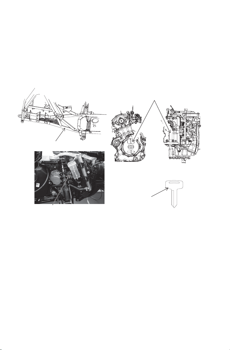
Vehicle Identification Numbers
Record your vehicle's identification numbers and key number in the
spaces provided. Remove the spare key and store it in a safe place. An
ignition key can be duplicated only by ordering a POLARIS key blank
(using your key number) and mating it with one of your existing keys.
The ignition switch must be replaced if all keys are lost.
The manufacturer’s label is located on the front right side of the vehicle
behind the radiator.
Engine Serial Number
VIN
550 850
##
Key
Number
Manufacturer’s Label
Vehicle Model Number: ___________________________________________________
Frame VIN: ____________________________________________________________
Engine Serial Number: ___________________________________________________
Key Number: ___________________________________________________________
6
Page 9

SAFETY
Safety Training
ATV safety training is a top priority for POLARIS. POLARIS strongly
encourages you and any family members who will be riding the ATV to
take a training course.
If you purchased a new POLARIS ATV in the United States, your dealer
provided information about the authorized ATV RiderCourse
available to you and your eligible family members. This training is
included in the purchase price of your ATV. You were also provided
with printed materials that explain safe operating procedures. You
should review this information on a regular basis.
If you purchased a used POLARIS ATV in the United States, you can
sm
enroll in the ATV RiderCourse
for a fee. Call ATV Enrollment Express
at (800) 887-2887 or visit www.atvsafety.org.
If you purchased a POLARIS ATV outside the United States, please
contact your dealer or local law enforcement agencies for information
about safety training.
A POLARIS ATV is an off-road vehicle. Familiarize yourself with all
laws and regulations concerning the operation of this vehicle in your
area.
W e strongly advise you to strictly follow the recommended maintenance
program outlined in your owner's manual. This preventive maintenance
program is designed to ensure that all critical components on your vehicle are thoroughly inspected at specific intervals.
FOR MORE INFORMATION ABOUT ATV SAFETY in the United
States, call the Consumer Product Safety Commission at 1-800638-2772, or visit www.cpsc.gov, visit www.atvsafety.org, or call
POLARIS at 1-800-342-3764.
sm
that is
7
Page 10
SAFETY
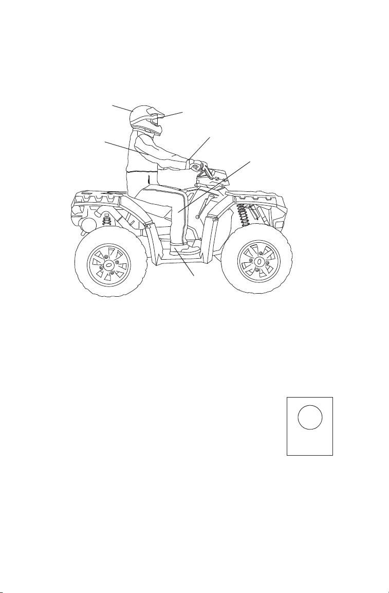
Safe Riding Gear
Always wear appropriate clothing when riding an ATV. Wear protective
clothing for comfort and to reduce the chance of injury.
Helmet
Long
Sleeves
Eye Protection
Gloves
Long Pants
Boots
Helmet
Wearing a helmet can prevent a severe head injury. Whenever riding a
POLARIS vehicle, always wear a helmet that meets or exceeds established safety standards.
Approved helmets in the USA and Canada bear a U.S. Department of
Transportation (DOT) label.
Approved helmets in Europe, Asia and Oceania
bear the ECE 22.05 label. The ECE mark consists
of a circle surrounding the letter E, followed by the
distinguishing number of the country which has
granted approval. The approval number and serial
4
E
051039
0006.31
number will also be displayed on the label.
8
Page 11

SAFETY
Safe Riding Gear
Eye Protection
Do not depend on eyeglasses or sunglasses for eye protection. Whenever riding a POLARIS vehicle, always wear shatterproof goggles or
use a shatterproof helmet face shield. POLARIS recommends wearing
approved Personal Protective Equipment (PPE) bearing markings such
as VESC 8, V-8, Z87.1, or CE. Make sure protective eye wear is kept
clean.
Gloves
Off-road style gloves with knuckle pads are the best for comfort and
protection.
Boots
The best footwear is a pair of sturdy over-the-calf boots with low heels.
Clothing
Always wear long sleeves and long pants to protect arms and legs. Riding pants with kneepads and a jersey with shoulder pads provide the best
protection.
Equipment Modifications
We strongly recommend that consumers do not install on a POLARIS
ATV any equipment that may increase the speed or power of the vehicle,
or make any other modifications to the vehicle for these purposes.
The warranty on your POLARIS ATV is terminated if any equipment
has been added to the vehicle, or if any modifications have been made to
the vehicle, that increase its speed or power.
The addition of certain accessories, including (but not limited to) mowers, blades, tires, sprayers, or large racks, may change the handling characteristics of the vehicle. Use only POLARIS-approved accessories, and
familiarize yourself with their function and effect on the vehicle.
9
Page 12
SAFETY
WARNING
Safety Warnings
Failure to operate the ATV properly can result in a collision, loss of control,
accident or overturn, which may result in serious injury or death. Heed all safety
warnings outlined in this section of the owner’s manual. See the OPERATION
section of the owner’s manual for proper operating procedures.
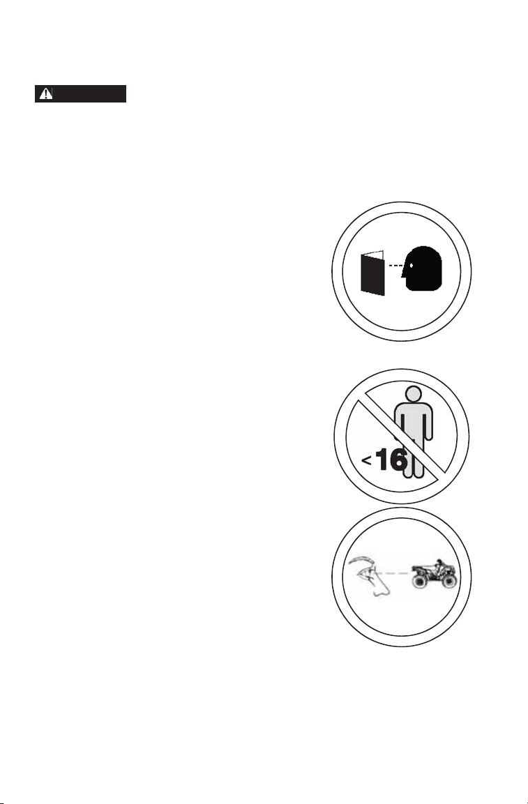
Operating Without Instruction
Operating this ATV without proper instruction
increases the risk of an accident. The operator
must understand how to operate the ATV properly
in different situations and on different types of
terrain.
Beginning and inexperienced operators should
complete the recommended safety training before
operating this vehicle. See page 7.
Never permit a guest to operate the ATV unless the
guest has read this manual and all product labels
and has completed a certified safety training
course.
Age Restrictions
This vehicle is an ADULT VEHICLE ONLY.
Operation is prohibited for anyone under 16 years
of age.
Even though a child may be within the
recommended age group for operating some ATVs,
he/she may not have the skills, abilities, or
judgment needed to operate an ATV safely and
could be susceptible to accident or injury.
Failure to Inspect Before Operating
Failure to inspect and verify that the ATV is in safe
operating condition before operating increases the
risk of an accident.
Always inspect the ATV before each use to make
sure it's in safe operating condition.
Always follow all inspection and maintenance
procedures and schedules described in the
owner's manual.
10
Page 13
SAFETY
Safety Warnings
Handling Gasoline
Gasoline is highly flammable and explosive under certain conditions.
• Always exercise extreme caution whenever handling gasoline.
• Always refuel with the engine stopped, and outdoors or in a well ventilated
area.
• Do not smoke or allow open flames or sparks in or near the area where refueling is performed or where gasoline is stored.
• Do not overfill the tank. Do not fill the tank neck.
• If gasoline spills on your skin or clothing, immediately wash it off with soap
and water and change clothing.
Exposure to Exhaust
Engine exhaust fumes are poisonous and can cause loss of consciousness or
death in a short time. Never start the engine or let it run in an enclosed area.
The engine exhaust from this product contains chemicals known to cause
cancer, birth defects or other reproductive harm. Operate this vehicle only
outdoors or in well-ventilated areas.
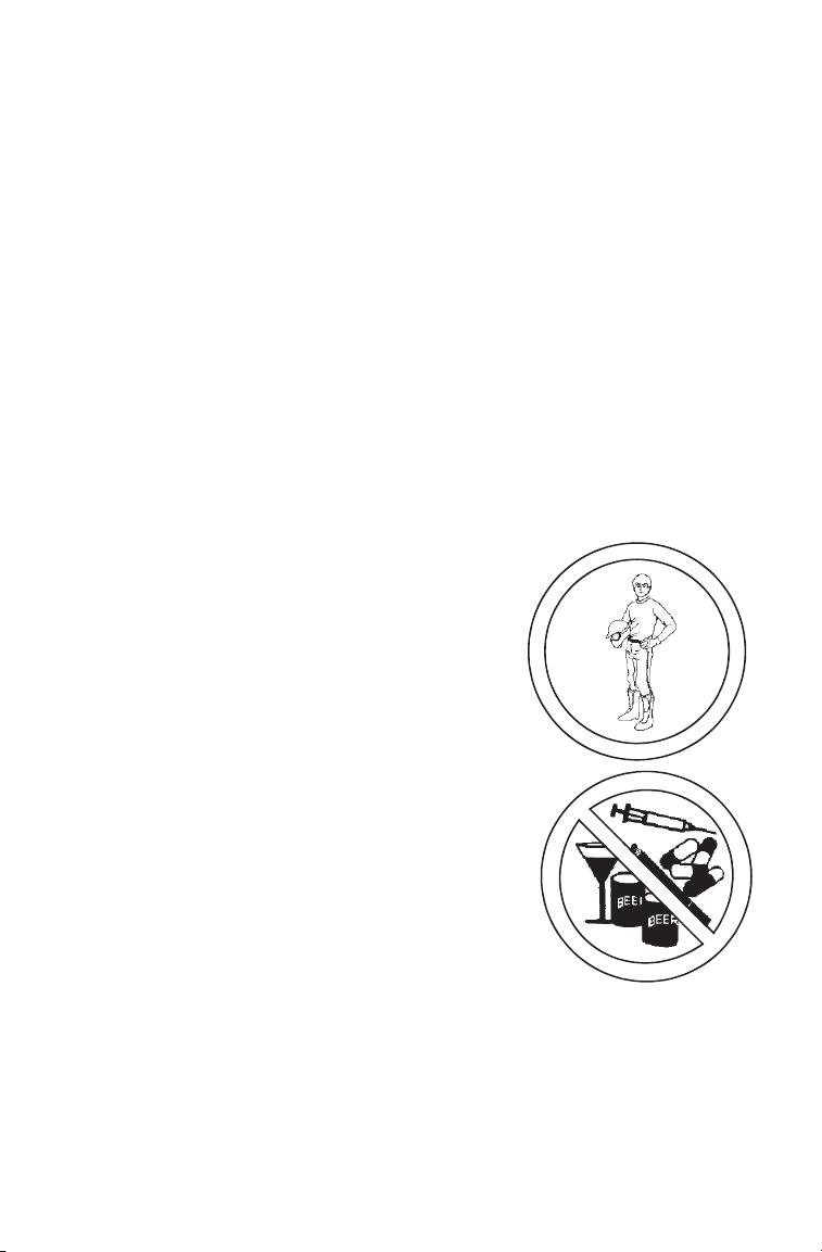
Protective Apparel
Riding in this vehicle without wearing an
approved helmet and protective eyewear
increases the risk of a serious injuries in the
event of an accident.
Always wear an approved helmet that fits
properly and eye protection (goggles or face
shield).
Using Alcohol or Drugs
Operating the ATV after consuming alcohol or
drugs could adversely affect operator judgment,
reaction time, balance and perception.
Never consume alcohol or drugs before or while
operating an ATV.
11
Page 14
SAFETY
Safety Warnings
Carrying a Passenger
Carrying a passenger greatly reduces the
operator's ability to balance and control the
ATV, which may result in an accident or
overturn.
Never carry a passenger on this ATV.
Operating on Pavement
Operating an ATV on paved surfaces
(including sidewalks, paths, parking lots and
driveways) may adversely affect the
handling of the ATV and could result in loss
of control and accident or overturn.
Avoid operating the A TV on pavement. ATV
tires are designed for off-road use. If it's
unavoidable, travel slowly and avoid sudden
turns or stops.
Operating on Public Roads
Operating this ATV on public streets, roads
or highways could result in a collision with
another vehicle.
Never operate the ATV on any public street,
road or highway, including dirt and gravel
roads. In many states it's unlawful to
operate ATVs on public streets, roads and
highways.
Operating at Excessive
Speeds
Operating the ATV at excessive speeds
increases the operator's risk of losing
control.
Always operate at a speed that's
appropriate for the terrain, the visibility and
operating conditions, and your experience.
12
Page 15
Safety Warnings
Physical Control of the ATV
Removing a hand from the handlebars or
feet from the footrests during operation can
reduce your ability to control the vehicle or
cause loss of balance and ejection from the
AT V. If the operator's foot is not firmly
planted on the footrest, it could also contact
the rear wheels.
Never remove your hands from the
handlebars while operating, and always
keep both feet on the footrests.
Turning Improperly
Turning improperly could cause loss of
traction, loss of control, accident or overturn.
Always follow proper procedures for turning
as described in the owner's manual.
Never turn abruptly or at sharp angles. Never
turn at high speeds. Practice turning at slow
speeds before attempting to turn at faster
speeds.
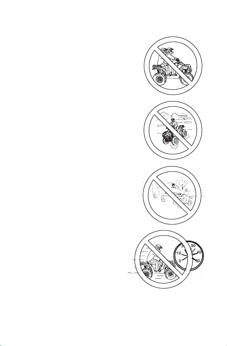
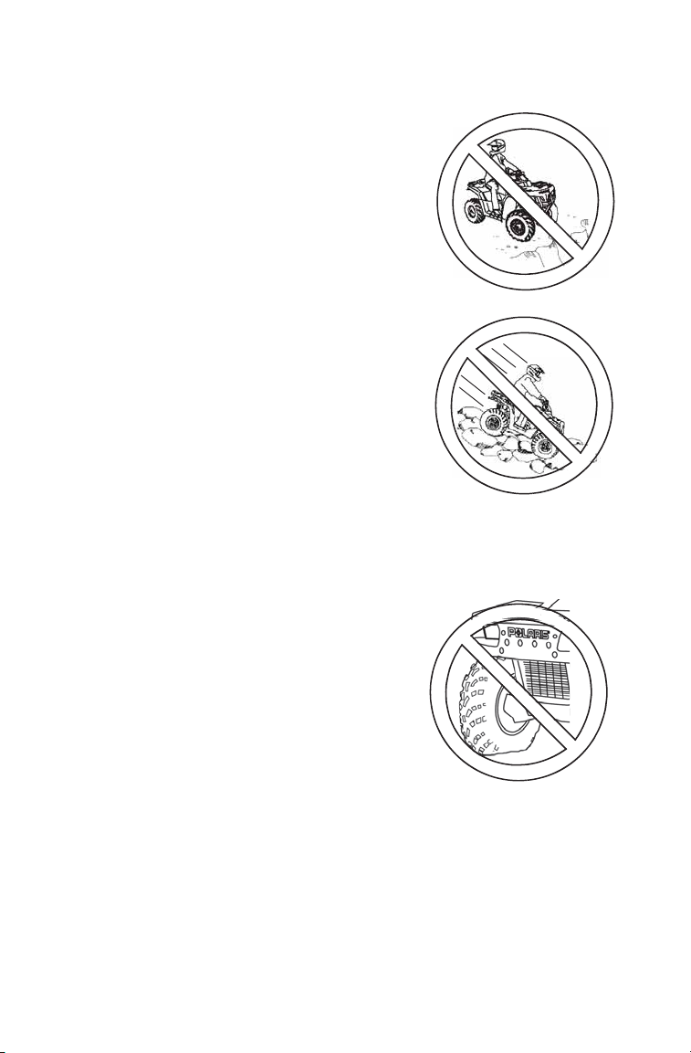
Jumps and Stunts
Attempting wheelies, jumps and other
stunts increases the risk of an accident or
overturn.
Never attempt wheelies, jumps, or other
stunts. Avoid exhibition driving.
SAFETY
Improper Hill Climbing
Improper hill climbing could cause loss of
control or overturn. Always follow proper
procedures for climbing hills as described in
the owner's manual. See page 61. Always
move the 4X4 switch to ADC 4X4 before
ascending or descending a hill.
13
Page 16
SAFETY
Safety Warnings
Descending Hills Improperly
Improperly descending a hill could cause loss
of control or overturn.
• Always follow proper procedures for traveling down hills as described in the owner's
manual. NOTE: A special technique is
required when braking while traveling downhill. See page 63.
• Always descend a hill with the transmission
in forward gear. Do not descend a hill with
the transmission in neutral. Always move the
4X4 switch to ADC 4X4 before ascending or
descending a hill. See page 33.
• Always check the terrain carefull y before descending a hill.
• Shift your weight rearward.
• Never travel down a hill at high speed.
• Avoid traveling down a hill at an angle, which would cause the vehicle to lean
sharply to one side. Travel straight down the hill when possible.
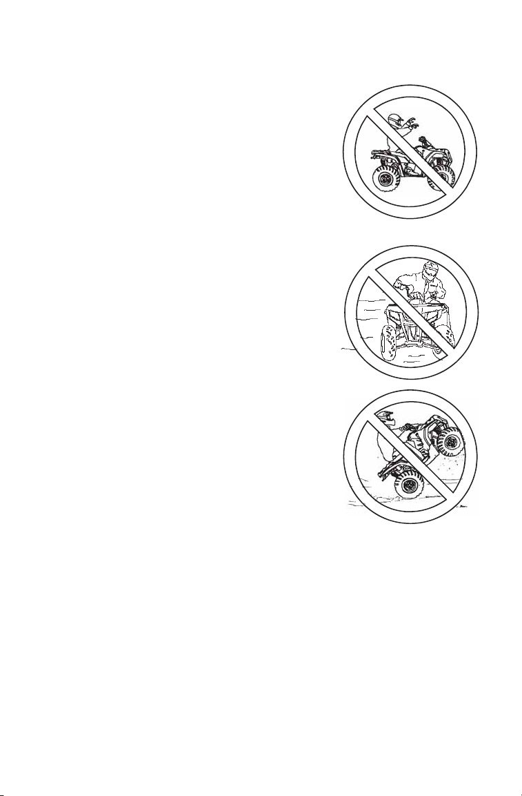
Crossing Hillsides
Driving on a sidehill is not recommended.
Improper procedure could cause loss of control
or overturn. Avoid crossing the side of any hill
unless absolutely necessary.
If crossing a hillside is unavoidable, always follow
proper procedures as described in the owner's
manual. See page 62.
Never attempt to turn the ATV around on any hill
until you've mastered the turning technique (on
level ground) as described in the owner's
manual. See page 64.
14
Page 17
SAFETY
Safety Warnings
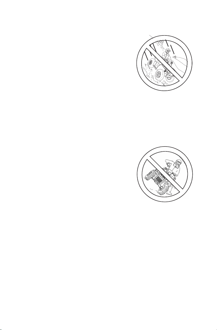
Stalling While Climbing a Hill
Stalling, rolling backwards or improperly
dismounting while climbing a hill could cause an
overturn.
• Always maintain a steady speed when climbing
a hill.
• Always move the 4X4 switch to ADC 4X4 before
ascending or descending a hill. See page 33.
If all forward speed is lost:
• Keep body weight uphill.
• Apply the brakes.
• Lock the parking brake when fully stopped.
• Dismount on uphill side, or to either side if ATV is pointed straight uphill.
• Turn the ATV around and remount, following the procedure described in the
owner's manual. See page 64.
If the ATV begins rolling downhill:
• Keep body weight uphill.
• Never apply engine power.
• Never apply the rear brake while rolli ng backwards. Apply the single-lever
brake gradually.
• When fully stopped, apply the rear brake as well, and then lock the parking
brake.
• Dismount on uphill side, or to either side if ATV is pointed straight uphill.
• Turn the ATV around and remount, following the procedure described in the
owner's manual. See page 64.
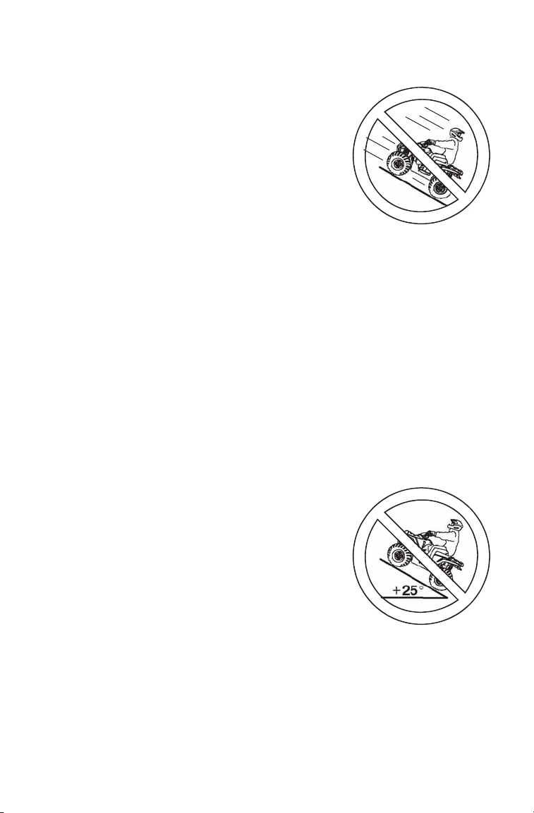
Operating on Steep Hills
Operating on excessively steep hills could cause
an overturn.
Never operate on hills too steep for the ATV or for
your abilities. Never operate the ATV on hills
steeper than 25 degrees.
15
Page 18
SAFETY
Safety Warnings
Operating in Unfamiliar Terrain
Failure to use extra caution when operating on
unfamiliar terrain could result in an accident or
overturn.
Unfamiliar terrain may contain hidden rocks,
bumps, or holes that could cause loss of control or
overturn.
Travel slowly and use extra caution when operating
on unfamiliar terrain. Always be alert to changing
terrain conditions.
Operating on Slippery Terrain
Failure to use extra caution when operating on
excessively rough, slippery or loose terrain could
cause loss of traction, loss of control, accident or
overturn.
Do not operate on excessively rough, slippery or
loose terrain. Always use extra caution on rough,
slippery or loose terrain.
Operating Improperly in Reverse
Improperly operating in reverse could result in a
collision with an obstacle or person. Always follow
proper operating procedures as outlined in this manual. See page 67.
Before shifting into reverse gear, always check for obstacles or people behind
the ATV. When it's safe to proceed, back slowly.
Improper Tire Maintenance
Operating this ATV with improper tires
or with improper or uneven tire
pressure could cause loss of control or
accident.
Always use the size and type of tires
specified for your ATV.
Always maintain proper tire pressure as
described in the owner's manual and
on safety labels.
16
Page 19

SAFETY
Safety Warnings
Operating Over Obstacles
Improperly operating over obstacles could cause loss of control or overturn.
Before operating in a new area, check for obstacles. Avoid operating over large
obstacles such as rocks and fallen trees. If unavoidable, use extreme caution
and always follow proper operating procedures as outlined in this manual. See
page 66.
Skidding or Sliding
Skidding or sliding can cause loss of control or overturn (if tires regain traction
unexpectedly).
On slippery surfaces such as ice or loose gravel, travel slowly and use extra
caution to reduce the chance of skidding or sliding. Do not operate on
excessively slippery surfaces.
Operating Through Deep Water
Operating the ATV through deep or fastflowing water could cause the tires to float,
causing loss of control or overturn.
Avoid operating the ATV through deep or
fast-flowing water. If it's unavoidable to
enter water that exceeds the
recommended maximum depth (see page
65):
• Travel slowly.
• Balance your weight carefully.
• Avoid sudden movements.
• Maintain a slow and steady forward motion. Do not make sudden turns or
stops, and do not make sudden throttle changes.
• Wet brakes may have reduced stopping ability. After leaving water, test the
brakes. Apply them lightly several times while driving slowly. The friction will
help dry out the pads.
17
Page 20

SAFETY
Safety Warnings
Improper Cargo Loading
Overloading the ATV or carrying/towing cargo improperly may cause changes in
handling, which could cause loss of control or an accident.
• Never exceed the stated load capacity for this ATV.
• Cargo should be properly distributed and securely attached.
• Reduce speed when carrying cargo or pulling a tra iler. Allow a greater distance for braking.
• NEVER exceed 50 MPH (80 km/h) when rear cargo loads are above 75 lbs.
(34 kg) and/or front cargo loads are above 37 lbs. (17 kg).
• NEVER exceed 10 MPH (16 km/h) when rear cargo loads are above 200 lbs.
(91 kg) and/or front cargo loads are above 100 lbs. (45 kg).
• Always follow the instructions in the owner's manual for carrying cargo or pulling a trailer. See pages 68-69.
Operating on Frozen Bodies of Water
Operating on frozen bodies of water may result in serious injury or death if the
ATV and/or the operator fall through the ice.
Never operate the ATV on a frozen body of water unless you have
independently verified that the ice is sufficiently thick to support the weight and
moving force of the ATV, you and your cargo, together with any other vehicles in
your party. Varian ces in snow dep th and/or water currents may result in uneven
ice thickness. Always check with local authorities and residents to confirm ice
conditions and thickness over your entire route. ATV operators assume all risk
associated with ice conditions on frozen bodies of water.
Poor Visibility
Operating the ATV in darkness or inclement weather could result in a collision or
accident, especially if operating on a road or street. This ATV is not equipped
with highway-approved lights. Operate this vehicle off-road only. Use caution
and drive at reduced speeds in conditions of reduced visibility such as fog, rain
and darkness. Clean headlights frequently and replace burned out headlamps
promptly.
18
Page 21

SAFETY
Safety Warnings
Operating a Damaged ATV
Operating a damaged ATV can result in an accident. After any overturn or
accident, have a qualified service dealer inspect the entire machine for possible
damage, including (but not limited to) brakes, throttle and steering systems.
Physical Skills
Safe operation of this rider-active vehicle requires good judgement and physical
skills. Persons with cognitive or physical disabilities who operate this vehicle
have an increased risk of overturn and loss of control.
Hot Exhaust Systems
Exhaust system components are very hot during and after use of the vehicle.
Hot components can cause burns and fire. Do not touch hot exhaust system
components. Always keep combustible materials away from the exhaust
system. Use caution when traveling through tall grass, especially dry grass.
Unauthorized Use of the ATV
Leaving the keys in the ignition can lead to unauthorized use of the vehicle,
which could result in an accident or overturn. Always remove the ignition key
when the vehicle is not in use.
19
Page 22

SAFETY
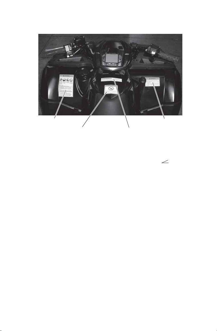
Safety Labels and Locations
Warning labels have been placed on the vehicle for your protection.
Read and follow the instructions on each label carefully. If any of the
labels shown in this manual differ from the labels on your vehicle,
always read and follow the instructions of the labels on the vehicle.
If an informational or graphic label becomes illegible or comes off, contact your POLARIS dealer to purchase a replacement. Replacement
safety labels are provided by POLARIS at no charge. The part number is
printed on the label.
General Warning
WARNING
Improper ATV use can result in SEVERE INJURY or DEATH
ALWAYS USE AN APPROVED HELMET AND PROTECTIVE GEAR
NEVER USE ON PUBLIC ROADS
NEVER CARRY PASSENGERS
NEVER USE WITH DRUGS OR ALCOHOL
NEVER operate:
• without proper training or instruction
• at speeds too fast for your skills or the conditions
• on public roads - a collision can occur with anoth er vehicle
• with a passenger - passengers affect balance and steering and increase risk
of losing control
ALWAYS:
• use proper riding techniques to avoid vehicle overturns on hills and rough terrain and in turns
• avoid paved surfaces - pavement may seriously affect handling and control
LOCATE AND READ OWNER’S MANUAL.
FOLLOW ALL INSTRUCTIONS AND WARNINGS.
7175376
20
Page 23
SAFETY
Discretionary WarningGeneral Warning
Reverse Override Warning
4X4 Caution
Age 16 Warning
Safety Labels and Locations
Discretionary Warning
WARNING
• Never operate this ATV on HILLS steeper than 25 degrees 25°. To pre-
vent overturn on hilly terrain, use throttle and brakes gradually, and shift
weight uphill.
• REVERSE operation can be dangerous even at low speeds. Steering
becomes difficult. To prevent loss of control, avoid sudden braking or sharp
turns.
7175511
Age 16 Warning
WARNING
Operating this ATV if you are under the age of 16 increases your chance of
severe injury or death.
NEVER operate this ATV if you are under age 16.
7175374
Reverse Override Warning/4X4 Caution
WARNING
Improper use of the override button can lead to loss of control resulting in severe
injury or death. Do not activate override while throttle is engaged. Always apply
throttle gradually, while in reverse.
CAUTION
Do not push switch to engage 4X4 (AWD) if the rear wheels are spinning. This
may cause severe drive shaft and clutch damage.
7175512
21
Page 24
SAFETY
“No Passenger”
Warning
Tire
Pressure/Load
Warning
Safety Labels and Locations
“No Passenger” Warning
WARNING
NEVER ride as a passenger.
Passengers can cause a loss of control, resulting in SEVERE INJURY or
DEATH.
Tire Pressure/Load Warning
WARNING
Improper tire pressure or overloading can cause loss of control.
Loss of control can result in severe injury or death.
• Cold tire pressure:
Front: 7.0 psi (48.3 kPa)
Rear: 7.0 psi (48.3 kPa)
• Maximum weight capacity: 575 lbs. (261 kg)
• Lug nut torque values:
Steel rims 45 ft-lbs. (61 Nm)
Aluminum rims 75 ft-lbs. (102 Nm)
7175378
22
Page 25

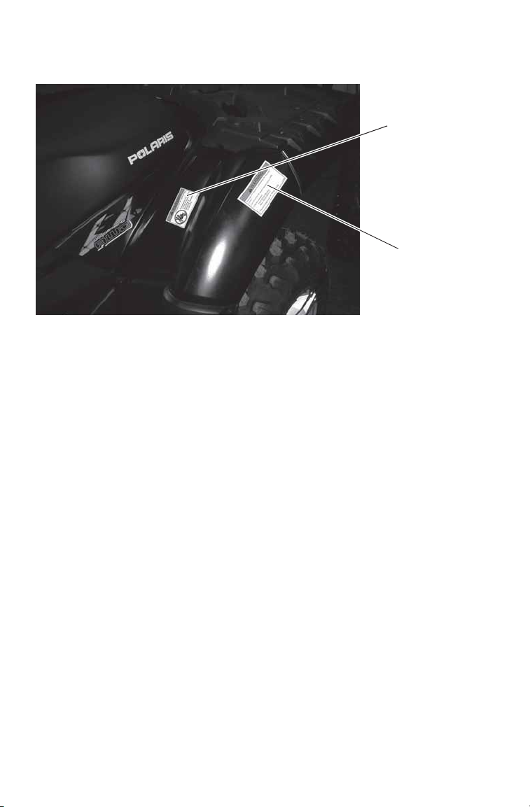
SAFETY
Clutch Cover
Warning
(under seat)
Rack
Warning
Rack
Warning
Safety Labels and Locations
Hitch Capacity
Label
Clutch Cover Warning
WARNING
• Moving parts hazard under belt-clutch guard. To prevent serious injury, do not
operate vehicle with guard removed.
• Do not modify engine or clutch. Doing so can cause part failure, possible
imbalance, and excessive engine RPM, which can result in serious injury or
death.
Rack Warning, Front and Rear
WARNING
• DO NOT TOW FROM RACK OR BUMPER. Vehicle damage or tipover may
result causing severe injury or death. Tow only from tow hooks or hitch.
• Max. Rack Loads: Front 120 lbs. (54 kg) Rear 240 lbs. (109 kg)
Hitch Capacity Label
TRAILER MAX WEIGHT:
1500 LBS. (682 KG) ON LEVEL GROUND
850 LBS. (386 KG) UP TO 15° GRADE
HITCH MAX. VERTICAL WEIGHT: 150 LBS. (68 KG)
7175488
7175448
7170509
23
Page 26
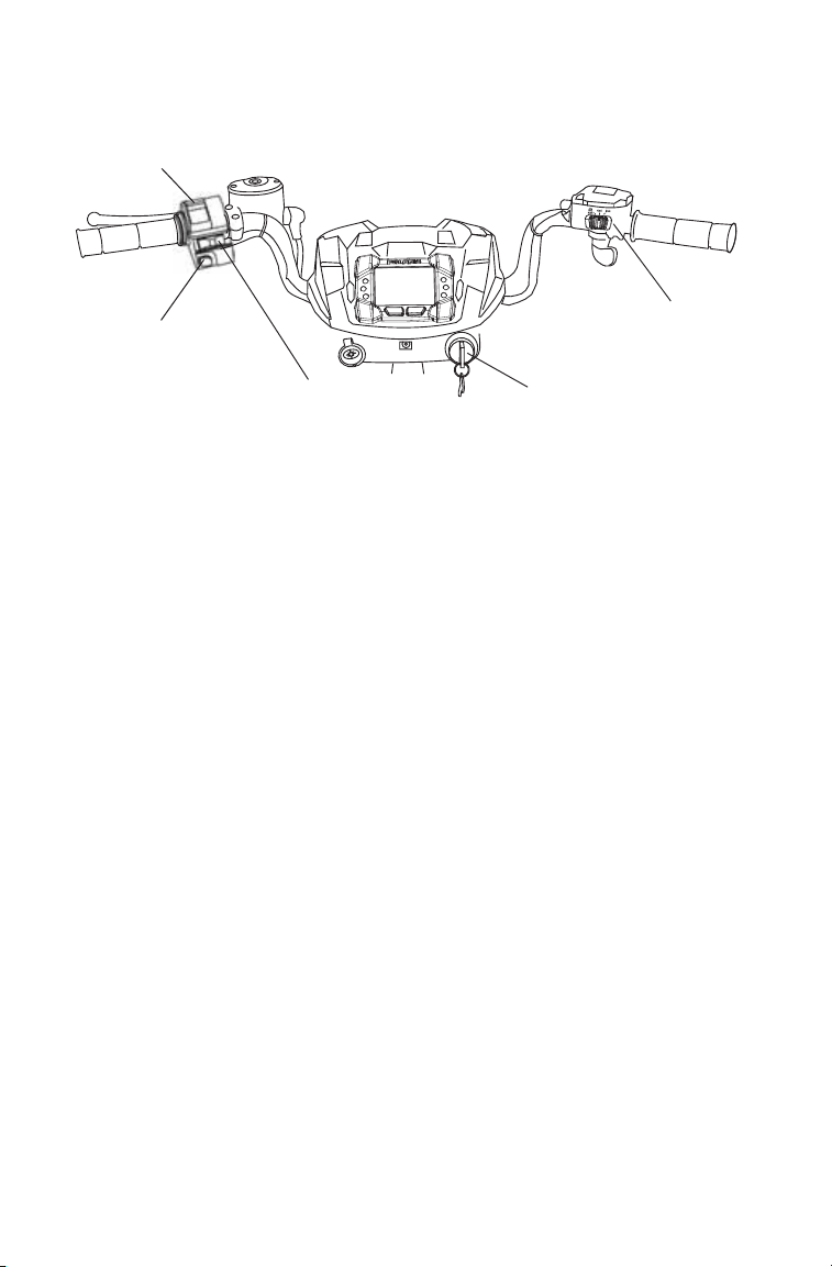
FEATURES AND CONTROLS
Mode/Reverse
Override
Button
Main Key
Switch
Engine
Stop Switch
Headlight
Switch
4X4 Switch
Switches
2x4
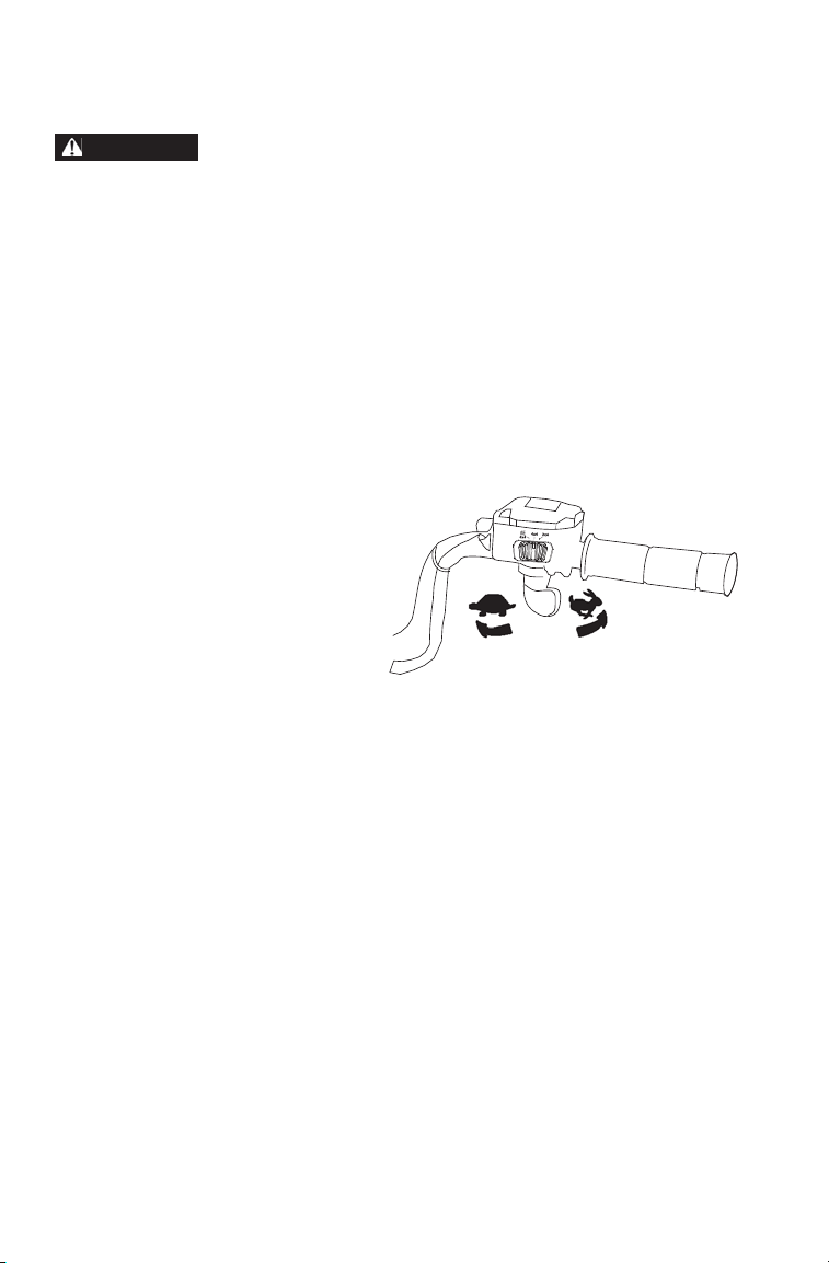
Mode/Reverse Override Switch
This vehicle is equipped with a reverse speed limiter system. To gain
additional wheel speed while backing, release the throttle and depress
the override button.
WARNING! Pressing the override button while the throttle is open can cause
loss of control, which may result in serious injury or death. Always release the
throttle before pressing the override button.
The reverse override button also acts as a MODE button when held
down for approximately one half second. See the instrument cluster
information beginning on page 34. The transmission cannot be in
reverse when using the override button as a MODE button.
4X4 Switch
Use the 4X4 switch to engage ADC 4X4, 4X4 or 2X4. See page 33. The
vehicle automatically engages 4X4 when operating in reverse if the
switch is set to either 4X4 position.
Headlight Switch
Use the headlight switch to turn the lights on and off and to change the
lights from high beam to low beam. The key must be in the ON position
and the engine stop switch must be in the RUN position to operate the
headlights.
24
Page 27
FEATURES AND CONTROLS
Gear
Selector
Switches
Engine Stop Switch
Move the stop switch either
left or right to the OFF position
to stop the engine quickly.
Move the stop switch to the
RUN position before attempting to start the engine. The engine will not start or run when the switch
is off.
Both the main switch and the engine stop switch will shut off all electrical power to the vehicle, including lights.
Main Key Switch
Use the main key switch to start the engine. See page 57 for starting procedures.
Automatic Transmission Gear Selector
The transmission gear selector is
located on the right side of the vehicle.
H: High Gear
L: Low Gear
N: Neutral
R: Reverse
P: Park
To shift gears, brake to a complete stop. When the engine is idling,
move the lever to the desired gear.
NOTICE: Shifting gears with the engine speed above idle or while the vehicle is
moving could cause transmission damage.
Whenever the ATV is left unattended, always place the transmission in
PARK and lock the parking brake.
OFF OFFRUN
Belt Life
To extend belt life, use low forward gear when pulling a heavy load at
less than seven miles per hour for extended periods and when operating
uphill at a slow speed.
25
Page 28
FEATURES AND CONTROLS
WARNING
Throttle Lever
Operating an ATV with sticking or improperly operating throttle controls could
cause an accident. Never start or operate an ATV that has a sticking or
improperly operating throttle. Always contact your dealer for service before
operating the vehicle.
Failure to check or maintain proper operation of the throttle system can result in
an accident if the throttle lever sticks during operation. Always check the lever
for free movement and return before starting the engine. Also check
occasionally during operation.
Modifications to the throttle release switch could result in failure to perform as
designed, which could result in an accident. Do not attempt to modify the throttle
release switch or replace it with any after market throttle mechanisms. Always
ensure that the throttle cable is installed and properly routed to the throttle
release switch.
Engine speed and vehicle
movement are controlled by
pressing the throttle lever. The
throttle lever is spring loaded.
Engine speed returns to idle
when the lever is released.
This ATV is equipped with a
throttle release switch, which is
designed to reduce the risk of a
frozen or stuck throttle. If the
throttle cable should stick in an
open position when the operator releases the throttle lever, engine speed
will be limited, and power to the rear wheels will be reduced.
2x4
26
Page 29
FEATURES AND CONTROLS
WARNING
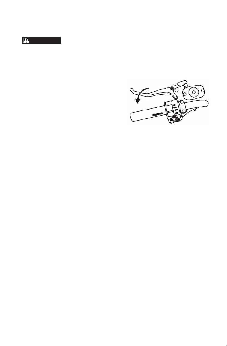
Brake Lever
Operating the ATV with a spongy brake lever can result in loss of braking, which
could cause an accident. Never operate the ATV with a spongy-feeling brake
lever. Always contact your dealer for service before operating the vehicle.
Squeeze the brake lever toward
the handlebar to apply the front
and rear brakes. These brakes are
hydraulically activated disc type
brakes that are activated by only
one lever.
Always test brake lever travel
and master cylinder fluid level
before riding. When squeezed,
the lever should feel firm. Any sponginess would indicate a possible
fluid leak or low master cylinder fluid level, which must be corrected
before riding. Contact your dealer for proper diagnosis and repairs.
27
Page 30
FEATURES AND CONTROLS
WARNING
Master
Cylinder
Indicator
Window
Master Cylinder/Brake Fluid
An over-full master cylinder may cause brake drag or brake lock-up, which could
result in an accident. Maintain brake fluid at the recommended level. Do not
overfill.
Never store or use a partial bottle of brake fluid. Brake fluid is hygroscopic,
meaning it rapidly absorbs moisture from the air. The moisture causes the
boiling temperature of the brake fluid to drop, which can lead to early brake fade
and the possibility of brake failure, which could result in an accident. After
opening a bottle of brake fluid, always discard any unused portion.
Check the brake fluid in the
master cylinder before each ride.
1. Position the ATV on a level
surface.
2. Position the handlebars so
the master cylinder is level.
3. View the brake fluid level
through the indicator window on the top of the master
cylinder. The eye will
appear dark when the fluid
level is full. When fluid is
low, the eye will be clear.
4. If the fluid level is low , remove the cover screws and add fluid to the
fill line. Do not overfill. Use DOT 4 brake fluid only.
5. Reinstall the cover. Torque screws to 7 in. lbs. (.8 Nm).
28
Page 31

FEATURES AND CONTROLS
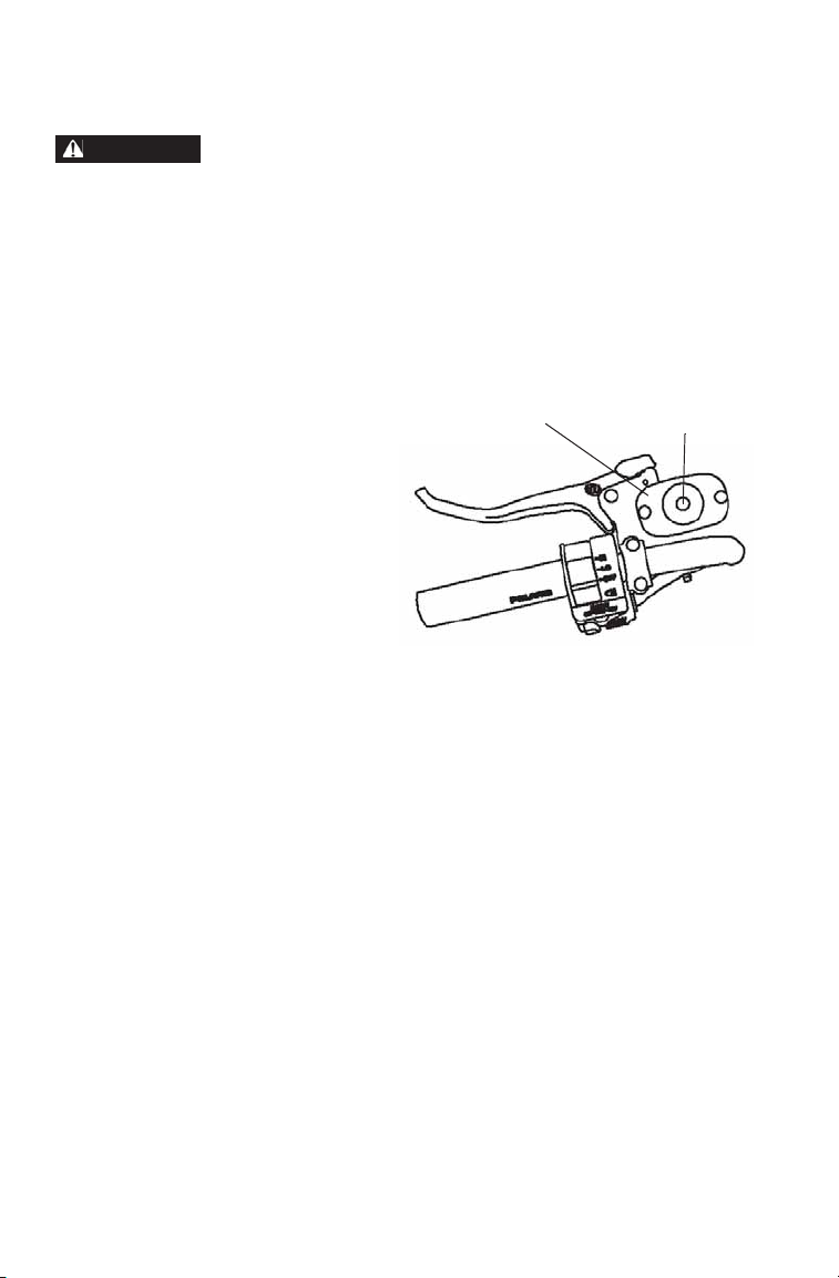
Parking Brake
Locking the Parking Brake
1. Place the transmission in
PARK.
2. Squeeze and release the brake
lever two or three times, then
squeeze and hold.
3. Push the parking brake lock
forward to engage the lock.
4. Release the brake lever.
5. To release the parking brake lock, squeeze and release the brake
lever. It will return to its unlocked position.
WARNING! Operating the ATV while the parking brake is engaged could result
in an accident or fire. Always check to be sure the parking brake is disengaged
before operating.
The parking brake may relax if left on for a long period of time. Always
block the wheels to prevent rolling. Always block the wheels on the
downhill side of the ATV if leaving it parked on a hill. Another option is
to park the ATV in a sidehill position. Never depend on the parking
brake alone if the ATV is parked on a hill. Always block the wheels to
prevent rolling.
29
Page 32

FEATURES AND CONTROLS
WARNING
Auxiliary
Foot Brake
Brake Fluid
Reservoir
Auxiliary Foot Brake
Never back down a hill. Applying the auxiliary brake when backing down a hill
may cause rear tipover, which could result in serious injury or death.
Use caution when applying the auxiliary brake. Do not aggressively apply the
auxiliary brake when going forward. The rear wheels may skid and slide
sideways, causing loss of control and serious injury or death.
The auxiliary brake system is
intended to be used as a backup for
the main brake system. Should the
main system fail, use the auxiliary
foot brake.
The auxiliary foot brake is located
on the inside of the right footrest.
Operate this brake with your right
foot.
If the rear wheels slide while using
the auxiliary brake, reduce brake
pedal pressure to brake the rear
wheels without skidding.
Brake Fluid Level
Check the brake fluid level frequently for the auxiliary brake system. The reservoir is located under
the front rack.
Maintain the fluid level between
the maximum and minimum marks.
Use DOT 4 brake fluid only.
NOTICE: Do not use ADC fluid in the
brake fluid reservoir. ADC
fluid will damage the rubber
components of the brake
system.
30
Page 33

FEATURES AND CONTROLS
Fuel Tank
Cap
Electronic Power Steering (EPS)
Electronic power steering (EPS) engages when the ignition key is turned
to the ON position. EPS remains engaged whether the vehicle is moving
or idle. See page 35 for EPS Warning Indicator information.
Fuel Tank
Always refuel with the engine
stopped, and outdoors or in a well
ventilated area. Refuel on a level surface.
Remove the fuel tank cap and add
fuel. Use either leaded or unleaded
gasoline with a minimum pump
octane number of 87=(R+ M/2)
octane. Do not use fuel with ethanol
content greater than 10%, such as E85 fuel.
The fuel tank is designed to allow for
the normal expansion of fuel. Do not
overfill. Do not fill the tank neck.
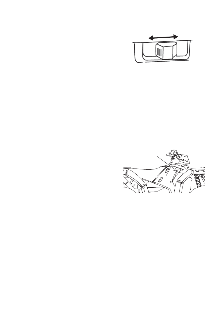
Extreme Use 30 AH Battery
If your factory-installed 18 AH battery cannot maintain a charge
because of operation in extreme cold or with multiple electrical accessories, please see your POLARIS dealer to purchase a 30 AH battery.
1. Fully charge the new battery before installing it. See page 126.
2. To install the 30 AH battery, remove the 18 AH battery. See page
124.
3. Remove the plastic spacer at the bottom of the battery compartment.
Save the spacer for future use.
4. Install the new battery. See page 125.
31
Page 34

FEATURES AND CONTROLS
2x4
All Wheel Drive System
The All Wheel Drive system is
controlled by the 4X4 switch.
ADC 4X4 Mode
When the switch is on ADC 4X4,
the ADC system allows engine
braking to all four wheels when
the vehicle descends a hill or
incline. Always move the 4X4
switch to ADC 4X4 before
ascending or descending a hill.
See page 33.
4X4 Mode
When the switch is on 4X4, the
ATV is in 4X4, and the 4X4 indicator icon in the instrument cluster display will be visible.
When in 4X4, the demand drive
unit will automatically engage
any time the rear wheels lose
traction. When the rear wheels
regain traction, the demand drive
unit will automatically disengage.
There is no limit to the length of time the vehicle may remain in 4X4.
The vehicle automatically engages 4X4 when operating in reverse if the
switch is set to either 4X4 position.
ADC 4X4
4X4
Switch
2X4 Mode
When the switch is on 2X4, the ATV is in two-wheel drive at all times.
32
Page 35

FEATURES AND CONTROLS
All Wheel Drive System
Engaging 4X4
The 4X4 switch may be turned on or off while the vehicle is moving.
Initially, the vehicle's electronic system will not enable 4X4 until the
engine RPM is below 3100. Once enabled, 4X4 remains enabled until
the 4X4 switch is turned off. If the switch is turn ed off while the demand
drive unit is moving, it will not disengage until the rear wheels regain
traction.
Engage the 4X4 switch before getting into conditions where front wheel
drive may be needed. If the rear wheels are spinning, release the throttle
before switching to 4X4.
NOTICE: Switching to 4X4 or ADC 4X4 while the rear wheels are spinning may
Active Descent Control (ADC) System
The ADC system allows engine braking to all four wheels when the
vehicle descends a hill or incline. Always move the 4X4 switch to ADC
4X4 before ascending or descending a hill.
Engaging Active Descent Control
The ADC system will automatically engage when all four of the following conditions occur:
• The 4X4 switch must be in the ADC 4X4 position
• Vehicle speed must be 15 mph (25 km/h) or less
• The throttle must be closed (throttle lever released)
• The transmission must be in gear (high, low or reverse)
cause severe drive shaft and gearcase damage. Always switch to
4X4 or ADC 4X4 while the rear wheels have traction or are at rest.
Disengaging Active Descent Control
The ADC system will automatically disengage if at least one of the following conditions occur:
• The 4X4 switch is moved out of the ADC 4X4 position
• Vehicle speed exceeds 15 mph (25 km/h)
• The throttle is open (throttle is applied)
• The transmission is shifted to neutral or park
33
Page 36

FEATURES AND CONTROLS
Rider
Information
Center
Speedometer
Indicator Lamps
Instrument Cluster
NOTICE: High water pressure may damage ATV components. Wash the ATV
Digital/Analog Gauge
Speedometer
The speedometer displays vehicle speed in either miles per hour (MPH)
or kilometers per hour (km/h).
by hand or with a garden hose using mild soap.
Certain products, including insect repellents and chemicals, will
damage the speedometer lens and other plastic surfaces. Do not use
alcohol to clean the instrument cluster. Do not allow insect sprays to
contact the lens. Immediately clean off any gasoline that splashes on
the instrument cluster.
FE
Trip 1
RPM
km
mi
88:88
34
Page 37

FEATURES AND CONTROLS
Instrument Cluster
Digital/Analog Gauge
Indicator Lamps
Lamp Indicates Condition
Vehicle
Speed
Over
Temperature
EPS Warning This indicator illuminates when the key is turned to
Neutral This lamp illuminates when the transmission is in
High Beam This lamp illuminates when the headlamp switch is
Check Engine This indicator appears if an EFI-related fault occurs.
When standard mode is selected, speed displays in
miles per hour.
When metric mode is selected, speed displays in
kilometers per hour.
This lamp flashes to indicate an overheated engine. If
the indicator stops flashing but remains illuminated,
the overheating condition remains, and the system
will automatically reduce engine power.
the ON position and goes off when the engine is
started. If the light remains on after starting the
engine, the EPS system is inoperative. See your
authorized POLARIS dealer for service.
neutral and the ignition key is in the ON position.
set to high beam.
Do not operate the ATV if this warning appears.
Serious engine damage could result. See your dealer.
35
Page 38

FEATURES AND CONTROLS
Trip 1
km
mi
RPM
EF
88
:
88
Instrument Cluster
Digital/Analog Gauge
Rider Information Center
The rider information center is located in the instrument cluster . All segments will light up for one second at start-up. If the instrument cluster
fails to illuminate, a battery over-voltage may have occurred and the
instrument cluster may have shut off to protect the electronic speedometer. If this occurs, take the ATV to your POLARIS dealer for proper
diagnosis.
The information center is set to display standard units of measurement
and a 12-hour clock at the factory . To change to metric and/or a 24-hour
clock, see page 39.
2
1
6
7
36
5
3
4
Page 39

FEATURES AND CONTROLS
Instrument Cluster
Digital/Analog Gauge
Rider Information Center
1. Gear Display - This area displays gear shifter position.
H = High Gear
L = Low Gear
N = Neutral
R = Reverse Gear
P = Park
-- = Gear Signal Error (or shifter between gears)
2. Fuel Gauge Display - The segments of the fuel gauge show the
level of fuel in the fuel tank. When the last segment clears, a low
fuel warning is activated. All segments including the fuel icon will
flash. Refuel immediately.
Tip: If the fuel icon fails to display, an open or short circuit has occurred in the
fuel sensor circuit. See your dealer.
3. Information Display - This area displays odometer, trip meter,
engine hour meter, engine speed and programmable service hour
interval.
4. Active Descent Control Display - This icon displays when ADC is
active. See page 33.
5. Clock Display - The clock displays time in a 12-hour or 24-hour
format. If the engine is turned off, press the MODE button. The
time will display for 5-10 seconds. See page 39 for resetting instructions.
6. Service Reminder Display - A flashing wrench symbol alerts the
operator that the preset service interval has been reached. The vehicle should be brought to your dealer for scheduled maintenance. See
page 39 for resetting instructions.
7. 4X4 Display - This icon displays when the 4X4 system is engaged
(switch is on either ADC 4X4 or 4X4).
37
Page 40

FEATURES AND CONTROLS
Instrument Cluster
Digital/Analog Gauge
Rider Information Center
The reverse override button acts as the MODE button when pressed and
released quickly. The transmission cannot be in reverse when using the
override button as a MODE button. This feature does not contain a vehicle speed lockout function and can be used at any operating speed.
Display Units (Standard/Metric)
The display can be changed to display either standard or metric units of
measurement.
Tip: To exit the set-up mode at any time, wait 10 seconds.The display automati-
cally exits and returns to the odometer display.
Standard Display Metric Display
Distance Miles Kilometers
Time 12-Hour Clock 24-Hour Clock
1. Turn the key to the OFF position.
2. Place the transmission in neutral.
3. Press and hold the MODE button while turning the key to the ON
position.
4. When the display flashes the distance setting, tap the MODE button
to advance to the desired setting.
5. Press and hold the MODE button to save the setting and advance to
the next display option.
6. Repeat the procedure to change remaining display settings.
38
Page 41

FEATURES AND CONTROLS
Instrument Cluster
Digital/Analog Gauge
Rider Information Center
Clock Mode
Tip: The clock must be reset any time the battery has been disconnected or dis-
charged.
1. Turn the key to the ON position. Use the MODE button to toggle to
the odometer display.
2. Press and hold the MODE button until the hour segment flashes.
Release the button.
3. With the segment flashing, tap the MODE button to advance to the
desired setting.
4. Press and hold the MODE button until the next segment flashes.
Release the button.
5. Repeat steps 3-4 twice to set the 10-minute and 1-minute segments.
After completing the 1-minute segment, step 4 will save the new
settings and exit the clock mode.
6. Turn the key to the OFF position.
Odometer Mode
The odometer records and displays the distance traveled by the ATV.
Trip Meter Mode
The trip meter records the distance traveled by the ATV if reset before
each trip. T o reset, select the trip meter mode. Press and hold the MODE
button until the meter resets to zero. In the Rider Information Center, the
trip meter display contains a decimal point, but the odometer displays
without a decimal point.
Hour Meter Mode
This mode logs the total hours the engine has been in operation.
39
Page 42

FEATURES AND CONTROLS
Instrument Cluster
Digital/Analog Gauge
Rider Information Center
Programmable Service Interval
When the hours of engine operation equal the programmed service
interval setting, the wrench icon will flash for 5 seconds each time the
engine is started. When this feature is enabled, it provides a convenient
reminder to perform routine maintenance. The service interval is programmed at 50 hours at the factory. Use the following procedure to
change the service interval.
1. Press the MODE button until remaining service hours display.
2. Press and hold the MODE button.
3. When the service hours flash, press and release the MODE button to
advance the hours to the desired setting (including OFF). Press and
hold the MODE button to set the new service hour interval.
Diagnostic Display Mode
The EFI diagnostic display mode is for informational purposes only.
Please see your POLARIS dealer for all major repairs.
The diagnostic mode is accessible only when the check engine warning
indicator activates after the key has been turned on. Leave the key on if
you want to view the active code (failure code).
The diagnostic mode becomes inaccessible if the key is turned off and
on and the warning indicator is no longer active. This allows the determination of persistent as well as intermittent faults.
Inactive codes are stored in the history of the unit.
40
Page 43

Instrument Cluster
Suspect Parameter
Number (SPN)
Error Code
Number (0-9)
Failure Mode Indicator (FMI)
Digital/Analog Gauge
Rider Information Center
Engine Error Codes
The error screen displays
only when the CHECK
ENGINE light is on or when
it goes on and off during one
ignition cycle. Error codes
are not stored in the gauge
when the key is turned off.
The code and message is
lost, but will reappear if the
fault reoccurs after restarting the engine.
If the CHECK ENGINE
light illuminates, retrieve
the error codes from the display . Please see your Polaris
dealer for all major repairs.
1. If the error codes are not displayed, use the MODE button to toggle
2. Press and hold the MODE button to enter the diagnostics code
3. Record the numbers displayed in the gear position (if any), clock
4. Press the MODE button to advance to the next error code.
5. Press and hold the MODE button to exit the diagnostics code menu.
6. See pages 48-51 for code definitions and failure descriptions. Please
FEATURES AND CONTROLS
until “Ck ENG” displays on the main line of the display.
menu.
and odometer displays.
see your Polaris dealer for all major repairs.
41
Page 44

FEATURES AND CONTROLS
1
3
4
8
7
5
9
6
10
11
2
5
6
12
13
Instrument Cluster
Multi-Function Display (MFD) Gauge (EPS Models)
The rider information center is located in the
instrument cluster. All segments will light up
for one second at start-up. If the instrument
cluster fails to illuminate, a battery over-voltage may have occurred and the cluster may
have shut down to protect the electronic speedometer. If this occurs, take the ATV to your
Polaris dealer for proper diagnosis.
The information center is set to display standard units of measurement
and a 12-hour clock at the factory . To change to metric and/or a 24-hour
clock, see page 45.
1. Gear Display -
This area displays
gear shifter position.
H = High Gear
L = Low Gear
N = Neutral
R = Reverse Gear
P = Park
-- = Gear Signal
Error (or shifter
between gears)
2. Information
Display - This area
displays odometer,
tripmeters, engine
hour meter and programmable service hour interval.
3. Speed Display - This area displays vehicle ground speed or engine
speed. See page 44.
42
Page 45

FEATURES AND CONTROLS
Instrument Cluster
Multi-Function Display (MFD) Gauge (EPS Models)
4. Fuel Gauge - The segments of the fuel gauge show the level of fuel
in the fuel tank. When the last segment clears, a low fuel warning is
activated. All segments including the fuel icon will flash. Refuel
immediately.
Tip: If the fuel icon fails to display, an open or short circuit has occurred in the
fuel sensor circuit. See your dealer.
5. High Beam Indicator - This indicator illuminates when the lights
are set to high beam.
6. Engine Overheat Warning - This icon flashes to indicate an over-
heated engine. If the icon stops flashing but remains illuminated,
the overheating condition remains, and the system will automatically reduce engine power.
7. Clock Display - The clock displays time in a 12-hour or 24-hour
format. If the engine is turned off, press the MODE button. The
time will display for 5-10 seconds. See page 46 for resetting instructions.
8. Service Reminder Display - A flashing wrench symbol alerts the
operator that the preset service interval has been reached. The vehicle should be brought to your dealer for scheduled maintenance. See
page 46 for resetting instructions.
9. Under / Over Voltage - This warning usually indicates that the
ATV is operating at an RPM too low to keep the battery charged. It
may also occur when the engine is at idle and high electrical load
(lights, cooling fan, accessories) is applied. Drive at a higher RPM
or recharge the battery to clear the warning.
10. Check Engine Warning - This icon displays if an EFI-related fault
occurs. Do not operate the ATV if this warning appears. Serious
engine damage could result. See your dealer.
11. 4X4 Display - This icon displays when the 4X4 system is engaged
(switch is on either ADC 4X4 or 4X4).
12. Neutral Indicator - This indicator illuminates, in addition to dis-
playing in the gear indicator display, when the transmission is in
neutral.
13. EPS Warning Indicator - If this indicator light remains on after
starting the engine, the EPS system is inoperative. See your authorized Polaris dealer for service.
43
Page 46

FEATURES AND CONTROLS
MODE
Button
SELECT
Button
Instrument Cluster
Multi-Function Display (MFD) Gauge (EPS Models)
Use the MODE button to toggle
through the speed display options.
Use the SELECT button (SEL) to
toggle through the information area
options.
MODE and SELECT button operation is locked out at speeds above
approximately 15 MPH (25 km/h).
Tip: The reverse override button also
acts as a MODE button when held
down for approximately one half
second. The reverse override button also acts as the SELECT button when pressed and released
quickly. The transmission cannot be in reverse when using the override button as a MODE or SELECT button. This feature does not contain a vehicle
speed lockout function and can be used at any operating speed.
Speed Display
Use the MODE button to toggle through the speed display options.
Ground speed is displayed in either miles per hour (MPH) or kilometers
per hour (km/h).
Engine speed is displayed in revolutions per minute (RPM).
44
Page 47

FEATURES AND CONTROLS
Instrument Cluster
Multi-Function Display (MFD) Gauge (EPS Models)
Display Units (Standard/Metric)
The display can be viewed in either standard or metric units of measurement. To change units:
1. Press and hold the MODE button until vehicle speed is displayed.
2. T oggle through the information area using the SELECT button until
the odometer is displayed.
3. Press and hold the MODE button until the displayed units change.
Release the button.
4. New settings remain until changed using the same procedure.
12-Hour/24-Hour Clock Display
1. Press and hold the MODE button until RPM is displayed.
2. T oggle through the information area using the SELECT button until
the odometer is displayed.
3. Press and hold the MODE button until the clock displays the new
clock format (either 24-hour or 12-hour). Release the button.
4. New settings remain until changed using the same procedure.
Odometer Mode
The odometer records and displays the distance traveled by the ATV.
Trip Meter Mode
The trip meters record the distance traveled by the ATV on each trip if
reset before each trip. To reset a trip meter, select the trip meter 1 or trip
meter 2 mode. Press and hold the MODE button on the instrument cluster until the total changes to 0. In the Rider Information Center, the trip
meter display contains a decimal point, but the odometer displays without a decimal point.
Hour Meter Mode
This mode logs the total hours the engine has been in operation.
45
Page 48

FEATURES AND CONTROLS
Instrument Cluster
Multi-Function Display (MFD) Gauge (EPS Models)
Programmable Service Interval
When the hours of engine operation equal the programmed service
interval setting, the wrench icon will flash for 5 seconds each time the
engine is started. When this feature is enabled, it provides a convenient
reminder to perform routine maintenance. The service interval is programmed at 50 hours at the factory. Use the following procedure to
change the service interval.
1. Press the SELECT button until remaining service hours display.
2. Press and hold the MODE button.
3. When the service hours flash, press and release the SELECT button
to advance the hours to the desired setting (including OFF). When
the digits stop flashing, the interval has been set.
Clock Mode
Use one of the following two methods to reset the clock.
Method 1
1. Select the Hour Meter Mode.
2. Press and hold the mode button on the instrument cluster until the
hour display flashes. Release the button.
3. Press and release the SELECT button to advance the hours.
4. After the hours are set, press and release the MODE button to move
to the minutes. Use the same procedure to reset the minutes.
5. When the digits stop flashing the clock has been set.
Method 2
1. With the key turned off, press and hold the MODE button.
2. While still holding the MODE button, turn the key to the ON posi-
tion.
3. Continue to hold the MODE button until the hour display flashes.
Release the button.
4. Set the time as outlined in steps 3-5 of Method 1.
46
Page 49

FEATURES AND CONTROLS
Instrument Cluster
Multi-Function Display (MFD) Gauge (EPS Models)
Diagnostic Display Mode
The EFI diagnostic display mode is for informational purposes only.
Please see your Polaris dealer for all major repairs.
The diagnostic mode is accessible only when the check engine warning
indicator activates after the key has been turned on. Leave the key on if
you want to view the active code (failure code).
The diagnostic mode becomes inaccessible if the key is turned off and
on and the warning indicator is no longer active. This allows the determination of persistent as well as intermittent faults.
Inactive codes are stored in the history of the unit. Please see your
Polaris dealer to retrieve inactive codes.
Use the following procedure to view active codes that occur when the
key is on.
1. Place the transmission in PARK.
2. Press and release the SELECT button until the flashing check
engine warning indicator appears in the display.
3. A set of two numbers will also appear in the display.
• The 2-6 digit suspect parameter number (SPN) in the information area
indicates which component is generating the fault code.
• The 1-2 digit failure mode indicator (FMI) number in the clock area indicates the fault mode, such as open or short circuit.
4. See pages 48-51 for code definitions and failure descriptions.
Tip: More than one fault may be active. Press and hold the MODE button to tog-
gle through all currently active diagnostic codes.
47
Page 50

FEATURES AND CONTROLS
Instrument Cluster
Diagnostic Display Code Definitions
Open Load: There is a break in the wires that lead to the item listed in
the chart (injector, fuel pump, etc.), or the item has failed.
Short-to-Ground:
control unit and the item listed in the chart.
Shorted Load:
shorted together, or the item has shorted internally.
Short-to-Battery:
the electronic control unit is shorted to a wire at battery voltage.
Component Condition SPN FMI
Throttle Position Sensor
Engine Temperature Sensor
Intake Air Temperature Sensor
Manifold Absolute Pressure Sensor Voltage Too High 102 3
Crankshaft Position Sensor Circuit Fault 636 8
Gear Sensor Signal Voltage Too Low (to Calibrate) 523 4
Injector 1 (MAG) Driver Circuit Open/Grounded 651 5
Ignition Coil Primary Driver 1 (MAG) Driver Open/Grounded 1268 5
Fuel Pump Driver Circuit
Fan Relay Driver Circuit Driver Circuit Open/Grounded 1071 5
The wire is shorted to ground between the electronic
The wires leading to the item listed in the chart are
The wire leading from the item listed in the chart to
SPORTSMAN 550/550EPS Diagnostic Codes
Voltage Too High 51 3
Voltage Too Low 51 4
Voltage Too High 110 3
Voltage Too Low 110 4
Temperature Too High 110 16
Engine Overheat Shutdown 110 0
Voltage Too High 105 3
Voltage Too Low 105 4
Voltage Too Low 102 4
Voltage Too High 523 3
Signal Fault 523 2
Driver Circuit Short to B+ 651 3
Driver Circuit Short to B+ 1268 3
Driver Circuit Open/Grounded 1347 5
Driver Circuit Short to B+ 1347 3
Driver Circuit Short to B+ 1071 3
48
Page 51

FEATURES AND CONTROLS
Instrument Cluster
Diagnostic Display Code Definitions
SPORTSMAN 550/550 EPS Diagnostic Codes
Component Condition SPN FMI
Idle Air Control Driver Circuit Grounded 520193 5
Shorted Load* 520193 11
Starter Enable Circuit Driver Circuit Short to B+ 1321 3
All Wheel Drive Control Driver Circuit Short to B+ 520207 3
System Power Voltage Too High 168 3
Voltage Too low 168 4
Throttle Safety Signal Voltage Too High 520194 3
Voltage Too Low 520194 4
Signal Out of Range 520194 2
Throttle Stuck 520194 7
Active Descent Control System Driver Circuit Short to B+ 520203 3
EPS Models Only
Steering Over Current Shut Down Current Above Normal or
Steering Excessive Current Error Current Above Normal or
Steering Torque Sensor T1 Partial
Failure
Steering Torque Sensor T2 Partial
Failure
Steering Torque Sensor Full Failure T1 and T2 Shorted to Ground 520225 4
Steering Position Sensor P1 Partial
Failure
Steering Position Sensor P2 Partial
Failure
Steering Position Sensor Full Failure P1 and P2 Shorted to Ground 520228 4
EPAS Inverter Temperature Greater than 110 Degrees C 520229 16
EPAS CAN Communications
Receive Error
EPAS CAN Communications
Transmit Error
Grounded
Grounded
T1 Shorted to Ground 520223 4
T1 Shorted to Bus 520223 3
T2 Shorted to Ground 520224 4
T2 Shorted to Bus 520224 3
T1 and T2 Shorted to Bus 520225 3
T1 Shorted to Ground & T2
Shorted to Bus
T2 Shorted to Ground & T1
Shorted to Bus
T1 and T2 are Shorted 520225 2
P1 Shorted to Ground 520226 4
P1 Shorted to Bus 520226 3
P2 Shorted to Ground 520227 4
P2 Shorted to Bus 520227 3
P1 and P2 Shorted to bus 520228 3
Greater than 120 Degrees C 520229 0
No RX Message for 2 Seconds 520230 9
No TX Message for 2 Seconds 520231 9
*Assumes unipolar configuration of stepper motor
520221 6
520222 6
520225 16
520225 17
49
Page 52

FEATURES AND CONTROLS
Instrument Cluster
Diagnostic Display Code Definitions
SPORTSMAN XP 850 / 850 EPS Diagnostic Codes
Component Condition SPN FMI
Throttle Position Sensor Voltage Too High 51 3
Voltage Too Low 51 4
Engine Temperature Sensor Voltage Too High 110 3
Voltage Too Low 110 4
Temperature Too High 110 16
Engine Overheat Shutdown 110 0
Intake Air Temperature Sensor Voltage Too High 105 3
Voltage Too Low 105 4
Manifold Absolute Pressure Sensor Voltage Too High 102 3
Voltage Too Low 102 4
Signal Out of Range 102 2
Crankshaft Position Sensor Circuit Fault 636 8
Plausibility Fault 636 2
Vehicle Speed Signal Speed Too High 84 8
Plausibility Fault 84 2
Gear Sensor Signal Voltage Too Low 523 4
Voltage too high 523 3
Signal fault 523 2
Injector 1 (MAG) (SDI Part Load) Driver Circuit Open/Grounded 651 5
Driver Circuit Short to B+ 651 3
Driver Circuit Grounded 651 4
Injector 2 (PTO) (SDI Part Load) Driver Circuit Open/Grounded 652 5
Driver Circuit Short to B+ 652 3
Driver Circuit Grounded 652 4
Ignition Coil Primary Driver 1 (MAG) Driver Circuit Short to B+ 1268 3
Ignition Coil Primary Driver 2 (PTO) Driver Circuit Short to B+ 1269 3
Fuel Pump Driver Circuit Driver Circuit Open/Grounded 1347 5
Driver Circuit Short to B+ 1347 3
Driver Circuit Grounded 1347 4
Fan Relay Driver Circuit Driver Circuit Open/Grounded 1071 5
Driver Circuit Short to B+ 1071 3
Driver Circuit Grounded 1071 4
Idle Air Control Driver Circuit Open/Grounded 634 5
Driver Circuit Short to B+ 634 3
Driver Circuit Grounded 634 4
Position Out of Range 634 7
Starter Enable Circuit Driver Circuit Open/Grounded 1321 5
Driver Circuit Short to B+ 1321 3
Driver Circuit Grounded 1321 4
50
Page 53

FEATURES AND CONTROLS
Instrument Cluster
Diagnostic Display Code Definitions
SPORTSMAN XP 850 / 850 EPS Diagnostic Codes
Component Condition SPN FMI
Chassis Relay Driver Circuit Open/Grounded 520208 5
Driver Circuit Short to B+ 520208 3
Driver Circuit Grounded 520208 4
All Wheel Drive Control Driver Circuit Open/Grounded 520207 5
Driver Circuit Short to B+ 520207 3
Driver Circuit Grounded 520207 4
System Power Voltage Too High 168 3
Voltage Too low 168 4
Throttle Safety Signal Voltage Too High 520194 3
Voltage Too Low 520194 4
Signal Out of Range 520194 2
Throttle Stuck 520194 7
Active Descent Control System Driver Circuit Open/Grounded 520203 5
Driver Circuit Short to B+ 520203 3
Driver Circuit Grounded 520203 4
Idle Speed Speed Too High 520211 3
Speed Too Low 520211 4
EPS Models Only
Steering Over Current Shutdown Current Above Normal/Grounded 520221 6
Steering Excessive Current Error Current Above Normal/Grounded 520222 6
Steering Torque Sensor T1 Par-
tial Failure
Steering Torque Sensor T2 Par-
tial Failure
Steering Torque Sensor Full
Failure
Steering Position Sensor P1
Partial Failure
Steering Position Sensor P2
Partial Failure
Steering Position Sensor Full
Failure
EPAS Inverter Temperature Greater than 110 Degrees C 520229 16
EPAS CAN Comm. Receive Err No RX Message for 2 Seconds 520230 9
EPAS CAN Comm. Tr ansmit Err No TX Message for 2 Seconds 520231 9
IC CAN Comm. w/EPAS EPAS Offline 520230 31
T1 Shorted to Ground 520223 4
T1 Shorted to Bus 520223 3
T2 Shorted to Ground 520224 4
T2 Shorted to Bus 520224 3
T1 and T2 Shorted to Ground 520225 4
T1 and T2 Shorted to Bus 520225 3
T1 Short to Ground & T2 Short to Bus 520225 16
T2 Short to Ground & T1 Short to Bus 520225 17
T1 and T2 are Shorted 520225 2
P1 Shorted to Ground 520226 4
P1 Shorted to Bus 520226 3
P2 Shorted to Ground 520227 4
P2 Shorted to Bus 520227 3
P1 and P2 Shorted to Ground 520228 4
P1 and P2 Shorted to bus 520228 3
Greater than 120 Degrees C 520229 0
51
Page 54

FEATURES AND CONTROLS
Latches
Front Rack/Compartment
Release the front rack latches
and remove the rack to gain
access to the front compartment. To reinstall the rack,
hold the rack as shown in the
illustration. Position the front
edge in the tabs, then push the
rack downward and secure
the latches.
Access the following
components in the front
compartment:
• Radiator cap
• Brake fluid reservoir
• ADC fluid reservoir
• Battery
• Coolant recovery bottle cap
• Electrical/fuse/relay components
Coolant
Bottle Cap
Radiator
Cap
52
Battery
Brake Fluid
Reservoir
Electrical/Fuse/Relay
ADC Fluid
Reservoir
Page 55

OPERATION
WARNING
Failure to operate the ATV properly can result in a collision, loss of control,
accident or overturn, which may result in serious injury or death. Read and
understand all safety warnings outlined in the safety section of this owner’s
manual.
Break-In Period
The break-in period for your new POLARIS ATV is the first 20 hours of
operation. No single action on your part is as important as following the
procedures for a proper break-in. Careful treatment of a new engine and
drive components will result in more efficient performance and longer
life for these components.
NOTICE: Excessive heat build-up during the first three hours of operation will
Engine and Drivetrain Break-in
1. Fill the fuel tank with gasoline. See page 31. Always exercise
2. Check the engine oil level on the dipstick. See page 89. Add oil if
3. Drive slowly at first. Select an open area that allows room to famil-
4. Vary the throttle positions. Do not operate at sustained idle.
5. Perform regular checks on fluid levels, controls and areas outlined
6. Pull only light loads.
7. Change both the oil and the filter at 25 hours.
8. Check fluid levels of transmission and all gearcases after the first 25
damage close-fitted engine parts and drive components. Do not
operate at full throttle or high speeds during the first three hours of
use.
extreme caution whenever handling gasoline.
necessary to maintain the level between the safe and add marks.
iarize yourself with vehicle operation and handling.
on the daily pre-ride inspection checklist. See page 54.
hours of operation and every 100 hours thereafter.
PVT Break-in (Clutches/Belt)
A proper break-in of the clutches and drive belt will ensure a longer life
and better performance. Break in the clutches and belt by operating at
slower speeds during the break-in period as recommended. Pull only
light loads. Avoid aggressive acceleration and high speed operation during the break-in period.
If a belt fails, always clean away all debris when replacing the belt.
53
Page 56

OPERATION
Pre-Ride Checklist
Failure to inspect and verify that the ATV is in safe operating condition
before operating increases the risk of an accident. Always inspect the
ATV before each use to make sure it's in safe operating condition.
Item Remarks Page
Brake system/lever travel Ensure proper operation 27
Brake fluid Ensure proper level 28
Auxiliary brake Ensure proper operation 30
Front suspension Inspect, lubricate if nece ssary 88
Rear suspension Inspect, lubricate if necessary 88
Steering Ensure free operation Tires Inspect condition and pressure 104
Wheels/fasteners Inspect, ensure fastener tightness 104
Frame nuts, bolts, fasteners Inspect, ensure tightness Fuel and oil Ensure proper levels 31
Coolant level Ensure proper level 99
Coolant hoses Inspect for leaks -
Throttle Ensure proper operation 26
Indicator lights/switches Ensure operation 24
Engine stop switch Ensure proper operation 25
Air filter, pre-filter Inspect, clean 107
Headlamp Check operation 24
Brake light/tail lamp Check operation 113
Riding gear Wear approved helmet, goggles, and
ADC Fluid Ensure proper level 94
protective clothing
101
106
89
100
122
109
8
54
Page 57

OPERATION
Safe Operation Practices
1. Complete the recommended safety training before operating this
vehicle. See page 7.
2. Do not allow anyone under 16 years of age to operate this vehicle.
Do not allow anyone with cognitive or physical disabilities to operate this vehicle.
3. Never carry a passenger on this ATV.
4. Engine exhaust fumes are poisonous. Never start the engine or let it
run in an enclosed area.
5. Before operating, learn how to use the auxiliary brake for emer-
gency situations (if service brakes become inoperable).
6. Operate this vehicle off-road only. Never operate the vehicle on
pavement or on any public street, road or highway, including dirt
and gravel roads.
7. Use caution and drive at reduced speeds in conditions of reduced
visibility such as fog, rain and darkness. Clean headlights frequently and replace burned out headlamps promptly.
8. Drive in a manner appropriate for your skills and operating condi-
tions. Never operate at excessive speeds. Never attempt wheelies,
jumps, or other stunts. Never remove your hands from the handlebars while operating, and always keep both feet on the footrests.
9. Never consume alcohol or drugs before or while operating an ATV.
10. Always use the size and type of tires specified for your vehicle.
Always maintain proper tire pressure.
11. Never operate a damaged A TV. After any overturn or accident, have
a qualified service dealer inspect the entire machine for possible
damage.
12. Never operate the ATV on a frozen body of water unless you have
independently verified that the ice is sufficiently thick to support t he
weight and moving force of the ATV, you and your cargo, together
with any other vehicles in your party.
13. Do not touch hot exhaust system components. Always keep com-
bustible materials away from the exhaust system.
14. Always remove the ignition key when the vehicle is not in use to
prevent unauthorized use.
55
Page 58

OPERATION
Know Your Riding Area/Tread Lightly
Familiarize yourself with all laws and regulations concerning the operation of this off-road vehicle in your area. Respect the environment in
which you ride. Find out where the designated riding areas are by contacting your POLARIS dealer, a local riding club or local officials.
Help keep our trails open for recreational vehicle use. As an off-road
enthusiast, you represent the sport and can set a good example (or a poor
example) for others to follow . T read lightly. Operate with respect for the
terrain, avoid littering, and always stay on the designated trails.
Trail Etiquette
Always practice good etiquette when riding. Allow a safe distance
between your vehicle and other vehicles operating in the same area.
Communicate to oncoming operators by signaling the number of vehicles in your group. When stopping, move your vehicle to the edge of the
trail as far as possible to allow others to pass safely.
56
Page 59

OPERATION
Starting the Engine
1. Position the vehicle on a level surface outdoors or in a well-ventilated area.
2. Place the transmission in PARK.
3. Lock the parking brake.
Tip: The starter interlock will prevent the engine from starting if the transmission
is in gear and the brake is not engaged.
4. Sit on the vehicle and move the engine stop switch to RUN.
5. Do not press the throttle while starting the engine.
6. Turn the ignition key past the ON position to engage the starter.
Activate the starter for a maximum of five seconds, releasing the
key when the engine starts.
7. If the engine does not start, return the key to the OFF position and
wait five seconds before attempting to start again. Activate the
starter for another five seconds if necessary. Repeat this procedure
until the engine starts.
NOTICE: Operating the vehicle immediately after starting could cause engine
Cold Weather Operation
If the ATV is used year-round, check the oil level frequently. A rising oil
level could indicate the accumulation of contaminates such as water or
excess fuel in the bottom of the crankcase. Water in the bottom of the
crankcase can lead to engine damage and must be drained. Water accumulation increases as outside temperature decreases.
damage. Allow the engine to warm up for several minutes before
operating the vehicle.
57
Page 60

OPERATION
Driving Procedures
1. Wear a helmet and eye protection.
2. Sit upright with both feet on the footrests and both hands on the
handlebars.
3. Start the engine and allow it to warm up.
4. Shift the transmission into gear.
5. Check your surroundings and determine your path of travel.
6. Release the parking brake.
7. Slowly depress the throttle with your right thumb and begin driving.
8. Drive slowly. Practice maneuvering and using the throttle and
brakes on level surfaces.
58
Page 61

OPERATION
Turning the Vehicle
Your ATV is equipped with a
solid rear axle, which drives
both rear wheels equally at all
times. This means that the
wheel on the outside of the turn
must travel a greater distance
than the inside wheel when
turning and the inside tire must
slip traction slightly.
T o turn, steer in the direction of
the turn, leaning your upper
body to the inside of the turn
while supporting your weight
on the outer footrest. This technique alters the balance of traction between the rear wheels,
allowing the turn to be made
smoothly. The same leaning
technique should be used for
turning in reverse.
Practice making turns at slow speeds before attempting to turn at faster
speeds.
WARNING! Turning improperly can result in vehicle overturn. Never turn
abruptly or at sharp angles. Never turn at high speeds.
59
Page 62

OPERATION
Driving on Slippery Surfaces
Sideways
Skid
Turn in
direction of
skid
Whenever riding on slippery surfaces such as wet trails or loose gravel,
or during freezing weather, follow these precautions:
1. Do not operate on excessively rough, slippery or loose terrain.
2. Slow down when entering slippery areas.
3. Engage 4X4 before wheels begin to lose traction.
NOTICE: Severe damage to drive train may occur if the 4X4 is engaged while
the wheels are spinning. Allow the rear wheels to stop spinning
before engaging 4X4, or engage 4X4 before wheels begin to lose
traction.
4. Maintain a high level of alertness, reading the trail and avoiding
quick, sharp turns, which can cause skids.
5. Never apply the brakes during a skid. Correct a skid by turning the
handlebars in the direction of the skid and shifting your body
weight forward.
60
Page 63

OPERATION
Driving Uphill
25° Maximum
Braking and handling are greatly affected when operating in hilly terrain. Improper procedure could cause loss of control or overturn. Whenever traveling uphill, follow these precautions:
1. Always move the 4X4 switch to ADC 4X4 before ascending or
descending a hill. See page 33.
2. Drive straight uphill.
3. Avoid climbing steep hills (25° maximum).
4. Always check the terrain carefully before ascending any hill.
5. Never climb hills with excessively slippery or loose surfaces.
6. Keep both feet on the footrests.
7. Shift body weight uphill.
8. Proceed at a steady rate of speed and throttle opening. Opening the
throttle suddenly could cause the ATV to flip over backwards.
9. Never go over the top of any hill at high speed. An obstacle, a sharp
drop, or another vehicle or person could be on the other side of the
hill.
10. Remain alert and be prepared to take emergency action. This may
include quick dismounting of the vehicle.
61
Page 64

OPERATION
Driving on a Sidehill (Sidehilling)
Driving on a sidehill is not recommended. Improper procedure could
cause loss of control or overturn. Avoid crossing the side of any hill
unless absolutely necessary.
If crossing a sidehill is unavoidable, follow these precautions:
1. Slow down!
2. Shift body weight uphill.
3. Keep your feet on the footrests.
4. If the vehicle begins to slide or tip, quickly turn the front wheel
downhill, if possible, or dismount on the uphill side immediately!
62
Page 65

OPERATION
Driving Downhill
When driving downhill, follow
these precautions:
1. Always move the 4X4
switch to ADC 4X4 before
ascending or descending a
hill. See page 33.
2. Avoid steep hills (25°
maximum).
3. Shift body weight uphill.
4. Drive straight downhill.
5. Slow down. Excessive
speed when traveling
downhill can cause loss of
control.
6. Squeeze the brake lever gradually. Applying the brakes too firmly
may cause the rear wheels to lock, which could result in loss of control.
Parking on an Incline
Avoid parking on an incline if
possible. If it's unavoidable,
follow these precautions:
1. Stop the engine.
2. Place the transmission in
PARK.
3. Lock the parking brake.
4. Always block the rear
wheels on the downhill side.
63
Page 66

OPERATION
Turning Around on a Hill (K-Turn)
If the vehicle stalls while climbing a hill, never back it down the hill!
Use the K-turn to turn around.
8 ft. (2.4 m)
1. Stop and lock the parking brake while keeping body weight uphill.
2. Always move the 4X4 switch to ADC 4X4 before ascending or
descending a hill. See page 33.
3. Leave the transmission in forward and shut off the engine.
4. Dismount on the uphill side of the vehicle, or on the left if the vehicle is pointing straight uphill.
5. Staying uphill of the vehicle, turn the handlebars full left.
6. While holding the service brake, release the parking brake lock and
slowly allow the vehicle to roll around to your right until it's pointing across the hill or slightly downward.
7. Lock the parking brake and remount the vehicle from the uphill
side, keeping body weight uphill.
8. Restart the engine with the transmission still in forward.
9. Release the parking brake and proceed slowly , controlling speed
with the service brake, until the vehicle is on more level ground.
64
Page 67

OPERATION
Driving Through Water
Your ATV can operate through
water with a maximum recommended depth equal to the bottom of the footrests. Follow
these precautions when operating through water:
1. Determine water depths and
current before entering
water.
2. Choose a crossing where
both banks have gradual
inclines.
3. Avoid operating through
deep or fast-flowing water.
NOTICE: Major engine damage can result if the vehicle is not thoroughly
inspected after operation in water. Perform the services outlined in
the maintenance chart. See page 85. The following areas need
special attention: engine oil, transmission oil, demand drive fluid, rear
gearcase oil, ADC fluid and all grease fittings
If the vehicle tips or overturns in water, or if the engine stops during or
after operating in water, restarting can result in serious engine
damage. Transport the vehicle to your dealer for service before
restarting the engine. If this is not possible, follow the vehicle
immersion inspection and drying procedures outlined on page 116,
then see your dealer for service at the first opportunity.
.
4. After leaving water, test the brakes. Apply them lightly several
times while driving slowly. The friction will help dry out the pads.
If it’s unavoidable to enter water deeper than the footrest level:
• Proceed slowly . Avoid rocks and obstacles.
• Balance your weight carefully. Avoid sudden movements.
• Maintain a steady rate of speed. Do not make sudden turns or stops.
Do not make sudden throttle changes.
Maximum
Depth
65
Page 68

OPERATION
Driving Over Obstacles
Follow these precautions when operating over obstacles:
1. Always check for obstacles before operating in a new area.
2. Look ahead and learn to read the terrain. Be constantly alert for hazards such as logs, rocks and low hanging branches.
3. Travel slowly and use extra caution when operating on unfamiliar
terrain. Not all obstacles are immediately visible.
4. Never attempt to operate over large obstacles, such as rocks or
fallen trees.
66
Page 69

OPERATION
Driving in Reverse
Follow these precautions when operating in reverse:
1. Always check for obstacles or people behind the vehicle.
2. Always avoid backing downhill.
3. Back slowly.
4. Apply the brakes lightly for stopping.
5. Avoid turning at sharp angles.
6. Never open the throttle suddenly.
7. Do not use the override button unless additional wheel speed is
required for vehicle movement. Use the override with caution as
rearward vehicle speed is greatly increased. Do not operate at wide
open throttle. Operate the throttle just enough to maintain a desired
speed.
NOTICE: Excessive throttle operation while in the speed limit mode may cause
fuel to build in the exhaust, resulting in engine popping and/or engine
damage.
67
Page 70

OPERATION
WARNING
Hauling Cargo
Overloading the vehicle or carrying or towing cargo improperly can alter vehicle
handling and may cause loss of control or brake instability, which can result in
serious injury or death. Always follow these precautions when hauling cargo:
REDUCE SPEED AND ALLOW GREATER DISTANCES FOR BRAKING
WHEN HAULING CARGO.
NEVER EXCEED THE MAXIMUM WEIGHT CAPACITY of the vehicle. When
determining the weight you are adding to the vehicle, include the weight of the
operator, accessories, loads in the rack or box and the load on the trailer tongue.
The combined weight of these items must not exceed the maximum weight
capacity.
CARGO WEIGHT DISTRIBUTION should be 1/3 on the front rack and 2/3 on
the rear rack. When operating over rough or hilly terrain, reduce speed and
cargo to maintain stable driving conditions. Carrying loads on only one rack
increases the possibility of vehicle overturn.
CARRY LOADS AS LOW ON THE RACKS AS POSSIBLE. Carrying loads high
on the racks raises the center of gravity of the vehicle and creates a less stable
operating condition.
SECURE ALL LOADS BEFORE OPERATING. Unsecured loads can create
unstable operating conditions, which could result in loss of control of the vehicle.
OPERATE ONLY WITH STABLE AND SAFELY ARRANGED LOADS. When
handling off-centered loads that cannot be centered, securely fasten the load
and operate with extra caution. Always attach the tow load to the hitch point
designated for your vehicle.
HEAVY LOADS CAN CAUSE BRAKING AND CONTROL PROBLEMS. Use
extreme caution when applying brakes with a loaded vehicle. Avoid terrain or
situations that may require backing downhill.
USE EXTREME CAUTION when operating with loads that extend over the rack
sides. Stability and maneuverability may be adversely affected, causing the
vehicle to overturn.
DO NOT BLOCK THE FRONT HEADLIGHT BEAM when carrying loads on the
front rack.
DO NOT TRAVEL FASTER THAN THE RECOMMENDED SPEEDS.
NEVER exceed 50 MPH (80 km/h) when rear cargo loads are above 75 lbs. (34
kg) and/or front cargo loads are above 37 lbs. (17 kg).
NEVER exceed 10 MPH (16 km/h) when rear cargo loads are above 200 lbs.
(91 kg) and/or front cargo loads are above 100 lbs. (45 kg).
Vehicle should never exceed 10 MPH (16 km/h) while towing a load on a level
surface. Vehicle speed should never exceed 5 MPH (8 km/h) when towing loads
in rough terrain, while cornering, or while ascending or descending a hill.
68
Page 71

OPERATION
1/3
2/3
Hauling Cargo
1. Never exceed the weight
capacities specified for
your ATV on warning
labels and in the specifications section of this manual.
2. Cargo weight should be
evenly distributed (1/3 on
the front rack and 2/3 on
the rear rack) and mounted
as low as possible.
3. When operating over rough
or hilly terrain, reduce
speed and cargo weight to
maintain stable driving
conditions.
4. NEVER exceed 50 MPH (80 km/h) when rear cargo loads are above
75 lbs. (34 kg) and/or front cargo loads are above 37 lbs. (17 kg).
5. NEVER exceed 10 MPH (16 km/h) when rear cargo loads are above
200 lbs. (91 kg) and/or front cargo loads are above 100 lbs. (45 kg).
6. Do not obstruct the headlight beam with cargo.
7. Use low forward gear when hauling or towing heavy cargo to
extend belt life.
69
Page 72

OPERATION
Maximum
4" (10 cm)
Hauling Cargo
Towing Loads
Always attach a towed load to the hitch point. Remove the hitch from
the ATV when not towing a trailer. If towing a load, reduce rear rack
cargo weight by the amount of tongue weight.
• The combination of rear rack cargo weight and tongue weight must
not exceed the rear rack capacity.
• The total load (operator, accessories, cargo and weight on hitch) must
not exceed the maximum weight capacity of the vehicle.
NOTICE: Using an improper hitch or exceeding
Maximum Towing Capacities
Do not exceed the following maximum capacities when towing. Avoid
towing on inclines.
Maximum Towed Load (Level Ground) 1500 lbs. (680 kg) 1500 lbs. (680 kg)
Maximum Vertical Hitch Weight 150 lbs. (68 kg) 150 lbs. (68 kg)
the maximum tongue weight capacity
can result in serious damage to the
vehicle and will void your ATV
warranty. Never install a hitch longer
than 4" (10 cm). Never install
automotive accessories on your
POLARIS ATV. Always install
POLARIS-approved (or equivalent)
accessories designed for ATV use.
550 850
70
Page 73

WINCH GUIDE
WARNING
These safety warnings and instructions apply if your vehicle came
equipped with a winch or if you choose to add an accessory winch to
your vehicle.
Improper winch use can result in SEVERE INJURY or DEATH. Always follow all
winch instructions and warnings in this manual.
Your winch may have a cable made of either wire rope or specially
designed synthetic rope. The term “winch cable” will be used for either
unless noted otherwise.
Winch Safety Precautions
1. Read all sections of this manual.
2. Never use alcohol or drugs before or while operating the winch.
3. Never allow children under 16 years of age to operate the winch.
4. Always wear eye protection and heavy gloves when operating the
winch.
5. Always keep body, hair, clothing and jewelry clear of the winch
cable, fairlead and hook when operating winch.
6. Never attempt to “jerk” a load attached to the winch with a moving
vehicle. See the Shock Loading section on page 80.
7. Always keep the area around the vehicle, winch, winch cable and
load clear of people (especially children) and distractions while
operating the winch.
8. Always turn the vehicle ignition power OFF when it and the winch
are not being used.
9. Always be sure that at least five (5) full turns of winch cable are
wrapped around the winch drum at all times. The friction provided
by this wrapped cable allows the drum to pull on the winch cable
and move the load.
10. Always apply your vehicle’s park brake and/or park mechanism to
hold the vehicle in place during winching. Use wheel chocks if
needed.
71
Page 74

WINCH GUIDE
Winch Safety Precautions
11. Always align the vehicle and winch with the load directly in front of
the vehicle as much as possible. Avoid winching with the winch
cable at an angle to the winching vehicle’s centerline whenever
possible.
12. If winching at an angle is unavoidable, follow these precautions:
A. Look at the winch drum occasionally. Never let the winch cable “stack”
or accumulate at one end of the winch drum. Too much winch cable at
one end of the winch drum can damage the winch and the winch cable.
B. If stacking occurs, stop winching. Follow step 15 on page 78 to feed
and rewind the cable evenly before continuing the winch operation.
13. Never winch up or down at sharp angles. This can destabilize the
winching vehicle and possibly cause it to move without warning.
14. Never attempt to winch loads that weigh more than the winch’s
rated capacity.
15. The winch motor may become hot during winch use. If you winch
for more than 45 seconds, or if the winch stalls during operation,
stop winching and permit the winch to cool down for 10 minutes
before using it again.
16. Never touch, push, pull or straddle the
winch cable while winching a load.
17. Never let the winch cable run through
your hands, even if wearing heavy
gloves.
18. Never release the clutch on the winch
when the winch cable is under load.
19. Never use the winch for lifting or
transporting people.
72
Page 75

WINCH GUIDE
Winch Safety Precautions
20. Never use the winch to hoist or suspend a vertical load.
21. Never immerse or submerse your winch in water. Take your winch
to your dealer for service if this occurs.
22. Always inspe ct your winch and winch cable before each use.
23. Never winch the hook fully into the winch. This can cause damage
to winch components.
24. Unplug the remote control from the vehicle when the winch is not in
use to prevent inadvertent activation and use by unauthorized
persons.
25. Never grease or oil the winch cable. This will cause the winch cable
to collect debris that will shorten the life of the cable.
73
Page 76

WINCH GUIDE
WARNING
Hook Strap
Winch Operation
Read the Winch Safety Precautions in the preceding pages before using
your winch.
Tip: Consider practicing the operation and use of your winch before you actually
need to use it in the field.
Improper winch use can result in SEVERE INJURY or DEATH. Always follow all
winch instructions and warnings in this manual.
Each winching situation is unique.
• Take your ti me to think through the winching you are about to do.
• Proceed slowly and deliberately.
• Never hurry or rush during winching.
• Always pay attention to your surroundings.
• You may need to change your winching strategy if it is not working.
• Always remember that your winch is very powerful.
• There are simply some situations that you and your winch will not be able
to deal with. Do not be afraid to ask others to help when this happens.
1. Always inspect the vehicle, winch, winch cable and winch controls
for any signs of damage or parts in need of repair or replacement
before each use. Pay particular attention to the first 3 feet (1 meter)
of winch cable if the winch is being used (or has been used) for lifting an accessory plow assembly. Promptly replace any worn or
damaged cable.
2. Never operate a winch or a vehicle in need of repair or service.
3. Always apply your vehicle’s
park brake and/or park
mechanism to hold the vehicle
in place during winching. Use
wheel chocks if needed.
74
Page 77

WINCH GUIDE
NO YES
Winch Operation
4. Always use the hook strap when
handling the hook.
WARNING! Never put your fingers into
the hook. This could lead to SEVERE
INJURY.
A. Attach the hook itself onto the
load or use a tow strap or chain
to secure the load to the winch
cable.
Tip: A “tow strap” is NOT intended to stretch. A “recovery strap” is designed to
stretch.
WARNING! Never use a recovery strap when winching due to the excessive
energy that can be released if the winch cable breaks. This can result in
SEVERE INJURY or DEATH. See the Shock Loading section on page 80.
B. Never hook the winch cable back onto itself. This will damage the
winch cable and may result in winch cable failure.
WARNING! Replace the winch cable at the first sign of damage to prevent
SEVERE INJURY or DEATH in the event of failure. For your safety, always
replace POLARIS winch parts (including the cable) with genuine POLARIS
replacement parts available at your authorized POLARIS dealer.
C. If possible, keep the winch cable aligned with the centerline of the
winching vehicle. This will help the spooling of the winch cable and
reduce the load on the fairlead.
D. If freeing a stuck vehicle by attaching to a tree, use an item such as a
tow strap to avoid damaging the tree during winch operation. Sharp
cables and chains can damage and even kill trees. Please remember
to TreadLightly® (treadlightly.org).
E. Before operating the winch , be sure
that the safety latch on the winch
cable hook is fully seated when the
load is attached.
F. Never operate your winch with a
damaged hook or latch. Always
replace damaged parts before using
the winch.
YES
NO
75
Page 78

WINCH GUIDE
Winch Operation
5. Never remove the hook strap from the hook.
6. Release the winch clutch and pull out the winch cable.
7. Pulling out as much cable as possible maximizes the winch’ s pulling
capacity. Always be sure that at least five (5) full turns of winch
cable are wrapped around the winch drum at all times. The friction
provided by this wrapped cable allows the drum to pull on the
winch cable and move the load.
8. Read and follow the Shock Loading, Winch Damping, and Winch
Rigging sections of this manual for details on safe winch use.
A. In order to absorb energy that could be relea sed by a winch cable
failure, always place a “damper” on the winch cable. A damper can be
a heavy jacket, tarp, or other soft, dense object. A damper can absorb
much of the energy released if a winch cable breaks when winching.
Even a tree limb can help as a damper if no other items are available to
you.
B. Lay the damper on top of the mid-point of the winch cable length that is
spooled out.
C. On a long pull, it may be necessary to stop winching so that the
damper can be repositioned to the new mid-point of the winch cable.
Always release the tension on the winch cable before repositioning the
damper.
D. Avoid being directly in line with the winch cable whenever possible.
Also, never permit others to stand near or in line with the winch cable
during winch operation.
9. Never hook the winch cable back onto itself. This will damage the
winch cable and may result in winch cable failure.
10. Never use straps, chains or other rigging items that are damaged or
worn.
76
Page 79

WINCH GUIDE
Winch Operation
11. The ONLY time a winch-equipped vehicle should be moving when
using the winch is when that vehicle itself is stuck. The winchequipped vehicle should NEVER be in motion to “shock” load the
winch cable in an attempt to move a second stuck vehicle. See the
Shock Loading section on page 80. For your safety, always follow
these guidelines when winching a vehicle free:
A. Release the winch clutch and spool out the necessary length of winch
cable.
B. Align the winch cable as close as possible to the winching vehicle’s
centerline.
C. Attach the winch cable hook to the anchor point or the stuck vehicle’s
frame following instructions in this manual.
D. Re-engage the clutch on the winch.
E. Slowly winch in the slack in the winch cable.
F. Select the proper vehicle gear to propel the stuck vehicle in the
direction of winching.
G. Shift to the lowest gear available on the stuck vehicle.
H. Slowly and carefully apply vehicle throttle and winch together to free
the vehicle.
I. Stop winching as soon as the stuck vehicle is able to propel itself
without the help of the winch.
J. Detach the winch cable hook.
K. Rewind the winch cable evenly back onto the winch drum following the
instructions in this manual.
12. Never attempt to winch another stuck vehicle by attaching the
winch cable to a suspension component, brush guard, bumper or
cargo rack. Vehicle damage may result. Instead, attach the winch to
a strong portion of the vehicle frame or hitch.
77
Page 80

WINCH GUIDE
Winch Operation
13. Extensive winching will run down the battery on the winching
vehicle. Let the winching vehicle’s engine run while operating the
winch to prevent the battery from running low if winching for long
periods.
14. The winch motor may become hot during winch use. If you winch
for more than 45 seconds, or if the winch stalls during operation,
stop winching and permit the winch to cool down for 10 minutes
before using it again.
15. After winching is complete, especially if winching at an angle, it
may be necessary to re-distribute the winch cable across the winch
drum. You will need an assistant to perform this task.
A. Release the clutch on the winch.
B. Feed out the winch cable th at is unevenly bunched up in one area.
C. Re-engage the winch clutch.
D. Have an assistant pull the winch cable tightly with about 100 lbs. (45
kg) of tension using the hook strap.
E. Slowly winch the cable in while your assistant moves the end of the
winch cable back and forth horizontally to evenly distribute the winch
cable on the drum.
F. Doing this reduces the chances of the winch cable “wedging” itself
between lower layers of winch cable.
78
Page 81

WINCH GUIDE
A
B
C
Winch Cable Care
For your safety, always replace POLARIS winch parts (including the
cable) with genuine POLARIS replacement parts available at your
authorized POLARIS dealer.
WARNING! Use of worn or damaged cable could lead to sudden failure and
SEVERE INJURY.
1. Always inspect your winch before each use. Inspect for worn or
loose parts including mounting hardware. Never use the winch if
any part needs repair or replacement.
2. Always inspect your winch cable before each use. Inspect for worn
or kinked winch cable.
A. A kinked winch cable made of
wire rope is shown at right. Even
after being “straightened out,”
this cable has already been
permanently and severely
damaged. Promptly discontinue
use of a winch cable in this
condition.
B. A kinked winch cable made of
wire rope that has been
“straightened out” is shown at
right. Even though it may look
usable, the cable has been
permanently and severely damaged. It can no longer transmit the load
that it could prior to kinking. Promptly discontinue use of a winch cable
in this condition.
C. A winch cable made of
synthetic rope should be
inspected for signs of fraying.
Replace the cable if fraying is
observed (shown at right).
Promptly discontinue use of a
winch cable in this condition.
D. Also replace the winch cable if there are fused or melted fibers. Such
an area of the synthetic rope will be stiff and appear smooth or glazed.
Promptly discontinue use of a winch cable in this condition.
79
Page 82

WINCH GUIDE
Shock Loading
WARNING! Your winch cable is very strong but it is NOT designed for dynamic,
or “shock” loading. Shock loading may tension a winch cable beyond its strength
and cause the cable to break. The end of a broken winch cable under such high
loading can cause SEVERE INJURY or DEATH to you and other bystanders.
Winch cables are designed to NOT absorb energy. This is true of both
wire-rope and synthetic-rope winch cables.
1. Never attempt to “jerk” a load with the winch. For example, never
take up slack in the winch cable by moving the winching vehicle in
an attempt to move an object. This is a dangerous practice. It generates high winch cable loads that may exceed the strength of the
cable. Even a slowly moving vehicle can create large shock loads in
a winch cable.
WARNING! SEVERE INJURY or DEATH can result from a broken winch cable.
2. Never quickly turn the winch ON and OFF repeatedly (“jogging”).
This puts extra load on the winch, winch cable, and generates
excessive heat from the motor. This is a form of shock loading.
3. Never tow a vehicle or other object with your winch. Towing an
object with a winch produces shock loading of the cable even when
towing at slow speeds. To wing from a winch also positions the
towing force high on the vehicle. This can cause instability of the
vehicle and possibly lead to an accident.
80
Page 83

WINCH GUIDE
Shock Loading
4. Never use recovery straps with your winch. Recovery straps are
designed to stretch and can store energy. This stored energy in the
recovery strap is released if a winch cable fails making the event
even more hazardous. Similarly, never use elastic “bungie” cords
for winching.
5. Never use the winch to tie down a vehicle to a trailer or other
transportation vehicle. This type of use also causes shock loading
that can cause damage to the winch, winch cable, or vehicles used.
Your winch cable is designed and tested to withstand the loads
produced by the winch motor when operated from a stationary
vehicle. Always remember that the winch and winch cable ar e NOT
designed for shock loading.
81
Page 84

WINCH GUIDE
Winch Maintenance and Service Safety
WARNING! Improper or lack of winch maintenance and service could lead to
SEVERE INJURY or DEATH. Always follow all winch instructions and warnings
in this manual.
1. Always inspect your winch before each use. Inspect for worn or
kinked winch cable. Also inspect for worn or loose parts including
mounting hardware.
2. Permit your winch motor to cool down prior to servicing your
winch.
3. Never work on your winch without first disconnecting the battery
connections to prevent accidental activation of the winch
4. For your safety, always replace POLARIS winch parts (including
the cable) with genuine POLARIS replacement parts available at
your authorized POLARIS dealer.
5. Some winch models use wire rope as the winch cable. Other
winches use a specially designed synthetic rope as the winch cable.
6. Never replace a synthetic-rope winch cable with a consumer-grade
polymer rope such as can be purchased in a hardware store.
Although they may look similar, they are NOT alike. A polymer
rope not designed for winch use will stretch and store excessive
energy when winching.
WARNING! Failure of a stretched rope under winchi ng conditions will release
all of the stored energy. This will increase the chances of SEVERE INJURY or
DEATH.
82
Page 85

EMISSION CONTROL SYSTEMS
Noise Emission Control System
Do not modify the engine, intake or exhaust components, as doing so
may affect compliance with U.S.A. EPA noise control requirements (40
CFR 205) and local noise level requirements.
Operation on Public Lands in the U.S.A.
Y our POLARIS vehicle has a spark arrester that was tested and qualified
to be in accordance with the USFS standard 5100-1c. Federal law
requires that this spark arrester be installed and functional when the
vehicle is operated on public lands.
Operation of off-road vehicles on public lands in the U.S.A. is regulated
by 43 CFR 420. Violations are subject to monetary penalties. Federal
regulations can be viewed online at www.gpoaccess.gov/ecfr/.
Crankcase Emission Control System
This engine is equipped with a closed crankcase system. Blow-by gases
are forced back to the combustion chamber by the intake system. All
exhaust gases exit through the exhaust system.
Exhaust Emission Control System
Exhaust emissions are controlled
by engine design. An electronic
fuel injection (EFI) system controls
fuel delivery. The engine and EFI
components are set at the factory
for optimal performance and are
not adjustable.
The emissions label is located on
the right rear frame tubing of the
vehicle.
Emissions Label
Electromagnetic Interference
This spark ignition system complies with Canadian standard ICES-002.
This vehicle complies with the EMC requirements of European direc-
tives 97/24/EC and 2004/108/EC.
Non-ionizing Radiation: This vehicle emits some electromagnetic
energy. People with active or non-active implantable medical devices
(such as heart monitoring or controlling devices) should review the limitations of their device and the applicable electromagnetic standards and
directives that apply to this vehicle.
83
Page 86

MAINTENANCE
Periodic Maintenance Chart
Careful periodic maintenance will help keep your vehicle in safe, reliable condition. Inspect, clean, lubricate, adjust and replace parts as necessary. When inspection reveals the need for replacement parts, use
genuine POLARIS parts available from your POLARIS dealer. Record
maintenance and service in the Maintenance Log beginning on page
150.
Service and adjustments are important for proper vehicle operation. If
you're not familiar with safe service and adjustment procedures, have a
qualified dealer perform these operations.
Maintenance intervals in the following chart are based upon average riding conditions and an average vehicle speed of approximately 10 miles
per hour. Vehicles subjected to severe use must be inspected and serviced more frequently.
Severe Use Definition
• Frequent immersion in mud, water or sand
• Racing or race-style high RPM use
• Prolonged low speed, heavy load operation
• Extended idle
• Short trip cold weather operation
Pay special attention to the oil level. A rise in oil level during cold
weather can indicate contaminants collecting in the oil sump or crankcase. Change oil immediately if the oil level begins to rise. Monitor the
oil level, and if it continues to rise, discontinue use and determine the
cause or see your dealer.
84
Page 87

MAINTENANCE
Periodic Maintenance Chart
Maintenance Chart Key
Symbol Description
Ź Perform these operations more often for vehicles subjected to severe use.
E Emission-related service (failure to conduct this maintenance will not void
the emissions warranty but may affect emissions)
D Have an authorized POLARIS dealer perform these services.
WARNING! Improperly perform ing the procedures marked with a “D” could
result in component failure and lead to serious injury or death. Have an
authorized POLARIS dealer perform these services.
Perform all services at whichever maintenance interval is reached first.
Item Maintenance Interval
Steering Front suspension - Rear suspension - Tires - Brake fluid level - Brake lever travel - Brake system - Wheels/fasteners - Frame fasteners - Engine oil level - -
Ź
Air filter, pre-filter - Daily - Inspect; clean often; replace
E
Coolant - Daily - Check level daily, change
Ź ADC fluid - Daily - Check level daily, add as
Ź Power steering unit
(if equipped)
Headlamp/taillight - Daily - Check operation
(whichever comes first)
Hours Calendar Miles
Pre-Ride
- Daily - Inspect daily; clean often
(Km)
-
See Pre-Ride Checklist on
page 54.
as needed
coolant every 2 years
needed
Remarks
85
Page 88

MAINTENANCE
Periodic Maintenance Chart
Item Maintenance Interval
Ź
Air filter, main
E
element
Ź Brake pad wear 10 H Monthly 100 (160) Inspect periodically
Battery 20 H Monthly 200 (320) Check terminals; clean; test
Ź Engine oil change 25 H 1 M 250 (400) Break-in oil and filter change
Ź Demand drive fluid
(extreme use)
Ź Demand drive fluid 25 H 1 M 250 (400) Break-in oil level check
Ź Rear gearcase oil 25 H 1 M 250 (400) Break-in oil level check
Ź Transmission oil 25 H 1 M 250 (400) Break-in oil level check
Ź General lubrication 50 H 3 M 500 (800) Lubricate all fittings, pivots,
Shift linkage 50 H 6 M 500 (800) Inspect, lubricate
D Steering 50 H 6 M 500 (800) Lubricate
Ź Front suspension 50 H 6 M 500 (800) Lubricate
Ź Rear suspension 50 H 6 M 500 (800) Lubricate
DEThrottle Cable/
Throttle Release
Switch
E Throttle Body
Intake Duct
Drive belt 50 H 6 M 500 (800) Inspect; replace as needed
Cooling system 50 H 6 M 1000 (1600) Inspect coolant strength
Ź Radiator 50 H 6 M 1000 (1600) Inspect; clean external
Ź Cooling hoses 50 H 6 M 1000 (1600) Inspect for leaks
Ź Oil lines, fasteners 50 H 6 M 1000 (1600) Inspect for leaks and loose
Ź Engine oil change 100 H 6 M 1000 (1600) Change the oil and filter
Ź Demand drive fluid
(normal use)
Ź Rear gearcase oil 100 H 12 M 1000 (1600) Change fluid
Ź Transmission oil 100 H 12 M 1000 (1600) Change fluid
Ź Perform these procedures more often for vehicles subjected to severe use.
E Emission-Related Service
D Have an authorized POLARIS dealer perform these services.
(whichever comes first)
Hours Calendar Miles (Km)
- Weekly - Inspect; replace as needed
(see page 53)
25 H 1 M 250 (400) Change fluid every 25 hours
50 H 6 M 500 (800) Inspect; adjust; lubricate;
50 H 6 M 500 (800) Inspect duct for proper
100 H 12 M 1000 (1600) Change fluid
if ADC is subjected to
extreme use. See page 93.
cables, etc.
replace if necessary
sealing/air leaks
seasonally; pressure test
system yearly
surfaces
fittings
Remarks
86
Page 89

Periodic Maintenance Chart
MAINTENANCE
Item Maintenance Interval
Fuel system 100 H 12 M 1000 (1600) Check for leaks at tank cap,
Ź Engine mounts 100 H 12 M 1000 (1600) Inspect
Exhaust muffler/
pipe
DESpark plug 100 H 12 M 1000 (1600) Inspect; replace as needed
Ź Wiring 100 H 12 M 1000 (1600) Inspect for wear, routing,
D Clutches (drive
and driven)
D Front wheel
bearings
D Brake fluid 200 H 24 M 2000 (3200) Change every two years
Ź
ADC fluid 200 H 24 M 2000 (3200) Change every two years
D
Spark arrester 300 H 36 M 3000 (4800) Clean out
DEValve clearance 1000 H - 10000
D Toe adjustment - Inspect periodically; adjust
Headlight aim - Adjust as needed
(whichever comes first)
Hours Calendar Miles
100 H 12 M 1000 (1600) Inspect
100 H 12 M 1000 (1600) Inspect; clean; replace worn
100 H 12 M 1000 (1600) Inspect; replace as needed
(Km)
(16000)
lines, filter, pump; replace
lines every two years
security; apply dielectric
grease to connectors
subjected to water, mud, etc.
parts
Inspect; adjust
when parts are replaced
Remarks
87
Page 90

MAINTENANCE
Lubrication Guide
Check and lubricate all components at the intervals outlined in the Periodic Maintenance Chart beginning on page 85. Items not listed in the
chart should be lubricated at the General Lubrication interval.
The a-arms and lower control arms are lubricated at the factory, and no
additional lubrication will be needed. However, if these components are
subjected to severe use, grease zerks have been provided for additional
lubrication at the user's discretion.
Item Recommended
550 Engine PS-4 5W-50 4-Cycle
850 Engine PS-4 5W-50 4-Cycle
Transmission
Oil
Demand Drive
Fluid (Front
Gearcase)
Rear
Gearcase Oil
Brake Fluid DOT 4 Brake Fluid --- --- --- 28
ADC Fluid Demand Drive Fluid --- --- --- 94
Front Prop
Shaft Yoke
A-Arms, Front
and Rear
Lubricant
Oil
Oil
AGL Gearcase
Lubricant &
Transmission Fluid
Demand Drive Fluid 9.3 oz.
ATV Angle Drive
Fluid (or GL5 80-90
weight gear lube)
U-Joint Grease Grease fittings (3 pumps maximum) every 500
All Season Grease
or grease conforming
to NLGI No. 2
Capacity
at Fluid
Change
2 qt. (1.9 l) --- 15-17 ft. lbs.
2 qt. (1.9 l) --- 12 ft. lbs.
37 oz.
(1100 ml)
(275 ml)
7.1 oz.
(210 ml)
miles, before long periods of storage, or after
pressure washing or submerging.
Grease fittings after extreme use or if suspension
becomes squeaky.
Fill Plug
Torque
10-14 ft. lbs.
(14-19 Nm)
8-10 ft. lbs.
(11-14 Nm)
10-14 ft. lbs.
(14-19 Nm)
Drain Plug
Torque
(20-23 Nm)
(16 Nm)
10-14 ft. lbs.
(14-19 Nm)
11 ft. lbs.
(15 Nm)
10-14 ft. lbs.
(14-19 Nm)
See
Page
89
89
92
93
96
88
Front Prop Shaft Yoke
Front
Page 91

MAINTENANCE
Engine Oil
Oil Recommendations
POLARIS recommends the use of POLARIS PS-4 Full Synthetic 5W50 4-cycle oil or a similar oil for this engine. See the table on page 88
for fluid recommendations, capacities and plug torques.
Oil may need to be changed more frequently if POLARIS oil is not
used. Always use 5W-50 oil. Follow the manufacturer's recommendations for ambient temperature operation. See page 137 for the part numbers of POLARIS products.
NOTICE: Mixing brands or using a non-recommended oil may cause serious
Oil Level
Check the oil level when the
engine is cold. Never check the
oil with the engine running.
1. Position the vehicle on a
2. Access the oil dipstick and
3. Reinstall and tighten the dip-
4. Remove the dipstick and
5. Add the recommended fluid
6. Reinstall and tighten the
engine damage. Always use the recommended oil. Never substitute
or mix oil brands.
level surface.
fill tube from the left side of
Dipstick
the ATV. Remove the dipstick. Wipe it dry with a
clean cloth.
Full
Add
stick.
850
check the oil level.
as needed. Maintain the oil
level in the safe range
between the FULL and ADD
marks. Do not overfill.
Full Add
dipstick.
550
89
Page 92

MAINTENANCE
Engine Oil
Oil and Filter Change
See the table on page 88 for fluid recommendations, capacities and plug
torques. Always change the oil and filter at the intervals outlined in the
Periodic Maintenance Chart beginning on page 85. Always change the
oil filter whenever changing oil.
Top View
Front
Filter Access
850 Drain Plug
550 Drain Plug
1. Position the vehicle on a level surface.
2. Start the engine. Allow it to warm up at idle for two to three minutes.
3. Stop the engine.
4. Clean the area around the drain plug.
5. Place a drain pan under the crankcase.
6. Remove the drain plug. Allow the oil to drain completely.
CAUTION! Hot oil can cause burns to skin. Do not allow hot oil to contact skin.
7. Install a new sealing washer on the drain plug. The sealing surfaces
on drain plug and crankcase should be clean and free of burrs, nicks
or scratches.
8. Reinstall the drain plug. Torque to specification.
90
Page 93

MAINTENANCE
Engine Oil
Oil and Filter Change
9. Place shop towels beneath the oil
filter. Using an oil filter wrench
(available from your POLARIS
dealer), turn the filter counterclockwise to remove it.
10. Using a clean dry cloth, clean the
filter sealing surface on the
crankcase.
11. Lubricate the o-ring on the new
filter with a film of fresh engine
oil. Check to make sure the o-ring
is in good condition.
12. Install the new filter and rotate it
clockwise by hand until the filter
gasket contacts the sealing surface, then turn it an additional 1/2
turn.
13. Remove the dipstick. Add the proper amount of the recommended
oil. Do not overfill.
14. Reinstall the dipstick.
15. Place the transmission in PARK.
16. Loc k the parking brake.
17. Start the engine. Allow it to idle for one to two minutes.
18. Stop the engine.
19. Check for leaks.
20. Check the oil level. Add oil as needed to bring the level to the upper
mark on the dipstick.
21. Dispose of used filter and oil properly.
550 850
Oil Filter
91
Page 94

MAINTENANCE
Drain Plug
Fill Plug
Fill
Level
Transmission Oil
POLARIS recommends the use of POLARIS AGL Gearcase Lubricant
& Transmission Fluid for this transmission. See the table on page 88 for
fluid recommendations, capacities and plug torques. Always check and
change the transmission oil at the intervals outlined in the Periodic
Maintenance Chart beginning on page 85. See page 137 for the part
numbers of POLARIS products.
Maintain the oil level at the bottom of the fill plug hole. The fill plug is
located on the right side of the ATV behind the footwell. The drain plug
is located on the bottom rear of the gearcase.
Oil Check
1. Remove the footwell (see page
103).
2. Remove the fill plug. Check
the oil level.
3. Add the recommended fluid as
needed to bring the level to the
bottom of the fill hole threads.
4. Reinstall the fill plug. Torque
to specification.
5. Reinstall the footwell.
Oil Change
1. Remove the footwell.
2. Place a drain pan under the gearcase. Remove the drain plug. Allow
the oil to drain completely.
3. Clean and reinstall the drain plug. Torque to specification.
4. Remove the fill plug. Add the proper amount of the recommended
oil.
5. Reinstall the fill plug. Torque to specification.
6. Check for leaks.
7. Reinstall the footwell.
8. Dispose of used oil properly.
92
Page 95

MAINTENANCE
Drain Plug
Fill
Plug
Fill
Level
Front Gearcase (Demand Drive) Fluid
See the table on page 88 for fluid recommendations, capacities and plug
torques. Always check and change the demand drive fluid at the intervals outlined in the Periodic Maintenance Chart beginning on page 85.
See page 137 for the part numbers of POLARIS products.
Change the front gearcase fluid every 25 hours if the ADC unit is
exposed to extreme use. Extreme use includes any of the following:
• operation in ADC mode for prolonged periods
• constant ADC operation on hilly or mountainous terrain
• ADC is the primary mode of all-wheel-drive operation
Tip: If the front gearcase is makes excessive noise during ADC operation,
change the demand drive fluid. If the noise continues, please see your
POLARIS dealer for service.
Use the recommended fluid. Use of other fluids may result in improper
operation of components. Maintain the fluid level at the bottom of the
fill hole threads. The fill plug is located on the right side of the demand
drive unit. The drain plug is located on the bottom right side of the unit.
Fluid Check
1. Position the vehicle on a level surface. Remove the fill plug. Check
the fluid level.
2. Add the recommended fluid as
needed to bring the level to the
bottom of the fill hole threads.
3. Reinstall the fill plug. Torque to
specification.
Fluid Change
1. Position the vehicle on a level surface. Remove the fill plug.
2. Place a drain pan under the demand drive unit. Remove the drain
plug. Allow the fluid to drain completely.
3. Clean and reinstall the drain plug. Torque to specification.
4. Add the proper amount of the recommended fluid.
5. Reinstall the fill plug. Torque to specification.
6. Check for leaks. Dispose of used fluid properly.
93
Page 96
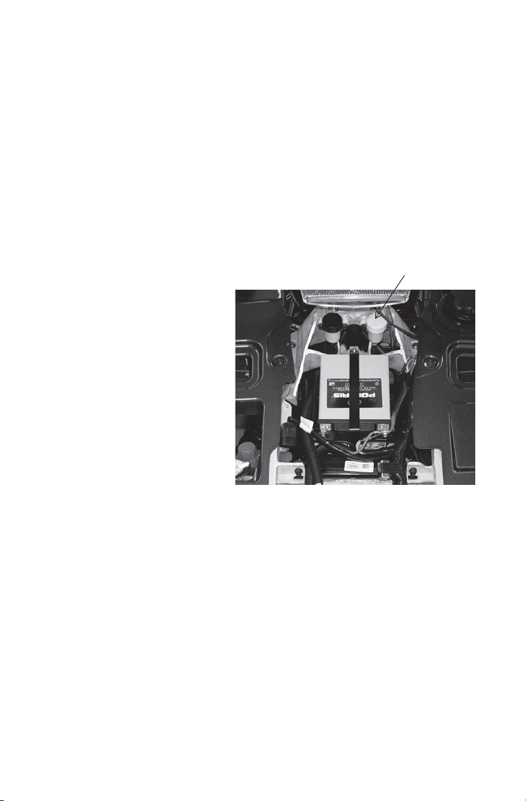
MAINTENANCE
ADC Fluid
Reservoir
Active Descent Control (ADC) Fluid
Check and change the ADC fluid level at the intervals outlined in the
Periodic Maintenance Chart beginning on page 85.
We recommend the use of POLARIS Demand Drive Plus Fluid for the
ADC unit. Maintain the fluid level between the minimum and maximum
marks on the reservoir. See page 137 for the part numbers of POLARIS
products.
NOTICE: Do not use brake fluid. Brake fluid will damage rubber components in
Fluid Check
1. Remove the front rack.
2. View the fluid level in the
3. If the level is below the
4. Reinstall the cap.
5. Reinstall the front rack.
the hydraulic system.
reservoir.
minimum mark, remove
the cap and add the
recommended fluid.
94
Page 97

MAINTENANCE
Bleeder
Screw
Cap
Bleeder
Valve
Screw
Active Descent Control (ADC) Fluid
Fluid Change
1. Position the vehicle on a level
surface. Before performing the
fluid change, allow the vehicle
to sit for at least 30 minutes.
2. Thoroughly clean the areas
around and on the ADC
reservoir and bleeder valves
(one on each side of the
differential).
3. Remove the reservoir cap and
diaphragm assembly. Use a
shop towel or suction tool to
remove debris from the fluid
and reservoir. Debris in the
reservoir may result in
inadequate bleeding and
reduced performance of the
system.
4. Fill the reservoir to the maximum line with fresh fluid.
5. Remove the protective caps from the bleeder valves.
6. Slowly loosen one of the bleeder valve screws (turn counter-clock-
wise) and allow fluid and trapped air to flow from the fitting.
Tighten the screw when clean fluid begins to flow. Repeat this step
for the remaining valve.
IMPORTANT: Close the bleeder va lve screws before the reservoir fluid level
drops below the minimum fill line. Adding fluid to an empty reservoir will result in
trapped air. If the level drops below the minimum line, add fluid to the maximum
line and repeat step 6 before proceeding.
7. Torque the bleeder valve screws to 80 in. lbs. (9 Nm). Reinstall the
8. Add fresh ADC fluid to the reservoir until the level is between the
9. Reinstall the cap securely. Clean up any drips or spills.
bleeder valve caps.
minimum and maximum marks. Make sure the reservoir is free of
debris.
95
Page 98

MAINTENANCE
Drain Plug
Fill Plug
Fill
Level
Rear Gearcase Oil
See the table on page 88 for fluid recommendations, capacities and plug
torques. Always check and change the rear gearcase oil at the intervals
outlined in the Periodic Maintenance Chart beginning on page 85. See
page 137 for the part numbers of POLARIS products.
The fill plug is located on the
rear of the gearcase. The drain
plug is located on the bottom
of the gearcase.
Maintain the fluid level at the
bottom of the fill hole threads.
Do not overfill.
Oil Check
1. Position the vehicle on a
level surface.
2. Remove the fill plug.
Check the oil level.
3. Add the recommended oil
as needed to bring the
level to the bottom of the
fill hole threads. Do not overfill.
4. Reinstall the fill plug. Torque to specification.
96
Page 99

MAINTENANCE
Rear Gearcase Oil
Oil Change
1. Position the vehicle on a level surface.
2. Place a drain pan under the drain hole.
3. Remove the drain plug. Allow the oil to drain completely.
4. Clean and reinstall the drain plug with a new sealing washer. Torque
to specification.
5. Remove the fill plug. Add the proper amount of the recommended
oil. Do not overfill.
6. Reinstall the fill plug. Torque to specification.
7. Check for leaks.
8. Dispose of used oil properly.
97
Page 100

MAINTENANCE
Power Steering Unit
If your model is equipped with
power steering, frequently
clean the areas around and on
the power steering unit to
allow proper cooling. Clean
these areas thoroughly.
Steering Assembly
The steering assembly of the ATV should be checked periodically for
loose nuts and bolts. If loose nuts and bolts are found, see your
POLARIS dealer for service before operating the vehicle.
Cooling System
The engine coolant level is controlled by the recovery system. Recovery
system components are the recovery bottle, the radiator filler neck, the
radiator pressure cap and the connecting hose.
As coolant operating temperature increases, the expanding (heated)
excess coolant is forced out of the engine, past the pressure cap, and into
the recovery bottle. As engine coolant temperature decreases the contracting (cooled) coolant is drawn back up from the bottle, past the pressure cap, and into the radiator.
Some coolant level drop on new vehicles is normal as the system is
purging itself of trapped air. Check the coolant level and maintain as
recommended by adding coolant to the recovery bottle.
POLARIS recommends the use of POLARIS Antifreeze 60/40 premix
or a 50/50 mixture of high quality aluminum compatible anti-freeze/
coolant and distilled water. POLARIS Antifreeze is already premixed
and ready to use. Do not dilute with water. See page 137 for the part
numbers of POLARIS products.
Always follow the manufacturer's mixing recommendations for the
freeze protection required in your area.
Clean
Often
98
 Loading...