

Page 1

DJ MIXER
DJM-3000
Operating Instructions
1
<DRB1314>
Page 2
Thank you for buying this Pioneer product.
Please read through these operating instructions so you will
know how to operate your model properly. After you have
finished reading the instructions, put them away in a safe place
for future reference.
In some countries or regions, the shape of the power plug and
power outlet may sometimes differ from that shown in the
explanatory drawings. However the method of connecting and
operating the unit is the same. K015 En
2
<DRB1314>
Page 3

IMPORTANT NOTICE
The serial number for this equipment is located on the rear
panel. Please write this serial number on your enclosed
warranty card and keep it in a secure area. This is for your
security.
<DRB1314>
3
Page 4

FEATURES
Effect Mixing
Changing between three kinds of effect mix (ECHO, ZIP,
ROLL) can be performed easily merely by operating the
Cross fader lever, or by pressing the Effect select/start
switch.
3-Band Equalizer and Kill
This 3-band equalizer corresponds to the HI, MID, and LOW
channels. The attenuation level also serves as a kill function,
which can decrease the level to –26 dB.
Variety of Effects
BPM Counter
The auto BPM counter provided makes music tempo visible
to the eye.
Both internal and external effects can be applied to all
channels, the microphone, and master.
A variety of effects can be enjoyed, including delay, echo,
auto pan, auto trans, filter, flanger, reverb and pitch shifter.
Peak Level Meter
The peak level meter provided is equipped with 11-bit LED
indicators for all channels.
Fader Start/Stop
The CD player can be started or stopped simply by increasing
or decreasing the level of the cross fader or channel fader.
(This function can only be used when the Pioneer CD player
series CMX-3000, CMX-5000, CDJ-1000, CDJ-100S, CDJ700S or CDJ-500
II is connected.)
Full range of input and output functions
This DJ Mixer is equipped with 4 (+3*) LINE inputs, 4
PHONO (dedicated MM) inputs, and 2 (+1*) MIC inputs, for a
total of 10 inputs. In addition to 2 master output lines (one
supporting professional-grade XLR mode), a variety of other
independent outputs are also provided, including booth
monitor output, recording output, and two digital outputs.
SEND/RETURN jacks are also provided for the connection of
external effects units.
* These additional connectors can optionally be switched
from PHONO input to make up the total.
CHECKING ACCESSORIES CONTENTS
÷ 2 short-circuit pin plugs
These are inserted in the PHONO 4 terminals.
÷ Operating instructions
÷ Warranty
FEATURES ................................................................. 4
CHECKING ACCESSORIES ....................................... 4
CAUTIONS REGARDING HANDLING ...................... 5
Location ........................................................................... 5
Installing the DJM-3000 in an EIA rack .......................... 5
Condensation .................................................................. 5
Cleaning the Unit ............................................................ 5
CONNECTIONS ......................................................... 6
PART NAMES AND FUNCTIONS ............................. 8
USING THE EFFECT FUNCTIONS .......................... 12
Features of Various Effectors ....................................... 12
Delay, Echo, Auto Pan, Auto Trans, Filter,
and Flanger Operations ................................................. 14
Operating Reverb and Pitch Shifter .............................. 16
Using an External Effector ............................................ 17
BPM COUNTING ..................................................... 18
Using the Auto Mode to Count BPM ........................... 18
Using the Manual Mode to Count BPM ....................... 19
USING THE FADER START FUNCTION ................ 20
Starting with the Channel Fader ................................... 21
Starting with the Cross Fader ....................................... 21
USING THE EFFECT MIX FUNCTION .................... 22
Effect Mix Features ...................................................... 22
Selecting the Effect Mix Function ................................ 23
Effect Mix Fader Mode ................................................. 24
Effect Mix Auto Mode .................................................. 25
TROUBLESHOOTING .............................................. 26
SPECIFICATIONS .................................................... 27
4
<DRB1314>
Page 5

CAUTIONS REGARDING HANDLING
Location
Install the unit in a well-ventilated location where it will
not be exposed to high temperatures or humidity.
÷ Do not install the unit in a location which is exposed to
direct rays of the sun, or near stoves or radiators.
Excessive heat can adversely affect the cabinet and
internal components. Installation of the unit in a damp or
dusty environment may also result in a malfunction or
accident. (Avoid installation near cookers etc., where the
unit may be exposed to oily smoke, steam or heat.)
÷ When the unit is used inside a carrying case or DJ booth,
separate it from the walls or other equipment to improve
heat radiation.
Installing the DJM-3000 in an EIA rack
The screw holes on the front panel of the DJM-3000 are
designed for use in attaching the unit to a 19-inch EIA rack.
÷ Attach the unit to the rack using screws of the appropriate
size (screws not provided with the unit).
Note
÷ Never place this unit directly above a power amplifier, as
the heat given off by the amplifier might result in damage
to the unit. Placing the unit directly above a power amplifier
might also result in ham radio signals being picked up or in
other types of interference.
÷ Always be sure to remove the unit from its rack before
shipping.
÷ When moving the unit while still installed in its rack,
exercise caution to avoid subjecting the unit to shocks or
vibration.
Condensation
When this unit is brought into a warm room from previously
cold surroundings or when the room temperature rises
sharply, condensation may form inside, and the unit may not
be able to attain its full performance. In cases like this, allow
the unit to stand for about an hour or raise the room
temperature gradually.
Cleaning the Unit
÷ Use a polishing cloth to wipe off dust and dirt.
÷ When the surfaces are very dirty, wipe with a soft cloth
dipped in some neutral cleanser diluted five or six times
with water and wrung out well, then wipe again with a dry
cloth. Do not use furniture wax or cleaners.
÷ Never use thinners, benzene, insecticide sprays or other
chemicals on or near this unit, since these will corrode the
surfaces.
<DRB1314>
5
Page 6

CONNECTIONS
When connecting or changing the connection of units, make sure to first turn off the power switch and disconnect the power cord
from the outlet.
1. Connection of Input Equipment
[A]
CDJ-1000 /
CDJ-100S /
CDJ-700S /
CDJ-500II
SEND
RL
(MONO)
SEND
DIGITAL OUT
RL
RLR
RETURN
L
REC OUT
(MONO)
LR12
CDJ-1000 /
CDJ-100S /
CDJ-700S /
CDJ-500II
MASTER OUT 2
R
RETURN
MASTER OUT 2
DJM-3000
[B]
3 COLD
1 GND
2 HOT
L
BOOTHMASTER
OUT 1 MONITOR
L
R
BOOTHMASTER
OUT 1 MONITOR
TALK OVER
LEVEL
MASTER
LEVEL
ATT.
R L
PHONO 4
R L
CMX-3000 / CMX-5000
CH - 4
LINE 7PHONO 4
L
R
LINE 7
CH - 4
LINEPHONO
R L
CH - 3
PHONO 3
/ LINE 6
PHONO 3
/ LINE 6
R L
[A] [B]
R L
CH - 2
SIGNAL
GND
PHONO 2
/ LINE 4
LINE 3
L
LINEPHONO
R
PHONO 2
LINE 3
CH - 2
LINE 5
L
R
LINE 5
CH - 3
R L
R L
CH-1
PHONO 1
LINE 1
/ LINE 2
L
LINEPHONO
R
PHONO 1
CONTROLCONTROLCONTROLCONTROL LINE 1
/ LINE 2/ LINE 4
MIC 2MIC 3CH-4CH - 1
R L
Connect to a wall’s
electrical outlet
(PHONO 4 cannot be used
when using MIC 3)
Player 3 Player 2 Player 1
When connecting an analog player to the CH-4 PHONO 4
connectors, first remove the short-circuit pin plugs (2) from
the jacks.
The short-circuit pin plugs are provided to reduce any residual
noise when an analog player is not connected to the PHONO
4 jacks, thus producing the highest possible sound quality.
After removing the pin plugs, store them securely, and
replace them in their original jacks any time an analog player
is not physically connected.
*1 Connect the cord for the analog player’s ground.
This terminal is exclusively for an analog player and is not
a safety earth.
*2 If you are using the unit with the separately sold CMX-
3000, CMX-5000, CDJ-1000, CDJ-100S, CDJ-700S, or
CDJ-500
II connected to the LINE terminals, the fader
start function can be used if the unit and CD player are
connected with a control cord.
*3 Because the unit’s PHONO input terminals are
exclusively for MM, use MM-type cartridges for the
analog player connected.
Cassette deck, etc.
*4 When connecting a cassette deck, set the PHONO/LINE
switch to the LINE position.
*5 When connecting an analog record player, set the
PHONO/LINE switch to the PHONO position.
Connecting audio cords
Use the cords with the red and white pin plugs.
Connect the white plug to ”L“ and the red plug to ”R“. Make
sure to insert the plugs completely.
White plug
L
Red plug
R
6
<DRB1314>
Page 7

2. Connection of Outputs, Microphones, etc.
CONNECTIONS
Microphone 1
External effector
DJM-3000
Power amplifier
(Supports XLR input)
Power amplifier
(Supports RCA input)
Power amplifier
(For booth monitor)
Headphones
Microphone 2
DJM-3000
3 COLD
1 GND
SEND
RL
(MONO)
DIGITAL OUT
RLR
SEND
RETURN
RL
(MONO)
L
LR12
REC OUT
R L
2 HOT
MASTER OUT 2
L
R
RETURN
MASTER OUT 2
XLR terminal polarity is as
BOOTHMASTER
OUT 1 MONITOR
L
R
BOOTHMASTER
OUT 1 MONITOR
TALK OVER
MASTER
shown in the diagram below.
2
3
1
CD recorder, etc.
Cassette deck, etc.
*6 MASTER LEVEL ATT.
(Master output-level attenuator shaft)
This shaft is used to decrease the output level to protect
connected amplifiers and speakers from excessive input.
(Attenuation: –∞ to 0 dB)
*7 Connect if you want to use another device for adjusting
sound quality.
SEND (output):
Connect this to the external effector’s input terminal.
When using a monaural input effector, connect it to the L
channel output. The effector will receive LR-mixed sound.
RETURN (input):
Connect this to the external effector’s output terminal.
When using a monaural output effector, connect it to the
L channel output. The signals from the effector will be
input to both the L and R channels.
RLR L
LEVEL
LEVEL
ATT.
HOT (+)
COLD (–)
GND
SIGNAL
CH - 2
PHONO 2
LINE 3
/ LINE 4
L
LINEPHONO
R
GND
LINEPHONO
CH - 4
CH - 3
LINE 7PHONO 4
L
R
PHONO 3
LINE 5
/ LINE 6
L
LINEPHONO
R
PHONO 3PHONO 4
/ LINE 6
MIC 3
(CH-4 PHONO 4 cannot
be used when
microphone is connected
to MIC 3.)
*8 REC OUT
Outputs sound to the same output source as the master
output, without being influenced by the master volume,
master balance and MONO/STEREO switches.
*9 TALK OVER LEVEL attenuation control
Attenuates sound level from sources other than MIC 1
and 2 when the MIC switch is set to the TALK OVER
position (range: –4 to –20 dB).
*10
MIC 1
Supports microphones with either XLR or PHONE type
jacks.
*11
DIGITAL OUT
Outputs same source as the master output.
The output level is not affected by MASTER LEVEL ATT.
(*6).
CH - 1
PHONO 1
/ LINE 2
PHONO 1PHONO 2
/ LINE 2/ LINE 4
LINE 1
L
R
CONTROLCONTROLCONTROLCONTROL LINE 1LINE 3LINE 5LINE 7
MIC 2MIC 3CH-4CH - 1CH - 2CH - 3CH- 4
<DRB1314>
7
Page 8

PART NAMES AND FUNCTIONS
Control Panel
¥ø π[
7
9
0
-
~
!
1
2
3
4
5
6
7
8
_+ ™¡ £¢
7
88
9
0
-
~
!
¥ MIC (Microphone Controls)
1 MIC 1 input jack
Use to connect a microphone with either XLR or PHONE
type jack.
2 TREBLE control
Adjusts high-range frequencies on microphone 1 and 2.
Center click position is provided for flat response.
Rotate the knob clockwise to augment treble response
(to +12dB), and rotate counterclockwise to diminish
treble response (to –12 dB).
3 BASS control
Adjusts low-range frequencies on microphone 1 and 2.
Center click position is provided for flat response.
Rotate the knob clockwise to augment bass response (to
+12dB), and rotate counterclockwise to diminish base
response (to –12 dB).
4 MIC 1 LEVEL
Controls sound volume on microphone 1 (attenuation:
–∞ to 0 dB)
5 MIC 2 LEVEL
Controls sound volume on microphone 2 (attenuation:
–∞ to 0 dB)
6 MIC switch
Use to select microphone input.
OFF: Disables microphone 1 and 2
ON: Enables microphone 1 and 2
TALK OVER: Enables microphone 1 and 2 while
attenuating other sound levels. The amount of
attenuation can be controlled by setting the rear-panel
TALK OVER LEVEL, within the range –4 dB to –20 dB.
~
!
9
0
-
8
====
7
#
$
@
^
9
0
-
~
! %
\‘
ø CH-1 to CH-4 (Channel Input Controls)
7 Input selector switches
Use to select an input source from among the components connected to the various channels.
CH-1: Switches between LINE 1 and PHONO 1/LINE 2
CH-2: Switches between LINE 3 and PHONO 2/LINE 4
CH-3: Switches between LINE 5 and PHONO 3/LINE 6
CH-4: Switches between LINE 7 and MIC 3/PHONO 4
¶ On CH-1 to CH-3, the rear panel PHONO/LINE switches
are used to switch between PHONO 1, 2, 3 and LINE 2,
4, and 6.
¶ On CH-4, switching between MIC 3 and PHONO 4 is
based on the presence/absence of a plug in the MIC 3
connector (when a plug is inserted, MIC 3 is selected).
8 TRIM control
Use to control the input signal level.
Rotate clockwise to increase the level (to +9 dB); rotate
counterclockwise to decrease the level (to –∞)
9 HI control (high-range equalizer)
Use to adjust high-range frequency of input.
When the dial is set to the center click setting, flat
response is provided.
Rotate clockwise to increase response (to +12 dB), and
rotate counterclockwise to decrease response (to –26
dB).
0 MID control (mid-range equalizer)
Use to adjust mid-range frequency of input.
When the dial is set to the center click setting, flat
response is provided.
Rotate clockwise to increase response (to +12 dB), and
rotate counterclockwise to decrease response (to –26
dB).
“
&
]
*
(
)
8
<DRB1314>
Page 9

PART NAMES AND FUNCTIONS
- LOW control (low-range equalizer)
Use to adjust low-range frequency of input.
When the dial is set to the center click setting, flat
response is provided.
Rotate clockwise to increase response (to +12 dB), and
rotate counterclockwise to decrease response (to –26
dB).
= H.P CUE (Headphones cue switch)
When this switch is pressed it lights orange and the
corresponding channel is output to headphones. When
the switch is pressed again the light goes out and the
channel’s output to the headphones is cut.
When the beat effector function is set to AUTO BPM, this
switch functions to select the BPM display channel.
~ Peak level meter
Peak levels are displayed as they occur and maintained
for 2 seconds.
The meter displays the channel fader output level.
Displayable range is from –22 dB to +14 dB.
! Channel fader lever
Use to adjust the sound level at each channel.
π MASTER (Master Controls)
@ MONO/STEREO selector switch
Use to select whether the master output and booth
monitor output are monaural or stereo.
# MASTER LEVEL meter
Displays output level following adjustment of the
MASTER fader lever, and holds the display for 2 seconds.
Displayable range is from –22 dB to +14 dB.
$ H.P CUE (Headphones cue switch)
When this switch is pressed it lights orange and the
master output is heard in the headphones. When the
switch is pressed again the light goes out and the master
output to the headphones is cut.
% MASTER fader lever
Use to control the master output level.
The rear panel MASTER LEVEL ATT. control can also be
used to reduce the output level.
^ MASTER BALANCE control
Use to adjust the balance of right-left channels for master
output and booth monitor output.
[ BOOTH MONITOR Control
Use to adjust the output at the BOOTH MONITOR
connectors on the rear panel. Not affected by the
MASTER fader lever (%).
“ POWER Switch
* MIXING control
Use to adjust the headphones monitor sound.
When rotated fully clockwise, the master output sound
only is heard (only when MASTER H.P CUE switch is set
to ON). When rotated fully counterclockwise, only the
channel selected with the H.P CUE switch (other than
MASTER) is heard.
At the center click position, the master output and source
selected with the H.P CUE switch are at equal levels.
( LEVEL control
Use to control the headphones monitor level. When one
of CH-1 to CH-4 is selected, this control is not affected by
the MASTER fader lever (%) and the MASTER BALANCE
control (^).
) PHONES (headphones jack)
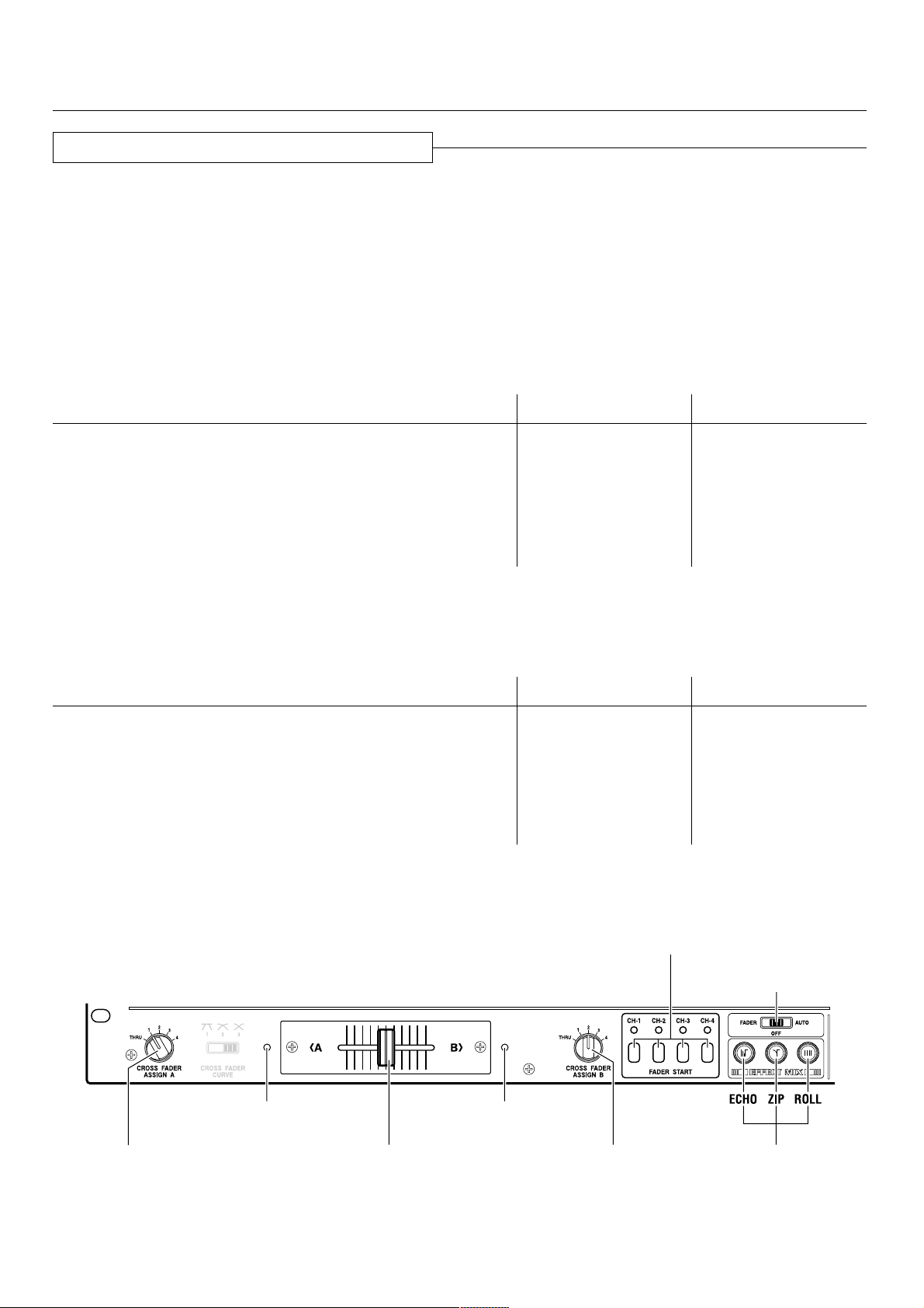
‘ Cross Fader Controls
_ CROSS FADER ASSIGN A switch
When using the cross fader with two sources (A, B), this
switch selects the source assigned to A.
THRU: When cross fader is not used, sets to THRU.
1-4: Use to select the channel (CH-1 to CH-4) assigned
to A.
Channels other than those assigned to A and B
can be output without passing through the cross
fader.
+ CROSS FADER CURVE selector switch
Use to select one of three rising curve patterns for the
cross fader function.
¡ Fader display A
During the effect mix mode, displays the output of
sounds from the channel selected with the CROSS
FADER ASSIGN A switch.
™ Cross fader lever
Use to adjust the mix of sounds from the sources
assigned to A and B by the ASSIGN switches (_) and (¢).
£ Fader display B
During the effect mix mode, displays the output of
sounds from the channel selected with the CROSS
FADER ASSIGN B switch.
¢ CROSS FADER ASSIGN B switch
When using the cross fader with two sources (A, B), this
switch selects the source assigned to B.
THRU: When cross fader is not used, sets to THRU.
1-4: Use to select the channel (CH-1 to CH-4) assigned
to B.
Channels other than those assigned to A and B
can be output without passing through the cross
fader.
] HEADPHONES Controls
& MONO SPLIT/STEREO selector switch
Use to select whether to split monitor sound on the left
and right of the headphones or to keep sound in stereo
form.
When set to MONO SPLIT, the headphones output is set
to 2-channel monaural; the Left channel becomes the
source selected with the H.P CUE switch, while the Right
channel becomes the master output sound (only when
MASTER H.P CUE switch is set to ON).
\ FADER START Switches
CH-1, CH-2, CH-3, CH-4
When a CD player (CMX-3000, CMX-5000, CDJ-1000,
CDJ-100S, CDJ-700S or CDJ-500II) is connected to one of
the above channels of this unit via a control cord, the CD
player’s CUE START/STOP operation will start when the
channel fader is moved from “0” upwards, and will stop
(back cue) when the channel fader is returned to “0”. The
indicator of the selected channel will light orange during
this operation. Also, if a channel is assigned to the cross
fader, the cross fader is given priority; when the Cross
fader lever begins moving from the A side toward B side,
the CD player assigned to the B side will start, and when
the lever reaches the B side, the A side source will stop
(back cue).
<DRB1314>
9
Page 10
PART NAMES AND FUNCTIONS
∞
§
¶
•
ª
º
–
≠
Ÿ
«
⁄
¤
‹
›
fi
Å
fl‡ ·°
« BEAT EFFECTS Controls
∞ 1-4 (Channel displays)
Displays the channel selected for BPM count.
§ AUTO BPM COUNTER
When AUTO BPM is selected with the Effect selector
switch (⁄), displays the BPM of the channel (CH-1 to CH-
4) selected with the H.P CUE switch (=). The indicator
flashes during counting, or if it is unable to count BPM.
¶ BPM counter range selector switch
¶ BPM can be selected in one of the ranges 70-139, 91-
180, 70-180 or manual mode. Set the range best
matching the track you are measuring.
• BPM counter range displays
¶ Displays the BPM count range selected. When BPM
count range 70-180 is selected, both indicators 70-139
BPM and 91-180 BPM light.
¶ If both indicators are out, it indicates manual mode.
For more information about manual mode, see the item
“BPM COUNTING” “on pages 18-19.
If the Effect selector switch (⁄) is set to DELAY, ECHO,
PAN, TRANS, FILTER or FLANGER, the indicator will
display the BPM of the source selected with the Effect
CH. SELECT switch (¤).
ª 1-4, MIC, MASTER (Source displays)
Displays the source selected with the Effect CH. SELECT
switch (¤).
¶ If the Effect CH. SELECT switch is used to select
“CF.A” or “CF.B”, the channel that lights will be the
one (1-4) selected with the respective ASSIGN switch
(_), (¢).
º PARAMETER 1 (Parameter 1 / BPM counter)
The display contents change in accordance with the
setting of the Effect selector switch (⁄).
¶ When AUTO BPM is selected, the display shows the
BPM of the source selected with the Effect CH.
SELECT switch (¤). The indicator flashes during BPM
counting, or when it is unable to count BPM.
¶ When SND/RTN is selected, nothing is displayed.
¶ When a setting other than AUTO BPM or SND/RTN is
selected, the display shows the value of the effect set
with Effect PARAMETER 1 control (‹).
– BEAT (Effect synchronous displays / Beat displays)
This display’s contents differ depending on the setting of
the Effect selector switch (⁄).
¶ When DELAY, ECHO, PAN, or TRANS are selected, the
display shows the equivalent parameter 1 value for the
BPM of the selected source. The display lights when
the beat is in the range 1/2 to 4/1. If the beat value is
below 1/2, pressing the Effect beat selector switch (@)
causes the value to become 1/4, and all display
indicators go out. If the beat value is above 4/1,
pressing the Effect beat selector switch (#) causes the
value to become 8/1, and all display indicators go out.
If the value does not match the number of beats, the
indicator for the nearest beat value will flash.
¶ When FILTER or FLANGER are selected, the display
shows the equivalent parameter 1 value for the BPM of
the selected source. The display lights when the beat is
in the range 1 to 16. If the beat value is below 1,
pressing the Effect beat selector switch (@) causes the
value to become 1/2, and all display indicators go out. If
the value is above 16, pressing the Effect beat selector
switch (#) causes the value to become 32, and all
display indicators go out.
If the value does not match the number of beats, the
indicator for the nearest beat value will flash.
¶ When REVERB is selected, the display shows the
amount of reverberation applied.
¶ When PITCH is selected, the display shows the amount
of pitch modification applied.
¶ No display appears when AUTO BPM or SND/RTN are
selected.
10
<DRB1314>
Page 11

PART NAMES AND FUNCTIONS
≠ Effect beat selector switches (@, #)
Use this switch to change the value of Effect
PARAMETER 1 control (‹) in accordance with the BPM
of the source selected with the Effect CH. SELECT
switch (¤). The setting value of this switch differs
depending on the setting of the Effect selector switch
(⁄).
¶ When DELAY, ECHO, PAN, or TRANS are selected, the
parameter 1 value for the BPM of the selected source
can be set to 1/4 beat, 1/2 beat, 1/1 beat, 2/1 beat, 4/1
beat, or 8/1 beat.
¶ When DELAY or ECHO are selected, values can be set
to 1/4x, 1/2x, 1/1x, 2/1x, 4/1x or 8/1x, within a range
such that the parameter 1 value does not exceed 3500
ms.
¶ When FILTER or FLANGER are selected, the parameter
1 value for the BPM of the selected source can be set
to 1/2 beat, 1 beat, 2 beats, 4 beats, 8 beats, 16 beats,
or 32 beats.
¶ When PITCH is selected, the value can be set to
–100%, –50%, –33%, 0%, 33%, 50%, or 100%.
¶ When REVERB is selected, the value can be set to
10%, 20%, 35%, 50%, 65%, 80%, or 90%.
¶ This control is disabled when AUTO BPM or SND/RTN
are selected.
Ÿ H.P CUE (Headphones cue switch)
When this switch is pressed it lights orange, and beat
effects are output to the headphones. Pressing the
switch again disconnects the beat effect to the
headphones and turns off the switch lamp.
⁄ Effect selector switch
Use to select desired effects (see page 12).
¤ CH. SELECT (Effect channel selector switch)
Use to select the source you wish to apply effects to.
‹ TIME (PARAMETER 1)
(Effect parameter 1 control)
This control is used to set the time parameter for the
onboard effector (see page 14).
› LEVEL/DEPTH (PARAMETER 2)
(Effect parameter 2 control)
This control is used to set quantitative parameters for the
onboard effector (see page 14).
fi ON/OFF, TAP (Effect ON/OFF switch, TAP switch)
This switch produces different operations depending on
the setting of the Effect selector switch (⁄)
¶ When DELAY, ECHO, PAN, TRANS, FILTER, FLANGER,
REVERB, PITCH, or SND/RTN are selected, the switch
operates to turn the selected effect ON/OFF.
OFF: the orange lamp lights; ON: orange lamp flashes.
¶ When AUTO BPM is selected the switch becomes a
“TAP” switch; by tapping the switch together with the
source beat, the BPM can be input manually.
When tapping the TAP switch to count the BPM, both
BPM counter range displays (70-139 BPM and 91-180
BPM) go out, and the manual mode is enabled (see
page 19).
Å EFFECT MIX Controls
fl FADER/OFF/AUTO (EFFECT MIX selector switch)
Use to select the cross fader effect mode.
FADER: Selects Effect Mix Fader mode. When this is
selected, the Cross fader lever (™) can be used
to control effects and perform cue start and back
cue.
OFF: Normal mode
AUTO: The Effect Mix Auto mode. When this is
selected, the Effect select/start switches (‡, °,
·) can be used to control effects, perform cue
start and back cue.
‡, °, · Effect select/start switches
Use to select the type of Effect Mix desired (default is
ECHO)
¶ The switch for the selected function flashes.
‡ ECHO switch
° ZIP switch
· ROLL switch
11
<DRB1314>
Page 12

USING THE EFFECT FUNCTIONS
With the built-in digital signal processor (DSP), sound effects can be enjoyed and BPM measured.
Features of Various Effectors
AUTO BPM COUNTER
Automatically measures music BPM (beats per minute; tempo) and displays it digitally.
It not only counts the beat of bass sounds but also calculates (using a computer) the music’s original BPM, which DJs require, and
displays it digitally.
Thus, BPM can now be checked not only aurally, as was conventional, but also visually, enabling quicker, simpler mixing of music
with different tempos.
Use of the TAP switch to input the beat manually makes it possible to set BPM for music for which it is difficult to measure (a
capella, improvisation, etc.).
Beat Effector (Effects linked to BPM)
Links various effects to the BPM calculated with the aforementioned AUTO BPM COUNTER to enable unprecedented sound
production.
1. DELAY (one sound repeated)
Quickly and easily mixes delayed sounds of 1/4, 1/2, 3/4,
1/1, 2/1, 4/1 and 8/1 beats.
Mixing with 1/2-beat-delayed sound, for example, will
change the beat from 4 to 8.
Mixing with a 3/4-beat-delayed sound will change the
rhythm to a bouncy one.
Example:
Original
(4 beats)
1/2 delay
(8 beats)
2. ECHO (repeated sounds)
Quickly and easily mixes echoes of 1/4, 1/2, 3/4, 1/1, 2/1,
4/1 and 8/1beats.
When input sound is cut with a 1/1-beat echo, for
example, the music will fade out while sounds are
repeated that match the beat.
When a 1/1-beat echo is imposed on the microphone,
microphone sound will be played repeatedly, matching
the beat.
Troll (musical round-type) effects can be produced by
imposing a 1/1-beat echo on song vocals.
3. Auto Pan [PAN (L-R BALANCE)]
Automatically pans sound to the left and right (auto beat
pan) to the rhythm of a 1/4, 1/2, 3/4, 1/1, 2/1, 4/1 or 8/1
beat.
Short auto pan, for panning sound to the left and right in a
short time that cannot be covered manually, is also
possible.
Example:
Auto Beat Pan
L
Center
(Stereo)
R
1 cycle = 1/4, 1/2, 3/4, 1/1, 2/1, 4/1 or 8/1 beat
L
Center
(Stereo)
R
Short Auto Pan
4. Auto Trans (TRANS)
Automatically cuts sound to the rhythm of a 1/4, 1/2, 3/4,
1/1, 2/1, 4/1 or 8/1 beat.
Example:
Cut Cut
Example:
1 beat 1 beat
Cuts the input sound
12
<DRB1314>
Beat
Time
1 cycle = 1/4, 1/2, 3/4, 1/1, 2/1, 4/1 or 8/1 beat
Fade out
Page 13

5. FILTER
Changes the tone greatly by shifting the filter’s
frequency in units of 1/2, 1, 2, 4, 8, 16, and 32 beats.
Example
Frequency
1 cycle = 1/2, 1, 2, 4, 8, 16 or 32 beat
6. FLANGER
Quickly and easily produces 1-cycle flanger effect for
beats of 1/2, 1, 2, 4, 8, 16, or 32.
Example
Short delay
USING THE EFFECT FUNCTIONS
1 cycle = 1/2, 1, 2, 4, 8, 16 or 32 beat
7. REVERB
Produces a reverberation effect.
8. PITCH (Pitch Shifter)
Shifts interval (pitch or key) within a range of ±1 octave.
As the speed of analog-record turntables and CD players
changes as a percent, interval changes can be corrected
on a percent basis.
Applying the pitch shifter to microphone sound produces
voice changer effects. Mixing with original sound
produces a choral effect.
9.
Send/Return (SND/RTN: External effect input/output)
Makes diverse effects possible through connection to
available effectors, samplers, etc.
13
<DRB1314>
Page 14
USING THE EFFECT FUNCTIONS
Delay, Echo, Auto Pan, Auto Trans, Filter, and Flanger Operations
Items Set for Each Effect
Effect
DELAY
ECHO
PAN
(Auto pan)
TRANS
(Auto trans)
FILTER
FLANGER
Effect Parameter 1 (TIME)
Delay time
Setting range: 1 to 3500mSec,
in 1msec steps
Delay time
Setting range: 1 to 3500mSec,
in 1msec steps
Pan time (changeover time)
Setting range: 10 to 16000mSec,
in 5mSec steps for 10 to 1000 and
10msec steps for 1000 to 16000
Trans time (changeover time)
Setting range: 10 to 16000mSec,
in 5mSec steps for 10 to 1000 and
10msec steps for 1000 to 16000
Filter time (cycle)
Setting range: 10 to 16000mSec,
in 5mSec steps for 10 to 1000 and
10msec steps for 1000 to 16000
Flanger time (cycle)
Setting range: 10 to 16000mSec,
in 5mSec steps for 10 to 1000 and
10msec steps for 1000 to 16000
Effect Parameter 2 (LEVEL/DEPTH)
Effect mix ratio
(Balance between original and delayed sound levels)
Effect mix ratio
(Balance between original and echo sound levels)
Effect mix ratio
(Balance between original and panned sound levels)
Effect mix ratio
(Balance between original and cut sound levels)
Resonance
(Filter resonance sound level)
Feedback
(Flanger feedback sound level)
Example: Applying the delay effect to music on CH-2.
BPM display
Effect parameter/BPM display
H.P CUE switch
Effect selector switch
Effect CH. SELECT switch
Effect PARAMETER 1 control
(TIME)
Effect PARAMETER 2 control
(LEVEL/DEPTH)
Effect ON/OFF switch
14
<DRB1314>
Page 15

USING THE EFFECT FUNCTIONS
1 Set the Effect selector switch to DELAY.
2 Set the Effect CH. SELECT switch to 2.
÷ The Effect parameter/BPM display LED “2” will light.
÷ The BPM of the music input to CH-2 will be displayed
on the AUTO BPM COUNTER.
* The BPM band that matches the music on CH-2 can be
selected with the BPM counter range selector switch.
* The counter will flash if BPM cannot be counted for
more than 2 seconds. In this case, use manual mode to
make settings (see page 19).
3 Set the parameter value.
When the H.P CUE switch (in the BEAT EFFECTS
controls) is pressed, the effect can be confirmed by
listening to the headphones output.
Setting the Delay Time
÷ Setting the delay time to match one beat of the BPM
displayed on the AUTO BPM COUNTER makes effect
application more effective.
÷ By pressing the Effect beat selector switch (@ or #),
delay time of 1/4 to 8/1 can be set for one beat of the
counted BPM.
÷ More precise delay times can be set with the Effect
PARAMETER 1 control (TIME).
÷ As “1/2” will light on the beat display if delay time is set
to 1/2 of one beat of the BPM, the parameter value can
be set using the beat display as a guide.
Setting to Balance Original and Delayed Sound Levels
÷ The balance between original and delayed sound levels
is set using the Effect PARAMETER 2 control (LEVEL/
DEPTH). Turning this control to the left will decrease
delayed sound and turning it to the right will increase it.
Precautions:
÷ If the channel has been changed with the Effect CH.
SELECT switch when delay, echo, reverb (pages 16 and
17) and similar effects have been turned on, all of the
reverberation of the prior channel’s effects will be output.
÷ Only operate the Effect selector switch when effects are
off (when the Effect ON/OFF switch is lit orange).
Operating it with effects on could generate noise.
÷ Display where a 1/2-beat delay (250mSec) has been set to
music with a BPM of 120 (time conversion: 500mSec).
BPM display
Counter
BPM counter range
selector switch
Effect parameter/
BPM display
“1/2” will light
LED
Counter
Beat display
Effect beat selector
switches
4 Turn on the Effect ON/OFF switch.
÷ The Effect ON/OFF switch will flash orange, and the
delay effect will be applied to master output.
÷ If the switch is pressed once more, the effect will be
turned off.
* If it is turned on in time to the beat, the effect’s cycle
will also start on the beat.
Echo, auto pan, auto trans, filter, flanger can also be set
similarly.
15
<DRB1314>
Page 16

USING THE EFFECT FUNCTIONS
Operating Reverb and Pitch Shifter
Effector Settings
Effect
REVERB
PITCH
(Pitch Shifter)
Example: Display when music on CH-3 has been pitch-shifted 90%.
Effect parameter/BPM display
Reverb time (echo time)
Setting range: 1 to 100%,
Pitch
Setting range: 0 to ±100%,
Effect Parameter 1 (TIME)
in 1% steps
in 1% steps
BPM display
Effect Parameter 2 (LEVEL/DEPTH)
Effect mix ratio
(Balance between original and reverb sound levels)
Effect mix ratio
(Balance between original and pitch-shifted sound
levels)
Effect selector switch
Effect CH. SELECT switch
Effect PARAMETER 1 control
(TIME)
H.P CUE switch
1 Set the Effect selector switch to PITCH.
2 Set the Effect CH. SELECT switch to 3.
÷ The Effect parameter/BPM display LED “3” will light.
* The entire BPM display will turn off.
3 Set the parameter value.
When the H.P CUE switch (in the BEAT EFFECTS
controls) is pressed, the effect can be confirmed by
listening to the headphones output.
Setting Pitch
÷ Pressing # on the Effect beat selector switch will
increase the pitch setting +33%, +50% or +100%,
while pressing @ will decrease it –33%, –50% or
–100%.
÷ More precise pitch can be set with the Effect
PARAMETER 1 control (TIME).
Effect PARAMETER 2 control
(LEVEL/DEPTH)
Effect ON/OFF switch
Setting the Balance Between Original and PitchShifted Sound Levels
÷ The balance between original and pitch-shifted sound
levels is set using the Effect PARAMETER 2 control
(LEVEL/DEPTH). Turning this control to the left will
decrease pitch-shifted sound and turning it to the right
will increase it.
16
<DRB1314>
Page 17

USING THE EFFECT FUNCTIONS
4 Turn the Effect ON/OFF switch on.
÷ The Effect ON/OFF switch will flash orange and the
effect (pitch shift) will be applied to master output.
÷ If the switch is pressed once more, the effect will turn
off.
Reverb can be set similarly.
Precautions:
÷ If the channel has been changed with the Effect CH.
SELECT switch when delay, echo (pages 14 and 15),
reverb and similar effects have been turned on, all of the
reverberation of the prior channel’s effects will be output.
÷ Only operate the Effect selector switch when effects are
off (when the Effect ON/OFF switch is lit orange).
Operating it with effects on could generate noise.
Using an External Effector
÷ Display when CH-3 has been pitch-shifted by 90%.
BPM display
Effect parameter/
BPM display
LED
Counter
Beat display
Effect beat selector
switches
The following example is for applying external effects to
music on CH-3.
1 Set the Effect selector switch to SND/RTN.
2 Set the Effect CH. SELECT switch to 3.
÷ The Effect parameter/BPM display LED “3” will light.
3 Set external effector parameters, etc.
÷ When the H.P CUE switch (in the BEAT EFFECTS
controls) is pressed, the effect can be confirmed by
listening to the headphones output.
4 Adjust the return level.
÷ The return level from the external effector can be
adjusted with the Effect PARAMETER 2 control
(LEVEL/DEPTH).
* Effect PARAMETER 1 control (TIME) will not function.
5 Turn on the Effect ON/OFF switch.
÷ The Effect ON/OFF switch will flash orange, and the
external effect will be applied to music on CH-3.
÷ Pressing the switch once more will turn the effect off.
÷ Display when an external effect has been applied to CH-3.
BPM display
Effect parameter/
BPM display
LED
17
<DRB1314>
Page 18

BPM COUNTING
Using the Auto Mode to Count BPM
This mode counts and displays the BPM of the channel selected with the H.P CUE switch and (when Effect selector switch is set
to AUTO BPM, the CH-1 to CH-4 H.P CUE switch becomes the AUTO BPM COUNTER’s channel select switch) the channel
selected with the Effect CH. SELECT switch, thus making it easy to synchronize two tracks with different speeds (count range
70.0-180.0 BPM).
Example: Display of BPM for CH-1 selected with H.P CUE switch and CH-2(2) selected with Effect CH. SELECT switch:
CH-1 H.P CUE switch
BPM display
Effect parameter/
BPM display
Effect selector switch
Effect CH.
SELECT switch
Effect
PARAMETER 1
control (TIME)
TAP switch
1 Set the Effect selector switch to AUTO BPM.
2 Press the BPM counter range selector switch to
choose the desired BPM count range.
÷ Select from one of the three ranges: 70-139, 91-180, or
70-180. The 70-180 range is selected with both LEDs
(70-139 BPM and 91-180 BPM) light.
3 Set the Effect CH. SELECT switch to 2.
÷ The Effect parameter/BPM display LED “2” will light.
÷ The BPM of the music input to CH-2 will appear on the
Effect parameter/BPM display’s counter.
* If the BPM cannot be counted for 2 seconds or more,
the counter will flash.
* Some tracks cannot be counted in AUTO BPM mode. In
this event, set to manual mode to count the BPM (see
page 19).
4 Press CH-1 H.P CUE switch.
÷ The BPM display LED “1” will light.
÷ The BPM of the music input to CH-1 will appear on the
AUTO BPM COUNTER.
* To measure BPM accurately, select only one channel
(CH-1 to CH-4 H.P CUE switch) for the AUTO BPM
COUNTER.
÷ Display when the BPM of CH-1 and CH-2 (126) match.
BPM display
Effect parameter/
BPM display
LED
Counter
BPM counter range
selector switch
LED
Counter
18
<DRB1314>
Page 19
Using the Manual Mode to Count BPM
BPM COUNTING
7 When BPM cannot be counted in AUTO BPM mode:
If auto BPM counting is not possible, use the TAP switch
for manual input.
÷ When the TAP switch is pressed in time to the music’s
beat, the light in the BPM counter range display will
turn off and manual mode will go into effect.
÷ The BPM value input with the TAP switch will be
displayed on the Effect parameter/BPM display’s
counter (lower side), and the BPM display’s counter
(upper side) will turn off.
÷ To return to AUTO BPM mode, press the BPM counter
range selector switch and set the counter range.
7 When BPM cannot be counted during delay, echo,
auto pan, auto trans, filter and flanger operations
(pages 14 and 15):
If BPM cannot be counted for more than 2 seconds during
effect operations, the BPM display’s counter (upper side)
will flash. In such a case, change the Effect selector
switch to AUTO BPM and use the TAP switch for manual
input.
÷ After the BPM value input via the TAP switch has been
displayed on the Effect parameter/BPM display’s
counter (lower side) and the Effect selector switch
restored to the original effect, the BPM value input will
be displayed on the BPM display’s counter (upper side).
BPM display
Effect parameter/
BPM display
Counter
BPM counter range
selector switch
BPM counter range
displays
Counter
If you already know the BPM for a track, you can set the
BPM input without using the “TAP” input.
÷ Change the Effect selector switch to AUTO BPM and
press the BPM counter range selector switch and both
BPM counter range displays (70-139 BPM and 91-180
BPM) will turn off.
÷ If the Effect PARAMETER 1 control (TIME) is turned,
the Effect parameter/BPM display’s counter (lower
side) will display the BPM, with adjustment possible
from the first digit.
Turning the PARAMETER 1 control while pressing the
TAP switch makes it possible to adjust the BPM from
the first decimal place.
When the BPM value has been set and the Effect
selector switch restored to the original effect, the BPM
value set will be displayed on the BPM display’s
counter (upper side).
19
<DRB1314>
Page 20

USING THE FADER START FUNCTION
If the separately sold CMX-3000, CMX-5000, CDJ-1000, CDJ-100S, CDJ-700S and CDJ-500 II players are connected to CH-1 – CH4, they can be started using the Channel fader lever or Cross fader lever, as long as the control cords have been connected.
Channel fader
lever
FADER START
switches
CROSS FADER CURVE
selector switch
CROSS FADER
ASSIGN A switch
Fader Start Play (To Use Fade-in Operation with a Connected CD Player)
Fader start play will be possible when the unit has been
connected with control cords to the CMX-3000, CMX5000, CDJ-1000, CDJ-100S, CDJ-700S, and CDJ-500
players for DJs. In other words, when the DJ mixer’s
channel fader or cross fader volume is turned up, the CD
player’s pause function will be released, and the music will
start automatically and instantly. In addition, because the
CD player can be restored to the cue point when the fader
is returned to its original position, sampler-type play is also
possible.
Cross Fader Start Play and Back Cue Play
When “A” is at the cue point during standby, it can be
started simply by moving the Cross fader lever from the
right (B) side to the left (A) side. “B” will back cue (return
to the cue point) at the same time.
Moreover, when “B” is at the cue point during standby,
it can be started simply by moving the Cross fader lever
from the left (A) side to the right (B) side. (“A” will back
cue at the same time.)
Cross fader lever
CMX-3000
II CD
CROSS FADER
ASSIGN B switch
A
Control cords
B
DJM-3000
CD players for which fader start play is possible when
connected to this unit
CMX-3000
CMX-5000
CDJ-1000
CDJ-100S
CDJ-700S
CDJ-500
II
20
<DRB1314>
Cross fader lever
Channel fader lever
Page 21

Starting with the Channel Fader
USING THE FADER START FUNCTION
1 Turn on the FADER START switch (CH-1, CH-2,
CH-3 or CH-4) of the channel connected to the
CD player to be controlled.
The indicator for the selected channel will light.
2 Push the Channel fader lever all the way to the
bottom.
3 Set a cue point on the CD player, and set the unit
to standby (pause) at the cue point.
4 When you want to start the player, push up the
Channel fader lever and the CD player will begin
playing.
Precaution:
÷ Channels selected with the CROSS FADER ASSIGN A
and B switches cannot be started with the channel
fader.
Starting with the Cross Fader
1 Turn on the FADER START switch (CH-1, CH-2,
CH-3 or CH-4) of the channel connected to the
CD player to be controlled.
The indicator for the selected channel will light.
2 Using the CROSS FADER ASSIGN A and B
switches, select the channel (CH-1, CH-2, CH-3 or
CH-4) that the CD player is connected to.
The following is an example of starting a CD player
connected to CH-1.
Example:
If cue points have been set in advance when using the
CMX-3000, CMX-5000, CDJ-1000, CDJ-100S, CDJ-700S
and CDJ-500 II, it is not necessary to leave the CD player
on standby at the cue point.
If the Channel fader lever is returned to its original
position after playing has started, the CD player will
return to the cue point and be on standby.
FADER START
switch
Channel fader lever
5 Use the CROSS FADER CURVE selector switch
to select the cross fader startup curve.
6 When the Cross fader lever is slid in the opposite
direction as in “3”, the CD player will begin
playing.
3 Slide the Cross fader lever all the way in
direction opposite the source you want to start.
In the following example, startup is done with the CD
player connected to CH-1 set to ASSIGN A.
Example:
ASSIGN A switch Cross fader lever
4 Set a cue point on the CD player, and set the unit
to standby (pause) at the cue point.
ASSIGN A switch Cross fader lever
If cue points have been set in advance when using the
CMX-3000, CMX-5000, CDJ-1000, CDJ-100S, CDJ-700S
and CDJ-500 II, it is not necessary to leave the CD player
on standby at the cue point.
If the Cross fader lever is returned to its original position
after playing has started, the CD player will return to the
cue point and be on standby.
21
<DRB1314>
Page 22

USING THE EFFECT MIX FUNCTION
When this mixer is combined with separately purchased CD players (CMX-3000, CMX-5000, CDJ-1000, CDJ-100S, CDJ-700S or
CDJ-500II), the Cross fader lever can be operated to produced automatic linked fade-in and fade-out sound from Player A to Player
B. If desired, the effect mode can be employed for simultaneous linked operation (requires connection of control cord). These
operations can be performed by means of a single button.
Effect Mix Features
Effect Mix Fader Mode
7 ECHO
The sound volume of the effect changes depending on the
position of the Cross fader lever.
Depending on the setting of the Effect PARAMETER control,
the ECHO repeat can be changed from 1/2, to 3/4, 1/1, 2/1 or
4/1 beats. When the lever reaches the other side, the channel
assigned to the other side is connected.
Example: Cross fader lever position and effect volume
setting when effect is set for side A
Side A Side B
Normal playback
side A
100%
50%
0%
Effect amount
7 ZIP
The pitch of the effect changes depending on the position of
the Cross fader lever.
When the lever reaches the other side, the channel assigned
to the other side is connected.
Example: Cross fader lever position and pitch setting
when effect is set for side A
Side A Side B
Normal playback
side A
0%
–100%
–200%
Effect pitch
7 ROLL
The traverse of the Cross fader lever is divided into four
quarters, and as the lever is moved from the effect side, the
effect is set to 1/1, 1/2, 1/4, and 1/8 beats.
The beat pitch of the effect changes through the range 1/1 to
1/8 depending on the position of the Cross fader lever. When
the lever reaches the other side, the channel assigned to the
other side is connected.
Example: Cross fader lever position and beat setting
when effect is set for side A
Side A Side B
Normal
playback
side A
1/1 1/2 1/4 1/8
beat beat beat beat
Normal playback
side B
Normal playback
side B
Normal
playback
side B
Effect Mix Auto Mode
7 ECHO
The volume of the effect fades at the effect time set in
accordance with the setting of the Effect PARAMETER
control, and leads into the next track.
Example: When set for 4-beats
Previous track Next track
During effect
Volume fades
1 beat
7 ZIP
The pitch of the effect fades at the effect time set in
accordance with the setting of the Effect PARAMETER
control, and leads into the next track.
Example: When set for 4-beats
Previous track Next track
7 ROLL
The ROLL pattern changes in accordance with the setting of
the Effect PARAMETER control.
When set for 1 beat or 2 beats, outputs a repeated 1/4 beat
sound.
When set for 4 beats or 8 beats, the effect time is divided
into two, and repeated 1/2 and 1/4 beats are output.
When set for 16 beats, the effect time is divided into four,
and repeated 1/1, 1/2, 1/4, and 1/8 beats are output.
Example: When set for 4 beats
1 beat
1 beat
4 beats
During effect
Pitch is lowered
4 beats
Previous track Next track
During effect
1/2 beat 1/4 beat
4 beats
22
<DRB1314>
Page 23
USING THE EFFECT MIX FUNCTION
Selecting the Effect Mix Function
Use the EFFECT MIX selector switch to select the desired operation mode.
OFF: Normal mode
¶ No Effect Mix operation.
¶ All three Effect select/start switches (ECHO, ZIP, ROLL) will remain unlighted.
¶ The cross fader left-right Fader displays A and B will both be unlighted.
FADER: Effect Mix Fader Mode
¶ The Cross fader lever can be used to manipulate effects, and to perform cue start/back cue.
¶ Of the three Effect select/start switches (ECHO, ZIP, ROLL), the selected one will flash (default setting is ECHO), and the
others will light steadily.
¶ The cross fader left-right Fader displays A and B will light as follows:
Condition Fader Display A Fader Display B
When Cross fader lever is at A side LIGHTS OFF
When Cross fader lever is at B side OFF LIGHTS
When mode is entered with Cross fader lever at midway point LIGHTS LIGHTS
When Cross fader lever is moved from A side to midway point
after mode is entered.
When Cross fader lever is moved from B side to midway point
after mode is entered.
FLASHES OFF
OFF FLASHES
AUTO: Effect Mix Auto Mode
¶ The three Effect select/start switches (ECHO, ZIP, ROLL) can be used to manipulate effects and to perform cue start/back cue
(Cross fader lever does not operate).
¶ Of the three Effect select/start switches (ECHO, ZIP, ROLL), the selected one will flash, and the others will light steadily.
¶ The cross fader left-right Fader displays A and B will light as follows:
Condition Fader Display A Fader Display B
When mode is entered with Cross fader lever at A side LIGHTS OFF
When mode is entered with Cross fader lever at B side OFF LIGHTS
When mode is entered with Cross fader lever at midway point LIGHTS LIGHTS
When sound from A side is output LIGHTS OFF
When effects are applied to A side FLASHES OFF
When sound from B side is output OFF LIGHTS
When effects are applied to B side OFF FLASHES
The effect mix mode does not operate when Assign A and Assign B are set to the same channel.
(In this case, fader display A, fader display B, and the fader start display for the selected channel will all flash).
FADER START switches
EFFECT MIX
selector switch
CROSS FADER ASSIGN
A switch
Fader display A Fader display B
Cross fader lever
CROSS FADER ASSIGN
B switch
Effect select/
start switches
23
<DRB1314>
Page 24

USING THE EFFECT MIX FUNCTION
CROSS FADER CURVE selector switch
Fader display A Fader display B
FADER START switches
EFFECT MIX
selector switch
CROSS FADER ASSIGN
A switch
Cross fader lever
Effect Mix Fader Mode
1 Using the CROSS FADER ASSIGN switches (A
and B) choose the channel (CH1–CH4) connected
to the CD player you wish to use with cross fader
effects.
¶ Be sure to assign different channels to the CROSS
FADER ASSIGN switches A and B.
2 Set the CROSS FADER CURVE selector switch to
1 ( ).
¶ When set to 2 or 3, the sound volume will become
lower depending on the setting of the Cross fader lever.
3 Set the Cross fader lever to the Effect Mix
starting position.
In the Effect Mix Fader mode, the way the sound is
initially heard is determined by the starting position of the
Cross fader lever. For operating procedures, see step 6.
¶ When the Cross fader lever is near the midway point,
sound will be output from both A and B.
¶ When the Cross fader lever is on the A side, sound will
be output from A.
¶ When the Cross fader lever is on the B side, sound will
be output from the B side.
4 Set EFFECT MIX selector switch to FADER.
¶ Of the three Effect select/start switches (ECHO, ZIP,
ROLL), the selected one will flash (default setting is
ECHO), and the others will light steadily.
¶ The FADER START switch for the assigned channel will
automatically turn ON and its indicator will light.
If the settings of the CROSS FADER ASSIGN switches A/
B are changed after setting the EFFECT MIX selector
switch to FADER, the corresponding channel’s FADER
START switch will automatically turn ON.
5 Use the Effect select/start switches to choose
the desired effect (ECHO, ZIP, ROLL).
¶ The selected Effect select/start switch will flash and
the others will light steadily.
¶ Two or more effects cannot be selected at the same
time.
¶ The BEAT EFFECT’s effect PARAMETER controls can
be used to modify the effect time settings.
CROSS FADER ASSIGN
B switch
Effect select/
start switches
6 Operate the Cross fader Lever
¶ When the Cross fader lever is moved from side A
toward side B, the selected effect is applied to A, and
when the lever reaches side B, the B output sound is
heard. If the lever is returned to side A from midway,
the effect applied to A turns OFF and the normal sound
is output.
¶ When the Cross fader lever is moved from side B
toward side A, the selected effect is applied to B, and
when the lever reaches side A, the A output sound is
heard. If the lever is returned to side B from midway,
the effect applied to B turns OFF and the normal sound
is output.
[Operation if Cross fader lever is midway when the
Effect Mix Fader mode is turned on]
¶ When the Cross fader lever is moved from its initial
midway position toward side A, the selected effect is
applied to B, and the sound will progressively turn off in
accordance with the selected effect.
¶ When the Cross fader lever is moved from its initial
midway position toward side B, the selected effect is
applied to A, and the sound will progressively turn off in
accordance with the selected effect.
¶ In the Effect Mix Fader mode, the Cross fader lever cannot be
used to control sound. While the CROSS FADER CURVE
selector switch is enabled, BEAT EFFECTS cannot be used.
24
<DRB1314>
Page 25

Effect Mix Auto Mode
USING THE EFFECT MIX FUNCTION
1 Using the CROSS FADER ASSIGN switches (A
and B) choose the channel (CH1–CH4) connected
to the CD player you wish to use with cross fader
effects.
¶ Be sure to assign different channels to the CROSS
FADER ASSIGN switches A and B.
2 Set the Cross fader lever to the Effect Mix Auto
mode starting position.
In the Effect Mix Auto mode, the way the sound is initially
heard is determined by the position of the Cross fader
lever. For operating procedures, see step 4.
¶ When the Cross fader lever is near the midway point,
sound will be output from both A and B.
¶ When the Cross fader lever is on the A side, sound will
be output from A.
¶ When the Cross fader lever is on the B side, sound will
be output from the B side.
3 Set the EFFECT MIX selector switch to AUTO.
¶ Of the three Effect select/start switches (ECHO, ZIP,
ROLL), the selected one will flash, and the others will light
steadily.
¶ The FADER START switch for the assigned channel will
automatically turn ON and its indicator will light.
If the settings of the CROSS FADER ASSIGN switches A/
B are changed after setting the EFFECT MIX selector
switch to AUTO, the corresponding channel’s FADER
START switch will automatically turn ON.
4 Use the Effect select/start switches to choose
the desired effect (ECHO, ZIP, ROLL).
¶ The selected Effect select/start switch will flash and
the others will light steadily.
¶ If the Effect select/start switch is pressed during output
of the A side sound, the selected effect will be applied
to A, and after the preset effect time has elapsed,
sound B will be output.
¶ If the Effect select/start switch is pressed during output
of the B side sound, the selected effect will be applied
to B, and after the preset effect time has elapsed,
sound A will be output.
[Operation if Cross fader lever is midway when the
Effect Mix Auto mode is turned on]
¶ If the Effect select/start switch is pressed when both A
and B sounds are being output, the selected effect will
be applied to B, and after the preset effect time has
elapsed, sound A will be output.
¶ If the Cross fader lever is moved toward either side A or
B when both A and B sounds are being output, the
ordinary cross fader operation will occur.
¶ Two or more effects cannot be selected at the same
time.
¶ The BEAT EFFECT’s effect PARAMETER controls can
be used to modify the effect time settings.
¶ In the Effect Mix Auto mode, the Cross fader lever cannot
be used to control sound. The CROSS FADER CURVE
selector switch will also be disabled, and BEAT EFFECTS
cannot be used.
25
<DRB1314>
Page 26
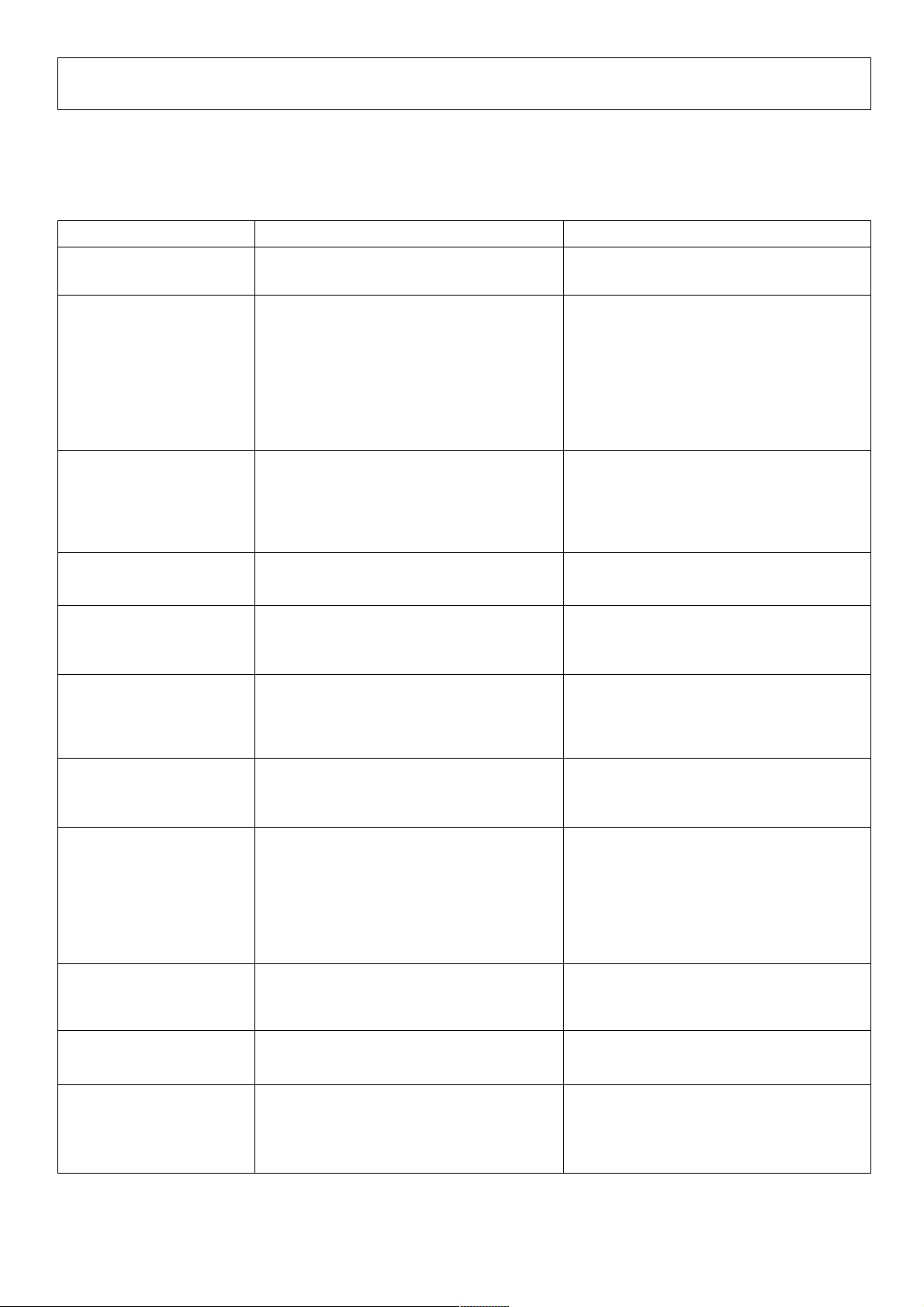
TROUBLESHOOTING
Incorrect operations are often mistaken for trouble and malfunctions. If you think there is something wrong with this component,
check the points below. Sometimes the trouble may originate from another component. Thus, also check the other electrical
appliances also in use.
If the trouble cannot be rectified even after checking the following items, contact your dealer or nearest PIONEER service center.
Problem Possible Cause Countermeasure
The power does not turn
on.
There is little or no sound.
Sound is distorted.
Can’t use cross fading.
CD player’s fader won’t
start.
Effects don’t work.
÷ The power cord has not been connected.
÷ The Input selector switch is in the wrong
position.
÷ The connection cable hasn’t been
connected properly or has been
disconnected.
÷ The terminal or plug is dirty.
÷ The rear panel MASTER LEVEL ATT.
control has been set too low.
÷ The rear panel MASTER LEVEL ATT.
control has been set too high.
÷ Input level is too high.
÷ CROSS FADER ASSIGN A and B switches
haven’t been set correctly.
÷ FADER START switch is off.
÷ The rear panel CONTROL terminal hasn’t
been connected.
÷ Effect CH. SELECT switch hasn’t been set
correctly.
÷ Effect PARAMETER 2 control (LEVEL/
DEPTH) was set to the minimum (MIN.).
÷ Connect the cord to a power outlet.
÷ Set the Input selector switch to the device
currently playing.
÷ Connect it properly.
÷ Clean and reconnect.
÷ Adjust the rear panel MASTER LEVEL ATT.
control.
÷ Adjust the rear panel MASTER LEVEL ATT.
control.
÷ Adjust the TRIM control so that the input
level approaches 0 dB on the peak level
meter.
÷ Set the CROSS FADER ASSIGN A and B
switches to the correct cross fader source.
÷ Turn on the FADER START switch.
÷ Use the control cord to connect the unit
and CD player.
÷ Correctly select the channel to which
effects should be applied.
÷ Adjust the Effect PARAMETER 2 control
(LEVEL/DEPTH).
External effector’s sound
distorted.
Can’t measure BPM.
Measured BPM values are
strange.
Measured BPM value
differs from value
indicated on CD.
Can’t use CH-4’s PHONO 4
input terminal.
Can’t apply effect mix.
Static electricity or other external interference may cause the unit to malfunction. To restore normal operation, turn the power off
and then on again.
÷ The input level from the external effector is
too high.
÷ Input level is too high or too low.
÷ BPM can’t be measured in some cases,
depending on the music.
÷ Because of different BPM measurement
methods, somewhat different values may
be indicated.
÷ A microphone has been connected to MIC
3.
÷ ASSIGN A and B switches are set to the
same channel.
÷ ASSIGN A and B switches are both set to
THRU.
÷ Lower the external effector’s output level
or adjust the return level using the Effect
PARAMETER 2 control (LEVEL/DEPTH).
÷ Adjust the TRIM control so that the input
level approaches 0 dB on the peak level
meter.
÷ Adjust input levels of other channels to
approach 0 dB.
÷ Press the TAP switch and set BPM
manually.
÷ No countermeasures necessary.
÷ Disconnect the microphone from MIC 3.
÷ Set ASSIGN A and B switches to different
channels (1-4)
÷ Set ASSIGN A and B switches to different
channels (1-4)
26
<DRB1314>
Page 27

SPECIFICATIONS
Audio Section
Input terminal (input level/impedance)
LINE 1-7 ....................................... –14 dBV (200 mV)/22 kΩ
PHONO 1-4 ..................................... –54 dBV (2 mV)/47 kΩ
MIC 1 ................................................. –54 dBV (2 mV)/3 kΩ
MIC 2, 3 ............................................. –60 dBV (1 mV)/3 kΩ
RETURN ...................................... –14 dBV (200 mV)/22 kΩ
Output terminal (output level/impedance)
MASTER OUT 1 (RCA) ............................. 0 dBV (1 V)/1 kΩ
MASTER OUT 2 (XLR) ...................... 4 dBm (1.23 V)/600 Ω
REC OUT (RCA) ..................................... –10 dBV (1 V)/1 kΩ
BOOTH MONITOR ................................... 0 dBV (1 V)/1 kΩ
SEND .....................................................–14 dBV (1 V)/1 kΩ
PHONES ................................................... 0 dBV (1 V)/22 Ω
DIGITAL OUT 1 (COAXIAL) ................................ 0.5 V/75 Ω
DIGITAL OUT 2 (COAXIAL) ................................ 0.5 V/75 Ω
Frequency characteristics
LINE/MIC ................................................... 20 Hz to 20 kHz
PHONO (RIAA) .......................................... 20 Hz to 20 kHz
SN ratio
LINE ................................................87 dB (with effects off)
PHONO ....................................................................... 77 dB
MIC .............................................................................69 dB
Electrical Section, etc.
Power supply voltage ...................................AC 120 V, 60 Hz
Power consumption ...................................................... 41 W
Operating temperature .................................... +5˚C to +35˚C
Operating humidity ...............................................5% to 85%
External dimensions ............482 (W) x 220 (D) x 107 (H) mm
12-19/32 (W) x 14-5/8 (D) x 4-7/32 (H) in
Weight .......................................................................... 7.1 kg
15 lbs 11 oz
Accessories
÷ Short-circuit pin plug ......................................................... 2
÷ Operating instructions ....................................................... 1
÷ Warranty ............................................................................ 1
For improvement purposes, specifications and design may
be subject to modification without notice.
Total harmonic distortion rate
LINE/PHONO ................................................. Below 0.02%
Cross talk (1 kHz) .................................................. Over 70 dB
Channel equalizer (LINE/PHONO/MIC 3)
HI ................................................................ +12 dB, –26 dB
MID ............................................................. +12 dB, –26 dB
LOW ........................................................... +12 dB, –26 dB
Microphone equalizer (MIC 1, 2)
TREBLE ...................................................... +12 dB, –12 dB
BASS .......................................................... +12 dB, –12 dB
Effector
DELAY and ECHO ..................................... 1 to 3500 mSec
PAN, TRANS, FILTER and FLANGER ... 10 to 16000 mSec
REVERB .............................................................. 1 to 100%
PITCH ............................................................... 0 to ±100%
27
<DRB1314>
Page 28

Should this product require service in the U.S.A. and you wish
to locate the nearest Pioneer Authorized Independent Service
Company, or if you wish to purchase replacement parts,
operating instructions, service manuals, or accessories, please
call the number shown below.
800 – 872 – 4159
Please do not ship your product to Pioneer without first calling
the Customer Support Division at the above listed number for
assistance.
PIONEER ELECTRONICS (USA), INC.
CUSTOMER SUPPORT DIVISION
Should this product require service in Canada, please contact a
Pioneer Canadian Authorized Dealer to locate the nearest Pioneer Authorized Service Company in Canada.
Alternatively, please contact the Customer Service Department
at the following address:
Pioneer Electronics of Canada, Inc.
300 Allstate Parkway
Markham, ON L3R OP2
(905) 479-4411
1 (877) 283-5901
P.O. BOX 1760, LONG BEACH,
CA 90801-1760, U.S.A.
For warranty information please see the Limited Warranty
sheet included with your product.
For warranty information please see the Limited Warranty
sheet included with your product.
PIONEER CORPORATION 4-1, Meguro 1-Chome, Meguro-ku, Tokyo 153-8654, Japan
PIONEER ELECTRONICS (USA) INC.
Multimedia and Mass Storage Division: 2265 East 220th Street, Long Beach, CA 90810, U.S.A. TEL: 800-444-OPTI (6784)
PIONEER ELECTRONICS OF CANADA, INC.
Industrial Products Department: 300 Allstate Parkway, Markham, Ontario L3R OP2, Canada TEL: 905-479-4411
Published by Pioneer Corporation.
Copyright © 2001 Pioneer Corporation.
All rights reserved.
28
<DRB1314>
Printed in China <DRB1314-A><TSZRZ/01L00000>
 Loading...