


Etek 3

01.
WARNING
02.
03.
04.
05.
06.
07.
08.
WARNING
09.
10.
2.
ADHERE STRICTLY TO THESE AND ALL OTHER
SAFETY INSTRUCTIONS AND GUIDELINES!
PLEASE READ AND UNDERSTAND ALL
INSTRUC TION MANUALS BEFORE USE.
The Eclipse Etek3 is not a toy. PAINTBALL SAFETY
RULES MUST BE FOLLOWED AT ALL TIMES.
Careless or improper use, including failure to follow
instructions and warnings within this User Manual and
attached to the Etek3 could cause death or serious
injury.
Do not remove or deface any warnings attached to
the Etek3.
Paintball industry standard eye/face/ear and head
protection designed specically to stop paintballs and
meeting ASTM standard F1776 (USA) or CE standard
(Europe) must be worn by user and any person
within range. Proper protection must be warn during
assembly, cleaning and maintenance.
Never shoot at a person who is not wearing proper
protection.
Never look directly into the barrel of the marker.
Accidental discharge into the eyes may cause
permanent injury or death. Never look into the barrel
or breech area of the Etek3 whilst the marker is
switched on and able to re.
Keep the Etek3 switched o until ready to shoot.
Treat every marker as if it is loaded and ready to re.
The electronic on/o is the markers safety, always
switch o the marker when not in use.
Always t a barrel-blocking device to the Etek3 when
11.
not in use.
Always remove all paintballs from the Etek3 when not
12.
in use on the eld of play.
13.
Never point the Etek3 at anything you do not intend
to shoot.
14.
Do not shoot at persons at close range.
Do not eld strip or remove any parts while the
15.
marker is pressurised.
Do not re the Etek3 without the bolt in the breech, as
16.
high-pressure gas will be emitted.
17.
Do not re the Etek3 without the bolt pin locked
securely in place.
18.
Never put your nger or any foreign objects into the
paintball feed tube of the Etek3.
19.
Never allow pressurised gas to come into contact with
any part of your body.
20.
Always remove the rst stage regulator and relieve
all residual gas pressure from the Etek3 before
disassembly.
21.
Always remove the rst stage regulator and relieve all
residual gas pressure from the Etek3 for transport and
storage.
22.
Always follow guidelines given with your rst stage
regulator for safe transportation and storage.
23.
Always store the Etek3 in a secure place.
ADHERE STRICTLY TO THESE AND ALL OTHER
WARNING
SAFETY INSTRUCTIONS AND GUIDELINES!
Persons under 18 years of age must have adult
24.
supervision when using or handling the Etek3.
Observe all local and national laws, regulations and
25.
guidelines.
Use only professional paintball elds where codes of
26.
safety are strictly enforced.
27.
Use compressed air/nitrogen only. DO NOT use any
other compressed gas or pressurised liquid including
.
CO
2
28.
Always follow instructions, warnings and guidelines
given with any rst stage regulator you use with the
Etek3.
29.
Use 0.68 calibre paintballs only.
30.
Always measure your markers velocity before
playing paintball, using a suitable chronograph.
Never shoot at velocities in excess of 300 feet (91.44
31.
meters) per second, or at velocities greater than local
or national laws allow.
32.
Any installations, modications or repairs should be
carried out by a qualied individual at a licensed and
insured paintball facility.
NOTE: THIS USER MANUAL MUST ACCOMPANY THE
PRODUCT IN THE EVENT OF RESALE OR NEW OWNERSHIP.
SHOULD YOU BE UNSURE AT ANY STAGE YOU MUST SEEK
EXPERT ADVICE! SEE SERVICE CENTRES PAGE 8081
THIS USERS MANUAL IS I N ENGLISH.
It contains important safety guidelines
and Instructions. Should you be unsure
at any stage, or unable to understand the
contents within this manual you must seek
expert advice.
LE MODE D’EMPLOI EST EN ANGLAIS.
Il contient des instructions et mesures de
sécurité importantes. En cas de doute, ou
s’il vous est impossible de comprendre le
contenu du monde d’emploi, demandez
conseil à un expert.
ESTE MANUAL DE USUARIOS
OPERARIOS
INGLÉS.
Contiene importantes normas de seguridad
USARIOS ESTÁ EN
e instrucciones. Si no está seguro de algùn
punto o no entiende los contenidos de este
manual debe consultar con un experto.
DIESE BEDIENUNGS UND
BENUTZERANLEITUNG IST IN
ENGLISCH.
Sie enthålt wichtige
Sicherheitsrichtlinen und bestimmungen. Solten Sie sich in
irgendeiner Weise unsicher sein, oder
den Inhalte dies Heftes nicht verstehen,
lassen Sie sich bitte von einen Experten
beraten.
QUICK GUIDE
CONTENTS
QUICK SET-UP
ORIENTATION
USING YOUR ETEK3
ADVANCED SET-UP
EMORTAL BOARD
MAINTENANCE
UPGRADING
FAULT FINDING
SERVICE CENTERS
PARTS LIST
SPARES & ACCESSORIES
INDEX
WARNING
3.

CONTENTS
4.
QUICK SETUP
Details on how to get up and running quickly with your
Etek3. This section is essential reading for everyone.
SWITCHING ON THE ETEK3......6
SWITCHING OFF THE ETEK3......6
FIRING THE ETEK3......6
THE ETEK3 CIRCUIT BOARD......6
SWITCHING ON THE ETEK3 EMORTAL BOARD......7
SWITCHING OFF THE ETEK3 EMORTAL BOARD......7
FIRING THE ETEK3......7
THE ETEK3 EMORTAL BOARD......7
USING THE BREAK BEAM SENSOR SYSTEM......8
USING THE EMORTAL BOARD BREAK BEAM
SENSOR SYSTEM......9
INSTALLING A 9V BATTERY......10
ORIENTATION
Names the component parts of the Etek3 Marker. This
section is essential reading for everyone.
THE ETEK3 LT......11
THE ETEK3 AM......12
THE ETEK3 EMORTAL BOARD......12
KNOW YOUR ETEK3......13
ETEK3 2PIECE BARREL......14
INLINE REGULATOR......15
LOW PRESSURE REGULATOR.......16
ETEK3 SOLENOID ASSEMBLY......17
THE ETEK3 NAVIGATION CONSOLE......18
OPERATIONAL OVERVIEW......19
USING THE ETEK3
More detailed information on how to use and interact
with the Etek3 via its user interface.
SETTING UP THE ETEK3......20
INSTALLING A PRESET AIR SYSTEM......20
TSLOT MOUNTING SYSTEM......21
MACROLINE HOSING AND ELBOWS......21
ATTACHING A LOADER......22
SETTING THE TRIGGER......23
ADJUSTING THE VELOCITY......24
ADJUSTING THE LPR PRESSURE......24
THE TOURNAMENT LOCK.....25
UNDERSTANDING THE BBSS OPERATION......26
THE BATTERY LEVEL INDICATOR......26
ADVANCED SETUP
In depth information on setting up the Etek3.
THE SET UP MODE......27
MODIFYING A PARAMETER......27
SET UP PARAMETERS......28
THE FIRING MODE PARAMETER......28
THE MAXIMUM ROF WITH BBSS ON CAPPED
MODES......28
THE MAXIMUM ROF WITH BBSS OFF......28
RAMP KICKIN RATE RAMP ONLY......29
RAMP RESTART TIME RAMP ONLY......29
SET UP PARAMETERS TABLE......30
DWELL......31
DEBOUNCE......31
THE BALL DETECTION TIME......31
THE RESET PARAMETER......31
THE EMORTAL BOARD
In depth information covering all aspects of the Etek3
Emortal Circuit Board.
THE EMORTAL BOARD NAVIGATION BOARD......32
USER INTERFACE......33
SWITCHING ON......33
RUN SCREEN LAYOUT......33
UNDERSTANDING THE BREAK BEAM SENSOR
SYSTEM......34
UNDERSTANDING THE TRIGGER DETECTION
INDICATOR......34
UNDERSTANDING THE LOCK INDICATOR......35
UNDERSTANDING THE BATTERY LEVEL
INDICATOR......35
THE GAME TIMER......35
THE SHOT COUNTER......35
THE ACTUAL RATE OF FIRE......36
THE PEAK RATE OF FIRE......36
THE MENU SYSTEM......36
THE MENU TREE......37
ACCESSING THE MENU SYSTEM......41

MOVING AROUND THE MENUS......41
ALTERING PARAMETERS......41
THE MAIN MENU......42
DISPLAY The Display Parameter......42
TIMER The Game Timer Menu......42
GAME The Game Time Parameter......42
START -The Timer Start Parameter......42
THE SETUP MENU......43
LOCK -The Tournament Lock Parameter......44
PRESET -The Preset Menu......44
LOAD -The Load Preset Parameter......44
SAVE -The Save Preset Parameter......45
MODE -The Firing Mode Parameter......45
ROF CAP -Rate of Fire Cap Parameter......46
MAX ROF -Maximum Rate of Fire Parameter......46
OFF ROF -Rate of Fire With BBSS O Parameter......47
RMP SET -The Ramp Settings Menu......47
TYPE -The Ramp Type Parameter......47
RATE -The Linear Ramp Rate Parameter......48
PULL NO -The Ramp Start Parameter......48
KICK IN -The Ramp Kick-In Parameter......48
SUSTAIN -The Sustain Rate Parameter......48
RESTART -The Ramp Restart Parameter......48
TIMING -The Timing Menu......49
DWELL -The Dwell parameter......49
FSD COMP -The First Shot Drop-o
Compensation Parameter
FSD DLY The First Shot Drop-o Delay Parameter......49
LIGHT -The Light Parameter......49
SLEEP -The Sleep Parameter......49
FILTER -The Filter Menu......50
DBOUNCE -The Debounce Parameter......50
EMPTY -The Breech Empty Time Parameter......50
FULL -The Breech Full Time Parameter......50
PULL TM -The Trigger Pull Time Parameter......50
REL TM -The Trigger Release Time Parameter......50
TRAININ -The Training Parameter......51
MAINTENANCE
A guide to performing routine maintenance.
CLEANING THE BREAK BEAM SENSOR
SYSTEM......52
......49
CLEANING THE INLINE REGULATOR......54
CLEANING THE LOW PRESSURE REGULATOR......56
MAINTAINING THE RAMMER......58
CLEANING AND LUBRICATING THE BOLT......60
REMOVING AND ATTACHING THE FRAME......61
THE ETEK3 TRIGGER ASSEMBLY......63
THE ETEK3 SOLENOID ASSEMBLY......65
MAINTAINING THE VALVE ASSEMBLY......67
THE ETEK3 ON/OFF PURGE SYSTEM......70
UPGRADING
Information on how to upgrade your Etek3 with Ocial
Eclipse upgrade components.
INSTALLING THE LT UPGRADE KIT......72
INSTALLING THE ETEK3 EMORTAL BOARD......75
FAULT FINDING......77
Information on how to resolve any problems that
might arise with your Etek3.
SERVICE CENTRES......80
Information on the location of your nearest Etek3
Service Centre.
PART LISTS......83
Tables of components that make up the Etek3.
WARRANTY CARD
Tear-out product registration card to be completed
and returned. Alternatively register online at
www.planeteclipse.com
SPARES & ACCESSORIES......86
Available upgrade / repair kits for your Etek3.
INDEX......88
Etek3 Manual Index
SECTI ON HEADERS O F THIS MANUAL ARE PRINTED .
THESE PAGES CONTAIN INFORMATION RE GARDING
THE EMORTAL BOARD UPGRADE.
QUICK GUIDE
CONTENTS
CONTENTS
QUICK SET-UP
ORIENTATION
USING YOUR ETEK3
ADVANCED SET-UP
EMORTAL BOARD
MAINTENANCE
UPGRADING
FAULT FINDING
SERVICE CENTERS
PARTS LIST
SPARES & ACCESSORIES
INDEX
CONTENTS
5.

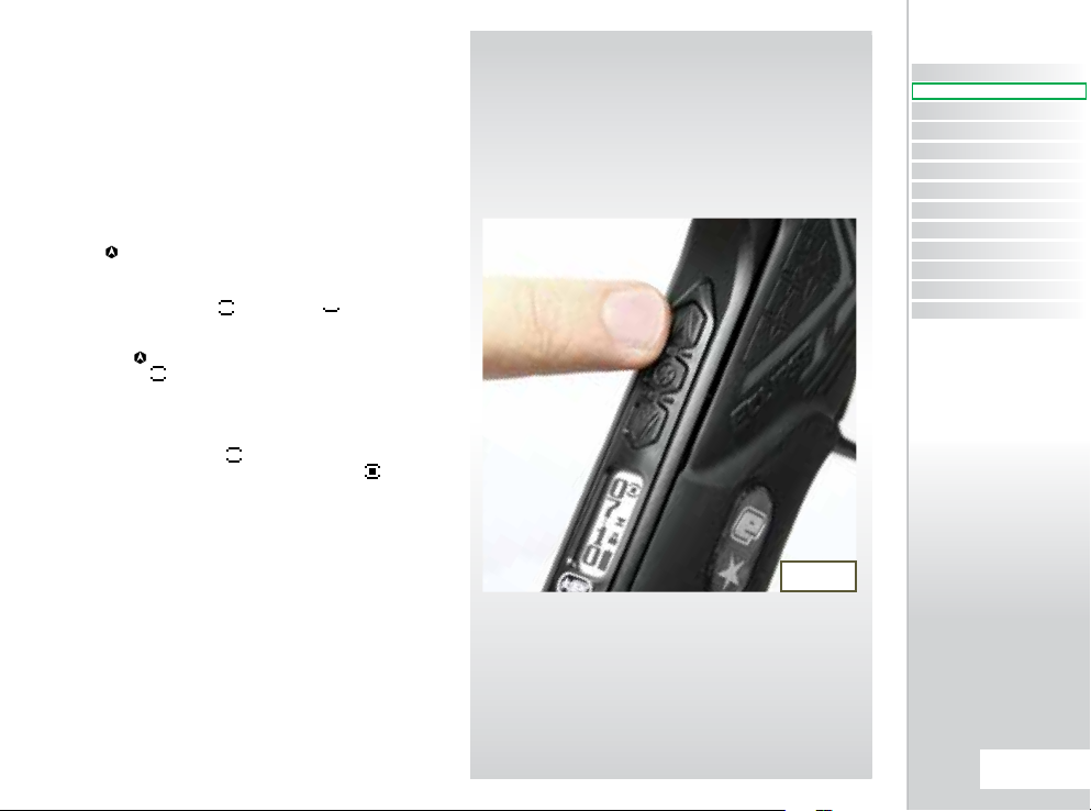
SWITCHING ON THE ETEK3
At the rear of the grip frame is the Navigation Console.
Press and hold the Select button SEE FIG URE 1.1.
Release the Select button when the LEDs light up and
your Etek3 will begin its power up sequence.
1
SWITCHING OFF THE
ETEK3
Press and hold the Select button . Release the Select
button when all three of the LEDs on the Navigation
Console turn red. The LEDs will extinguish one by one and
the Etek3 will turn o.
FIRING THE ETEK3
If the Break Beam Sensor System (BBSS) is disabled, pull the
trigger to re the Etek3. If the Break Beam Sensor System is
enabled and there is a paintball in the breech, pulling the
trigger will also re the Etek3. The entire ring sequence
is controlled electronically by the Etek3 circuit board and
solenoid, enabling any user to achieve high rates of re
easily.
THE ETEK3 LED CIRCUIT
BOARD
There are three sockets on the Etek3 circuit board, the BBSS
connector (A), the Etek3 solenoid connector (B) and the
micro-switch connector (C) SEE FIG URE 1.2.
ETEK3 LT ETEK3 AM
FIG 1.1
B
A
C
FIG 1.2
QUICK SET-UP
6.
SWITCHING ON THE ETEK3
WARNING
EMORTAL BOARD
To switch on the Etek3 press and hold the button until
the screen lights up and the Emortal board begins its
power up sequence FIGURE 2.1.
1,2
SWITCHING OFF THE
ETEK3 EMORTAL BOARD
Press and hold the button until the display shows TURN
OFF.
Release the button and re-press it to turn o the
Etek3.
FIRING THE ETEK3
If the Break Beam Sensor System (BBSS) is disabled, pull the
trigger to re the Etek3. If the Break Beam Sensor System is
enabled and there is a paintball in the breech, pulling the
trigger will also re the Etek3. The entire ring sequence is
controlled electronically by the Etek3 Emortal board and
solenoid, enabling any user to achieve high rates of re
easily.
WARNING: THE BACKLIG HT ON THE LCD DISP LAY
TURNS OFF AFT ER A PERIOD O F TIME. WHEN THIS
HAPPENS THE MAR KER IS STILL ON AND ABLE TO FIRE.
SEE PAGE 49 ON A DJUSTING THE B ACKLIGHT
FIG 2.1
A
C
QUICK GUIDE
CONTENTS
QUICK SET-UP
QUICK SET-UP
ORIENTATION
USING YOUR ETEK3
ADVANCED SET-UP
EMORTAL BOARD
MAINTENANCE
UPGRADING
FAULT FINDING
SERVICE CENTERS
PARTS LIST
SPARES & ACCESSORIES
INDEX
THE ETEK3 EMORTAL
BOARD
There are three sockets on the Etek3 circuit board, the BBSS
connector (A), the Etek3 solenoid connector (B) and the
micro-switch connector (C) SEE FIG URE 2.2.
1
When the Etek3 is turned on, the Break Beam Sensor System
is automatically enabled.
2
By continuing holding down the button when turning
on the Emortal board the software version number will be
displayed.
B
FIG 2.2
QUICK SET-UP
7.
USING THE BREAK BEAM
SENSOR SYSTEM
When the Etek3 is powered up, the Break Beam Sensor
System (BBSS) is automatically enabled.
To switch o the Break Beam Sensor System, push and
hold the Select button for 0.5 seconds. The ‘E’ on the
Navigation Console will ash purple indicating that the
Break Beam Sensor System has been disabled.
To switch on the Break Beam Sensor System, push and
hold the Select button for 0.5 seconds. The ‘E’ on
the Navigation Console will ash either yellow (no ball
detected) or light blue (ball detected) indicating that the
Break Beam Sensor System has been enabled.
Additional features of the Etek3 Break Beam Sensor
System are covered in full in the ‘Understanding the BBSS
Operation’ section on Page 26 of this User Manual.
YELLOW LIGHT NO
BALL DETECT ED
PURPLE LIGHT BBSS
DISABLED
LIGHT BLUE LIGHT
BALL DETECT ED
QUICK SET-UP
8.
USING THE EMORTAL
BOARD BREAK BEAM
SENSOR SYSTEM
The Break Beam Sensor System (BBSS) is used to detect
when a paintball is ready to re from the Etek3. If no
paintball is ready then the BBSS will inhibit the Etek3 from
ring. This prevents the Etek3 from ‘chopping’ paintballs
that are not fully loaded into the marker.
To switch o the Break Beam Sensor System, press and
hold the button for 0.5 second SEE FIGURE 3.1.
The break beam sensor system indicator on the top right of
the LCD will change from (enabled) to (disabled).
To switch the Break Beam Sensor System back on, press
and hold the button for one second. The indicator will
change back to .
When the Break Beam Sensor System is enabled, the
indicator will change depending on whether the system
has detected a ball or not. When no ball has been detected
the indicator looks like this when a ball has been
detected the indicator changes to look like this .
Additional features of the Emortal Board’s Break Beam
Sensor System are covered in full on page 34 of this user
manual.
FIG 3.1
QUICK GUIDE
CONTENTS
QUICK SET-UP
QUICK SET-UP
ORIENTATION
USING YOUR ETEK3
ADVANCED SET-UP
EMORTAL BOARD
MAINTENANCE
UPGRADING
FAULT FINDING
SERVICE CENTERS
PARTS LIST
SPARES & ACCESSORIES
INDEX
QUICK SET-UP
9.
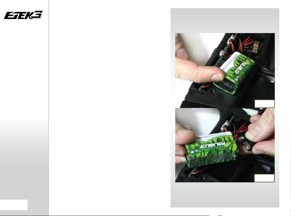
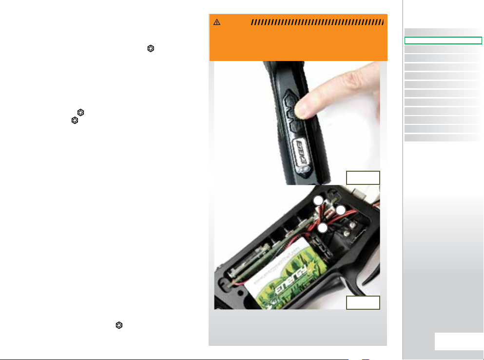
INSTALLING A 9V BATTERY
Ensure that the Etek3 is switched o. Place the marker on a
at surface in front of you with the feed tube furthest away
from you and the barrel pointing to the right.
Using a 5/64” (2mm) hex key, remove the three
countersunk screws that holds the rubber grip onto the
grip frame. Peel the rubber grip to the right to expose the
electronics within the grip frame.
If present remove the existing 9 volt battery by sliding your
thumb into the recess provided below the battery and
lever the battery gently out of the frame SEE FIG URE 4.1.
On top of the battery you will see the battery connector
and wire that is used to connect the battery to the circuit
board. Gently separate the battery connector from the
battery, so that the existing battery can be disposed of
accordingly and taking a new 9 volt Alkaline battery (type
PP3, 6LR61, MN1064)1 connect it to the battery connector
SEE FIGURE 4.2.
The battery will only connect to the battery connector
one way. If you are unsure of how to install a new battery
please contact your nearest Eclipse Service Centre.
Ensure that all of the wires are within the recess of the
frame and not trapped in micro-switch, then replace the
rubber grip and tighten the countersunk grip screws using
the 5/64th” (2mm) hex key.
DO NOT OVERTIGHTEN THE SCREWS.
1
Do not use rechargeable batteries or low quality batteries.
FIG 4.1
FIG 4.2
QUICK SET-UP
10.
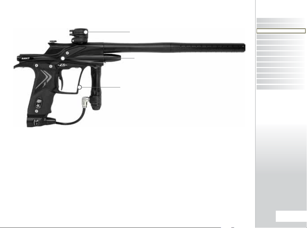
THE ETEK3 LT
GRN FEED NECK AND FEED
LEVER
GRN EYE COVERS
GRN GRIP FRAME
THE ETEK3 LT SHOWN ABOVE MAY NOT EXACTLY
MATCH THE ETEK3 LT YOU HAVE PURCHASED
Your Eclipse Etek3 LT comes standard with:
GRN (Glass Reinforced Nylon) composite grip frame
GRN composite eye covers
GRN composite feedneck and feed lever
These components are upgradable to the same spec level as the Etek3 AM by installing the Etek3 LT Upgrade Kit which
contains:
Aluminium grip frame
Aluminium eye covers
Aluminium feedneck and feed lever
Instructions on installing these components can be found on pages 72-74
QUICK GUIDE
CONTENTS
QUICK SET-UP
ORIENTATION
ORIENTATION
USING YOUR ETEK3
ADVANCED SET-UP
EMORTAL BOARD
MAINTENANCE
UPGRADING
FAULT FINDING
SERVICE CENTERS
PARTS LIST
SPARES & ACCESSORIES
INDEX
All other parts of the Etek3 LT (other than the GRN parts) are manufactured from exactly the same materials and nishes
you will nd on the Etek3 AM.
ORIENTATION
11.
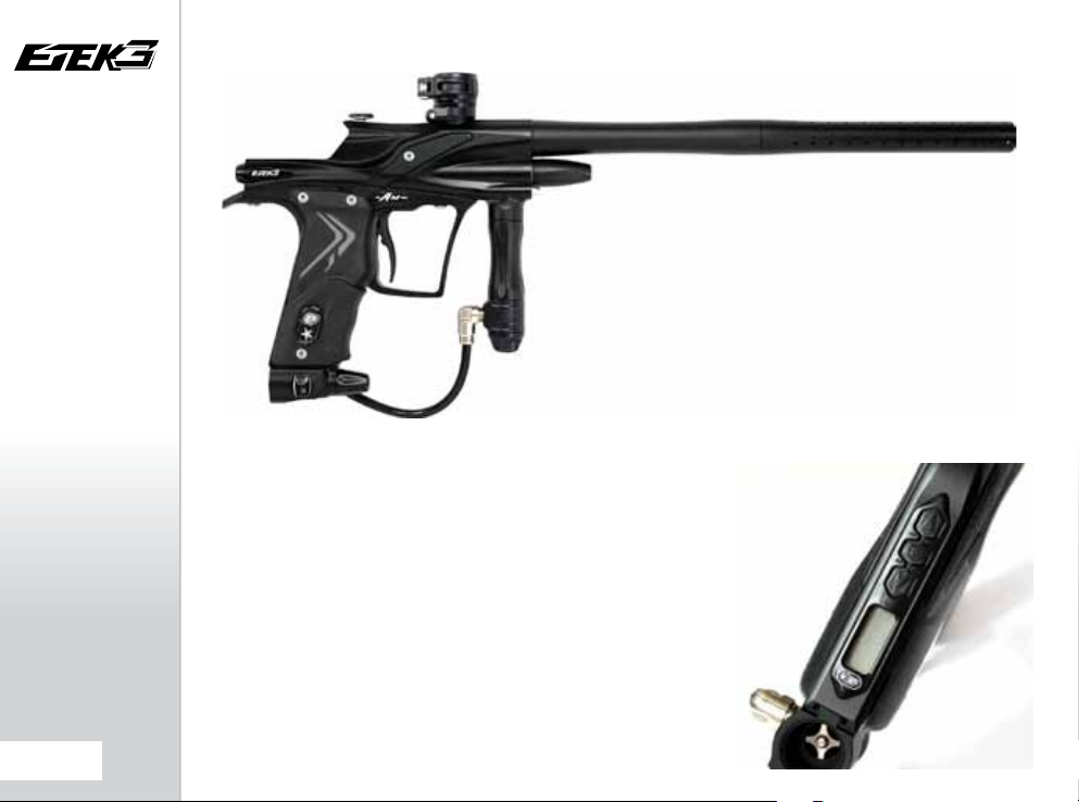
ORIENTATION
THE ETEK3 AM
THE ETEK3 AM SHOWN ABOVE MAY NOT EXACTLY
MATCH THE ETEK3 AM YOU HAVE PURCHASED
The Eclipse Etek3 AM is intrinsically identical to the Etek3 LT but comes
standard with an ‘ALL METAL’ construction. All the parts on the AM are made
from the same materials and with the same nishes found on the Ego and Geo
range of markers.
The metal frame of the Etek3 AM or upgraded Etek3 LT (upgraded with Etek3
LT upgrade kit) allow for the installation of the Etek3 Emortal Board. This is a
fully functional LCD board with a similar menu system to that of the Ego and
Geo markers.
Instructions on using the Emortal board can be found starting on pages 32-51.
this is essential reading for users with the Emortal board tted. Users with an
Emortal Board tted will have a console in the back of their Etek3 frame like the
one shown opposite.
THE ETEK3
EMORTAL BOARD
12.
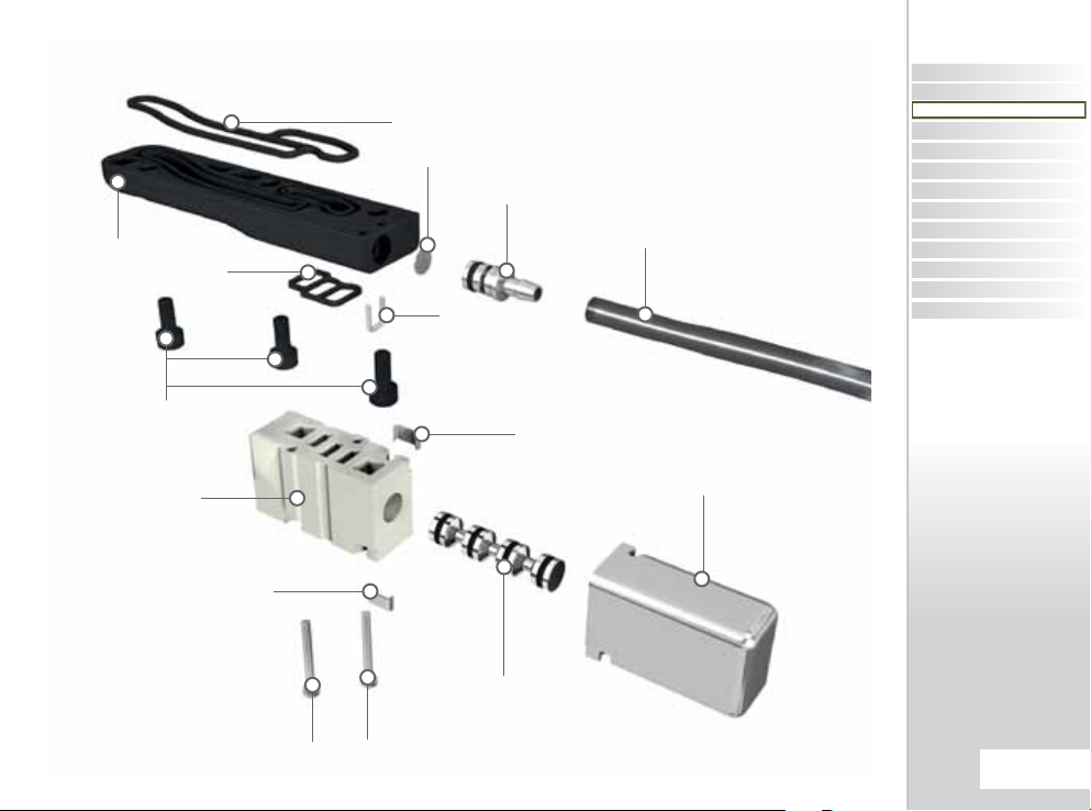
KNOW YOUR ETEK3
BOLT PIN
BOLT
RAMMER
HOUSING
RAMMER
RAMMER CAP
G
QUICK GUIDE
CONTENTS
FEED LEVER
BODY
FEEDNECK
TORPEDO
EXHAUST
VALVE
VALVE
SPRING
LPR BODY
A
B
VALVE
PLUG
C
D
LPR CAP
FRM SCREW
QUICK SET-UP
ORIENTATION
ORIENTATION
USING YOUR ETEK3
ADVANCED SET-UP
EMORTAL BOARD
MAINTENANCE
UPGRADING
FAULT FINDING
SERVICE CENTERS
PARTS LIST
SPARES & ACCESSORIES
INDEX
FRAME ASSEMBLY
BATTERY
FRAME
SCREW
OOPS
OOPS PIN
INSERT
OOPS
BODY
E
F
FRAME
SCREW
OOPS KNOB
OOPS SCREWS
INLINE REGULATOR
ASSEMBLY
MACRO LINE
ELBOW
EYE COVER SCREW
SOLENOID ASSEMBLY
TRIGGER RETAINING CLIP
CIRCUIT BOARD
SOLENOID MANIFOLD ASSEMBLY
EYE COVER
TRIGGER
A
B
C
D
E
F
G
ORIENTATION
13.
ETEK3 2PIECE BARREL
WARNING
THE BORE SIZE OF YOUR BARR EL MAY VARY ACCORDING TO THE
MODEL OF ETEK3 YOU HAVE
Your Eclipse Etek3 comes as standard with a 14 inch 2-piece barrel.
The barrel screws into the body of the Etek3 using a
meaning that if you hold the Etek3 pointing away from you the barrel
screws into the body in a counter-clockwise direction.
The barrel comprises of two parts, a barrel back and a barrel front .
The two parts are joined together with a left hand thread meaning that
if you hold the barrel, with the back nearest you, the front unscrews in a
counter-clockwise direction. The bore size of the barrel back is engraved
at the end of the barrel back .
On the barrel back there is a 016 NBR 70 o-ring which prevents the
barrel from vibrating loose from the Etek3 body when the marker is
red. There is also a 015 NBR 70 o-ring on the barrel front helps with
alignment when the two sections are screwed together.
Replace and lubricate these o-rings with Eclipse Grease as necessary.
C
right hand thread
A
D
E
A
B
B
E
14.
ORIENTATION
D
C
WARNING: THE ETEK3 WIL L ONLY ACCEPT COC KER
THREADED BAR RELS SUCH A S THE ECLIPSE SH AFT 3
BARREL. DO NOT USE ANY OTHER TYPE O F BARREL
THREAD.
INLINE REGULATOR
WARNING
INLINE REGULATOR PISTON
#008 NBR 70
#011 NBR 70
INLINE REGULATOR TOP
#015 NBR 70
INLINE REGULATOR
ADJUSTER SCREW
#016 NBR 70
#015 NBR 90
INLINE REGULATOR SPRING
INLINE REGULATOR SWIVEL
QUICK GUIDE
CONTENTS
QUICK SET-UP
ORIENTATION
ORIENTATION
USING YOUR ETEK3
ADVANCED SET-UP
EMORTAL BOARD
MAINTENANCE
UPGRADING
FAULT FINDING
SERVICE CENTERS
PARTS LIST
SPARES & ACCESSORIES
INDEX
INLINE REGULATOR BOTTOM
WARNING: THE SWIVEL CAN ONLY BE REMOVED
AFTER THE MACROLINE FIT TING HAS FI RST BEEN
REMOVE D FROM THE INLI NE REGULATOR SWIVEL.
ORIENTATION
15.
LOW PRESSURE REGULATOR
#14x2 NBR 70
#016 NBR 70
OR
LPR BODY
#010 NBR 70
ORIENTATION
16.
LPR CAP
LPR ADJUSTER SPRING
#007 NBR 70
LPR PISTON
LPR ADJUSTER SCREW
LPR PISTON SPRING
#013 NBR 70
ETEK3 SOLENOID ASSEMBLY
MANIFOLD/BODY
GASKET
FILTER
SOLENOID MANIFOLD
MANIFOLD/SOLENOID
GASKET
BARB CLIP
M2.5x5 MANIFOLD
RETAINING SCREWS
SOLENOID BODY
SOLENOID CLIP
INLET BARB
SOLENOID CLIP
SPOOL SHAFT
LP HOSE
SOLENOID PILOT
SECTION
QUICK GUIDE
CONTENTS
QUICK SET-UP
ORIENTATION
ORIENTATION
USING YOUR ETEK3
ADVANCED SET-UP
EMORTAL BOARD
MAINTENANCE
UPGRADING
FAULT FINDING
SERVICE CENTERS
PARTS LIST
SPARES & ACCESSORIES
INDEX
M1.6X16 SOLENOID
RETAINING SCREWS
ORIENTATION
17.
THE ETEK3 NAVIGATION
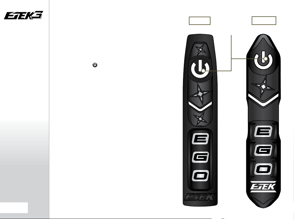
CONSOLE
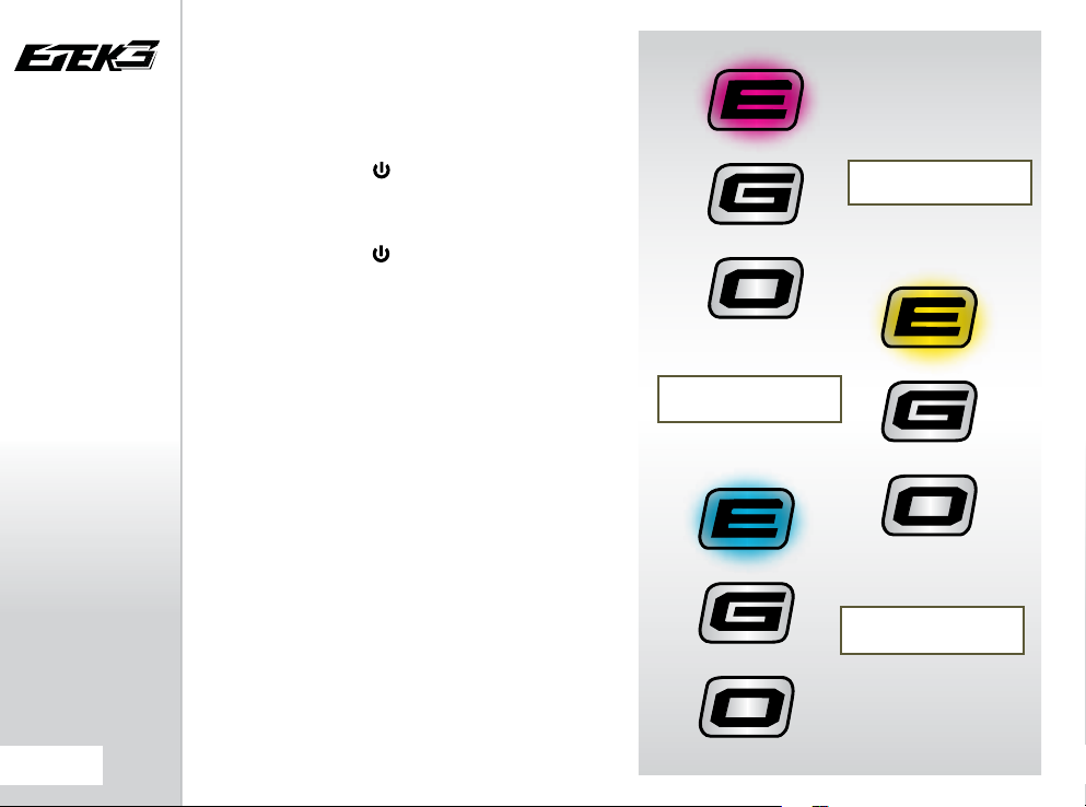
The Etek3 utilises multi coloured LEDs to display all of
the information that the user requires via the Etek3s
Navigation Console.
Each area of the Navigation Console is used to perform
dierent functions and display dierent information as
outlined below:
The Select button is used to:
- Switch the Etek3 on and o.
- Switch the BBSS (eye system) on and o.
- To scroll through parameters and edit parameters.
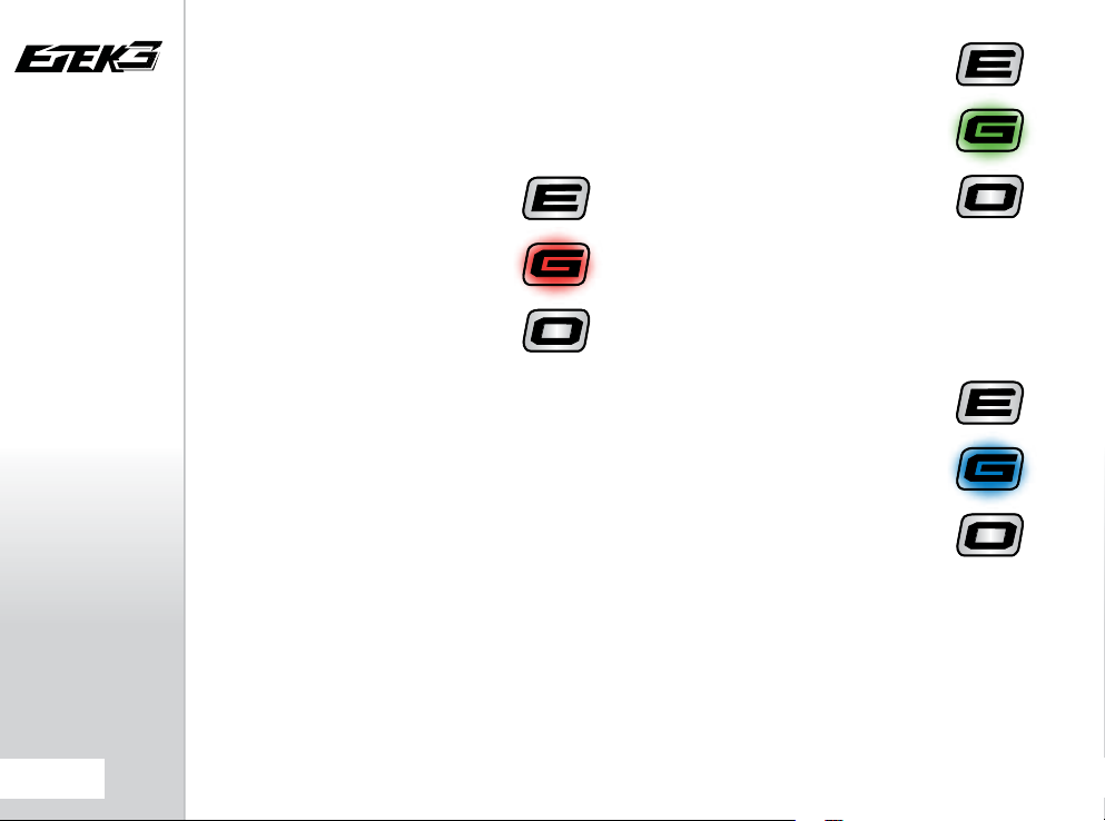
The “E” on the Navigation Console is used to:
- Display the status of the BBSS (eye system).
- Display the value of a parameter in tens (10 - 90)
The “G” on the Navigation Console is used to:
- Display the value of a parameter in units (0 - 9)
- Display the status of the battery.
The “O” on the Navigation Console is used to:
- Display the value of a parameter in tenths (0.0 - 0.9)
As a combined unit the “E”, “G” and “O” are also used to:
- Display power up and power down status.
- Display tournament lock status.
- Display that factory settings have been restored
- To conrm whether a parameter value has been accepted
or rejected.
ETEK3 LT
SELEC T
BUTTON
ETEK3 AM
ORIENTATION
18.

OPERATIONAL OVERVIEW
Below is a brief overview of what happens during
the Etek3 ring cycle. The location of parts discussed
in the text below can be found on page 82-85.
Assuming the Etek3 is gassed up and turned on,
FIGURE 5.1 shows the marker in its idle position. The
rammer is held in its rear position with pressurised
air from the LPR directed through the solenoid to
the front of the rammer. The valve chamber is full of
pressurised air from the inline regulator.
Providing a ball is in the breach, when the trigger
is pulled, a signal is sent to the solenoid which
redirects the supply of air from the front of the
rammer to the rear, which pushes the rammer and
bolt forward toward the valve FIGURE 5.2. As this
happens the air in front of the rammer is vented out
through an exhaust port in the solenoid manifold.
The rammer makes contact with the valve stem
and continues to be pushed forward, now pushing
the valve forward with it. This breaks the valve seal
allowing pressurised air to ow up through the
valve and into the bolt and vent down the barrel,
propelling a ball. FIGURE 5.3
The time that the rammer is held in this forward
position is dependant on the
The longer the dwell time the longer the Etek3
vents gas down the barrel. When this dwell time
has elapsed, the solenoid redirects the supply of air
from the back of the rammer to the front, pushing
the rammer and bolt back to the rear position. This
loss of forward force allows the valve to re-seal and
the valve chamber is re-pressurised. As the rammer
moves back air behind it is vented through an
exhaust port in the solenoid manifold FIGURE 5.4.
The Etek3 has now completed one cycle and is
ready to re again.
DWELL
parameter.
Inline Regulator Supply
Inline Regulator Supply
Inline Regulator Supply
Inline Regulator Supply
Air supply
from Solenoid
Air venting
Air venting
Air supply
from Solenoid
FIG 5.1
Air venting
FIG 5.2
Air supply
from Solenoid
FIG 5.3
Air supply
from Solenoid
FIG 5.4
Air venting
QUICK GUIDE
CONTENTS
QUICK SET-UP
ORIENTATION
ORIENTATION
USING YOUR ETEK3
ADVANCED SET-UP
EMORTAL BOARD
MAINTENANCE
UPGRADING
FAULT FINDING
SERVICE CENTERS
PARTS LIST
SPARES & ACCESSORIES
INDEX
ORIENTATION
19.
SETTING UP YOUR ETEK3
WARNING
WARNING
WARNING
Before you can begin to use your Etek3, you will need to
attach an air system and a paintball loader.
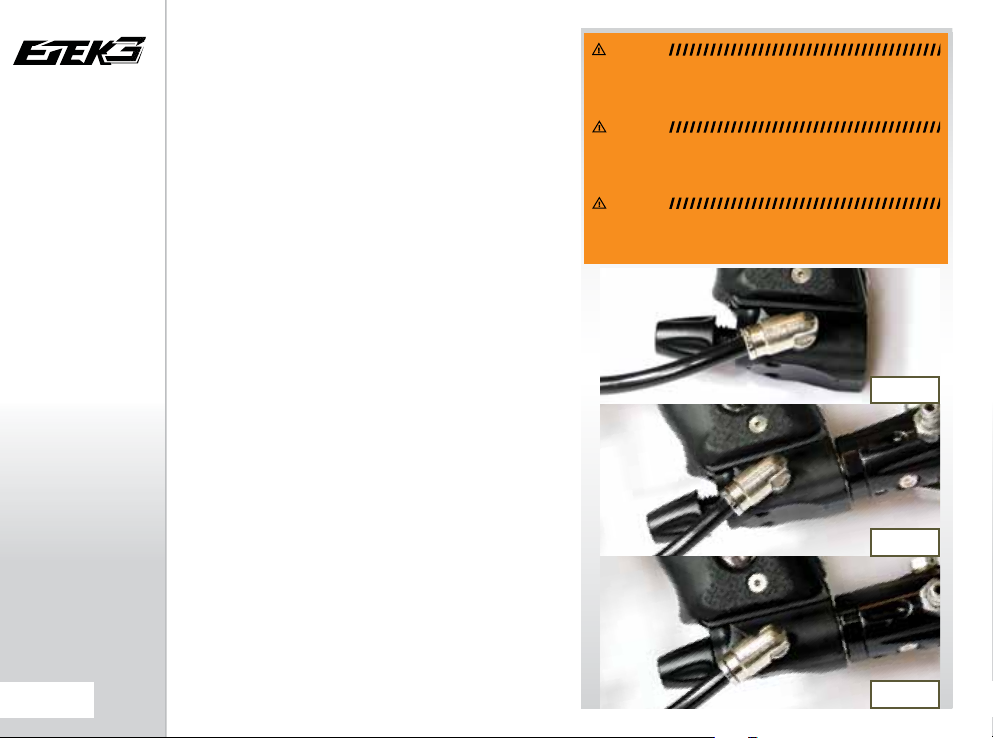
INSTALLING A PRESET AIR
SYSTEM
Every Etek3 comes complete with an Eclipse On/O Purge
System (OOPS) which provides a direct connection for
a preset air system. Before screwing the air system into
the OOPS ensure that the On/O knob is wound out
approximately half way SEE FIGUR E 6.1. Be careful not to
unscrew the On/O knob too far as it will come completely
o the OOPS. If this happens, replace the On/O knob
by screwing it back onto the OOPS body in a clockwise
direction.
Screw the preset air system1 into the OOPS SEE FIGURE
6.2
so that the bottle screws in all the way and is tight.
Slowly turn the On/O knob in a clockwise direction
allowing the OOPS to depress the pin of the preset air
system causing the Etek3 to become pressurised, providing
that there is sucient air in your tank SEE FIGURE 6.3.
You have now installed a preset air system onto your Etek3.
WARNING: MAKE SURE THE MARKER IS TURNED OF F
AND THAT NO PAINTBALLS A RE IN THE MARKER OR
LOADER BEFORE INSTALLING AN AIR S YSTEM.
WARNING: ALWAYS RELIEVE ALL RESIDUAL GAS
PRESSURE FRO M THE ETEK3 BEFORE UNSC REWING THE
WARNING: THE ETEK3 C ANNOT BE USED WI TH CO2,
IT CAN ONLY BE POWERED BY COMP RESSED AIR O R
PRESET AIR SYSTEM.
NITROGEN.
FIG 6.1
FIG 6.2
20.
USING YOUR ETEK3
1
We recommend using a preset air system with a high pressure
output to achieve optimum performance from the Etek3,
however most good quality Low pressure output systems will
also work on the Etek3.
FIG 6.3

TSLOT MOUNTING
WARNING
SYSTEM
The Etek3 utilises a T-slot arrangement to mount the OOPS
to the bottom of the frame. The T-slot is an improvement
over the dovetail mounting system found on most
paintball markers, and is much more able to withstand the
rigours of modern tournament paintball.
TSLOT
MOUNT
MACROLINE HOSING AND
ELBOWS
To aid the longevity of your macroline hosing, it is very
important to remove it from (and install it back into) the
ttings in the correct manner:
Pull back the collet section of the macroline tting and
keep the collet depressed.
Pull the macroline hose out of the macroline tting and
release the collet.
Before installing the macroline hose into the macroline
tting ensure that the end has been trimmed correctly to
ensure a tight t in the tting.
IF YOU EVER REMOVE THE MACROL INE HOSE FROM
THE FITTING, ALWAYS C HECK THE CONDITION OF
YOUR MACROLINE HO SING AND IF I T IS WORN OR THE
WRONG LENGTH REPLACE IT IMMEDIATELY.
QUICK GUIDE
CONTENTS
QUICK SET-UP
ORIENTATION
USING YOUR ETEK3
USING YOUR ETEK3
ADVANCED SET-UP
EMORTAL BOARD
MAINTENANCE
UPGRADING
FAULT FINDING
SERVICE CENTERS
PARTS LIST
SPARES & ACCESSORIES
INDEX
USING YOUR ETEK3
21.
ATTACHING A LOADER
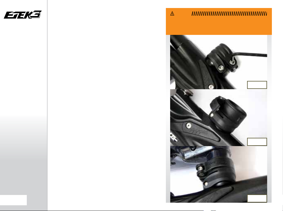
WARNING
Using a 5/32” hex key, turn the top screw of the clamping
feed neck counter clockwise SEE FIGURE 7.1.
Release the clamping lever on the feed neck SEE FIGURE
7.2
and test to see if your loader can easily be pushed
into the top of the feed neck. If the loader cannot easily
be pushed into the feed neck, loosen the top screw of
the clamping feed neck a little more by turning it counter
clockwise using a 5/32” hex key SEE FIGU RE 7.1.
When you have managed to push your loader into the
clamping feed neck, close the clamp to secure it rmly in
place SEE FIG URE 7.3. If the loader is loose then you will
need to release the clamp, tighten the top screw slightly by
turning it clockwise with a 5/32” hex key to close the clamp.
Repeat this process as necessary to secure your loader in
place.
You have now attached a loader to your Etek3. Once you
have lled your loader and air tank you will then be ready
to begin using your Etek3.
WARNING: DO NOT OVER TIGHTEN THE CLAMPING F EED
NECK AS THIS MAY DAMAGE THE LOADER OR FEED NECK
ITSELF.
FIG 7.1
FIG 7.2
22.
USING YOUR ETEK3
FIG 7.3
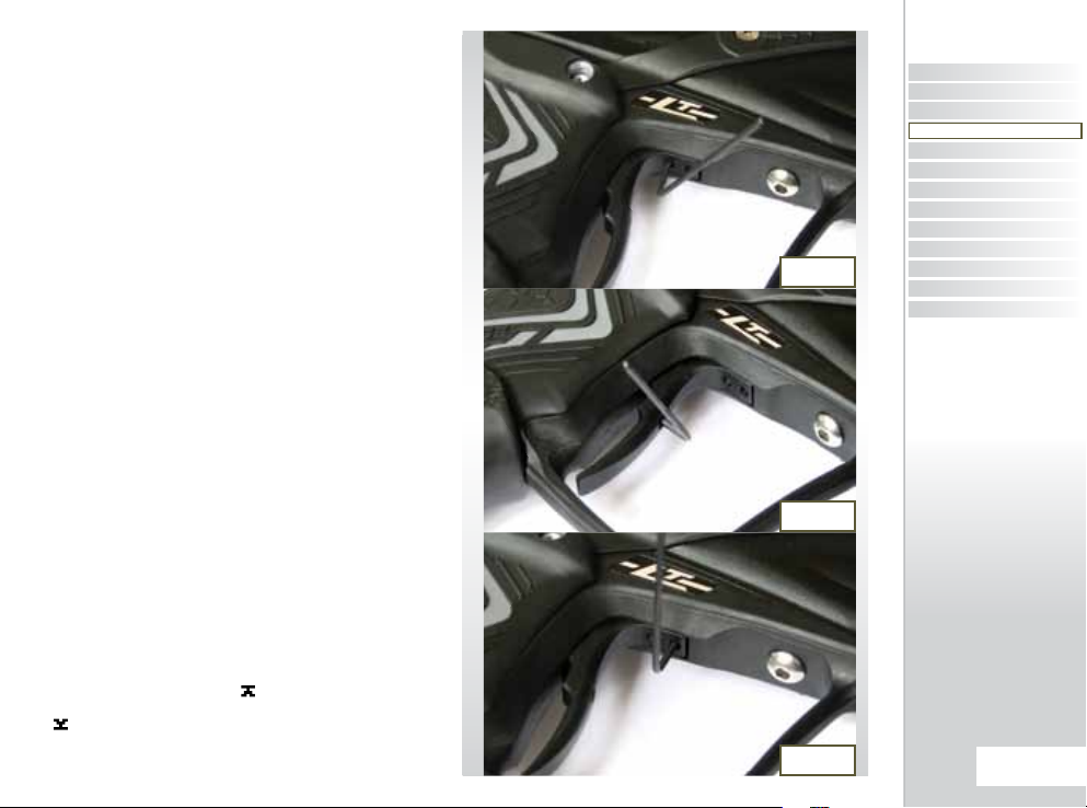
SETTING THE TRIGGER
There are three adjustment points on the trigger – the
Front Stop Trigger Screw, the Rear Stop Trigger Screw, and
the Magnet Return Screw.
As standard each Etek3 comes with a factory set trigger
travel of approximately 2mm in total length; one millimeter
of travel before the ring point and one millimeter of travel
after the ring point.
The Front Stop Trigger Screw is used to set the amount
of trigger travel prior to the marker ring. Turn this screw
clockwise to reduce the amount of travel. Do not turn the
screw too far or the trigger will be pushed past the ring
point and the marker will not work. Turn this screw counter
clockwise to increase the amount of trigger travel SEE
FIGURE 8.1
The Rear Stop Trigger Screw is used to set the amount of
travel after the marker has red. Turn this screw clockwise
to reduce the amount of travel. Do not turn the screw too
far or the trigger will be prevented from reaching its ring
point and the marker will not work. Turn this screw counter
clockwise to increase the amount of travel SEE FIGURE
8.2
The Magnet Return Screw is used to adjust the amount of
return force with which the trigger is returned. Turn the
screw clockwise to increase the amount of magnet return
force. Do not turn the screw to far or it will negate the
position of the Front Stop Trigger Screw. Turn the screw
counter clockwise to reduce the amount of spring tension
SEE FIGURE 8.3
EMORTAL BOARD USERS ONLY
When setting the trigger it is important to ensure that the
electronic trigger detection is working correctly. When the
trigger is fully depressed the Trigger Detection Indicator
(TDI) should point upwards . When the trigger
is fully released the TDI should point downwards
. For more information, see ‘Understanding the Trigger
Detection Indicator’ (TDI) on page 34 and the Filter menu
on page 50.
.
.
FIG 8.1
FIG 8.2
FIG 8.3
QUICK GUIDE
CONTENTS
QUICK SET-UP
ORIENTATION
USING YOUR ETEK3
USING YOUR ETEK3
ADVANCED SET-UP
EMORTAL BOARD
MAINTENANCE
UPGRADING
FAULT FINDING
SERVICE CENTERS
PARTS LIST
SPARES & ACCESSORIES
INDEX
USING YOUR ETEK3
23.

ADJUSTING THE VELOCITY
When using your Etek3, you may wish to change the
velocity at which your Etek3 is ring. This is done by
inserting a 1/8" hex key into the adjuster screw at the
bottom of your Etek3 inline regulator and adjusting it
accordingly SEE FIGURE 9.1. By turning this adjuster
screw clockwise you decrease the output pressure of the
inline regulator and consequently the velocity, by turning
the adjuster screw counter clockwise you increase the
output pressure of the inline regulator and consequently
the velocity1 . On the bottom of the inline regulator there
are engraved arrows to illustrate which direction to turn
the hex key to make the relevant adjustment.
ADJUSTING THE LPR
PRESSURE
When using your Etek3, you may wish to change the
output pressure of your LPR. This is easily done by inserting
a 1/8" inch hex key into the adjuster screw at the front
and adjusting it accordingly SEE FIGUR E 9.2. However
we recommend that the LPR screw be left set 2 turns in
(clockwise) from the screw being ush with the front of the
LPR cap.
By turning the adjuster screw clockwise, you decrease the
output pressure of your LPR and consequently reduce the
pressure driving your rammer back and forth. By turning
the adjuster screw counter clockwise, you increase the
output pressure of your LPR and consequently increase the
pressure driving your rammer back and forth.
2
FIG 9.1
FIG 9.2
USING YOUR ETEK3
24.
1
After each adjustment re two clearing shots to gain an
accurate velocity reading. Never exceed 300fps.
2
Turning the adjuster screw in too far will prevent the Etek3
from ring.

THE TOURNAMENT LOCK
The Etek3 has an electronic tournament lock which, once
enabled, prevents the user from making any changes to
the setup parameters of the marker. This tournament lock
complies with the rules of all major tournaments and must
be enabled prior to entering the eld of play in order to
avoid penalties.
To enable the tournament lock -
1. Unscrew the three screws from the right hand side of the
rubber grips SEE FIGURE 10.1 using a 5/64” hex key.
2. Turn on the Etek3.
3. Locate and press the Lock button on the circuit board
SEE FIGURE 10.2. The Navigation Console will ash green
to indicate that the tournament lock has been enabled.
4. Replace the three rubber grip screws using a 5/64” hex
key.
QUICK GUIDE
CONTENTS
QUICK SET-UP
ORIENTATION
USING YOUR ETEK3
USING YOUR ETEK3
ADVANCED SET-UP
EMORTAL BOARD
MAINTENANCE
UPGRADING
FAULT FINDING
SERVICE CENTERS
PARTS LIST
SPARES & ACCESSORIES
INDEX
To disable the tournament lock –
1. Unscrew the three screws from the right hand side of the
rubber grips SEE FIGURE 10.1 using a 5/64” hex key.
2. Turn on the Etek3.
3. Locate and press the Lock button on the circuit board
SEE A IN FI GURE 10.2. The Navigation Console will ash
red to indicate that the tournament lock has been disabled.
4. Replace the three rubber grip screws using a 5/64” hex
key.
FIG 10.1
A
FIG 10.2
USING YOUR ETEK3
25.
USING YOUR ETEK3
UNDERSTANDING THE
BBSS OPERATION
The Etek3 displays the status of the Break Beam Sensor System using the ‘E’ area of the Navigation Console as follows:
INDIC ATIO N BREECH SENSO R STATUS
Flashing Yellow
Flashing Light Blue
Flashing Purple
Fast Flashing Purple
Any changes to the Breech Sensor Status will be displayed
immediately. This provides valuable feedback to the user.
An example of this is when you are shooting a string of shots
with the BBSS enabled, the “E” on the Navigation Console
will alternate in colour from Yellow (no paintball detected)
to Light Blue (paintball detected). In this instance too much
yellow would indicate that your chosen loader cannot keep
up with how fast you are shooting and is consequently
slowing down your rate of re.
The BBSS is able to switch itself o in the event that a
blockage or contamination prevents it from functioning
correctly. This is represented by a fast ashing purple light
in the “E” area of the Navigation Console. The Etek’s ROF will
be capped at 7.5bps. In this instance, the BBSS will switch
itself back on once the blockage is cleared and the correct
operation of the BBSS can then be resumed
BBSS enabled (On), no paintball
detected - marker will not re.
BBSS enabled (On), paintball
detected - marker will re.
BBSS disabled (O) - marker will
re.
Blockage detected, BBSS
temporarily disabled (O) marker will re.
THE BATTERY LEVEL
INDICATOR
The Etek3 displays the status of the battery using the ‘G’
area of the Navigation Console. When the battery is fresh ‘G’
LED ash green.
As the battery is drained the ‘G’ LED will change colour
from green to yellow.
When the battery reaches a level where it will no longer
function reliably, the ‘G’ LED will start to ash red. At this
point the battery must be changed for a new one. For
instructions on installing a new battery see page 10.
26.
THE SET UP MODE
The SET UP MODE can only be entered if tournament lock is
o. See page 25 for details on the tournament lock.
To activate the SET UP MODE, rstly ensure that the Etek3
is switched o. Pull and hold the trigger, and whilst the
trigger is still pulled push and hold the button until
the ‘E’ and the ‘O’ on the Navigation Console alternately
ash white to indicate entry to SET UP MODE. When you
have entered the SET UP MODE, the ‘G’ on the Navigation
Console will turn red to indicate the rst parameter of the
SET UP MOD E. You can now release the trigger.
Press the button to scroll through each of
the parameters on the SET UP MODE:
COLOUR
Red
Green
Blue
White
Dark Red
Purple
Light Blue
Yellow
To see the value that any setup parameter is set to, pull and
release the trigger. the value will be indicated by ashing
the tens on the ‘E’ LED, the units on the ‘G’ LED and tenths
on the ‘O’ LED. E.g. 14.5 would be indicated as follows-
1 FLAS H OF THE ‘E’ L ED
4 FLAS HES OF THE ‘G’ LE D
5 FLAS HES OF THE ‘O’ L ED
A zero is indicated by no ashes. E.g. 3.0 would be
indicated as follows:
0 FLAS HES OF THE ‘E’ LED
3 FLAS HES OF THE ‘G’ LE D
0 FLAS HES OF THE ‘O’ L ED
PARAMETE R
Firing Mode
Maximum ROF with
BBSS on (for capped
modes only).
Maximum ROF with
BBSS o.
Ramp Kick-in Rate
(ramp only)
Ramp Restart Time
(ramp only)
Dwell
Debounce
Ball Detection Time
RANGE
1 to 3
4.0 bps to 15.4
bps
4.0 bps to 15.4 bps
5.0 pps to 10.0 pps
0.0 to 1.0 s
1.0 ms to 15.0 ms
1 to 10
1 ms to 10 ms
MODIFYING A PARAMETER
You can modify a parameter by using the following
guidelines.
1.
Ensure that you are in SET UP MODE.
2.
Choose the parameter that you wish to modify by
pressing until G turns to the parameter colour.
3.
Pull and hold the trigger for 1 second. The ‘E’ LED will
light up.
4.
Set the tens digit by pressing the trigger once for each
ten, the ‘E’ LED will ash with each trigger pull. DO NOT pull
the trigger if the required digit is zero.
5.
Push the button. The ‘G’ LED on the Navigation
Console is illuminated.
6.
Set the units digit by pressing the trigger once for each
unit, the ‘G’ LED will ash with each trigger pull. DO NOT
pull the trigger if the required digit is zero.
7.
Push the button. The ‘O’ on the Navigation Console is
illuminated.
8.
Set the units digit by pressing the trigger once for each
unit, the ‘O’ LED will ash with each trigger pull. DO NOT
pull the trigger if the required digit is zero.
9.
Push the button. The “E”, “G” and “O” will ash three
times; if the colour is green then the value has been
accepted and saved, if the value is red then the value has
been rejected and restored to its value before modifying.
For example to set a parameter to 14.5 -
PULL THE TRIGGER 1 TIME WHILE THE ‘E’ LED IS LIT THEN
PRESS
PULL THE TRIGGER 4 TIMES WHILE THE ‘G’ LED IS LIT
THEN PRESS
PULL THE TRIGGER 5 TIMES WHILE THE ‘O’ LED IS LIT
THEN PRESS
To leave a parameter unchanged having already started
to modify it, simply set an illegal value (any single digit
greater than 9) and the value will consequently be rejected.
QUICK GUIDE
CONTENTS
QUICK SET-UP
ORIENTATION
USING YOUR ETEK3
ADVANCED SET-UP
ADVANCED SET-UP
EMORTAL BOARD
MAINTENANCE
UPGRADING
FAULT FINDING
SERVICE CENTERS
PARTS LIST
SPARES & ACCESSORIES
INDEX
ADVANCED SET-UP
27.
ADVANCED SET-UP
28.
SET UP PARAMETERS
The rst ve set up parameters will need to be set to
comply with the rules of the eld or site at which this Etek3
is used. It is the user’s responsibility to ensure that these
parameters are correctly set.
THE FIRING
MODE
PARAMETER
This parameter is used to control the
ring mode of the Etek3. The FIRING
MODE
parameter is indicated by a red
light on the Navigation Console when
you are in the SET UP mode. There
are three selectable FIRING MO DES as
outlined below:
1.0 : UNCAPPED SEMI
In this mode the Etek3 will re one shot for every pull of
the trigger. This mode is uncapped with the BBSS enabled.
If the BBSS is o then the rate of re is limited by the
MAXIMUM R OF WITH BBSS OF F parameter.
2.0 : CAPPED SEMI
This mode is the same as the UNCAPPED SEM I mode, except
that the rate of re is capped to the MAXIMUM ROF WITH
BBSS ON
parameter.
3.0 : CAPPED RAMP
This mode allows the rate of re to ramp to a maximum
set by the MAXIMUM ROF W ITH BBSS ON parameter, once
the trigger is being pulled at the required pulls per second
rate set by the RAMP KIC KIN RATE parameter. The number of
trigger pulls has to remain equal or above the RAMP KICKIN
RATE
parameter to continue ramping. After the last trigger
pull, the ramp can be restarted with a single trigger pull
within the time set in the RAMP RESTART TIM E parameter.
Certain modes may only be available in certain countries
and on certain models of the Etek3.
THE MAXIMUM
ROF WITH BBSS
ON
CAPPED MODES
In capped ring modes this parameter
is used to control how fast the Etek3
can cycle.
The MAXIMUM RO F WITH BBSS ON
parameter is indicated by a green light on the Navigation
Console when you are in the SET UP mode.
This is fully adjustable between 4.0 balls per second and
15.4 balls per second in 0.1 bps increments.
THE MAXIMUM
ROF WITH BBSS
OFF
This parameter is used to control
how fast the Etek3 cycles when the
Break Beam Sensor System has been
disabled.
The MAXIMUM RO F WITH BBSS OFF
parameter is indicated by a blue light on the Navigation
Console when you are in the SET UP mode.
This parameter is fully adjustable between 4.0 balls per
second and 15.4 balls per second in 0.1 bps increments.
This parameter should be set to match the slowest speed
of the loading system in use.
 Loading...